1. Introduction
Striving to reduce the overall production costs sets new requirements for coordinate metrology. Measurements that play the main role during conformity assessment of produced goods should be performed as fast as possible because each extra minute spent on them generates additional costs, which are relatively high, especially when coordinate metrology systems are used.
This is one of the main reasons why contactless systems that allow measurement of millions of points in few seconds and do not cause deformations of measured workpieces have gained so much popularity. However, typical coordinate measuring machines (CMMs) working in contact mode still remain the basic tool used in coordinate metrology. Measurement acceleration offered by these machines can be obtained for example by using new, lighter materials for their construction or by the development of different types of probe heads. An interesting solution that fits into considered trend is a five-axis coordinate measuring system which utilize an articulated probe head. In such solutions, the machine kinematics is the same as in standard CMM, but during measurements the probe head can perform two additional rotations around two perpendicular axes. These rotations may be done in a continuous mode which makes this type of probe different from standard indexed probe heads.
This solution makes possible speeding-up the measurement process, especially for rotary parts—like rings, cylinders, spheres, etc.—without losing the accuracy. They may be measured using mainly the movements of the probe head and contrary to three-axis CMM there is no need in moving the whole body of the machine during measurement of all considered points. The reduction of time required for measurements means that the number of applications of this kind of system or retrofits from three-axis to five-axis systems is growing very fast. This is why it is also very important to develop a fast and robust method for uncertainty evaluation of measurements performed using five-axis measuring systems.
In [
1], the authors of this paper presented the state-of-the-art regarding the five-axis measuring systems and simulation methods used for determination of measurement uncertainty. The simulation model for correction and modeling of probe head errors in five-axis measuring systems was proposed. Besides correction, it can be used to simulate probe head errors for any probe orientation which can find such orientation of probes that gives the best accuracy. Such an approach may contribute to manufacturers’ costs reduction through minimization of the risk of wrong decisions when stating the workpiece’s compliance with its geometrical specifications. Development of this model was a first step towards creation of fully functional virtual model of five-axis CMM. However, few steps more have to be taken before the final implementation of this model. Firstly, the machine kinematics model has to be connected with the model of probe head kinematics, next, the geometric calibration of the thus-constructed five-axis system kinematic chain has to be performed. At the end, the model has to be extended in order to take into account all other possible errors related to the functioning of the probe (for example influences of usage of different stylus lengths and ball diameters, repeatability of head and probe calibration processes, probe head hysteresis), influences of the measured work piece, metrological software being used, and external interfering factors (mainly the influence of ambient conditions).
A virtual machine for five-axis coordinate system should include three possible modes of operation of such a system: measurement in three-axis mode with fixed probe orientation, measurement done using only rotational movements of head, and measurement involving CMM movement and head rotations. For the first mode, the virtual model of typical three-axis CMM could easily be adapted. In this case, the biggest problem is infinite orientation possibilities for the probe head. It should be considered for how many orientations Probe Errors (PE) should be identified experimentally and how to model the errors for rest of orientations. The basis for second mode modeling is the kinematic model of probe head, however additional issues associated with machine stabilization and CMM holding the same position during measurement need to be analyzed (the recommendations of ISO 9283 standard, which is dedicated to accuracy testing of industrial robots, could be adapted here). Appropriate research could be performed utilizing a laser interferometer or high accuracy laser tracking systems. The most difficult task is measurement in five-axis mode in which the previously mentioned cases have to be considered, but also the subsequent challenges should be formulated, for example the description of the measurement movement as the combination of the translational and rotary motions.
As was shown in [
1], there are almost none publications regarding five-axis measuring systems which use probe heads with continuous articulation. There are some works dealing with five-axis systems but they deal mainly with CNC machining centers [
2,
3,
4] or with CMMs with rotary tables [
5] and are devoted to modeling of kinematic errors of these systems. This is why this paper is focused mainly on the research undertaken in Laboratory of Coordinate Metrology (LCM) at Cracow University of Technology where the work on virtual models of five-axis measuring systems are in a high stage of development.
2. Challenges for Modeling of Five-Axis Coordinate Measuring Systems
This section describes the problems that should be solved in order to develop the virtual model of five-axis coordinate measuring systems. It also presents preliminary results of experiments performed in order to solve identified problems.
2.1. Description of Five-Axis Coordinate Measuring System Kinematics
Five-axis measuring systems are characterized by the same basic kinematics of classic CMMs, expended additionally by two rotary joints implemented by articulating probe head. The whole system kinematics can be described using for example Denavit–Hartenberg notation with five variables: the length of displacement along
x,
y,
z axes and two angles defining rotation around the probe head at vertical and horizontal axes. In the case of the CMM’s part of kinematic chain, there is no need for expanding the model on additional errors because of correction matrix application on almost all new or retrofitted machines. The correction is based on the model of 21 geometrical errors whose values are determined experimentally [
6]. The errors of CMM kinematics may be then modelled using residual error distribution. In that method, the errors that remain uncompensated after the Computer Aided Accuracy (CAA) matrix application (residual errors) are determined in certain points in machine measuring volume together with random errors distribution. The experiment that leads to error determination may be conducted using high precision laser tracking devices (e.g., a LaserTracer system) and multilateration technique [
7]. The retroreflector mounted in place of the probe head on machine quill approaches chosen points from several directions parallel to axes of machine’s coordinate system and spatial diagonals of its measuring volume. Then the vector describing systematic part of residual error can be obtained by calculating the mean deviation between nominal and actual coordinates of examined points while the random part of residual errors may be modelled using standard deviations of point reproduction. To estimate errors in positions not included in experiments, different interpolation methods can be used such us nearest neighbor method or interpolation using b-spline curves [
8]. Methodology described above will be used to determine the true position of origin of a probe head’s base coordinate system. Thus, the main problem in adequate description of whole five-axis system, is determination of a kinematic model of the probe head. It need to include errors in the considered structure, mainly translational and rotational errors. The kinematics of probe heads used in five-axis systems is rather straightforward, similar to the solutions known from five-axis CNC centres (with two rotations of spindle) [
9], to kinematics of laser tracker with interferometer located in rotating head [
10] or to articulated arm coordinate measuring machine (AACMM) kinematics [
11]. The kinematic model presented in [
12] is the most congruent to the one that will be used in the case of the five-axis CMM’s probe head, with this difference that it will not include the translational joint (which, in the case of the laser tracker, represents the changing distance between the center of the rotating head and a reflector’s reference point) which will be replaced by fixed and known distance from intersection point of the probe head’s axes and the mounting point of the stylus. Another divergence between mentioned models and the one that has to be determined for the five-axis CMM’s probe heads is that the formerly used rigid probes and the errors introduced by usage of measuring or touch-trigger probes are not included in them.
Together with the already developed probe head errors model, the kinematic model of the probe head could determine the true position of measured points and then simulate the measurement process.
2.2. Determination of Real Geometric Parameters of Probe Head Used in Five-Axis System
Another important issue concerning the virtual machine for a five-axis measuring system is identification of real values of geometrical parameters that describe a probe head used in a five-axis system. It is obvious that dimensions given by probe head producers are nominal values and parameters of each probe head specimen will vary among themselves. Thus, the appropriate calibration procedure that will allow determination of real probe head geometric parameters have to be developed. There are few possible methods that may be used. Some of them are based on self-calibration techniques, others use measurements of calibrated length standard.
In previous works, the authors solved similar problem related to modelling of the AACMM by measurement of point coordinates in different positions in machine measuring volume. For each measurement, the orientation of the probe as well as indications of encoders were saved. Then the values of geometrical parameters can be fitted so the values obtained through measurements meet with those given by the model. Another approach that may be used here is based on measurement of standard elements such as rings or spheres arranged relative to each other. The position of standards should be calibrated first and then, by measuring them on a five-axis measuring system, the difference between the nominal element position obtained during calibration and measurement result can be calculated. The problems connected to this approach include proper design of standard arrangement and estimation of the influence of a touch-trigger probe on the measurement results. This is the reason why the authors are more likely to use the first of mentioned methods.
After determination of real geometric parameters of the probe head, they should be used in a kinematic model of a whole five-axis coordinate measuring system. This model could be used to simulate the
x,
y,
z coordinates of points included in the considered measurement. As an input quantity for this simulation, the indications from three linear scales of the machine and two encoders of the probe head should be used. They should be recorded for all measuring points during a single run of considered measurement. The described kinematic model is the base of the virtual model of a five-axis coordinate measuring system and should be extended in order to take into account all identified influencing sources including the probe head errors model presented in [
1], error sources pointed out in
Section 2.3 of this paper, and any other sources that could significantly influence the uncertainty of measurements performed using five-axis measuring systems.
2.3. Determination and Modeling of Other Sources of Errors
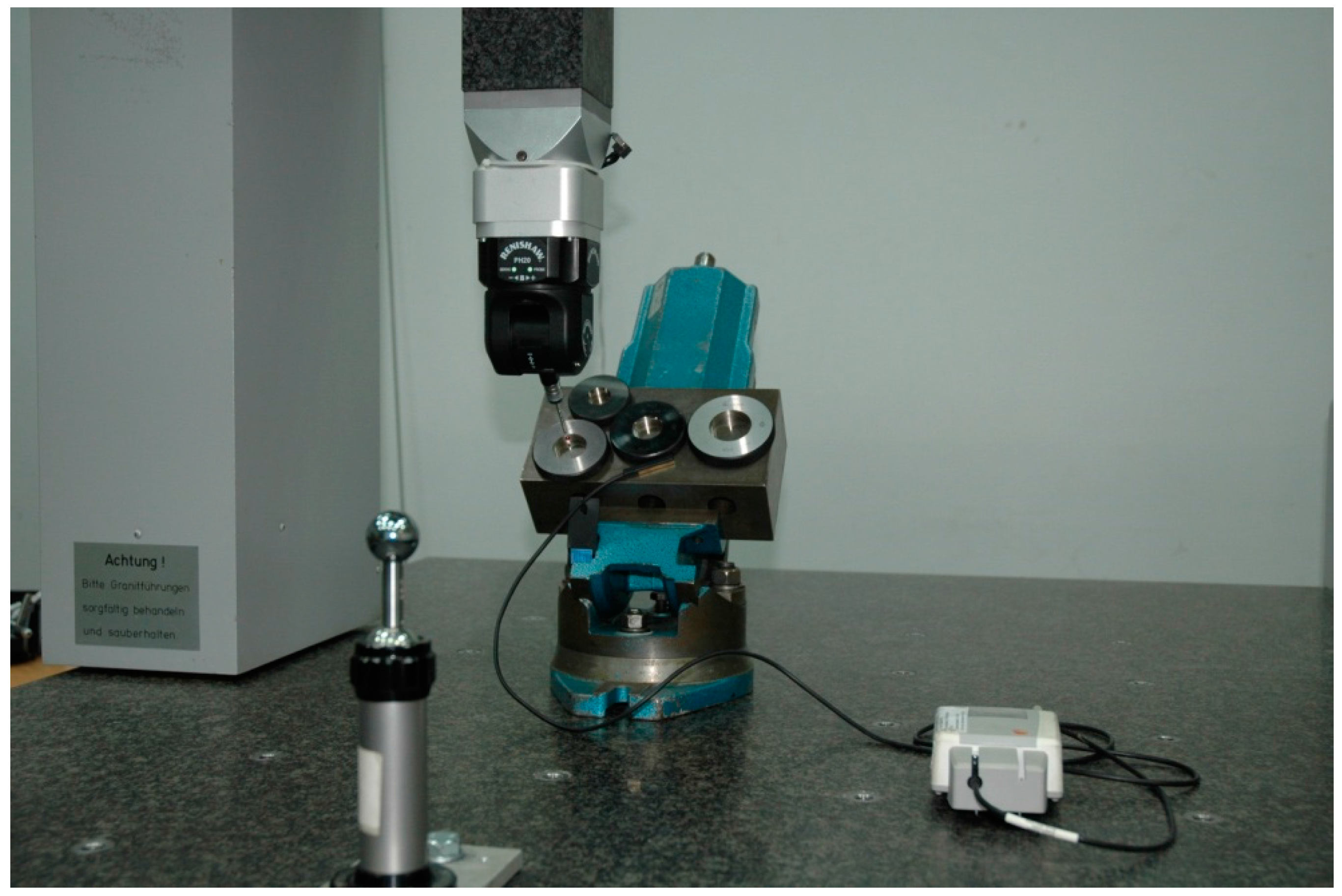
The experiences with five-axis measurements show that the overall measurement result depend on number of factors. The impact of each of them on measurement accuracy should be estimated to decide whether it should be taken into account during virtual machine preparation or it can be neglected. Several possible factors that have been examined in LCM are discussed below. All presented studies were performed using Zeiss WMM 850 s machine (Carl Zeiss, Oberkochen Germany) equipped with PH20 probe head. The machine is a bridge CMM with measuring volume of 1000 × 1200 × 500 mm. The maximum permissible errors of the machine can be described according to [
13] by Formula (1)
where L is measured length given in mm.
The room in which this CMM is located was adapted for simulating the conditions found in industry. The temperature in it may be changed from 17 to 23 °C. The experiment setup is presented on the
Figure 1.
2.3.1. The Length of Probe Stylus
The influence of stylus length for classic CMM measurements is a known subject. However, the impact of stylus length can be different in case of five-axis measuring systems because of changes it introduces to the probing process. The standard ring was measured to assess how different stylus length affects the measurements. First, it was mounted in the machine in such a manner that the ring’s axis was parallel to the machine
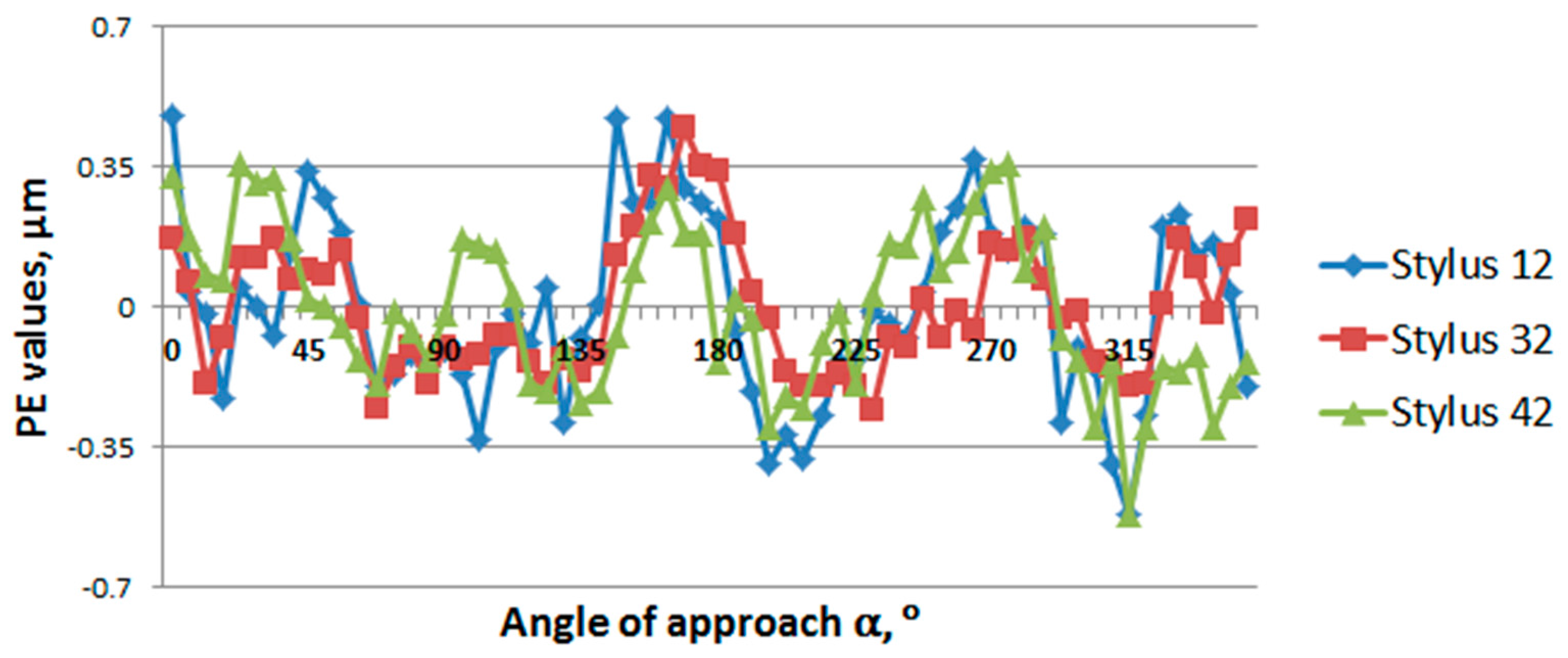
z axis. Three different stylus lengths were utilized, each time the same tip ball was used and the change in length was obtained by adding appropriate extensions. Measurements showed that change in stylus length highly influenced the diameter measurements. Deviation from nominal diameter value, was four-times bigger for longest 42 mm stylus length comparing to 12 mm stylus and reached almost 2 μm. The influence is not so obvious in case of form measurements where difference between shortest and longest of used styli not exceeded 1 μm. What is even more important is that the results show that probe errors (in the sense as set forth in [
1]) vary slightly with changes in the stylus length.
Figure 2 shows the PE values for different styli lengths depending on the changing angle of probe approach α.
However, such a standard ring arrangement is favorable for the system’s accuracy because the head will first rotate around vertical axis, then only the rotations around the horizontal axis are used during measurement which means that all points can be measured practically using the same contact point on the probe tip. The experiment was then repeated for different arrangements of the ring in which each point is measured using different probe deflection and head angles. In this case, less obvious results were obtained. The stylus length influence on measurements of diameter and form error was at similar level, with differences between deviations observed for the shortest and longest styli not exceeding 1 μm. The observed probe errors showed bigger instability, and their values slightly increased with extending stylus length. This experiment showed that stylus length is a factor that has to be included in the model of a five-axis system, the question is if it can be modeled just by changing stylus length in a kinematic model of probe head or additional efforts, as Probe Error Function (PEF) (defined in [
1]) determination for different stylus lengths would be necessary to model that factor influence correctly.
2.3.2. Probe Head Hysteresis
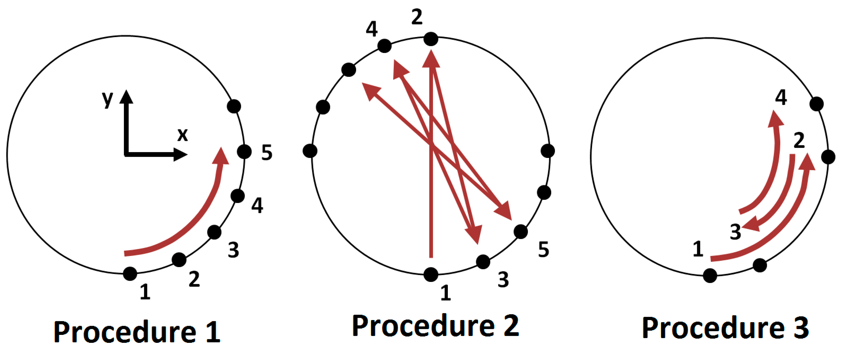
Hysteresis is a term used to describe the fact that system response to certain input depends on the order of proceeding inputs. It can be observed for various measuring systems also for the number of probe heads used in coordinate metrology. Probe head hysteresis can be assessed, for example, by measuring specially mounted gauge blocks. Three standards are pushed together, the central one extends in front of the two gauges on the sides. The two equal distances can be measured, first between the planes of the central standard block and second between the planes of the side gauges that adhere to the planes of the central block. The absolute difference between measured lengths is treated as hysteresis error. The gauge block of 14 mm nominal length was used, with two additional flatness standards on the sides. The experiment results show that mean hysteresis error in the case of measurements performed using only rotational movements of the head equals to 0.5 μm. In turn, the same experiment repeated for typical three-axis measurements gives result that is five times bigger. Hysteresis can be also estimated by measurements of standard ring. Three procedures were included in appropriate research and they are shown on
Figure 3.
The first procedure was generated by metrological software and it was treated as a reference. The other two were designed to include the influence of two rotations of the head, however each time the same points were measured and what changed was, in fact, the measuring strategy. Then the hysteresis was calculated as absolute difference between PE obtained for corresponding points of reference and tested procedure. The results show that the biggest mean hysteresis error was obtained for the second procedure and it equaled about 1.5 μm. The influence of hysteresis on the overall result is hard to estimate. It occurs only in certain conditions so it cannot be included in each measurement. Generally, hysteresis should not be a case for unidirectional measurements—for example, flatness measurements—or basically when the probing path is guided without changing the head rotation direction. However, in cases of manual programming of the machine, it becomes a bigger problem because different criteria like operator convenience or the tendency to minimize program duration are taken into account much more frequently than avoiding the effect of hysteresis. It is hard then to include the influence of the hysteresis directly in virtual machine software. In the case when hysteresis should be included in overall uncertainty, its influence may be added to this value using the propagation of the uncertainty rule, where the result of the simulation performed using virtual CMM methodology is one of the uncertainty contributors and hysteresis along with other similar influences (if applicable) are other contributors.
However, the hysteresis changes depending on the measurement task. Research conducted in LCM shows that hysteresis variability in the case of probe head used in five-axis measuring systems is small (standard deviations do not exceed 0.3 μm) so it should not disturb the simulation process performed by the virtual machine.
2.3.3. Measured Workpiece’s Form Errors Influence
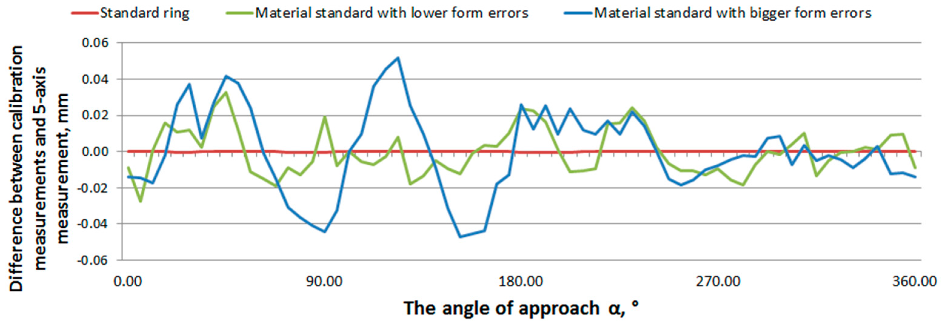
An interesting problem that occurs during measurement with five-axis measuring system is the accuracy loss in case of measurement of objects characterized by large form errors. The authors proposed an experiment to assess the impact of this factor. Two standards in the form of cylinders were designed with preliminarily determined form errors described using the relevant cosine functions. The first standard was characterized by lower form error (roundness) value equal to 0.5 mm, the form deviation of the second one was 1.6 mm. The diameter of both of them equaled 39 mm. They were manufactured using additive manufacturing technology. In the next step, both standards and a standard ring of similar diameter were calibrated according to calibrated workpiece method on the highly accurate CMM machine. After the calibration process, standards and the reference ring were measured on a five-axis measuring system, using only rotational movements of head. The measurements were performed using the same strategy that was utilized during calibration.
Figure 4 presents the mean difference between radial error for certain α angle obtained during calibration and measurements on the five-axis system. The biggest differences were obtained for manufactured standards burdened with the largest form errors. As one possible cause of such accuracy loss, some simplifications of algorithms utilized in the metrological software may be taken. The predefined form errors cause the tip of stylus to hit the surface of the measured object in different points that are expected for generated measurement code. That means that the rotation angle in one of the probe head’s axes reaches higher or lower values than in case of measurement of points generated for nominal features. Thus, the radial correction of the tip ball may be done in a different direction than it should be, which can introduce additional errors.
2.3.4. Other Error Sources
Other possible error sources include influence of probe head calibration and algorithms used for controlling a probe head measuring path. Calibration in the case of articulating probe heads with continuous orientation differs from that used for typical CMMs. It is divided into two parts: head calibration and probe calibration. Both are based on measurements of calibration sphere, but additionally the optimal touch speed and probe head maximal acceleration are determined. Furthermore, the calibration sphere is measured with various orientations of probe head which can determine the map of probe head errors. Studies conducted at LCM shows that calibration has certain impact on the measurements results, especially on measurements of length, to a minor extent it also affects form error measurement.
Additionally, the functioning of five-axis systems can be affected by the algorithms responsible for measuring path controlling. For example, the dedicated software offers number of possibilities for cylindrical feature controlling which include measurements done from a fixed position of head or measurement path along the centroid. Depending on the chosen option, the difference between coordinates obtained along the cylinder axis can vary even in tenth of mm which, of course, affects the measurement result.
It is extremely important to properly consider the impact of individual factors on the uncertainty of measurement which is a result of the virtual machine operation. Influence of factors such as length of stylus can be included into kinematic or probe head errors models. The situation is more complicated in case of factors like probe hysteresis or influence of probe calibration. Impact of the last of mentioned factors will not be visible with simulation because each time the same radial correction will be applied for certain measured points. However, if the value of actual tip ball radius would be burdened with error it would be transferred into measurement results. Therefore, it may be necessary to estimate the uncertainty associated with each of the factors and then include all of them as well as uncertainty obtained through the simulation in overall measurement uncertainty (e.g., using the propagation of uncertainty rule).
The next source that should be taken into account is the influence of ambient conditions, especially temperature variations. The aforementioned geometrical model of the kinematic structure assumes that the mechanism is functioning at the reference conditions, i.e., at a temperature of 20 °C. Deviations from this temperature causes changes in the values of geometric parameters, especially those expressing the length. Implementation of a model which does not accommodate changes of parameter values with the temperature variation would lead to discrepancies between the actual position of the stylus tip center, and the position calculated using the forward kinematics.
The research presented in [
14,
15] shows that the thermal influences have a strong impact on the geometric accuracy of different kinematic structures. The influence of the temperature is not only connected with the linear expansion of materials. The temperature gradients of mechanism parts and the gradients of ambient temperature should also be considered as influences disturbing the accuracy of manipulators. Some of the errors connected with the temperature may be minimized by using resistant materials or sophisticated construction of the manipulators, however the thermal effects cannot be fully compensated. This is why the temperature influences should be incorporated in the Denavit–Hartenberg parametric model and then verified experimentally.
3. Summary
As it was shown above, the virtual model preparation for five-axis measuring system is a challenging task and many issues have to be solved before a fully functional model can be obtained. However, the authors believe that a system which was developed for acceleration of measurement process need a modern and fast method for uncertainty estimation. Virtual models can determine uncertainty almost on-line which not only reduces costs for producers but also may contribute to spreading the good metrological practice of giving the measurement results together with task-specific uncertainty. Application of a virtual machine for determination of measurement strategy that ensures the best accuracy may limit incorrect decisions in quality control.
In this article, the authors tried to present a direction for further research, however the discussion focused mostly on five-axis systems that utilize touch-trigger probes. Models for such systems would be a basis for an even more challenging problem, the virtual machine for five-axis scanning measurements. There is no satisfactory solution for this issue even in the case of typical three-axis CMMs. Additionally, measuring probe heads that works with five-axis systems differ in construction from the well-known measuring heads. They use a laser beam that travels through a hollow stylus and then is reflected by the mirror attached to the spherical tip of the probe. It introduces new challenges related to the functioning of probe heads of this type and the idea of a virtual model of five-axis measuring system presented in this paper would have to be changed because of it. It should be possible to use the same methodology regarding the modeling of a kinematic system of the five-axis CMM and modeling of other sources not connected directly to probe head functioning (e.g., influence of software or measured workpiece), but the model of probe head kinematics and errors dedicated to measuring probe heads would have to be developed separately.
Further research on this subject conducted at LCM will be consequently published. The authors hope that the studies on accuracy of five-axis coordinate systems will also be undertaken by other research centers in the world. It would help in faster development of methods for identification of errors and assessing the uncertainty of measurements performed using them. It would finally help in faster development of five-axis measuring systems themselves.


