1. Introduction
Narrow gap welding (NGW) refers to butt welding applied to a narrow groove between two thick plates, where the gap between the two plates is of Type I, or a similar type. Butt welding is considered NGW when the groove angle is less than 20°. Through NGW, high productivity and quality can be achieved and thermal deformation and residual stress can be minimized; it can also be used in any welding position, including vertical upward and downward positions. Owing to such advantages, NGW is frequently applied to nuclear power plants where numerous welding works on piping and equipment are required. In particular, since stress corrosion cracking (SCC) accidents are frequently caused by the residual stress from welding in many nuclear power plants, maintaining the soundness of device welding, including the welding of pipes in nuclear power plants, is becoming one of the most critical safety issues to ensure the safe operation of nuclear power plants [
1,
2,
3,
4]. Generally, the welding method for the piping of a nuclear power plant requires a large bevel angle and multiple welding passes. Therefore, the size of the welding part proportionally increases and, consequently, the residual stress and the possibility of welding defects also increase. To resolve these issues, studies on NGW are currently focused on the welding process for piping and machinery in nuclear power plants. In addition, studies on NGW are also focused on developing new equipment that enables welding in narrow spaces and on applications of new welding processes [
5,
6,
7,
8,
9]. Likewise, NGW has the advantage of ensuring high-quality welds with low welding deformation and residual stress while, at the same time, enabling higher productivity than the existing thick plate welding method through an efficient, narrow welding joint.
This study focused on NGW for MIL-STD-12560-grade armor steel, which is used for caterpillar-type and wheeled armored combat vehicles. Combat vehicles, such as tanks, use materials with excellent impact toughness (armor steel, MIL-STD-12560) in order to ensure the safety and survival of the crew. Depending on the position of the crew and the structural importance, 30–150 mm thick armor steel is applied. In the welding joint design for armor steel, the size and shape of the bevel angle are determined within the bevel angle range (45~55°) of the joint, as determined in accordance with MIL-HDBK-21. To ensure the strength of the welding part, using a wide bevel angle is usually preferred, based on experimental data. In particular, the welding design for combat vehicle structures is applied rather conservatively, wherein the bevel angle is excessively wide, or the shape of the welding joint is almost precisely determined to be as verified, since protecting the structure is directly related to the life and death of the crew. In this case, as the thickness of the material increases, issues arise, such as welding deformation and residual stress due to the increased number of welding passes, which are required by the welding bevel angle. When residual stress occurs in the welding part, cold cracking occurs due to the high equivalent carbon content and susceptibility of cold cracking. Moreover, the impact toughness of the welding part decreases due to the excessive welding heat input, and the productivity of the process decreases due to the high number of welding passes. To resolve this, the present study is focused on the characteristics of NGW parts in armor steel in order to apply NGW to the welding part of armor steel used for combat vehicles. Therefore, the mechanical properties and low-temperature impact toughness of the existing welding part and the NGW part were comparatively evaluated; furthermore, the residual stress was experimentally and analytically investigated. Finally, a ballistic test was conducted on a NGW part to confirm the protection performance, which is required for the welding part of armored vehicle.
2. Experimental Procedures and Results
2.1. Welding Joint Design
The material used for this study is a MIL-STD-12560-grade armor steel, which has excellent impact toughness. The chemical and mechanical properties of the armor steel are shown in
Table 1 and
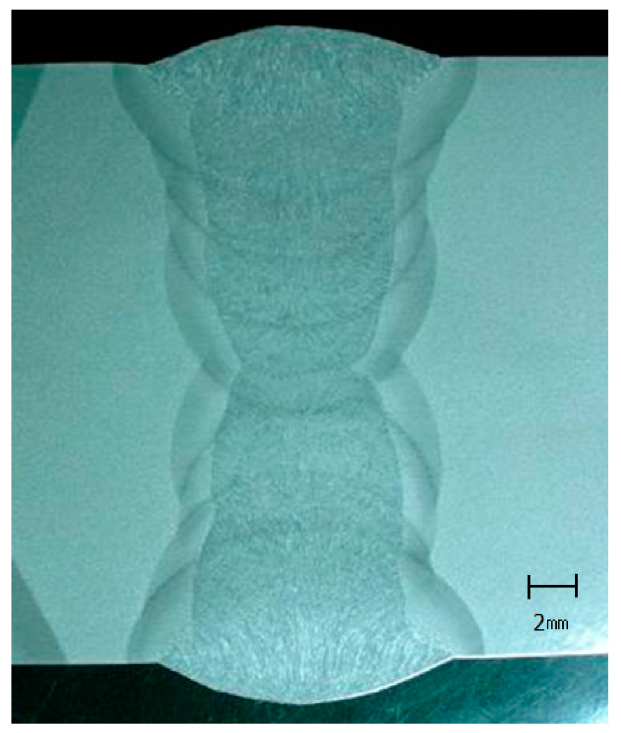
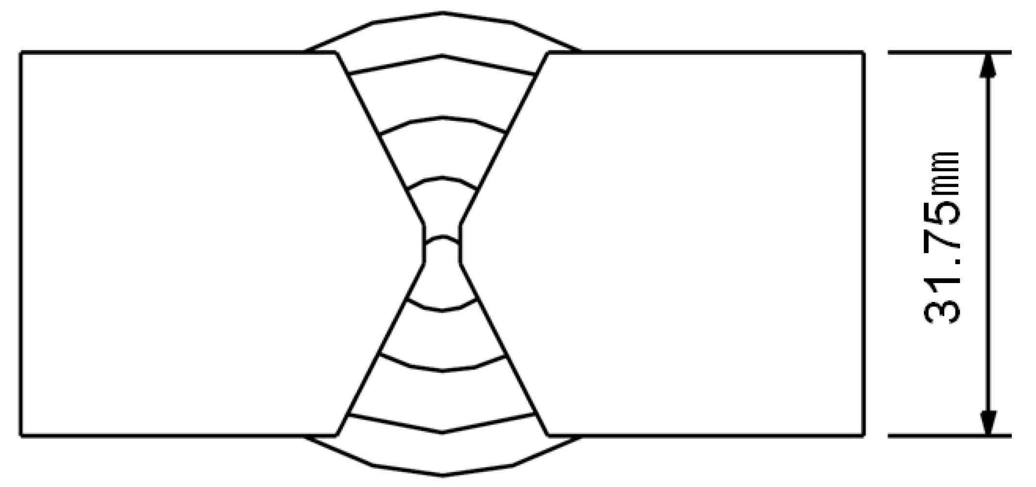
Table 2. AWS A5.10, MIL-100s grade filler metal was used. As is typical of NGW, a lack of fusion frequently occurs on the lateral side on the inside of the narrow gap, which stems from the low thermal inflow and small molten pool. This is a critical defect that negatively influences the bond strength. Moreover, due to the long, narrow gap, welding defects also occur when the welding torch cannot reach the first layer welding or when it is insufficiently protected by the protective gas. These all aggravate the quality and welding strength of the weld. To obtain a reliable welding part when applying the GMAW (gas metal arc welding) process while considering these factors, the shape of the welding joint shown in
Figure 1 was designed and applied. GMAW is a welding process in which an electric arc forms between a consumable wire electrode (filler metal) and the workpiece metals (base metals). Through the macro test, the soundness of the welding part was confirmed, as shown in
Figure 2. To ensure the convenience of the industrial application, only the GMAW process was applied without developing an additional device or process. The macro test is performed on the cross-section, longitudinal section, or any direction as an independent test to evaluate the subsurface conditions or as a subsequent step of another test to reveal the effects on the subsurface. The order of the welding deposition of the NGW and X-groove are shown in
Figure 1 and
Figure 3, and the welding conditions are shown in
Table 3.
2.2. Comparision of Mechanical Properties
The mechanical properties of the welding part applied with NGW were compared with the characteristics of X-groove weldment. The mechanical properties were evaluated by tensile testing to confirm the welding joint efficiency by a Charpy impact test at low temperatures, and by comparatively evaluating the hardness distribution of the welding parts.
2.2.1. Tensile Test
Tensile tests were conducted to compare the tensile properties of the X-groove and NGW parts. The tensile specimen was prepared in accordance with ASTM E8M-05. The tensile test was conducted under a load of 100 kN with a universal testing machine (Instron 8501, Instron, Norwood, MA, USA). The specimens were loaded at a rate of 1.5 kN/min, as per the ASTM standard.
The results shown in
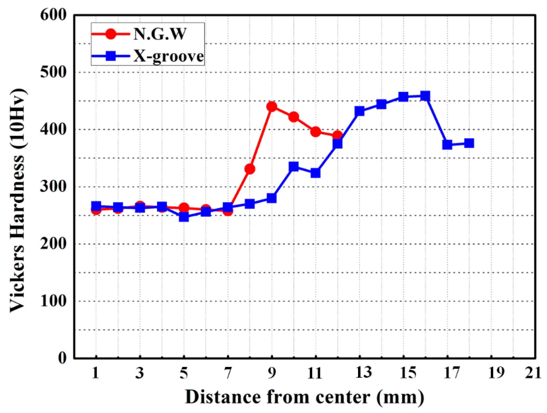
Table 4 are the average value of five specimens. As a result, the NGW part demonstrated a better yield strength, tensile strength, and elongation percentage than the X-groove part. This is because the total welding heat input energy is lower in NGW than in X-groove, the conventional welding joint, which specifically causes the improved tensile strength and elongation percentage. Additionally, lower welding heat input energy of NGW can be explained by comparison of hardness distribution as shown in
Figure 4. Narrow and low hardness values of HAZ (Heat Affected Zone), which provides ductile characteristics, helps to improve tensile strength and elongation in NGW.
2.2.2. Low-Temperature Impact Test
For the low-temperature impact test, the specimens were prepared in accordance with the ASTM E 23, using a Charpy V-notch, and the test was conducted at −40 °C. Notches were located on the fusion line, where the local brittle zone (LBZ) occurs, at the starting point of failure in the welding part, and at 1 mm away from the fusion line, to confirm the low-temperature toughness of the welding part. In the case of the low-temperature impact test, five specimens were tested, respectively, and their minimum and maximum values were excluded. The test results were averaged and are shown in
Table 5. As a result, the NGW part showed better low-temperature impact toughness than the X-groove. Similar to the tensile test results, this is due to the low welding heat energy input, and NGW is found to be more resistant to the external impacts.
2.3. Hardness Distribution
To confirm the hardness distribution of each welding part, macro Vickers hardness tests were conducted. The hardness was measured using the macro Vickers hardness test as per ASTM E92-82 (2003), with a load of 5 kg and 10 s of loading time. As shown in
Figure 5, the hardness was measured for the horizontal direction of the welding part. The hardness of the lateral direction was measured by measuring the welding part and heat-affected zone at 2 mm above the welding metal part. The results are as shown in
Figure 4. The distributions were all similar regardless of the shape of the welding joint, which affects the hardness distribution of the welding part and the heat-affected zone.
3. Measurement and Prediction of Residual Stress Distribution
The welding residual stress, also known as the thermal stress, refers to a residual stress triggered by the heterogeneous temperature distribution caused by the welding heat input, which is locally applied during the welding. The welding residual stress is a major cause of reduced fatigue lifetime of welded structures and stress corrosion cracking. Therefore, in the case of structural steel alloys, the residual stress is removed using a heat treatment after welding. However, this treatment is not applied for high-strength steel, such as steel for armor, which possesses high hardness. Therefore, the residual stress in the welding part should be predicted by a finite element method (FEM) and treated with such means as the temper bead method in order to prevent corrosion stress cracking caused by the residual stress distribution and to minimize the influence of the fatigue lifetime. In addition, in this study, the X-groove and NGW were compared using finite element analysis and X-ray diffraction (XRD) in order to confirm the influence of the welding residual stress distribution by the application of the NGW method.
3.1. Measuring Residual Stress Using XRD
XRD was used to measure the residual stress distribution of the welding part. The residual stress was measured with a portable XRD device (TEC 4000, Materials Testing, Knoxvile, TN, USA), and the measurement positions are shown in
Figure 4.
3.2. FEM Prediction of Welding Process
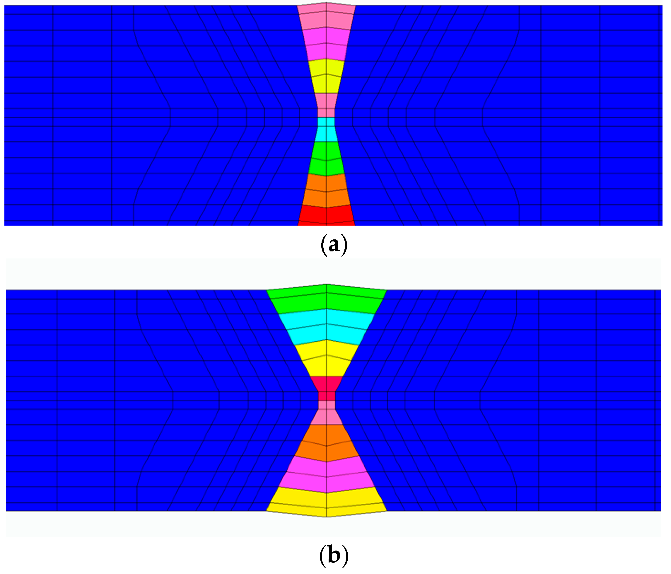
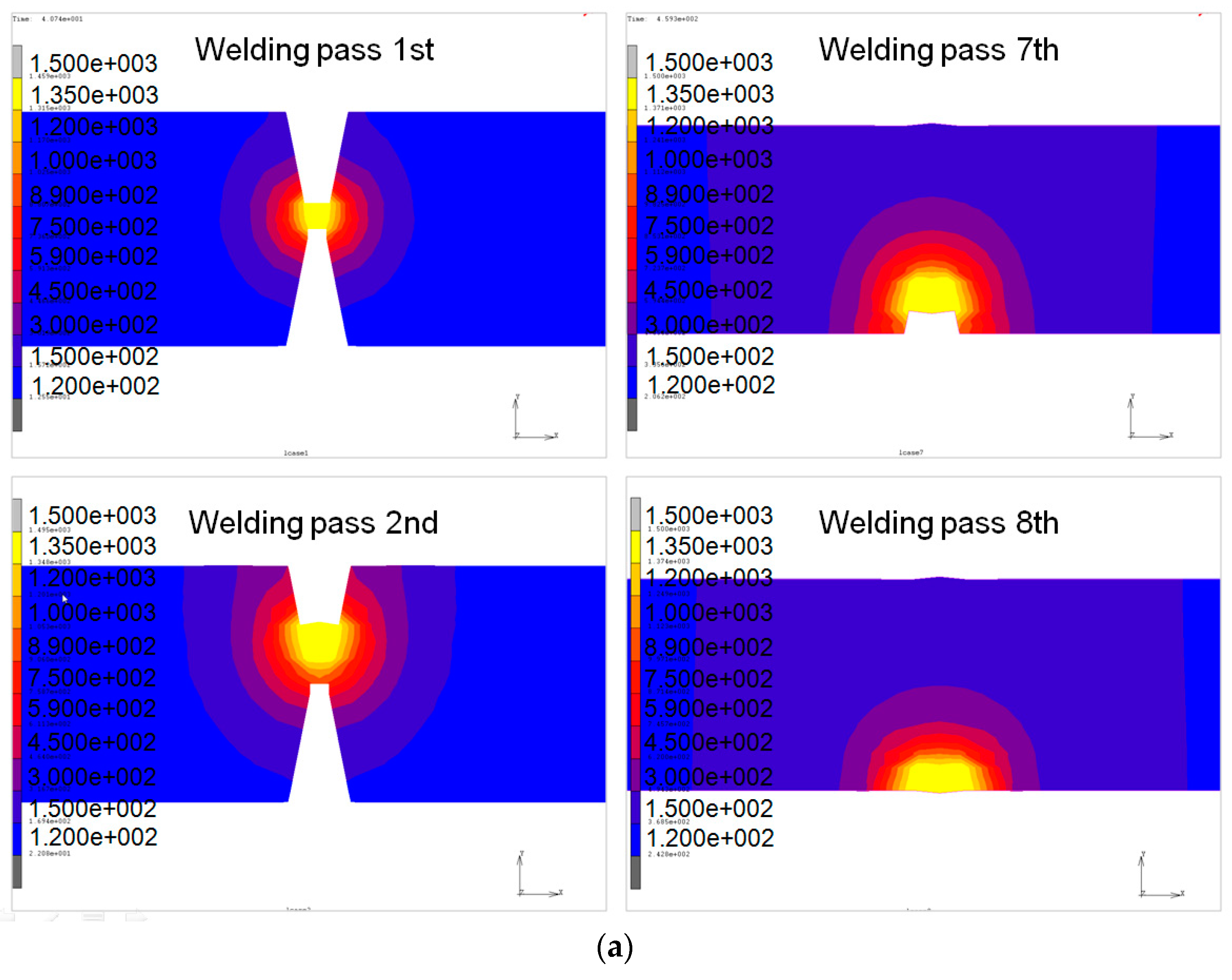
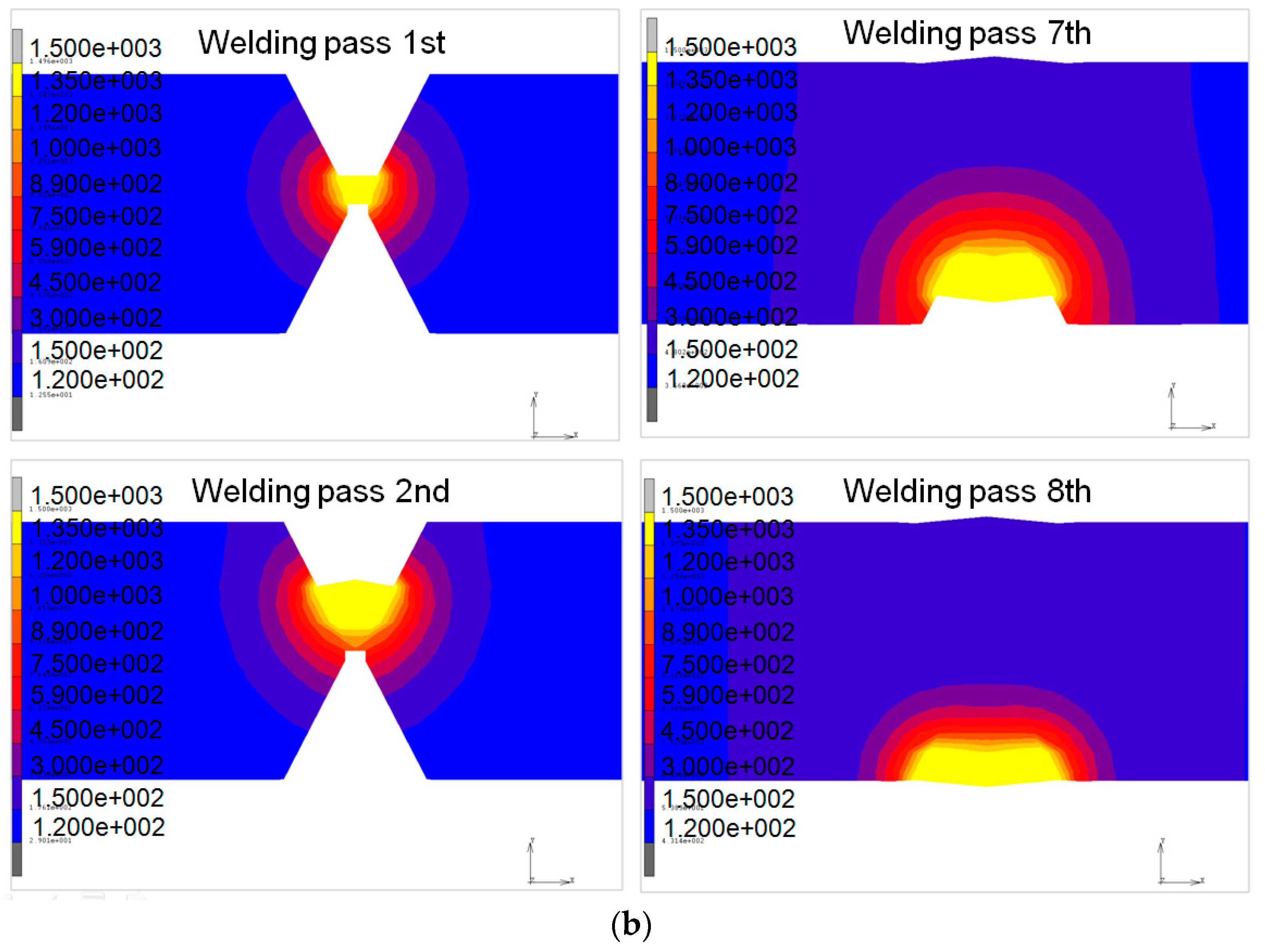
In this study, a coupled thermo-mechanical analysis is used to calculate the welding residual stress by the multi-pass welding process. The shape of the groove and the weld passes of each model are shown in
Figure 6a,b. MSC Marc software is used to conduct the thermo-mechanical finite element analyses.
Thermal Analysis
Analyses of the welding heat transfer for a given welding condition are performed in the 3D finite element analysis (FEA) models. During welding, the governing equation for transient non-linear heat transfer is:
The thermal effects due to solidification of the weld pool are modeled by considering the latent heat for fusion. The value of the latent heat is 270 J/g [
10]. The liquidus temperature,
TL, and the solidus temperature,
TS, are assumed to be 1500 °C and 1450 °C, respectively. The liquidus temperature and solidus temperatures were typed into the solidus and liquidus temperature module of MSC Marc software.
Heat losses due to convection and radiation are also taken into account in the finite element models. All surfaces of the model are assumed to lose heat by convection to the surrounding air. Heat loss due to convection is accounted for by using Newton’s law [
11]:
Here, hc is the heat transfer coefficient, TS is the surface temperature of the workpieces, and T0 is the ambient temperature. For a surface element of a solid body contacted by flowing gas or liquid, the heat flow density qr is, according to Newton’s law, proportional to the difference between surface temperature, TS, and gas or liquid temperature, T0, through the coefficient of convective heat transfer hc.
In this study, a temperature-dependent film coefficient [
12] is used and the ambient temperature is assumed to be 25 °C.
The heat loss due to radiation is modeled using the Stefan-Boltzmann law [
13]:
Here,
ε is the emissivity and
σ is the Stefan-Boltzmann constant. In this study, the emissivity is assumed to be 0.2 [
14].
In welding technology, heat dissipation of the cooling of a relatively small body (body temperature,
TS) in relatively extensive surroundings (body temperature,
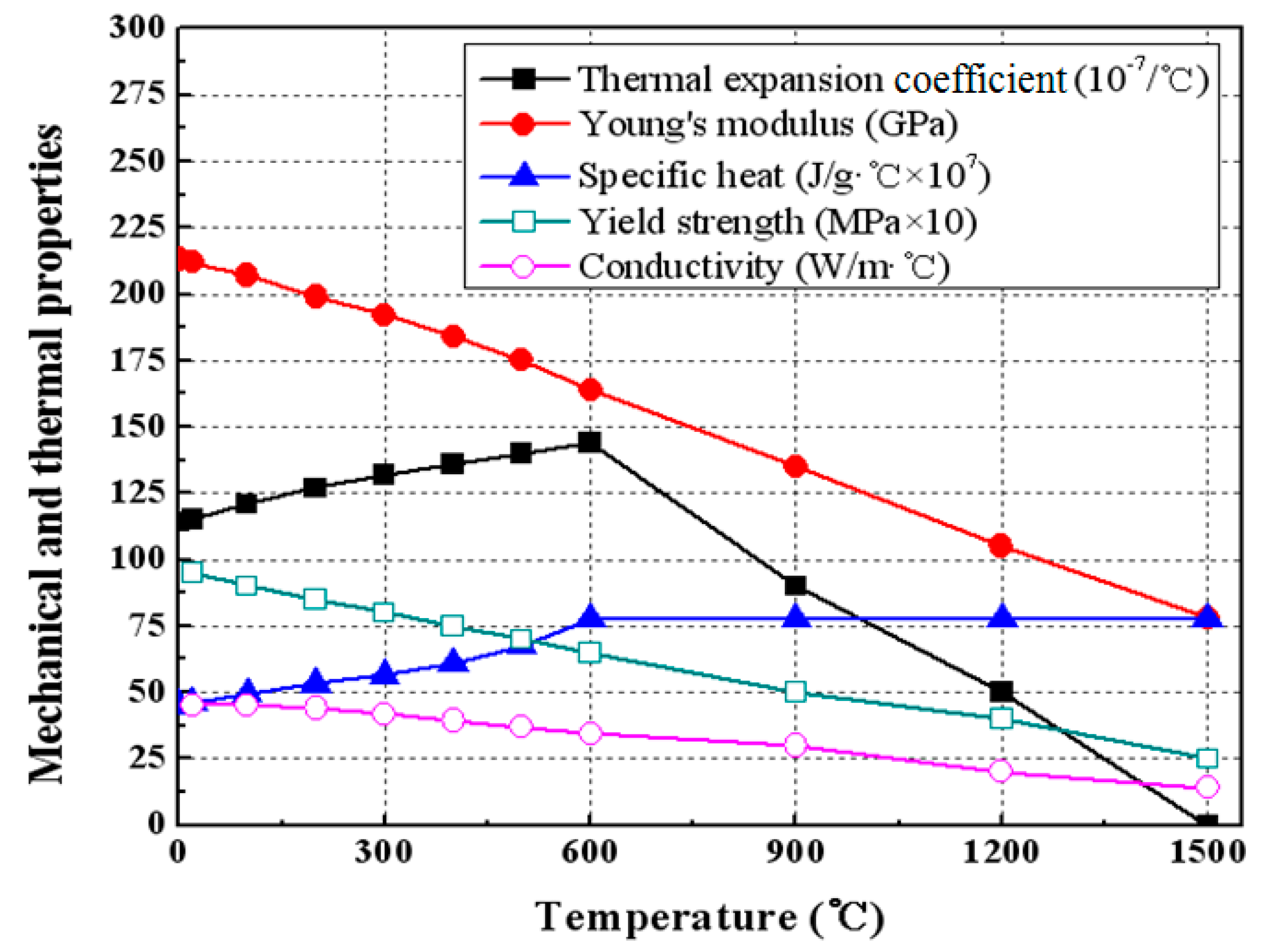
T0) occurs by means of radiation in accordance with Equation (3). Thermal conductivity and specific heat are used as the temperature-dependent thermal properties as shown in
Figure 7. The element activation and deactivation methods are used to model the deposition of weld metal during multi-pass welding. The elements of the weld deposition are activated and then heated to model the moving heat source.
3.3. Mechanical Analysis
Temperature-dependent thermal properties, such as the modulus of elasticity, yield strength, and thermal expansion coefficient, are used for mechanical analyses. Given the phase transformation of steel and its insignificant effect on the welding residual stress and deformation, the total strain can be decomposed into three components, as follows [
15]:
Here,
εe,
εp, and
εth are the elastic, plastic, and thermal strains, respectively. The elastic strain is modeled using Hooke’s law with a temperature-dependent elastic modulus. The Von Mises yield surface and temperature-dependent material properties are employed to model the plastic strain.
Figure 8 shows the temperature-dependent properties [
14]. The effect of work hardening is not considered in this study.
3.4. Heat Input Model
In this study, the heat from the moving welding arc is applied as a volumetric heat source with a double-ellipsoidal distribution, as proposed by Goldak et al. [
16]. This is expressed by the following equations.
For the front heat source:
For the rear heat source:
Here,
x′,
y′, and
z′ are the local coordinates of the double-ellipsoid model, and
ff and
fr are parameters that give the fractions of heat deposited in the front and rear parts, respectively [
16]. The temperature gradients in the front and rear are expressed by Equation (7):
Note that ff + fr = 2.0. This is done because the temperature gradient in the front leading part is steeper than that in the trailing edge. Therefore, two ellipsoidal sources are combined: one for the front half and the other for the rear half.
The parameters
a,
b,
c1, and
c2 are related to the characteristics of the welding heat source [
16,
17]. The values of these parameters used in the present study are summarized in
Table 6.
Qw is the power of the welding heat source, which can be calculated according to the welding current, the arc voltage, and the arc efficiency (8). The arc efficiency,
η, is assumed to be 0.7. The heat input energy of each weld pass is determined using the following equation:
The ramp heat input function in
Figure 9 is adopted to increase the convergence rate and reduce the time at the start of the welding analysis. A 20% ramp ratio is used in this work [
18].
3.5. Measurement and Prediction of Residual Stress
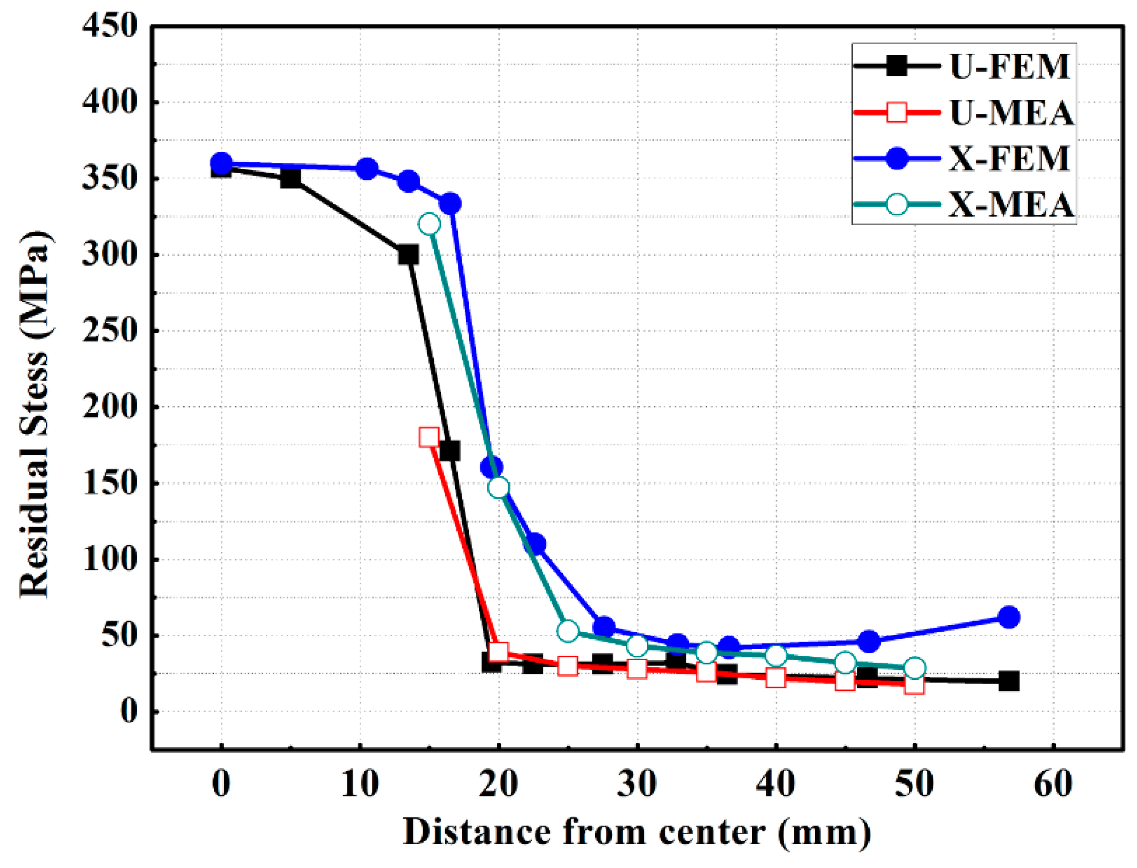
The FEM analysis results of heat distribution were described in
Figure 9 and the FEM and XRD results of residual stress were compared, as shown in
Figure 10. In general, the NGW part showed lower tensile residual stress than the X-groove. Due to the shape of the narrow beveling part, the interval where the tensile stress exists is also narrow. In the case of multi-layer welding, unlike the general single-layer welding, the tensile residual stress is offset by the subsequently applied welding bead. The tensile residual stress is created by the previously accumulated welding bead. This phenomenon was shown in both the NGW and X-groove parts. As a result of the residual stress distribution, the fatigue lifetime and corrosion resistance of the structure is expected to increase due to the existence of the tensile residual stress from the NGW joint, which is lower than that of the existing welding part. In particular, due to the deformation that occurs in the previous process, the need for additional steps to correct the residual stress, which can occur in the following process, are expected to diminish greatly.
4. Ballistic Test
The ballistic test on the welding specimens is a part of a qualification test that is applied only to the welding standard for combat vehicles. However, there are differences in the standard being applied and in the type and velocity of bullet, according to the thickness of the material. The firing test is a type of impact test that evaluates the influence of instantaneous impact on the welding part using a dummy projectile that bears the same impact strength as actual ammunition, assuming the combat vehicle is bombarded during a mission. In this test, the ballistic test using an H-plate was conducted, as per MIL-HDBK-1941. Details of the test conditions are summarized in
Table 7. The shape of the H-plate specimen and projectiles fired designated positions are described in
Figure 11.
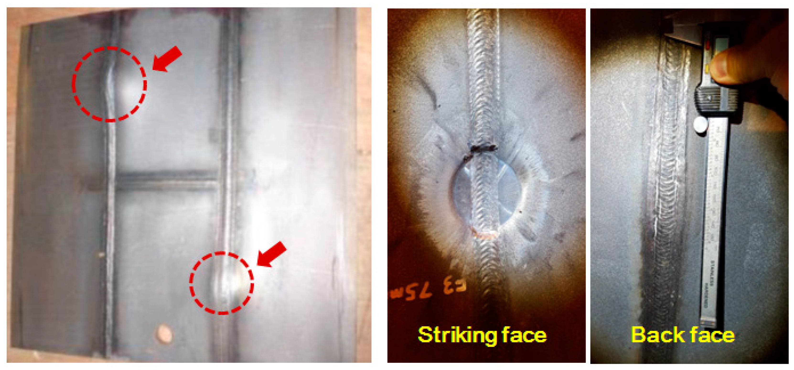
The result of the ballistic test were summarized in
Table 8. The crack length, which satisfied the impact velocity, as required by the standard, was confirmed, as shown in
Table 8 and
Figure 12. The application of NGW was found to satisfy the bombardment-resistant performance, as required by the welding standard.
5. Discussions
There are two principal methods to enhance the productivity of welding processes. The first is automated welding using machines or robots, and the other is to apply a new process or to reduce the amount of welding, as is the case in this study. Both methods reduce the time consumed for welding, but automation has limitations due to the shape of the product and initial investment costs. The main purpose of this study is to apply NGW in order to satisfy the basic mechanical and physical properties required by combat vehicles in terms of the welding of armor steel and to enhance the productivity of the welding process. The strongest feature of NGW is that it greatly reduces the amount of welding work compared to the existing method. In terms of productivity, this reduces the working hours and the overall welding heat input, which is accumulated in the welding part. These are the fundamental reasons behind all welding problems. The welding heat input refers to the calorific value applied to the welding part during the work. Quenched and tempered (QT) steel, which acquires its mechanical properties through a heat treatment and its component are refined to obtain refined steel. In this case, the embrittlement of the welding part can be triggered due to the welding heat input during the welding process, or the heat-affected zone can soften. Thus, the welding heat input is supervised under regulations. The armor steel used in this study is also regulated for the thermal input during the welding for this specific use.
When applying NGW to armor steel, the mechanical properties of the steel, including the tensile strength and impact toughness, are enhanced compared to the existing welding method due to the low welding heat input. In addition, due to this low thermal energy input, the residual stress NGW becomes lower than that of the conventional welding joint, X-groove. Through this study, the authors were convinced that NGW could successfully replace the existing X-groove welding design. NGW enhances the productivity of welding combat vehicles and related welding procedure.
6. Conclusions
This study was conducted to investigate the characteristics of a welding part, upon the application of NGW to the MIL-STD-12560 grade armor steel, which is used for caterpillar-type or wheel-type combat vehicles, and the following conclusions were reached.
When applying NGW, the tensile strength, and low-temperature impact characteristics of the welding part improved compared with those of the existing X-groove method.
When applying NGW, the tensile residual stress of the welding part decreased compared with that of the existing X-groove welding part, as confirmed by testing and FEM.
When applying NGW to the MIL-STD-12560 grade armor steel, its protection performance, as required by the standards, is ensured.


