1. Introduction
One of the most important issues in industry is efficient and continuous provision of natural gas supply. Large amounts of natural gas are used in many industries, e.g., in metallurgy, power, chemical and petrochemical plants [
1]. Natural gas is transported to these factories through transmission and distribution pipelines at different pressure ranges. Transmission pipelines can be classified by the gas overpressure range into the following categories [
2]:
Very high pressure (1.6 MPa and more),
High pressure (0.5–1.6 MPa),
Medium pressure (0.01–0.5 MPa),
Low pressure (lower than 0.01 MPa).
The high gas pressure must be reduced before entering devices and machines (e.g., boilers, engines, metallurgical furnaces, etc.). The pressure reduction station is a commonly applied technology for reducing natural gas pressure both in gas transmission and distribution pipelines. The pressure reduction station maintains constant gas pressure at the outlet of the station, regardless of fluctuations in the flow rate and pressure at the inlet to the station [
2]. Reduction of the natural gas pressure in a pressure reduction station is carried out via isenthalpic throttling without producing any energy [
3]. The gas temperature drops while throttling (ca. in the range from 2 to 7 K/MPa) [
2]. Due to the presence of steam in the gas, the temperature drop carries the risk of hydrate formation. In order to prevent this phenomenon, throttling is carried out in such a way that the gas temperature after throttling is higher than 0 °C (e.g., by pre-heating of the gas before the throttling). The assembly of a pressure reduction station is very simple. The main pressure reduction station elements are the gas filter, the gas heater, the gas pressure regulators (throttle-valves or expanders), the measuring devices (providing measurement of the gas temperature, pressure, flow rate and calorific value), the gas odorizing devices, and the safety fittings (quick-closing valves, etc.).
Gas stations can be classified by application purpose into the following groups [
2]:
Pressure reduction stations, used for reduction and stabilization of gas pressure,
Pressure reduction and measuring stations, used for reduction and stabilization of gas pressure and measuring of gas properties,
Measuring stations, used for measuring the gas flow rate or its calorific value,
Distribution and measuring stations, used for separating the gas stream to at least two output streams and measuring its parameters.
By the expansion range, pressure reduction stations can be classified into the following groups [
2]:
First stage (high pressure reduction stations), applied in high pressure transmission pipelines, providing the reduction of the gas pressure to ca. 500 kPa,
Second stage (medium pressure reduction stations) applied in distribution pipelines, providing the reduction of the gas pressure to ca. 10 kPa.
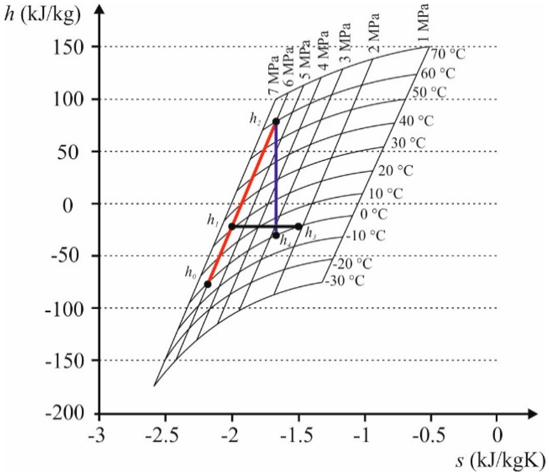
The application of a pressure reduction station for reduction of the natural gas pressure is a simple method, however, it is affected by significant energy losses (as the gas pressure energy is being dissipated during the isenthalpic expansion process).
An alternative to pressure reduction stations is a turbine or a volumetric expander. In such machines, the gas pressure reduction is achieved by polytropic expansion. The gas flow through the machine results in rotor movement. Thus, the gas pressure energy can be converted into mechanical energy useful for driving an electrical generator. However, when the gas is expanded in the expansion machine, the gas temperature drop is larger (ca. 15–20 K/MPa) [
3] compared to isenthalpic throttling. This results in an increased quantity of energy needed for pre-heating of gas before expansion. The comparison of isenthalpic throttling and polytropic expansion of natural gas is depicted in
Figure 1.
The applicability of turbines to natural gas expansion has been analyzed in a number of studies, see, e.g., Refs. [
3,
4,
5,
6,
7,
8,
9]. In [
3] it was indicated that the turbine may be an interesting alternative to the pressure reduction station. However, the turbine is mechanically complicated. In case of low power turbines, the very high rotational speeds is an important problem. This necessitates very precise turbine fitting, which in turn results in high manufacturing costs. Moreover, when the explosive natural gas is considered as the working fluid, special sealings and shaft bearings should be adopted [
10]. An alternative to a complicated and expensive turbine can be a volumetric machine. Volumetric expanders are mechanically simple, and thus cheap. Examples of such machines are: rolling piston, screw, scroll, piston, and lobe expanders. Nowadays, volumetric expanders are present in almost all industry branches. These machines are applied, e.g., in small and medium power organic Rankine cycle systems (ORCs) [
11,
12,
13,
14,
15] and as pneumatic engines in mining or automotive industry [
16]. The general advantages of volumetric expanders compared to turbines are [
15]:
Low cycle frequency,
Low specific speed,
High pressure drops in one stage,
Low rotational speed (approx. 3000 rev/min),
Ease of hermetic sealing.
The disadvantages are [
15]:
Internal friction, reducing the efficiency and reliability of the machine,
Need for lubrication and frequent replacement of wearing parts,
Large weight in relation to power and efficiency,
Internal and external leakages reducing expander efficiency.
Rolling piston expanders are especially promising for natural gas pressure reduction. Their most important advantages are: very simple design, suitability for wet gas conditions, negligible clearance volume, and ease of gas-tight sealing. The issues concerning the rolling piston expander design and its application in the industrial systems utilizing waste or renewable energies are innovative, and not fully described scientifically. The results of initial experiments on a small power ORC system adopting the rolling piston expander system, are reported in [
17]. The results of this experiments confirmed that it is possible to feed the rolling piston expander with low-boiling working fluid instead of air. However, it was presented in this paper that rolling piston expanders are still at the level of lab prototypes, or under research.
The analysis of the suitability of this type of expanders for natural gas pressure reduction has not been conducted so far, and therefore requires comprehensive study, i.e., analytical as well as experimental analysis. Encouraged by the advantages of rolling piston expanders described above, as well as by promising experimental results [
17], the authors decided to comprehensively assess the suitability of rolling piston expanders for natural gas pressure reduction.
In the consecutive sections we analyze the assembly and introduce a mathematical model of a rolling piston expander, and present the results of analytical modeling. Computational analysis of the operating parameters of the expander and its performance were carried out using a novel mathematical model, taking into account various geometrical dimensions and construction parameters. Moreover, the authors defined a novel assessment parameter, i.e., Power Recovery Factor (PRF), which can be used for assessing the efficiency of the energy regeneration in a rolling piston expander fed by natural gas. The PRF was used to assess the various construction solutions of the rolling piston expander. The results obtained from this research indicate that rolling piston expanders with specific geometrical design parameters have the potential to be used for energy regeneration in natural gas pressure reduction stations.
2. The Assembly and Mathematical Description of a Rolling Piston Expander
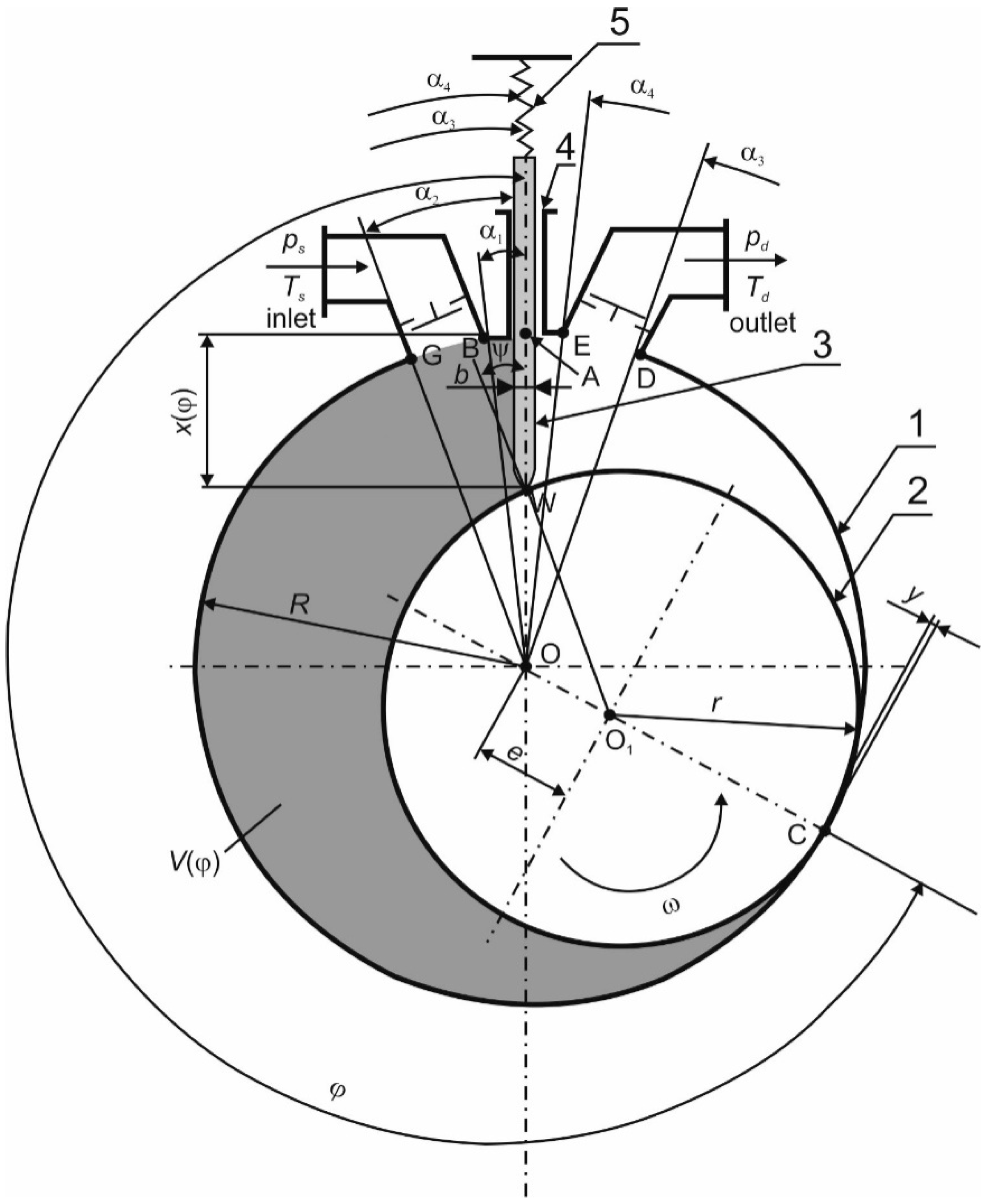
The assembly of the rolling piston expander is described as in
Figure 2. The main machine elements are: cylinder (1), rolling piston (2) and sliding vane (3). The vane (3) is placed in a slot (4) and is pressed to the piston surface with help of a spring (5). The vane remains in close contact with the piston. The piston is mounted eccentrically in the cylinder on rolling bearings. The radii of the pistons
r and cylinders
R, the lengths of the cylinders
L and the value of eccentricity
e may vary, depending on the machine power and design. It is generally assumed that these values are related to each other as follows [
18,
19,
20]:
e = (0.008–0.2)
R,
L = (1.5–3)
R. Between the surfaces of the cylinder and the piston, radial gap of width
y is formed. The width of the gap ranges from 0.1 to 0.15 mm [
19]. Small dimensions are characteristic of small power expanders, while larger dimensions are used in large power expanders. The cylinder is usually made of cast aluminum alloy, while the piston is usually made of rolled steel. The vane is made of different materials. The commonly used materials are graphite, or cured silicone doped with graphite and textolite. The inlet and outlet port edges (G, B, E and D in
Figure 2) are referred to as the machine “steering edges” [
21]. The timing of the machine operation may be performed using steering valves, or by the proper arrangement of the “steering edges”, i.e., the edges of the inlet (points G and B in
Figure 2) and the outlet port (points E and D in
Figure 2). The position of the “steering edges” is defined by the angles α
1, α
2, α
3 and α
4 (see
Figure 2 for details). α
1 and α
2 are the angles which define the inlet port edges. α
3 (also referred as the filling angle [
21]), and α
4 (also referred as the evacuation angle [
21]) are the angles which define the outlet port edges. The proper arrangement of the “steering edges” has a significant influence on the expander operation. This issue is comprehensively described in [
21].
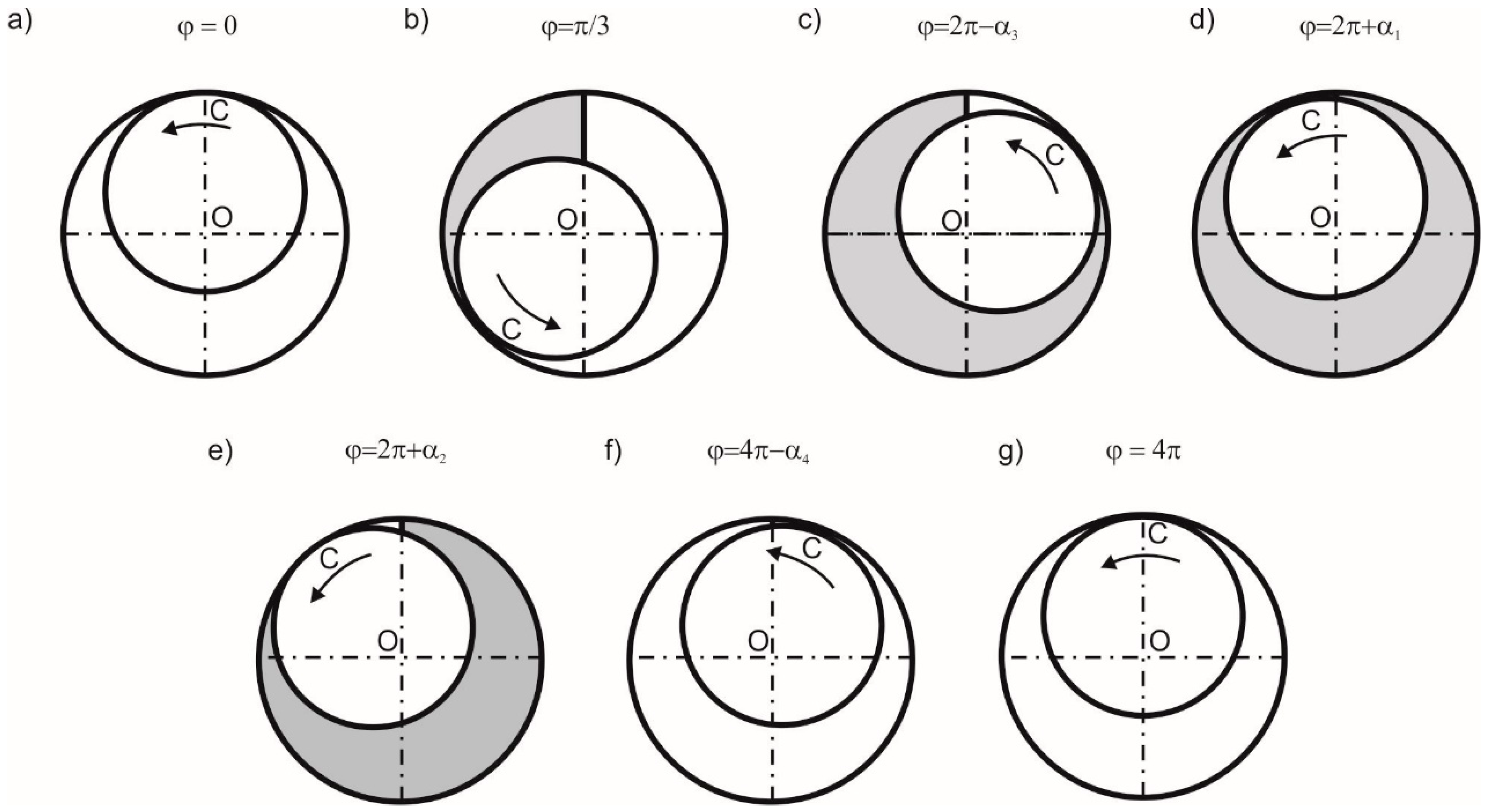
The working principle of a rolling piston expander can be described on the basis of the
Figure 2,
Figure 3 and
Figure 4. The expander working cycle begins when the rotating piston reaches the position defined by the angle ϕ = 0 (in
Figure 4 it is represented by Point 1). In this position of the piston, the volume of a working chamber is equal to
V(ϕ) = 0 and both the inlet and the outlet valve are closed. The working chamber is limited by the surfaces of the cylinder (1), piston (2) and vane (3) (see
Figure 2). In the rolling piston expander two working chambers coexist in a single moment of time and the gas is expanded concurrently in both chambers. This feature results in continuous machine operation. The working cycle continues, and when piston reaches the position defined by the α
1 angle (in
Figure 2 it is represented by Point B), the volume of the working chamber slightly increases, the inlet valve opens, and the working fluid flows into the working chamber through the radial gap (
y) formed between the surfaces of the cylinder and the piston. The rate of pressure increase depends on the width of the radial gap
y, the machine rotational speed, and the working fluid thermal properties, namely the pressure (
ps) and temperature (
Ts) at the expander inlet. When piston reaches the position defined by the α
2 angle (in
Figure 2 it is represented with Point G) the inlet port is fully opened to the working chamber. During further counter-clockwise piston movement, the filling of the working chamber continues. The filling of the working chamber ends when the inlet valve closes (typically when the piston reaches the position defined by the angle ϕ = π/3 [
20,
21]). In
Figure 4 it is represented by Point 2. At this stage a portion of the working fluid is still enclosed within the working chamber. During further counter-clockwise piston movement, the working chamber increases its volume, and the gas is expanded. The expansion ends when the piston reaches the position defined by the α
3 angle (in
Figure 2 it is represented with Point D, and in
Figure 4 with Point 3). The working cycle proceeds, and when the piston reaches the position defined by the angle ϕ = 2π + α
1, the inlet valve opens again. The second working chamber is filled with working fluid flowing through the inlet port. When the piston reaches the position defined by the angle ϕ = 2π + α
2, the outlet valve opens and the evacuation of the gas enclosed in the first working chamber starts (in
Figure 4 it is represented by Point 4). The evacuation proceeds simultaneously with the expansion of the working fluid in the second working chamber, and ends when the piston reaches the position defined by the angle ϕ = 4π − α
4 (in
Figure 4 it is represented by Point 5). The outlet valve closes at this point. During further counter-clockwise piston movement, the residual working fluid (remained in the first working chamber after the evacuation) is compressed (see process 5–1 in
Figure 4). The expansion of the working fluid in the second working chamber ends when the piston reaches the position defined by the angle ϕ = 4π (i.e., after two full revolutions). The expander working cycle is completed at this point.
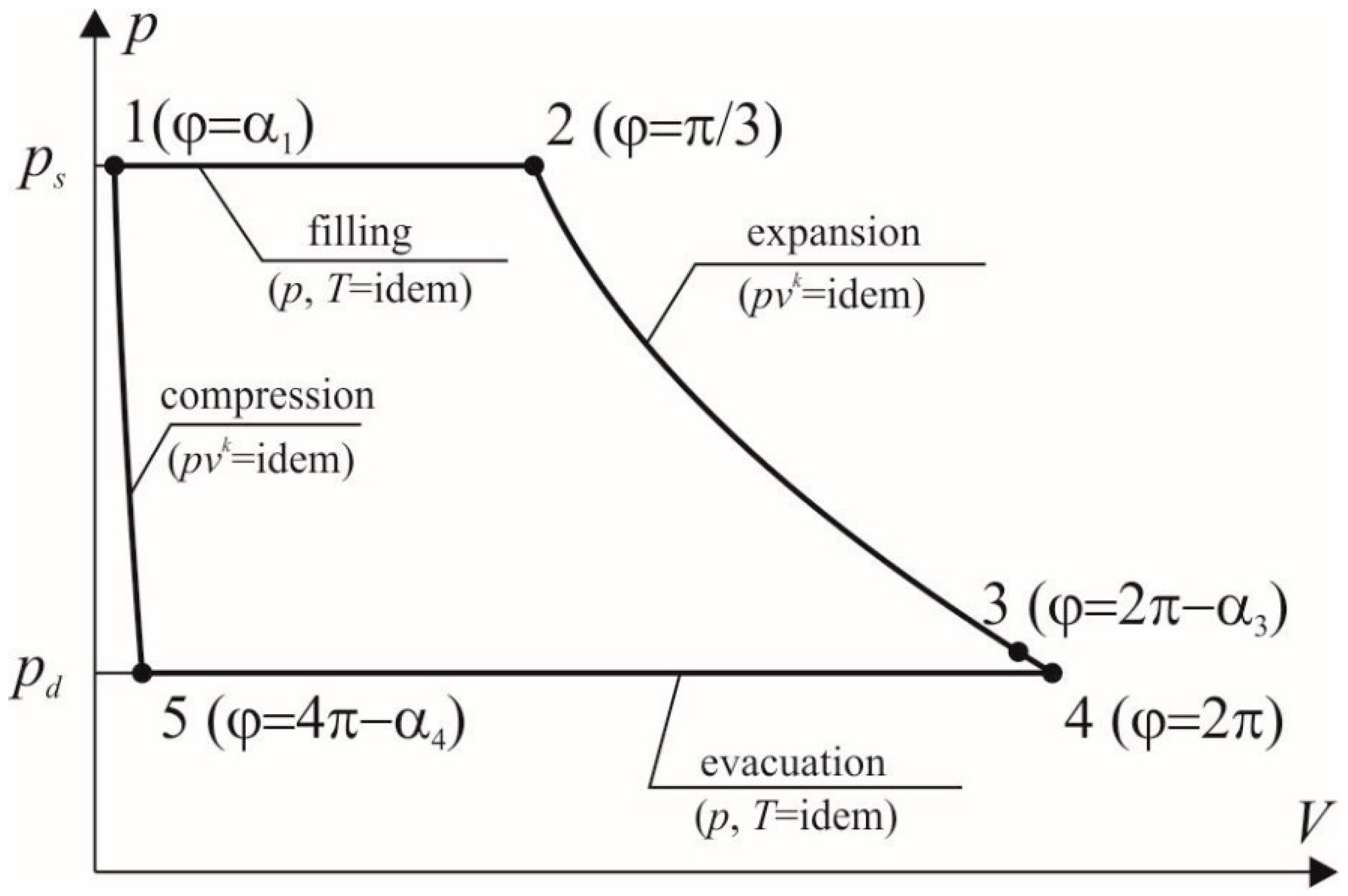
The ideal rolling piston expander working cycle (see
Figure 4) is formed by four ideal thermodynamic processes: isobaric filling (1–2), adiabatic expansion (2–3), isobaric evacuation (3–4–5) and adiabatic compression (5–1). The real working cycle is different from the ideal cycle as it is affected by energy dissipation phenomena i.e., under and overexpansion, friction, internal leakages, pressure losses, etc. These issues are comprehensively described in [
19,
20].
The mathematical description of the rolling piston expander can be described on the basis of
Figure 2. The rolling piston expander working parameters are related to its geometrical dimensions (i.e., the cylinder radius
R, the piston radius
r, the eccentricity
e, the vane thickness
b, the vane coordinate
x(ϕ), the cylinder length
L, the radial gap width
y) and the steering angles. The position of the piston is defined by the angle ϕ. In the Cartesian coordinate system, the position of the contact point (W), between the piston (2) and the vane (3) (see
Figure 2), is described by the variable angle ϕ
w and the variable piston radius-vector ρ
w. While ψ is the angle between ρ
w and the vane vertical axis. The length of ρ
w changes with the changing piston position and can be described by the equation:
As observed in
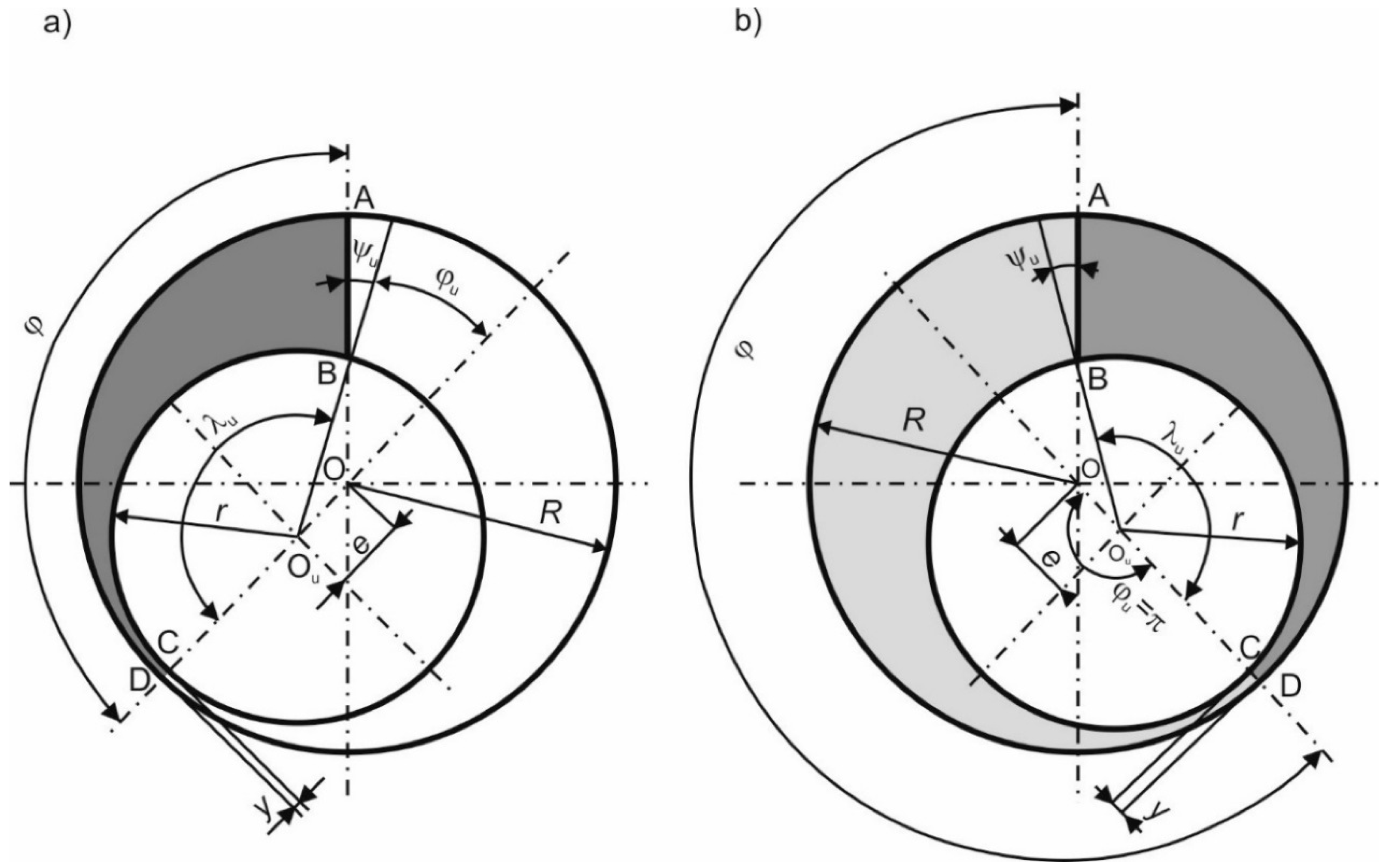
Figure 2, the vane divides the working volume into two working chambers. In the following description, it is assumed that the position of the working chamber is described by the position of the contact point (C) between the piston and the cylinder. As mentioned earlier, the expander working cycle is completed after two full revolutions of the piston (∆ϕ = 4π).
Figure 5 shows a scheme useful for the determination of a working chamber volume. The volume of the working chamber, whose position is defined by the angle ϕ (see
Figure 5), can be described by the equation:
where:
AABC(ϕ) is a cross sectional area of the working chamber. The cross sectional area can be determined using the calculation procedure valid for multi-vane expanders. This procedure is comprehensively described in [
14,
21].
The angle between Point B and Point C (see
Figure 5) can be described by the equation:
The volume of the working chamber, whose position is defined by the angle ϕ, can be described by the equation:
where
Zk(ϕ
u) is a function dependent only on construction parameters and the chamber position:
The
Zk(ϕ
u) function is comprehensively described in [
21].
The additional parameters can be described by the Equations (6)–(8):
If ϕ > π,
AABC(ϕ) (see
Figure 5a) the cross section area can be described by the equation:
The
AABD(ϕ) cross sectional area can be calculated similarly to
AABC(ϕ) if ϕ < π (see
Figure 5b). The position of the working chamber is described by the angle ϕ
u = π, the angle of vane inclination to the piston radius is ψ
u, and the angle between point B and point C is λ
u (see
Figure 5b). The additional parameters can be described by Equations (10)–(12):
The ABD cross sectional area can be described by the equation:
If 2π < ϕ < 4π, the volume of the working chamber can be described by the equation:
The theoretical power output of a rolling piston expander can be obtained with the equation:
It is also possible to calculate the theoretical power output using the equation:
where:
is the reference expander power and depends on the geometric parameters and working fluid properties. The method of the reference expander power calculation is comprehensively described in [
21]. The presented model is a novel and helpful tool that can be applied for the modeling and optimization of the geometry of a rolling piston expander, and the selection of optimal operating parameters for high efficiency. The model is based on the relationships between specific geometrical parameters (
e,
R,
L, etc.) rather than the absolute values. This feature allows for the straightforward design of a series of types of expanders that would fit in complex systems, with a variable demand for flow rates, pressure ratios or temperature requirements, which is crucial in the case of natural gas pressure reduction stations.
3. Modeling Methods and Results
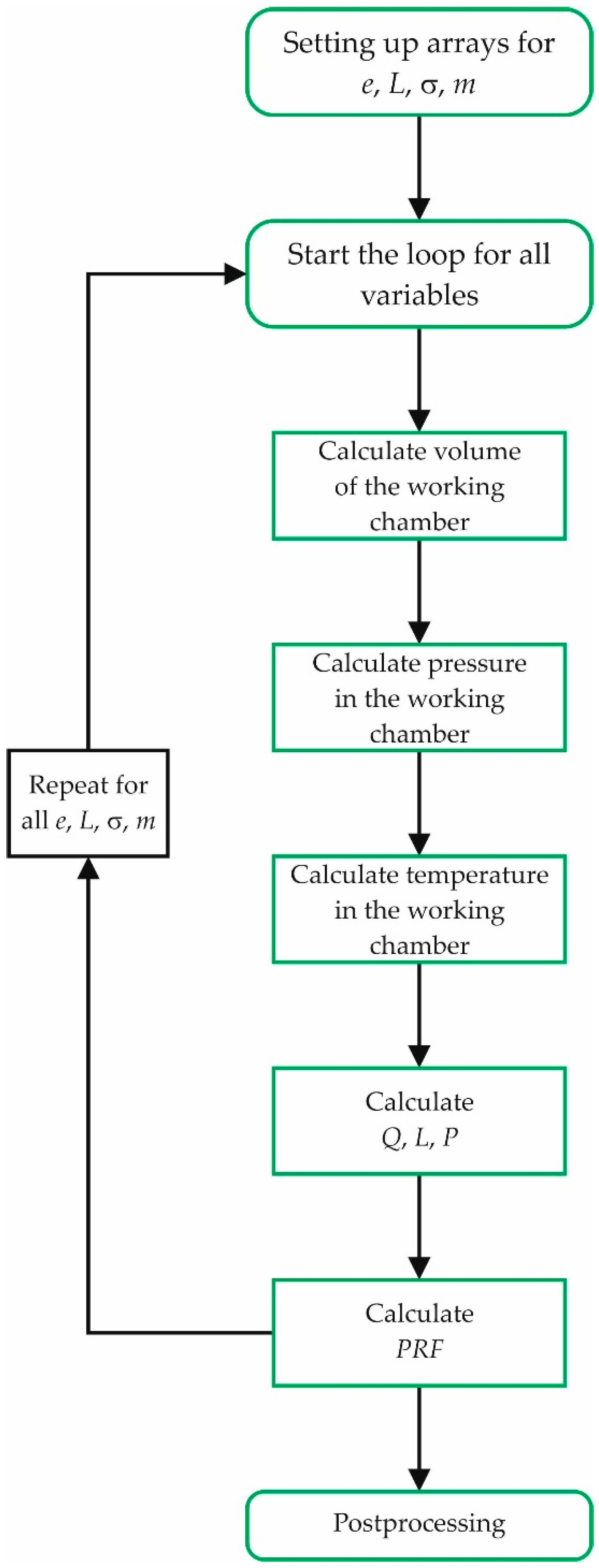
The mathematical model describing the expander working cycle was constructed based on Equations (1)–(15) and was implemented in computer software [
22]. The flowchart of the computational procedure is presented in
Figure 6.
The goal of the analytical modeling was to examine the influence of the following expander characteristics on power output:
Eccentricity e,
Length of the cylinder L,
Expansion ratio σ = ps/pd,
Polytropic exponent m.
These parameters were varied according to arithmetic progression in the following ranges: e = 0.008–0.2R, L = 1.5–3.0R, σ = 2–8, m = 1.333–1.99. As the eccentricity and the length of the expander are functions of a cylinder radius R, calculations were carried out for a fixed R = 0.15 m. Working fluid, treated as a polyatomic ideal gas, was natural gas. Due to methane accounts for 98% of the natural gas, its properties were used in the calculations (RCH4 = 518.33 J/(kg K)). Additionally, it was assumed that clearance volume is equal to zero and pressure fluctuations at the inlet and outlet, caused by valves inertness, are negligible and can be omitted. In each case, the pressure at the outlet was held constant and set to pd = 500 kPa, while rotational speed was equal to n = 3000 rpm.
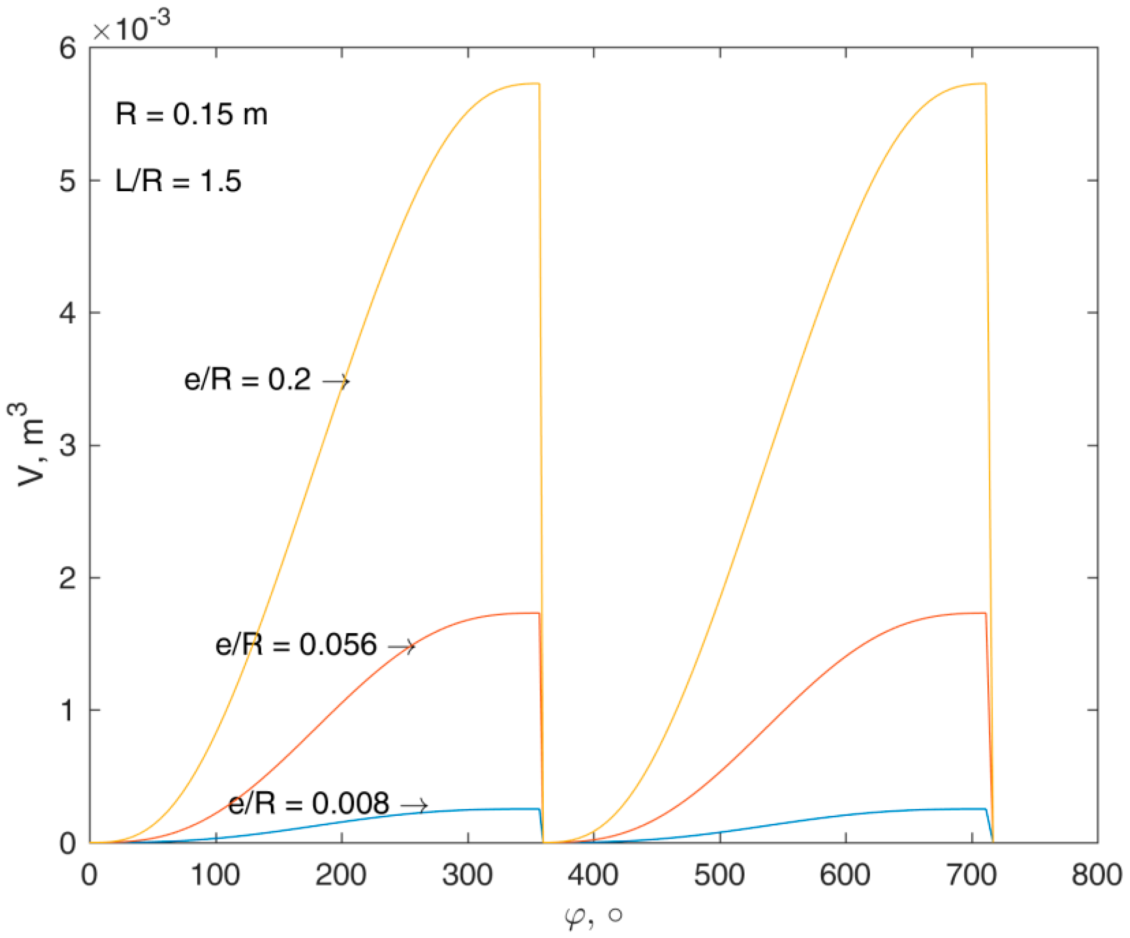
In
Figure 7, the volume of a working chamber versus rotor rotation angle, for different eccentricities, is depicted. As a whole cycle of the expander requires two full revolutions, the volume varies from 0 to
Vmax twice in a one cycle. The volume increases with increasing rotor rotation angle according to an S-shaped curve. With increasing eccentricity, the volume greatly increases, and in the middle range of the half-cycle, linear growth is observed.
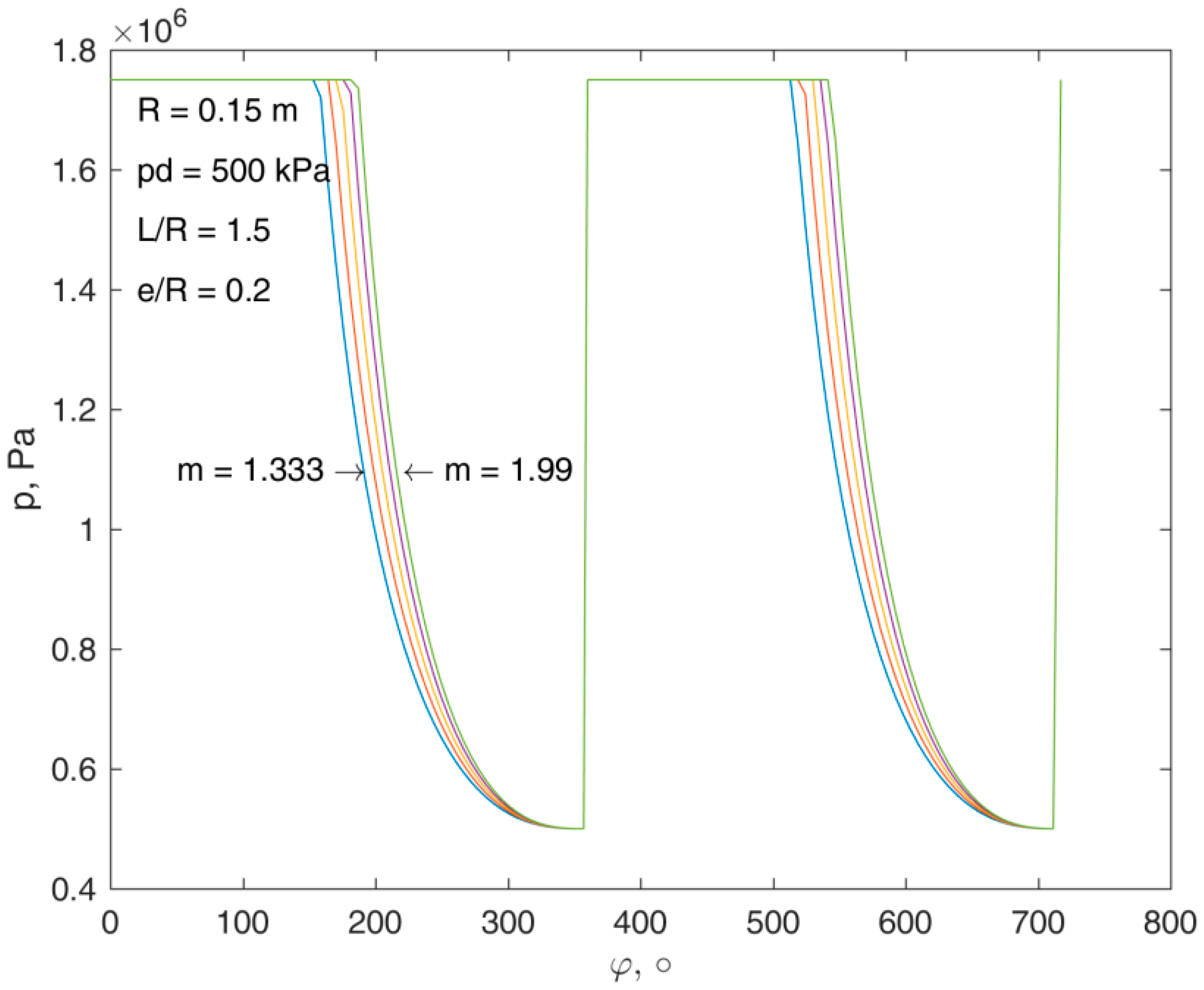
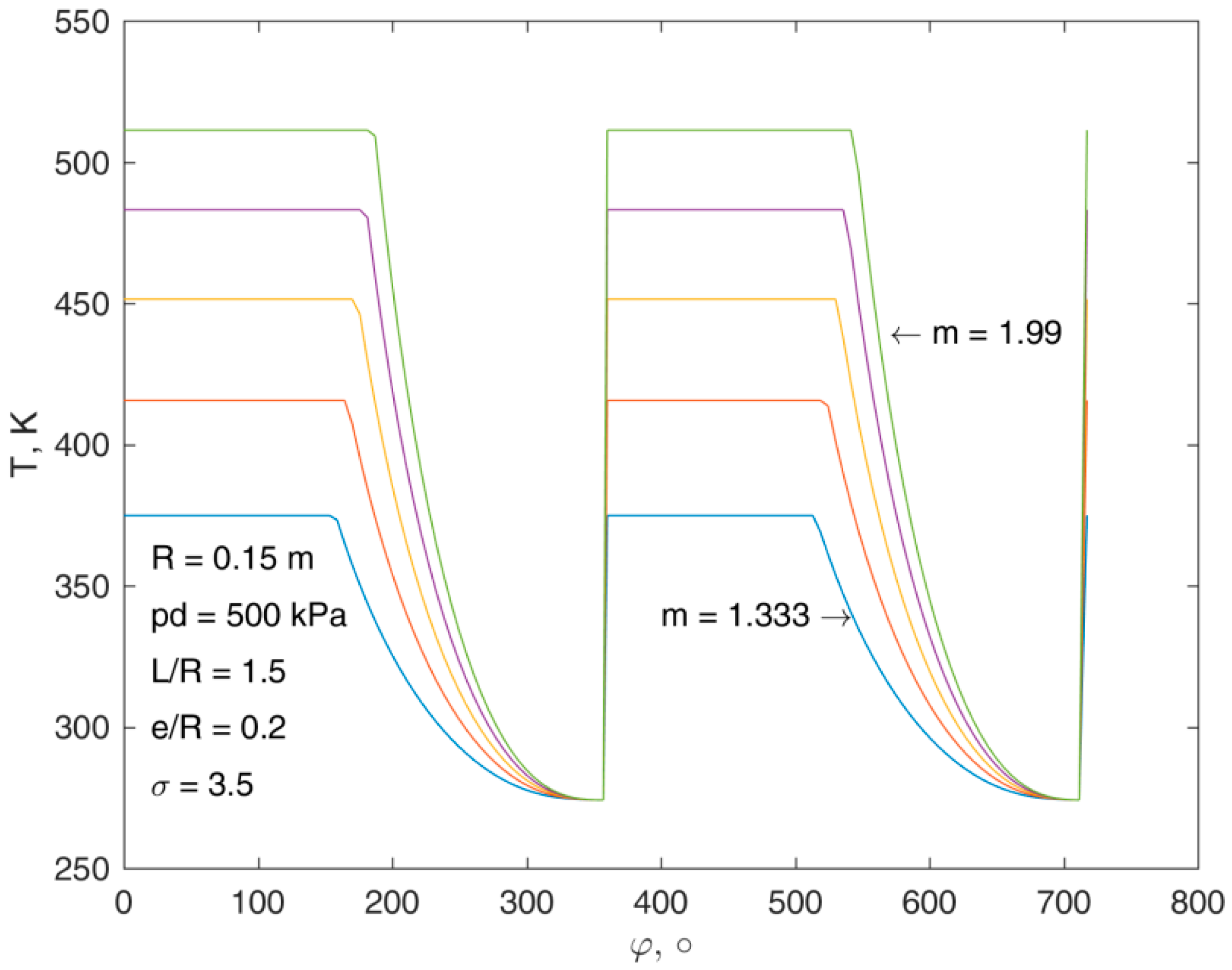
In
Figure 8 and
Figure 9, pressure and temperature distributions versus rotor rotation angle, for different polytropic exponents
m, are presented. The area under the
p-curve was proportional to the indicated work. With increasing polytropic exponent this area also increased. The variation of
m influenced the rotor rotation angle for which inlet valve opened. With increased
m, the inlet valve opened for greater values of rotor rotation angle, i.e., the filling cycle was lengthened. During the filling, both pressure and temperature stayed constant up to the opening of the inlet valve. Then, the expansion process started and pressure decreased. For a fixed
m, temperature decreased from inlet temperature
Ts to a minimal temperature
Tmin after expansion. It can be seen that in
Figure 9,
Ts was very high and increased with increasing
m. This temperature resulted from heat input that had to be provided to the working fluid before the expansion started. Heating was necessary in order to heat up the working fluid to the temperature
Ts for which the temperature of the working fluid after expansion would be higher than the limiting temperature
Tmin. This was done in order to prevent hydrate formation in the gas [
2]. During all calculations,
Tmin was set to 274 K. In
T-chart heat is the area under the
T-curve, and it was observed that with increasing
m, the heat necessary for heating the working fluid increased as well.
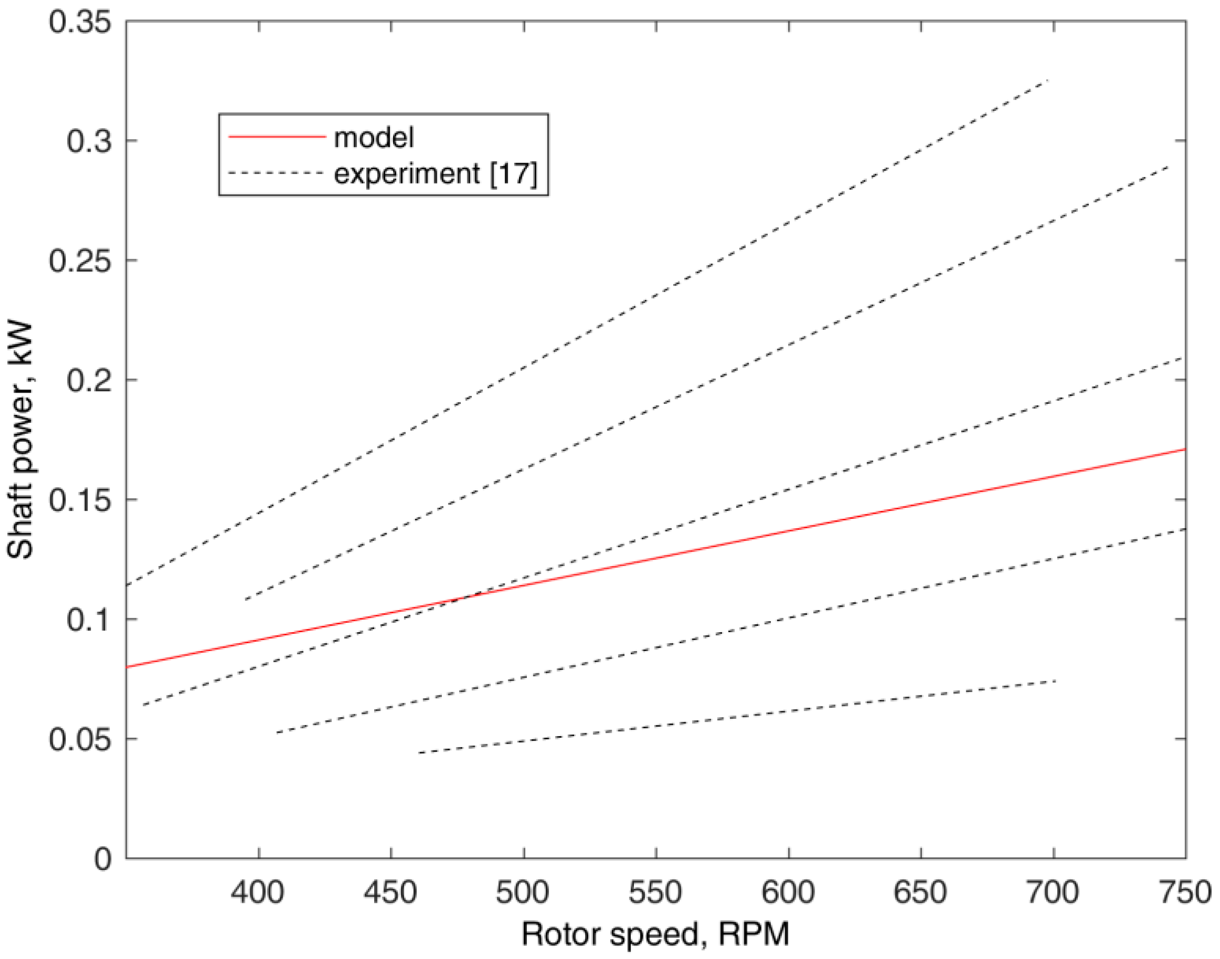
In order to assess the analytical model, the authors decided to compare the obtained results with experimental data presented in the literature. As the use of rolling piston expanders in power systems, and in particular for the expansion of natural gas, is a novel and constantly evolving topic, finding publications containing a sufficient range of experimental data and description of machine geometrical dimensions was difficult. In [
17], the results of experimental investigations on the operating conditions of a rolling piston expander applied in the ORC system were presented together with expanders’ geometrical dimensions. Basing on data reported in [
17] the authors decided to carry out additional computations for R245fa as a working fluid and the same boundary conditions, and the expanders’ geometrical dimensions. For the purpose of the comparison, the shaft rotational speed was simulated in the range of
n = 300–700 rpm, similar to the experiment. The polytropic exponent was assumed as
m = 1.2 which corresponds to the average conditions during the experiment.
Figure 10 shows the comparison of the experimental results reported in [
17] with data obtained from the above described model. As plenty of experimental results were presented in [
17] the authors decided to select and plot in
Figure 10 a set of dotted regression lines which formed the expanders’ working area, and represented the mean values of the experimental characteristics under different experimental conditions (i.e., variable shaft load and mass flow through the expander). Using the model, the authors calculated the output power characteristic (visualized via red solid line in
Figure 10) for the mean values of the experimental parameters. As can be seen in
Figure 10, the obtained via model line fit within the mean range of experimental results, and the order of magnitudes of output power, and the slope of both modeled and experimental characteristics were in good agreement. For this reason it can be stated that the model is a good tool for estimating the power output in rolling piston expanders.
Moreover, in relation to the variation of the working chamber volume, gas pressure, and temperature, the obtained modeling results showed good agreement with experimental and numerical modeling results presented in many publications [
23,
24,
25,
26,
27].
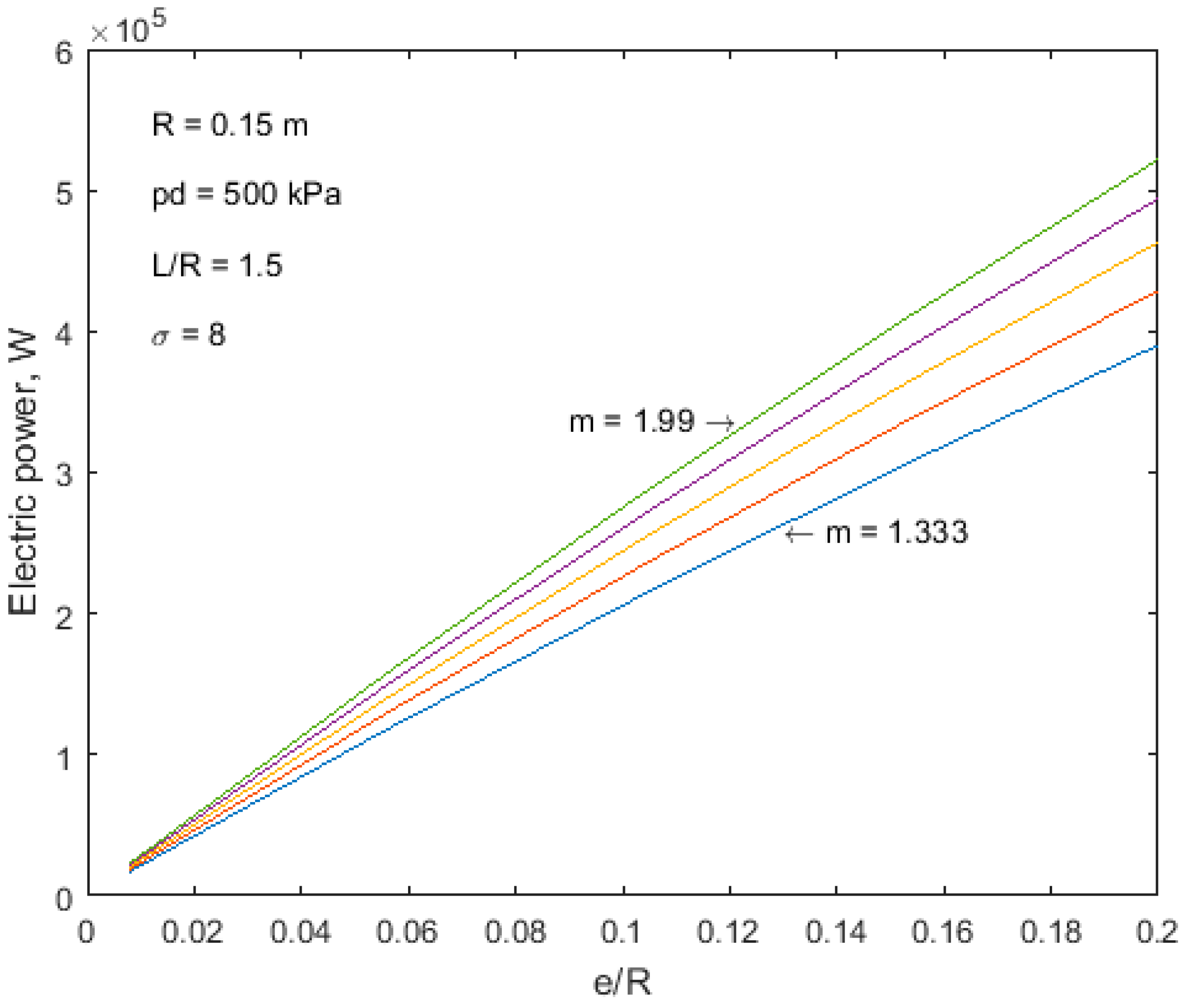
In
Figure 11,
Figure 12 and
Figure 13, an influence of eccentricity, cylinder length and expansion ratio, for different polytropic exponents, is presented correspondingly. Dependence of power on eccentricity and cylinder length was almost linear. Power increased both with an increasing polytropic exponent, and increasing the geometrical characteristic values (eccentricity, cylinder length) of the expander. From
Figure 13, it was observed that for very low polytropic exponents (
m < 1.5) power hardly depended on expansion ratio σ. A visible increase in power with increasing σ was observed for
m > 1.7. For the fixed geometrical dimensions presented, power in the range of 0.1–1.0 MW can be obtained using the rolling piston expander.
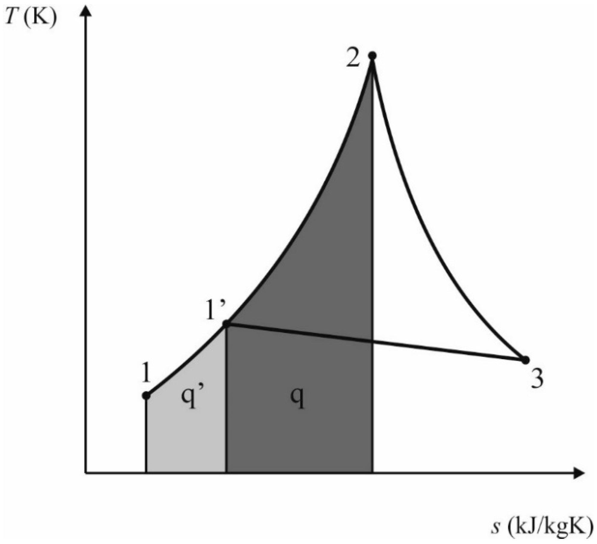
As was stated above, in order to decrease gas pressure, throttling valves in pressure reduction stations are used. However, before a gas is throttled, it has to be heated up to prevent hydrate formation [
2].
Figure 14 shows this processes in the T-s chart. First, gas at the temperature and pressure at Point 1 is isobarically heated up to the temperature at Point 1′. Then, gas is throttled in the valve up to Point 3, by an isenthalpic process. The area under the curve from Point 1 to 1′ represents the heat
q′ that has to be provided to the gas. Usually, a 2–7 K increase of the gas temperature per 1 MPa of the gas pressure is necessary.
In the present study, we propose the utilization of a rolling piston expander as an engine, instead of using a throttling valve, allowing the recovery of power that is lost in a pressure reduction station. However in this case, the gas has to be heated to a higher temperature at Point 2, to be able to expand it politropically to the temperature
Tmin at Point 3. This process is represented by successive points 1–2–3 in
Figure 14. The area under the curve from Point 1 to 2 represents heat
q that has to be provided to the gas during isobaric heating, when a rolling piston is used.
This means that in order to obtain work, one has to input more heat, compared to the case of throttling valve usage. Thus, the natural question to ask is when such a process (heating the working fluid and then expanding it in the rolling piston machine) would be profitable. To assess this issue, a novel coefficient was formulated and called the Power Recovery Factor (
PRF), which is defined as the ratio of work output
lt2–3 to heat input, and is expressed as follows
A plot of the
PRF versus
m for different expansion ratios σ is presented in
Figure 15. For the fixed outlet pressure
pd, with increasing inlet pressure
ps,
PRF decreases. This means, that for higher inlet pressures, temperature at Point 2 strongly increases, and thus heat input is higher. For very high pressures (σ ≥ 8), usage of the rolling piston is justified only for
m ≤ 1.4. For processes close to adiabatic conditions (
m → k)
PRF increases. One can see that for low expansion ratios (σ = 2) and a small polytropic exponent (
m < 1.4), almost 60% of work can be recovered.


