1. Introduction
Proportional-Integral-Derivative (PID) controllers are widely used in industrial process control. The three-mode controller contains a proportional, an integral, and a derivative term. The popularity of a PID controller can be attributed to its good performance and functional simplicity, which allows engineers to operate it in a simple and straightforward manner. For example, the three controller gains can be chosen independently by an engineer, based on one’s experience or through some simple selection methods such as the classical tuning rules proposed by Ziegler-Nichols [
1]. For simplicity of the controller design, a PI or PD controller are also popular for practical applications. A PI controller can add damping to a system and reduce steady-state error, but yields penalized rise time and settling time. A PD controller also adds damping and reliably predicts and reduces large overshoots, but does not improve the steady-state error. Thus, for complete design considerations, a PID controller should be employed to obtain a desirable system response in settling time, steady-state error, and overshoot.
On the other hand, since Lotfi Zadeh rediscovered and promoted fuzziness in 1965, the subsequent two fuzzy inference techniques proposed by Mamdani [
2] and Sugeno [
3] have inspired research in fuzzy logic controllers (FLC). The heuristic fuzzy rules, which reflect the experience of human experts, can be applied to plants that are difficult to model mathematically. The most common FLCs are PI-type or PD-type controllers [
4,
5,
6], which possess the same characteristics as traditional PI or PD controllers, respectively. Moreover, they exhibit superior applicability compared with traditional PI or PD controllers [
7].
The FLC commonly outperforms the corresponding PI, PD, or PID controller because a FLC is a nonlinear controller, while a PI, PD, or PID controller is linear. This raises the equivalence problem between a fuzzy PID controller and a conventional PID controller. It is well known that the design of fuzzy rules for a FLC requires expert knowledge, and those who are skilled in conventional PID controller design are then qualified as the experts. For a well-tuned conventional PID controller, design work is saved by replacing it with an equivalent linear FLC, then improving the performance over a conventional PID controller by slightly modifying the fuzzy rules.
Moon [
8] revealed that when a PI controller is given, an FLC output is identical to that of the PI controller by using specified fuzzy logic operations. However, Moon’s design is limited to PI controllers, and the design procedure is not clear enough. Several studies have investigated fuzzy PID controller structures, by taking different combinations of the fuzzy PID structural elements [
9,
10,
11]. This involves a large number of parameters in defining the fuzzy rule base. Manikandan et al. [
12] presented a design for an equivalent fuzzy PID controller from the conventional PID controller, but the tuning procedure was too complicated and the resulting FLC was not purely linear according to the control surface view of the study. Therefore, the equivalence problem between different systems is very crucial to many research fields [
13].
The objective of the study is to extend the significant results derived by Moon [
8] by examining the equivalence relationship and design procedure between a traditional PID controller and its corresponding equivalent FLC. This research proposes an equivalent fuzzy PID controller which has a simple PID structure design with a 3-dimensional fuzzy rule table, instead of the combination of different fuzzy PID structural elements or a hybrid controller structure [
14]. Moreover, to achieve optimal control performance for a FLC, some artificial intelligent techniques such as Genetic Algorithm and Neural Network are efficient approaches [
15,
16]. This inspires us in the future to propose nonlinear factors for tuning the membership functions to develop an optimal fuzzy PID controller design with less parameters.
This study presents the equivalent fuzzy PID controller design (
Section 2), followed by the simulation results of Matlab/Simulink for verifying the proposed design (
Section 3). Finally, the concluding remarks and implementation issues (
Section 4) are discussed.
2. The Equivalent Fuzzy PID Controller Design
The fuzzy PID controller design proposed is equivalent to a conventional PID controller, and is derived from the equivalence equations. First, for a conventional PID controller, the equation for output
in the time domain is
where the controller provides a proportional term, an integration term, and a derivative term. The output
and the three inputs
,
, and
can be thought as fuzzy variables in the FLC design. It is assumed that the operating ranges for
,
,
, and
are
,
,
, and
, respectively.
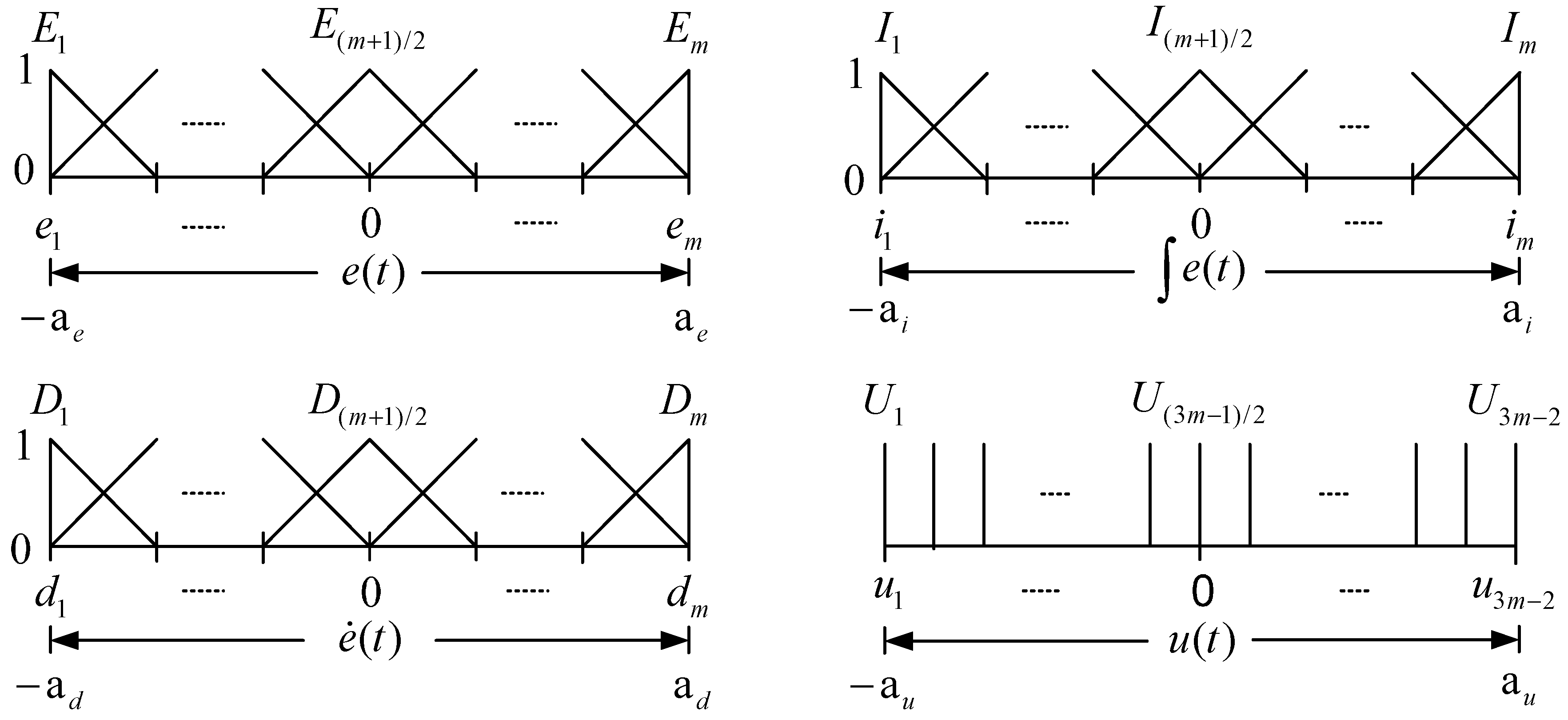
Figure 1 shows the membership functions for graphically defining the four fuzzy variables.
As shown in
Figure 1, the
fuzzy sets are equally-spaced and triangular-shaped for each input fuzzy variable
,
, or
. On the other hand, the output fuzzy variable
is fuzzified by
singleton membership functions. Let
,
,
, and
denote the center of fuzzy sets
,
,
, and
, respectively, so that we obtain the following equations
We further define the distance between
and
as
which will be used in later equation simplification. Based on the above fuzzy variables definition, the expression of antecedent (
IF) and consequent (
THEN) for each fuzzy rule is defined as
where three input fuzzy variables
,
, and
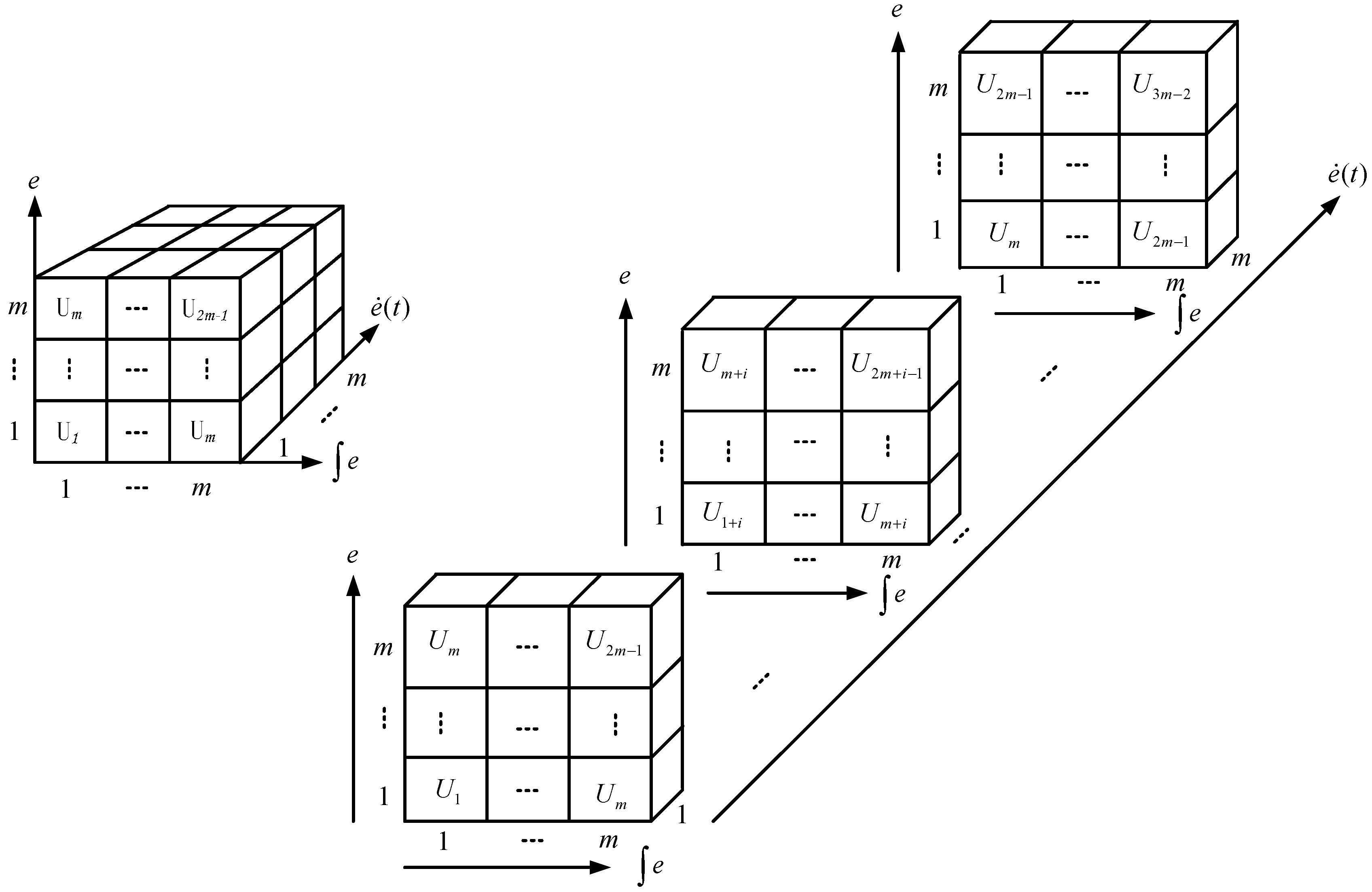
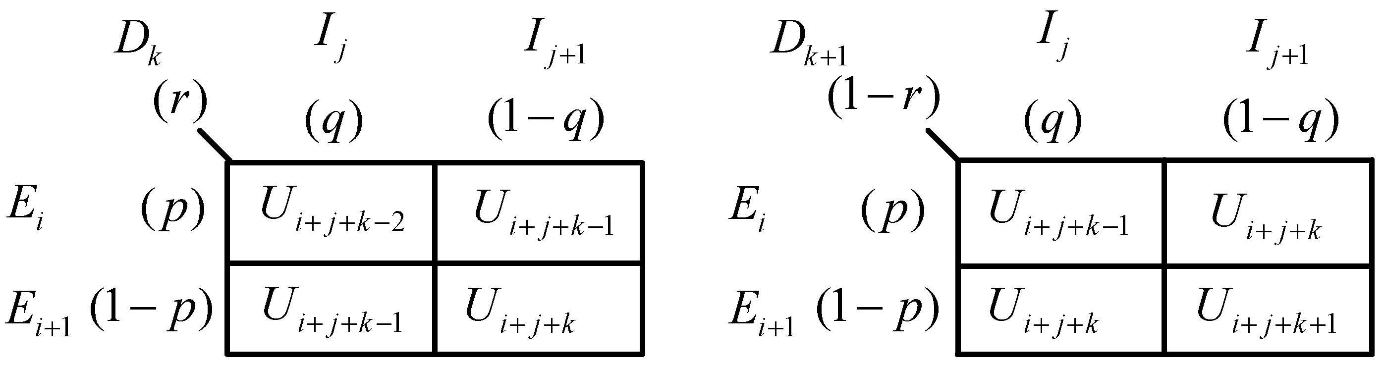
are taken into consideration simultaneously. In the proposed linear fuzzy PID design, the overall fuzzy rules for the three-by-one system can be represented by the sliced cube fuzzy associative memory (FAM), as shown in
Figure 2. Furthermore, we have the following equation related to Equation (5)
Subsequently, verification of the proposed design is done by applying the Sugeno-style inference, the resulting controller output
for controller inputs
,
, and
can be calculated by carrying out an aggregation of the form
where the product operation rule is used for the fuzzy logic implications and the center of gravity (COG) is applied for the defuzzification process. It is determined that there is at most, eight rules to be fired for any controller inputs
,
, and
. To clarify, consider the crisp input
corresponding to the membership functions
and
to the degrees of
and
, respectively. Similarly, consider that
maps the membership functions
and
to the degrees of
and
, respectively. Also, it is assumed that
has degrees of
and
with respect to the membership functions
and
. Based on the above assumption, the membership degrees
,
, and
can be described as
The fired eight rules are listed below, and
Figure 3 is an illustration for these eight rules.
As shown in Equation (7), the crisp output can be evaluated as by taking the weighted average of the eight rules consequents. Thus, the denominator of with 8 terms will be finally reduced to 1, as shown in Equation (9).
On the other hand, the nominator part of
with 8 terms is obtained by
which can also be confirmed in
Figure 3. In order to simplify Equation (10), we use a method of applying Equation (4) and defining
. Then Equation (10) can be reduced to
where Equation (3) is also applied.
By substituting Equation (2) into Equation (8), we can rewrite the membership degrees
,
, and
as
With Equation (12) substituted into Equation (11),
is finally obtained as follows
Thus, the crisp output
of the proposed linear FLC is given by
which implies a linear PID controller with
Equation (15) shows that if a FLC design is based on the fuzzy knowledge from
Figure 2 and the defuzzification process in Equation (7), then it will yield a linear PID controller and the resulting PID parameters have no relation with
, the number of membership functions, but is strongly correlated to the operating ranges of the control input/output. With the derived important equivalence result, the designer can obtain a FLC design prototype based on a conventional PID controller design.
In practical application, a FLC will be finished by digital implementation. When considering a digital PID controllers, the equation for the output
at each sampling time will be
where
is the sampling time. In the subsequent section, the performance of the FLC implemented in digital form is verified.
3. Simulation Results
In this section, the proposed equivalence relationship is verified by use of Matlab/Simulink. A three-order controlled plant is employed with transfer function [
17], which is shown below
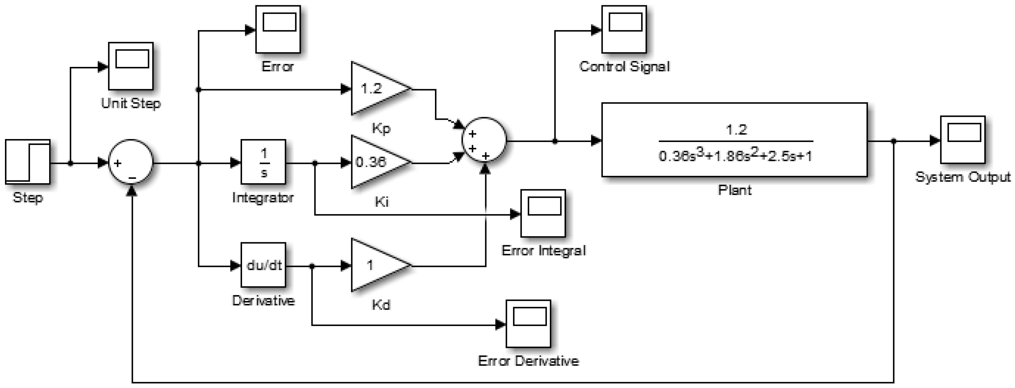
A conventional PID controller design for
with
,
, and
, which was simulated by Simulink is shown in
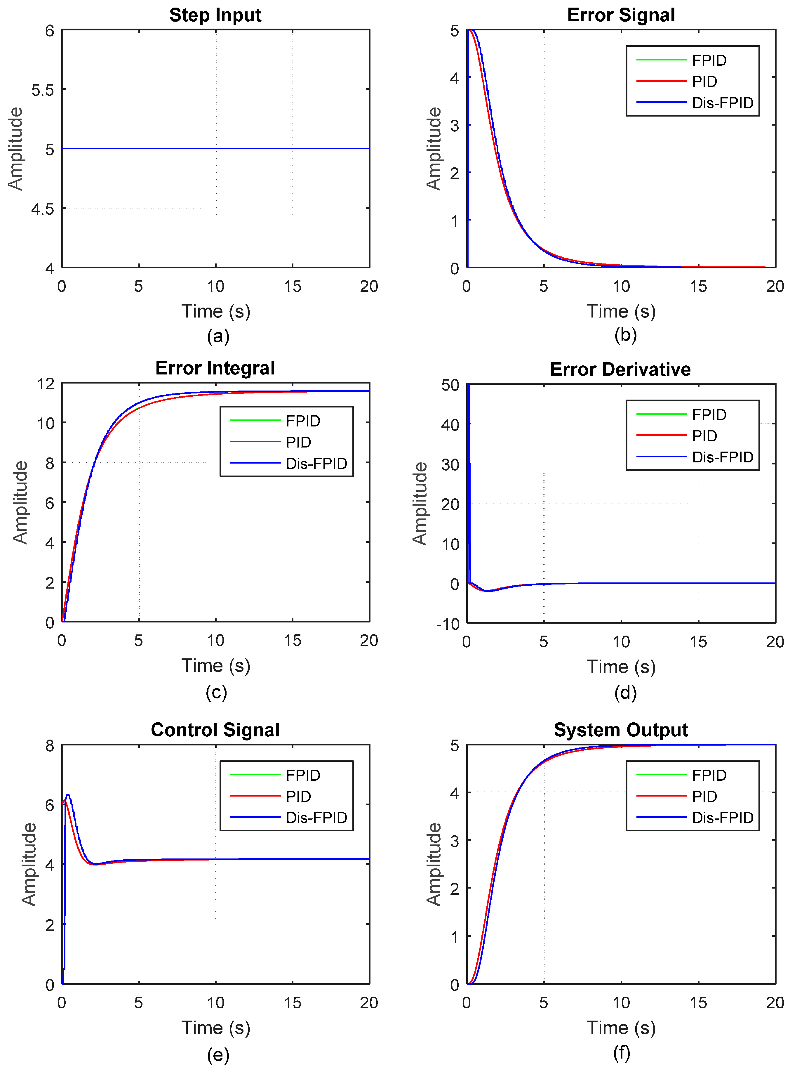
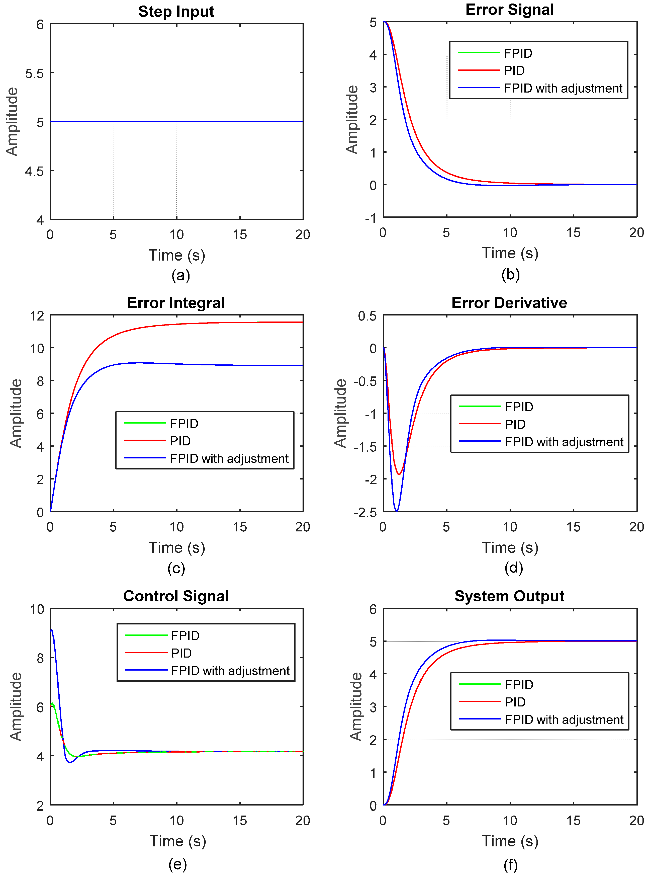
Figure 4, and the PID controller can simultaneously improve system responses in rise time, settling time, steady-state error, and overshoot. The magnitude of the input step signal is set as 5, and the resulting error signal, error integral, error derivative, control signal, and system output are shown in
Figure 5 (red line).
Subsequently, we built the equivalent FLC based on the above conventional PID controller design according to the derived equivalence equation. By observing the system responses
,
,
, and
with the above conventional PID controller in
Figure 5 (red line), the operating ranges
,
,
, and
can be defined in accordance with Equation (15), as the procedure below shows.
is set as , which is the range for .
is set as to satisfy .
is set as to satisfy .
is set as to satisfy .
For this case, it shows good results in defining the operating ranges. Furthermore, this is not a limitation as there are four parameters
,
,
, and
for adjustment to satisfy the three control parameters
,
, and
in Equation (15). The Fuzzy Logic Designer in Matlab/Simulink was applied for the equivalent FLC design and simulation.
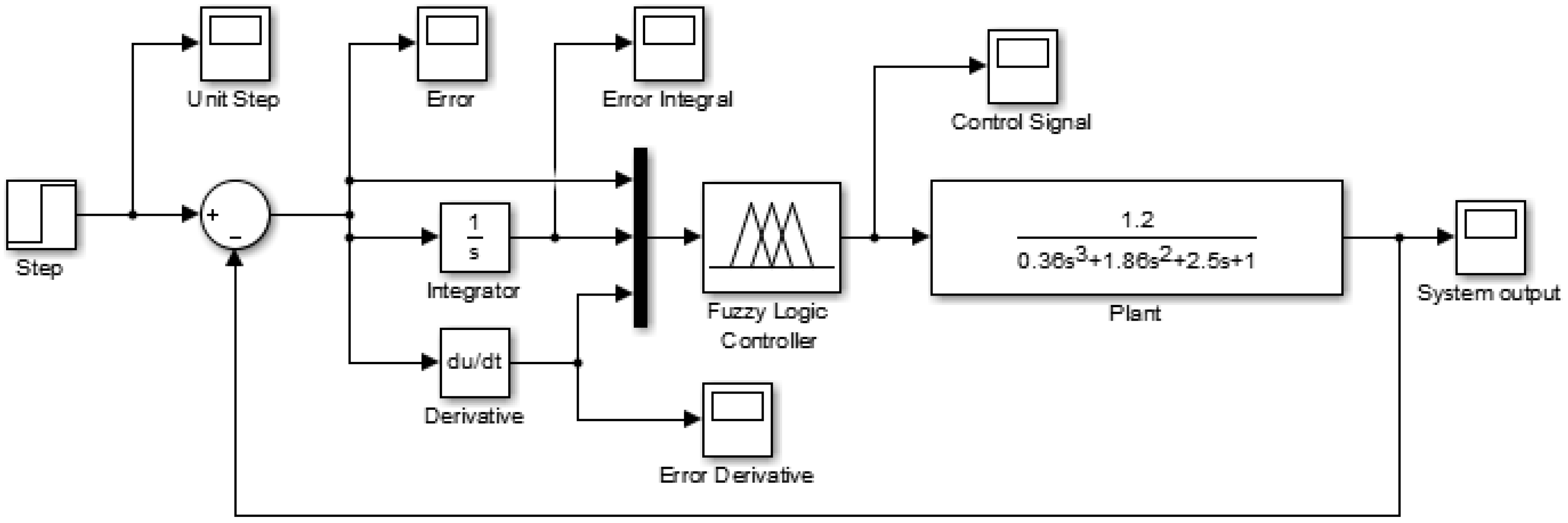
Figure 6 shows the feedback control structure.
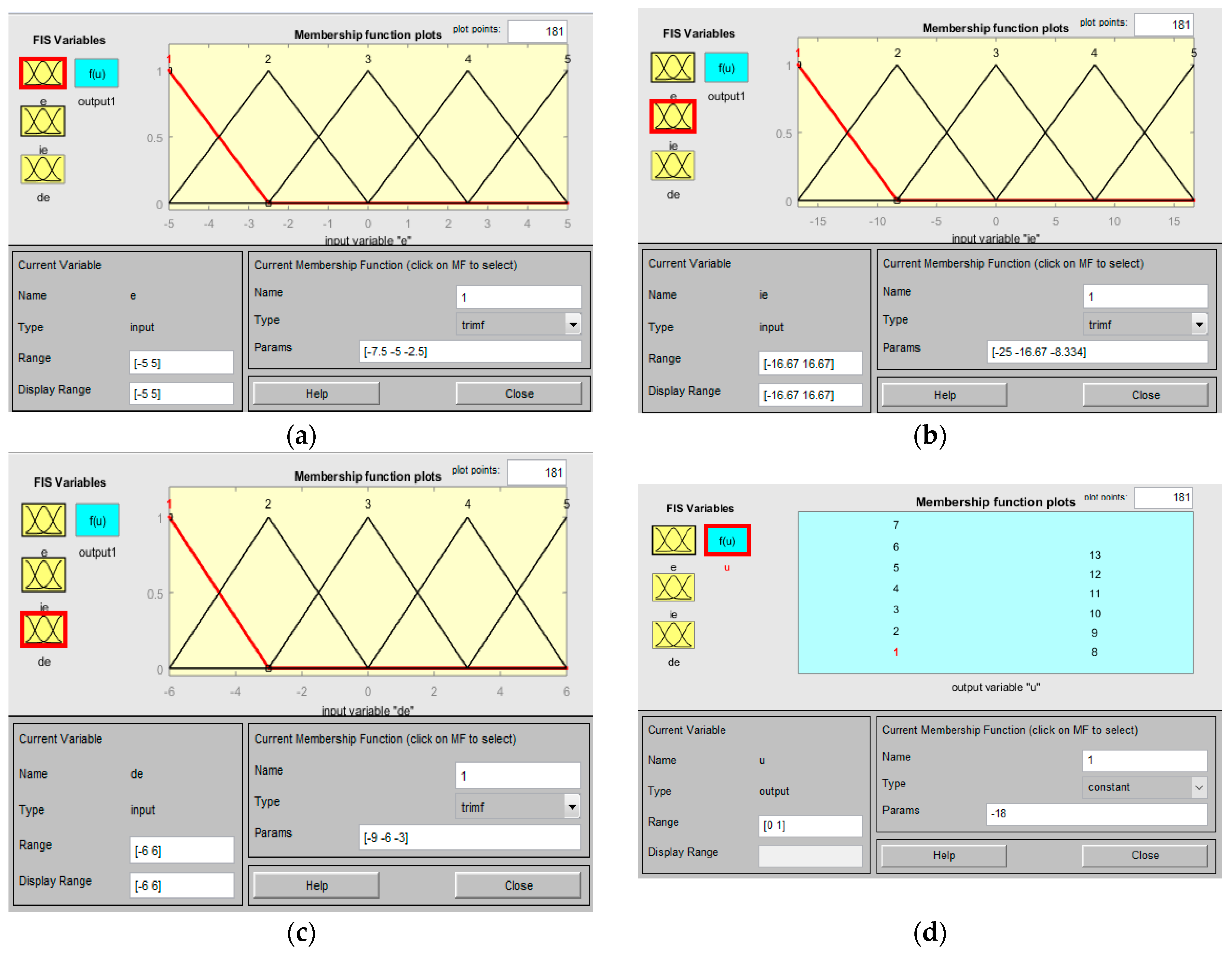
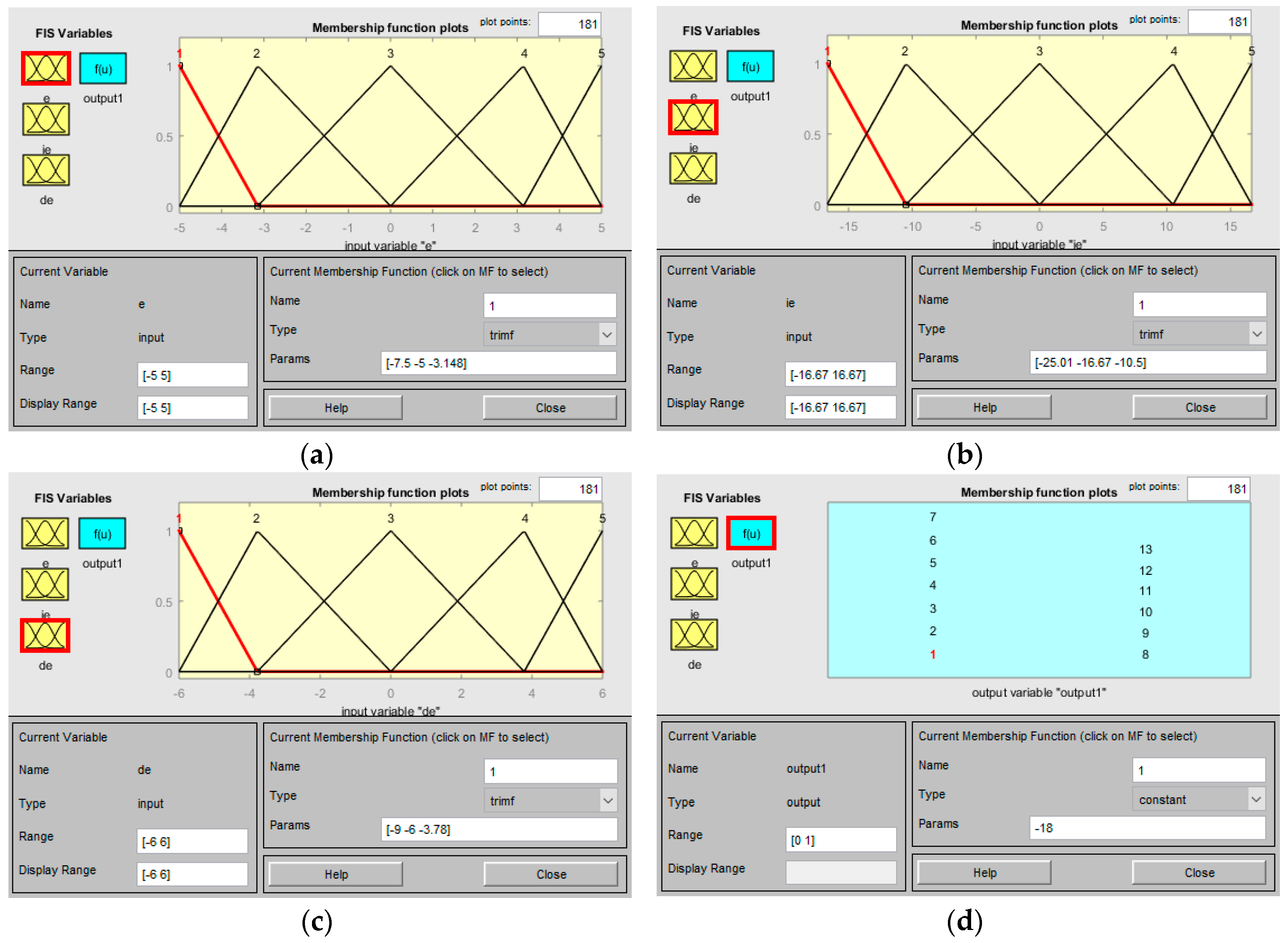
The “FIS Type” of the FLC design in
Figure 6 should be set as “Sugeno”. Based on the above operating ranges of four fuzzy variables, the corresponding membership functions can be defined by
Figure 1. The parameter
was set as 5, resulting in 5 fuzzy sets, which are equally-spaced and triangular-shaped, for each input fuzzy variable
,
, or
. On the other hand, the output fuzzy variable
is fuzzified by 13 singleton membership functions with singleton values −18, −15, −12, …, −3, 0, 3, …, 12, 15, and 18.
Figure 7 shows the settings of all the membership functions in the Matlab environment. The 125 fuzzy rules are defined according to the knowledge base in
Figure 2, and the resulting system input and responses are shown in
Figure 5 (green line). However, it is found that the system responses with a green line cannot be examined, which is due to the overlap of system responses in the red line. In
Figure 5, the green lines (responses by the equivalent FLC) were plotted prior to the red lines (responses by the PID controller). On the contrary, if we plot system responses by the PID controller (red line) first, it will turn out that all the red responses are covered by the latter green responses in the equivalent FLC. This verifies the proposed equivalence relationship between the PID controller and the equivalent FLC.
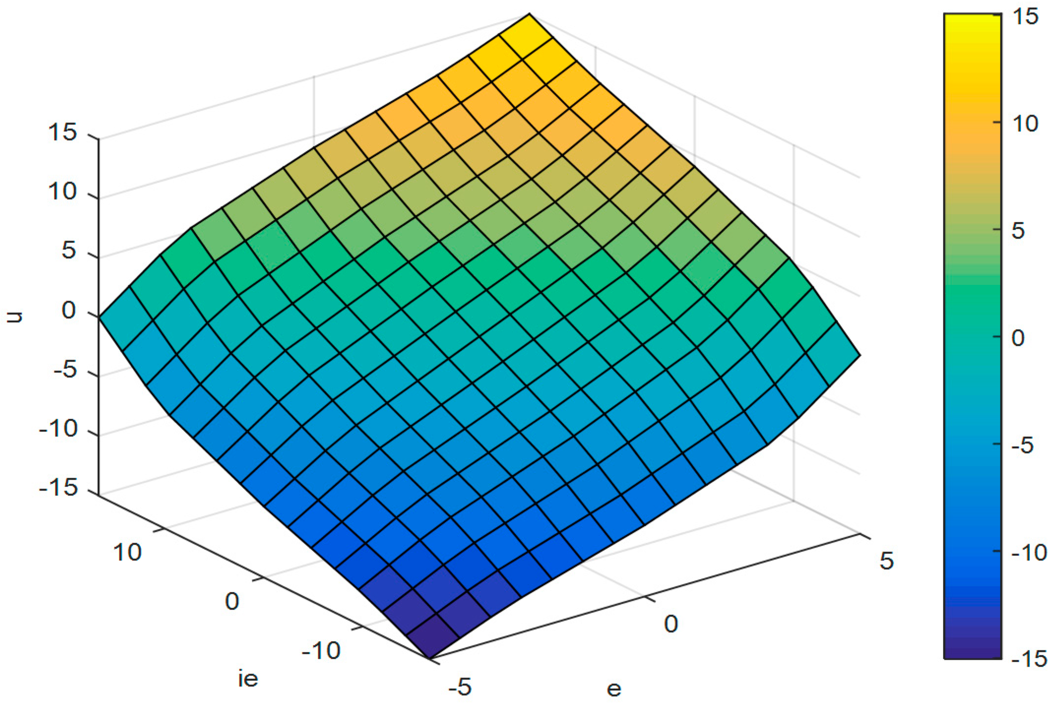
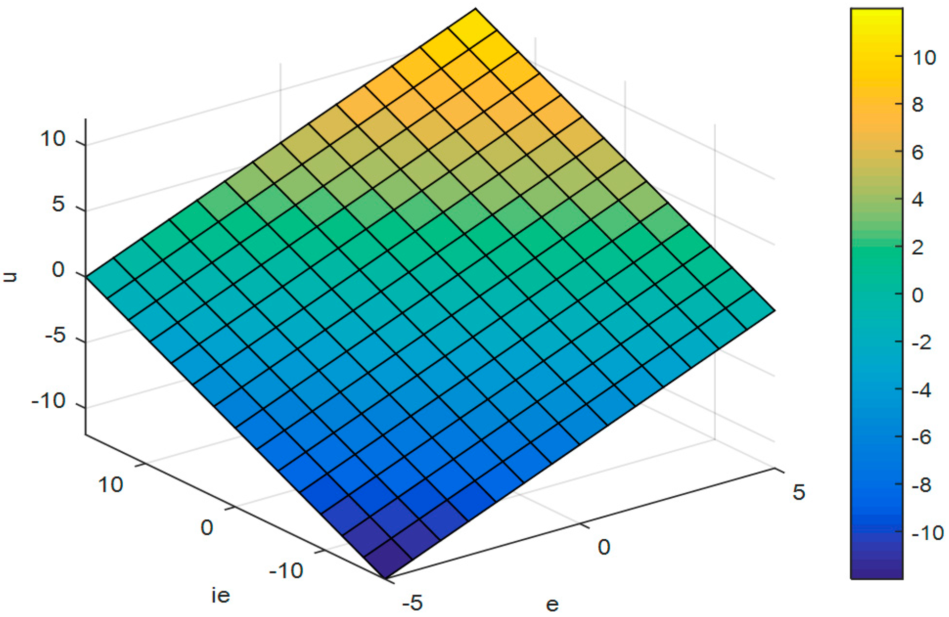
Figure 8 further shows the linearity of the equivalent fuzzy PID controller with the control surface view under
= 0.36.
For the equivalent FLC-controlled system in
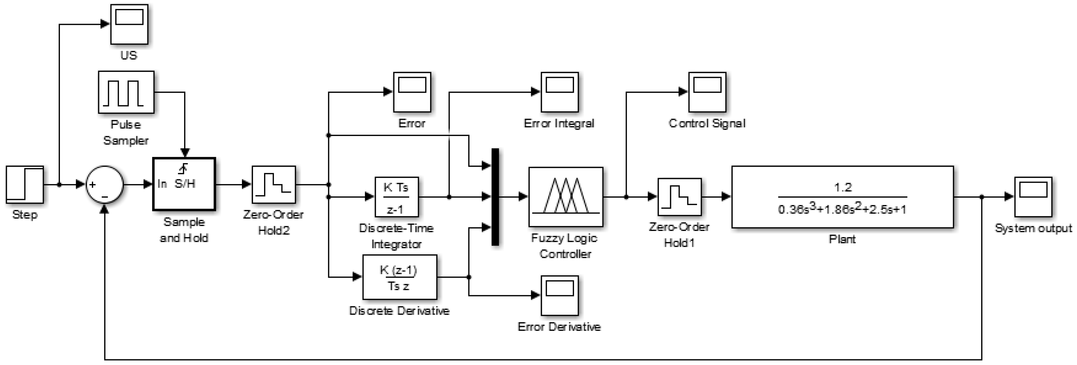
Figure 6, the Matlab/Simulink finishes the simulation in a manner of a continuous-time system. Alternatively, for practical applications, a FLC could be implemented in a discrete form. Therefore, to enhance the applicability of this research, the Sample and Hold unit and the Zero Order Hold unit, which can be used to model A/D (analog-to-digital) and D/A (digital-to-analog) converters, are added to make a discretized FLC, as shown in
Figure 9. It must be noted that the Fuzzy Logic Controller in
Figure 6 and
Figure 9 are identical. So, in
Figure 9, the gain (
K) in the “Discrete-Time Integrator” or “Discrete Derivative” does not denote
or
, and is set as 1. The system input and the resulting responses (blue line) are shown in
Figure 5, with sampling period
set as 0.1 s. Simulation results show the equivalent FLC implemented in a discrete form have similar responses compared with the conventional PID controller. If the sampling period
is set to a smaller value, the closer of the two responses will be obtained.
We slightly adjusted the membership functions (MFs) of the equivalent FLC design in
Figure 7. It could be found that MFs are no longer equally-spaced, which implies that the FLC has become nonlinear, as shown in
Figure 10. The 13 singleton values for the output fuzzy variable
are −18, −16.91, −15.05, −12.44, −9.05, −4.91, 0, 4.91, 9.05, 12.44, 15.05, 16.91, and 18.
Figure 11 shows that the control surface view is no longer a plane. The resulting error signal, error integral, error derivative, control signal, and system output are shown in
Figure 12 (blue line), and can be compared with the previous PID controller, and the equivalent FLC (red lines for both).
Table 1 summarizes the response performance, including the rise time (
Tr), the settling time (
Ts), the percentage overshoot (
P.O.), and the steady-state error (
Ess), of the three controllers in
Figure 12. Which controller has better performance cannot be determined since the performance criterion is not defined. But based on this study, a fuzzy PID controller may outperform a conventional PID controller quickly by fine-tuning the MFs of the fuzzy variables.
We have found that some learning-based techniques or evolutionary algorithms have been applied in the optimal FLC design [
14,
15,
16]. Experienced researchers should agree on the importance of setting initial values or weights in the learning system, which will greatly influence the learning results and convergence speed. With the proposed equivalence relationship, one can easily and quickly obtain a fuzzy PID controller through a conventional PID controller design, then the derived equivalent FLC can be set as one of the initial designs. This process will result in the optimal FLC design in an efficient way.


