
Methodological Considerations of Using Thermoelectrics with Fin Heat Sinks for Cooling Applications


Abstract
:1. Introduction
2. Materials and Methods
2.1. Thermal Resistance Model
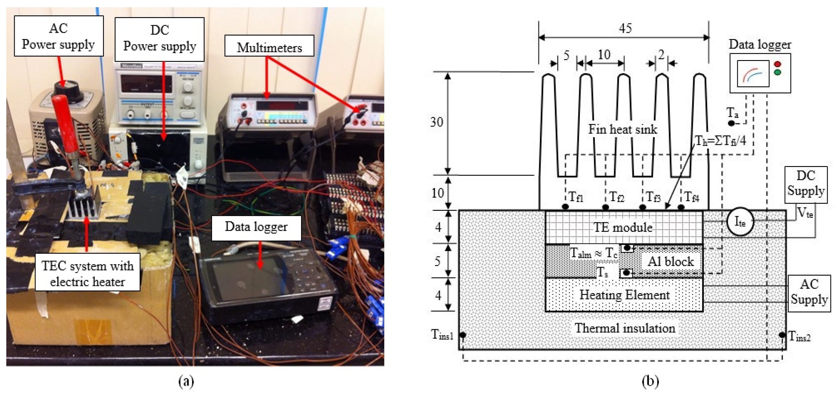
2.2. Experimental Procedure
3. Results and Discussion
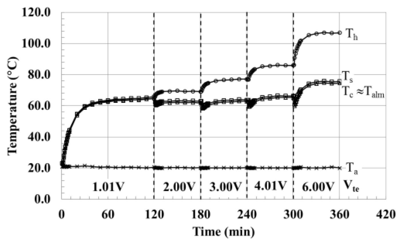
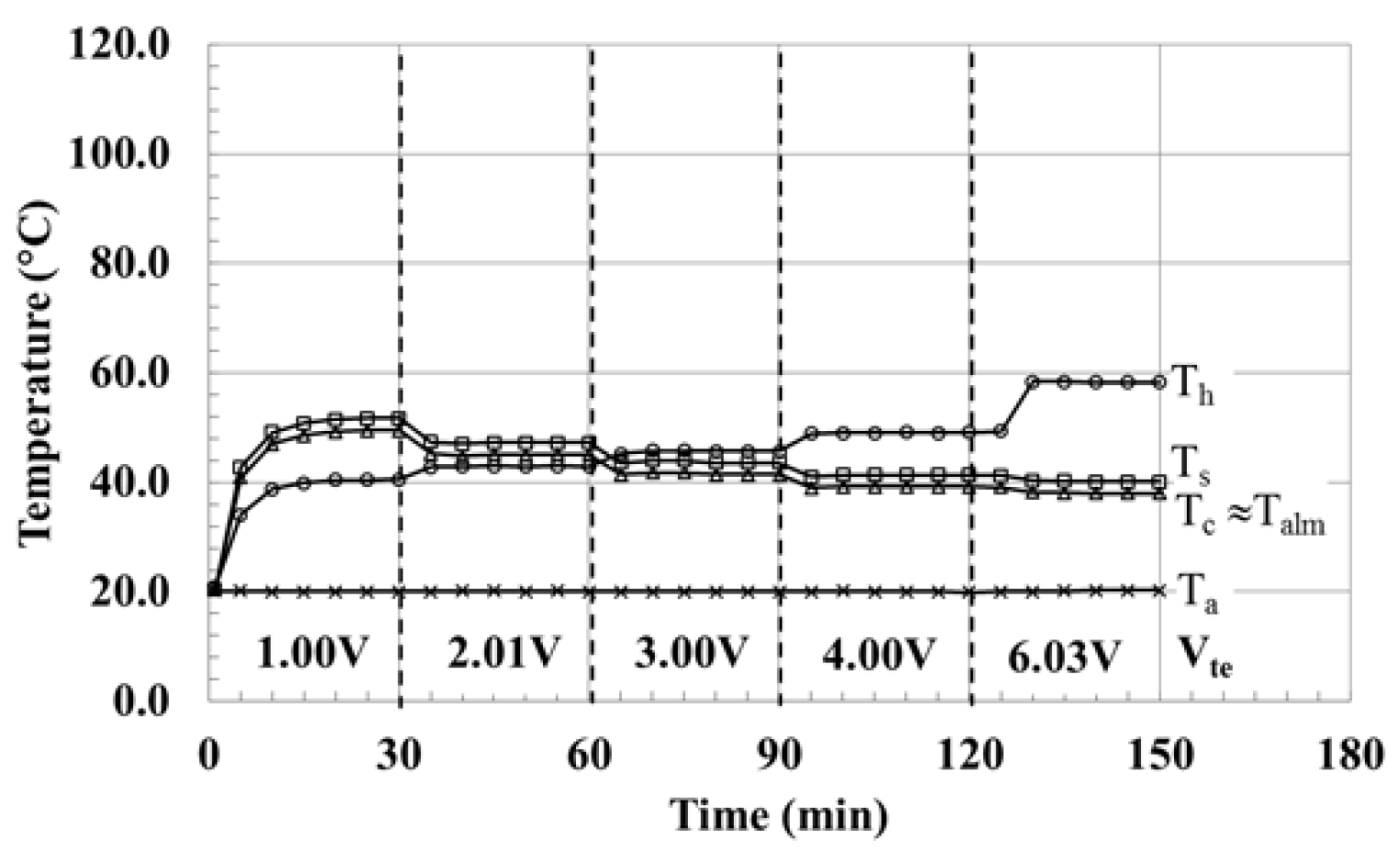
- Temperatures of Th, Ts, and Tc are plotted for the first 120 min and, every 60 min thereafter. The results showed that steady state is achieved after 2 h at the low TE voltage run of 1 V while it took only about an hour at the higher TE voltage >2 V.
- Heat source temperature (Ts) is higher than cold side temperature (Tc) by about 1 °C. This was attributed to the temperature diffference across the thin aluminum block, calcualted to be around 1 °C.
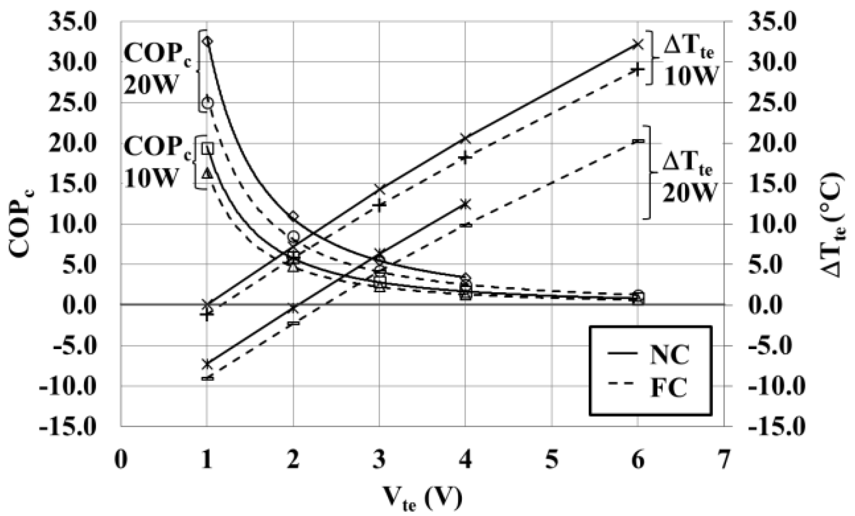
- Temperature difference between hot and cold sides of the TE (Th − Tc) is about 36 °C at the low-power input of 10W and about 12 °C at the higher power input of 20W. Temperature difference decreases with TE power input (Pte).
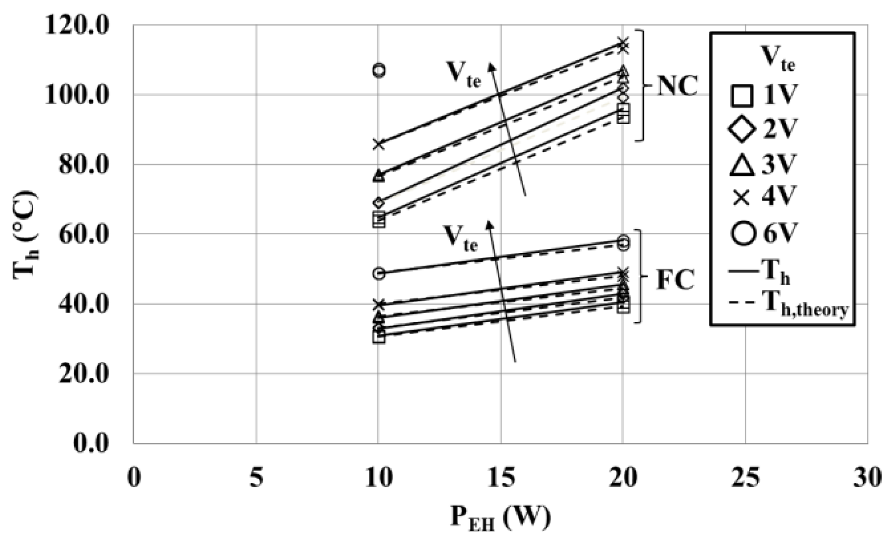
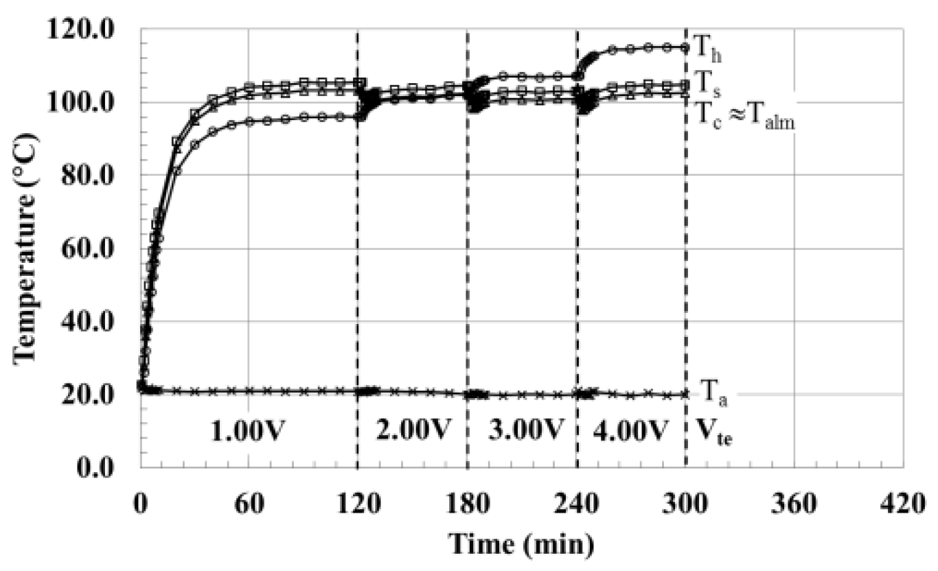
- Heat source temperature (Ts) increases with power input (PEH) from 73 °C at 10 W to 104 °C at 20 W.
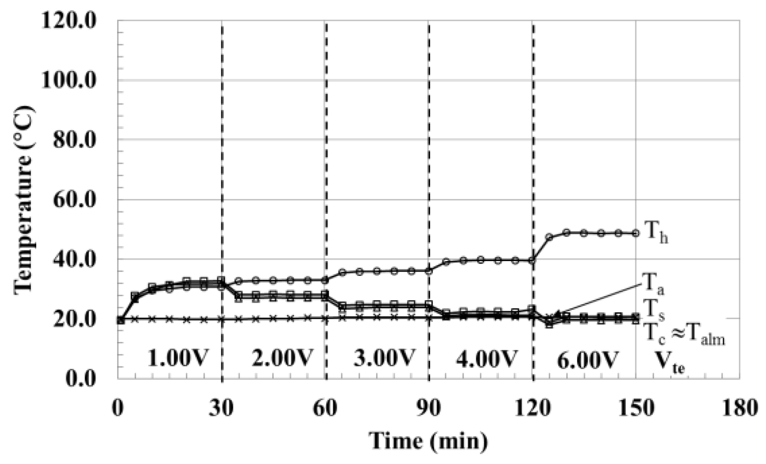
- Steady-state is achieved earlier under FC compared to NC, i.e., after about 30 min, compared to 120 min and 60 min under NC.
- Heat source temperature (Ts) is higher than the cold side temperature (Tc) by about 1 °C. A similar difference is observed under NC showing that the contact thermal resistance does not change with convection.
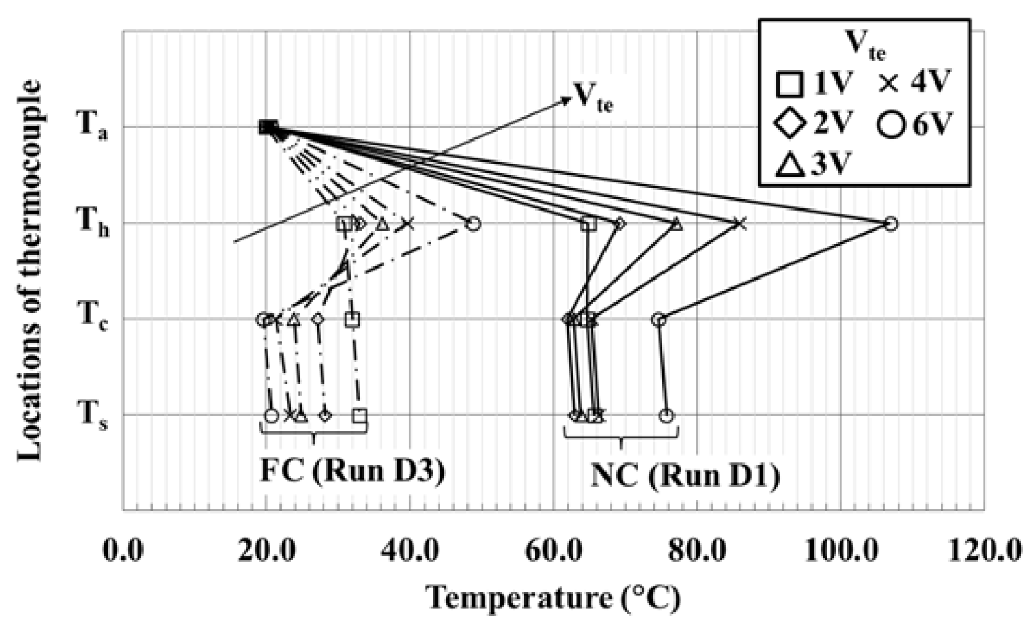
- Cold side temperature (Tc) decreases with an increase in TE applied voltage (Vte) as expected.
- The temperature difference (Th − Tc) between hot and cold sides increase with TE applied voltage (Vte) as expected.
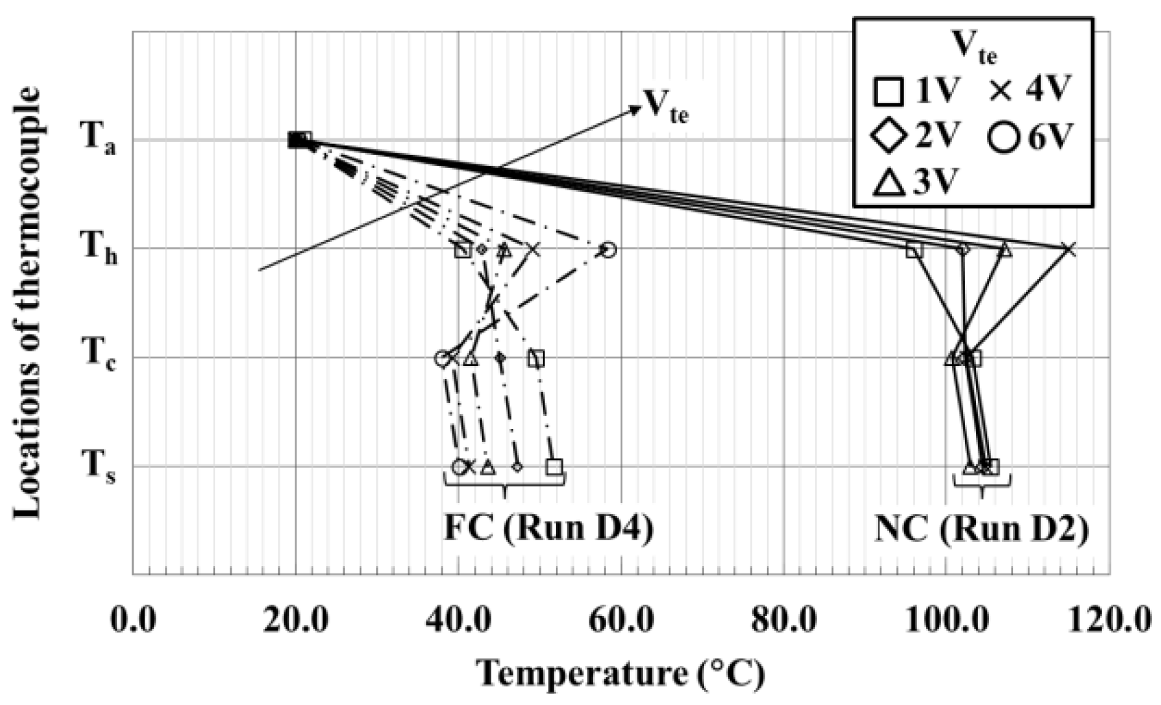
- Heat source temperature (Ts) wasbrought below, or to, ambient temperature (Ta) when power input (PEH) to the heat source was at 10 W and TE input voltage (Vte) was at 6 V.
- Heat source temperature (Ts) roseto about 40 °C when the heat source power input (PEH) was increased to 20 W.
- The temperature difference between TE hot (Th) and cold (Tc) sides was lower at the higher power input of 20 W, comapred to 10 W.
- All temperatures are lower under FC cooling because of higher cooling heat transfer rates during FC air cooling mode as expected.
- Hot side (Th) temperatures increase with an increase in the applied TE voltage (Vte).
- Cold side (Tc) temperatures decrease with an increase in the applied TE voltage (Vte).
- As a result, the temperature difference between hot and cold sides (Th − Tc) increase with applied TE voltage (Vte).
- At low TE applied voltage (Vte), the TE cold side (Tc) could be higher than the hot side (Th). This is because of the insufficient TE power supply to generate a sufficient temperature differential to enable the TE to function.
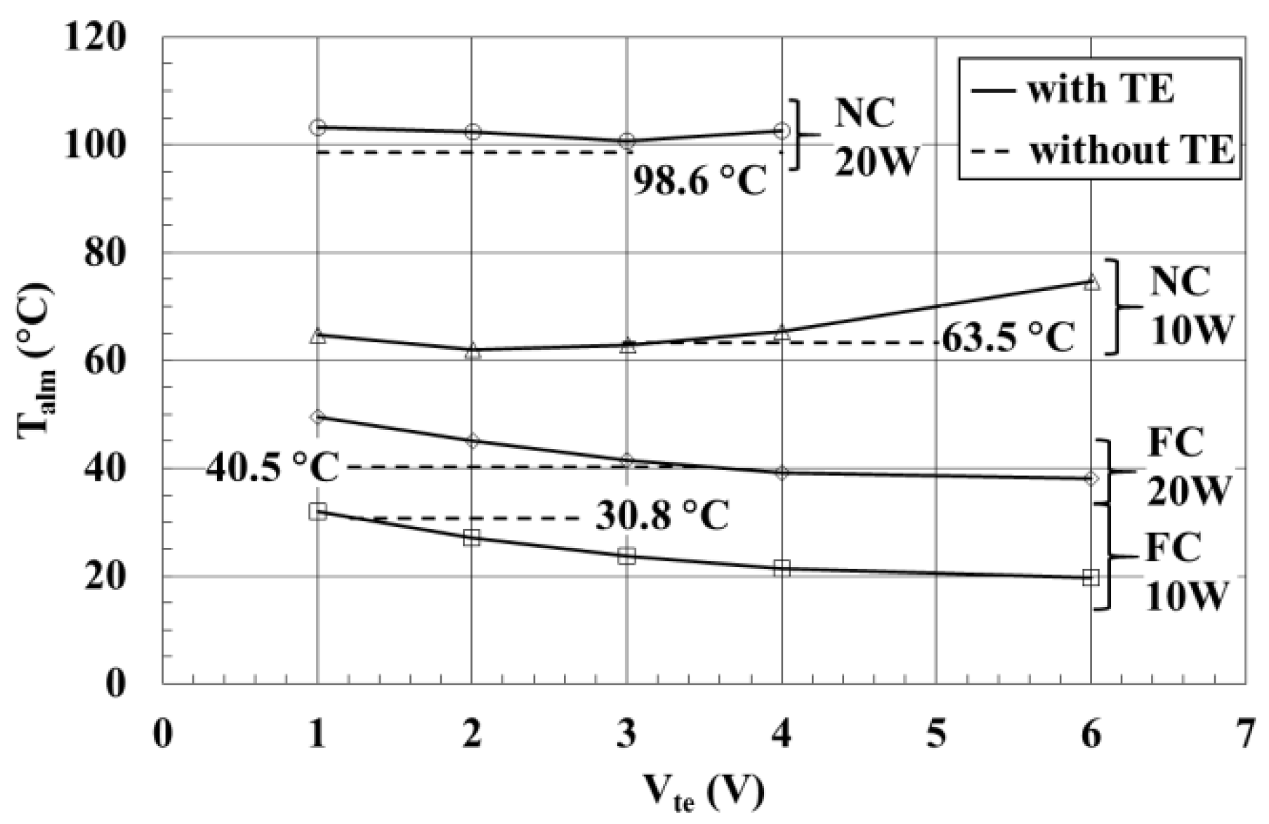
- The surface temperature of the aluminium block is higher under NC when compared to FC, as expected, because of less efficient cooling.
- Lower power input (PEH) results in lower temperature.
- Under the NC cooling mode, the temperature is lower without the use of the TE at both TE applied voltages (Vte) of 10 W and 20 W.
- In other words, the use of the TE module is not effective under the NC cooling mode. The heat transfer resistance of the TE module has a negative effect on the natural heat loss.
4. Conclusions
Acknowledgments
Author Contributions
Conflicts of Interest
References
- Lee, S.; Song, S.; Au, V.; Moran, K.P. Constriction/spreading resistance model for electeronic packaging. In Proceedings of the ASME/JSME Engineering Conference, New York, NY, USA, 19–24 March 1995.
- Simons, R.E. Simple formulas for estimating thermal spreading resistance. Electron. Cool. Mag. 2004, 10, 2. [Google Scholar]
- Hasan, A.; Hejase, H.; Abdelbaqi, S.; Assi, A.; Hamdan, M.O. Comparative effectiveness of different phase change materials to improve cooling performance of heat sinks for electronic devices. Appl. Sci. 2016, 6. [Google Scholar] [CrossRef]
- Ellison, G.N. Maximum thermal spreading resistance for rectangular sources and plates with nonunity aspect ratios. IEEE Trans. Compon. Packag. Technol. 2003, 26, 439–454. [Google Scholar] [CrossRef]
- Muzychka, Y.S.; Culham, J.R.; Yovanovich, M.M. Thermal spreading resistance of eccentric heat sources on rectangular flux channels. Trans. ASME 2003, 125, 178–185. [Google Scholar] [CrossRef]
- Rowe, D.M. General Principles and basic considerations. In Thermoelectrics Handbook–Macro to Nano; Taylor & Francis: Boca Raton, FL, USA, 2006. [Google Scholar]
- Riffat, S.B.; Ma, X. Improving the coefficient of performance of thermoelectric cooling systems: A review. Int. J. Energy Res. 2004, 28, 753–768. [Google Scholar] [CrossRef]
- Lee, H.S. Thermal Design Heat Sinks, Thermoelectrics, Heat Pipes, Compact Heat Exchangers, and Solar Cells; Wiley: Hoboken, NJ, USA, 2010. [Google Scholar]
- Sasaki, K.; Shindoh, T.; Itoh, Y. Enhancement of energy use efficiency by simultaneous of cooling and heating action during thermoelectric conversion. In Proceedings of the 22nd International Conference on Thermoelectrics, La Grande Motte, France, 17–21 August 2003; pp. 637–640.
- Uemura, K.I. Commercial Peltier Modules. In Handbook of Thermoelectrics; Rowe, D.M., Ed.; CRC Press: Boca Raton, FL, USA, 1995. [Google Scholar]
- Webb, R.L.; Gilley, M.D.; Zarnescu, V. Advanced heat exchange technology for thermoelectric cooling devices. Trans. ASME 1998, 120, 98–105. [Google Scholar] [CrossRef]
- Riffat, S.B.; Ma, X. Optimum selection (design) of thermoelectric modules for large capacity heat pump applications. Int. J. Energy Res. 2008, 28, 1231–1242. [Google Scholar] [CrossRef]
- Chein, R.; Huang, G. Thermoelectric cooler application in electronic cooling. Appl. Therm. Eng. 2004, 24, 2207–2217. [Google Scholar] [CrossRef]
- Kim, W.T.; Kim, K.S.; Lee, Y. Design of a two-phase loop thermosyphon for telecommunications system. KSME Int. J. 1998, 12, 942–955. [Google Scholar] [CrossRef]
- Huang, B.J.; Chin, C.J.; Duang, C.L. A design method of thermoelectric cooler. Int. J. Refrig. 2008, 23, 208–218. [Google Scholar] [CrossRef]
- Palacios, R.; Arenas, A.; Pecharroman, R.R.; Pagola, F.L. Analytical procedure to obtain internal parameters from performance curves of commercial thermoelectric modules. Appl. Therm. Eng. 2009, 29, 3501–3505. [Google Scholar] [CrossRef]
- Vian, J.G.; Astrain, D. Development of a heat exchanger for the cold side of a thermoelectric module. Appl. Therm. Eng. 2008, 28, 1514–1521. [Google Scholar] [CrossRef]


| NC/FC | Run # | PEH (W) | Vte (V) | Ite (A) | Pte (W) | Ta (°C) | Ts (°C) | Tc ≈ Talm (°C) | Th (°C) | ΔTte (°C) | Tm (°C) | COPc | Th,theory (°C) |
|---|---|---|---|---|---|---|---|---|---|---|---|---|---|
| NC | D1 | 10.1 | 1.01 | 0.52 | 0.52 | 20.6 | 65.7 | 64.7 | 64.8 | 0.1 | 64.8 | 19.34 | 63.8 |
| 10.0 | 2.00 | 0.85 | 1.69 | 20.3 | 62.9 | 61.9 | 69.2 | 7.2 | 65.5 | 5.89 | 68.8 | ||
| 10.0 | 3.00 | 1.16 | 3.50 | 20.3 | 63.8 | 62.8 | 77.1 | 14.3 | 69.9 | 2.86 | 76.6 | ||
| 10.0 | 4.01 | 1.47 | 5.88 | 20.2 | 66.3 | 65.3 | 85.9 | 20.6 | 75.6 | 1.70 | 85.9 | ||
| 10.0 | 6.00 | 2.02 | 12.13 | 20.0 | 75.7 | 74.6 | 106.9 | 32.3 | 90.7 | 0.82 | 107.5 | ||
| D2 | 19.9 | 1.00 | 0.61 | 0.61 | 20.9 | 105.4 | 103.2 | 96.0 | −7.2 | 99.6 | 32.57 | 93.6 | |
| 19.8 | 2.00 | 0.90 | 1.81 | 20.1 | 104.5 | 102.3 | 102.0 | −0.4 | 102.1 | 10.97 | 99.3 | ||
| 19.8 | 3.00 | 1.19 | 3.57 | 20.2 | 102.9 | 100.7 | 107.1 | 6.4 | 103.9 | 5.55 | 105.1 | ||
| 19.8 | 4.00 | 1.47 | 5.88 | 20.1 | 104.8 | 102.5 | 115.0 | 12.5 | 108.8 | 3.37 | 113.3 | ||
| - | 6.00 | - | - | - | - | - | - | - | - | - | - | ||
| FC | D3 | 10.3 | 1.00 | 0.63 | 0.63 | 19.9 | 32.9 | 31.9 | 30.8 | −1.1 | 31.4 | 16.36 | 30.6 |
| 10.0 | 2.00 | 1.04 | 2.08 | 20.3 | 28.2 | 27.1 | 33.0 | 5.9 | 30.0 | 4.80 | 33.2 | ||
| 9.9 | 3.00 | 1.45 | 4.36 | 20.5 | 24.8 | 23.8 | 36.1 | 12.3 | 30.0 | 2.28 | 36.5 | ||
| 10.0 | 4.00 | 1.84 | 7.37 | 20.7 | 23.3 | 21.3 | 39.6 | 18.3 | 30.4 | 1.36 | 40.0 | ||
| 10.0 | 6.00 | 2.62 | 15.7 | 20.7 | 20.7 | 19.6 | 48.8 | 29.2 | 34.2 | 0.63 | 48.9 | ||
| D4 | 20.1 | 1.00 | 0.80 | 0.80 | 20.1 | 51.7 | 49.5 | 40.5 | −9.0 | 45.0 | 25.00 | 39.3 | |
| 20.3 | 2.01 | 1.19 | 2.38 | 20.1 | 47.3 | 45.1 | 42.9 | −2.2 | 44.0 | 8.50 | 41.7 | ||
| 20.0 | 3.00 | 1.57 | 4.72 | 20.1 | 43.6 | 41.5 | 45.7 | 4.2 | 43.6 | 4.25 | 44.5 | ||
| 20.0 | 4.00 | 1.96 | 7.84 | 19.9 | 41.3 | 39.2 | 49.1 | 9.9 | 44.2 | 2.55 | 48.0 | ||
| 20.3 | 6.00 | 2.70 | 16.2 | 20.3 | 40.1 | 38.0 | 58.3 | 20.3 | 48.2 | 1.25 | 57.0 |
© 2017 by the authors. Licensee MDPI, Basel, Switzerland. This article is an open access article distributed under the terms and conditions of the Creative Commons Attribution (CC BY) license ( http://creativecommons.org/licenses/by/4.0/).
Share and Cite
Ong, K.S.; Tan, C.F.; Lai, K.C. Methodological Considerations of Using Thermoelectrics with Fin Heat Sinks for Cooling Applications. Appl. Sci. 2017, 7, 62. https://doi.org/10.3390/app7020062
Ong KS, Tan CF, Lai KC. Methodological Considerations of Using Thermoelectrics with Fin Heat Sinks for Cooling Applications. Applied Sciences. 2017; 7(2):62. https://doi.org/10.3390/app7020062
Chicago/Turabian StyleOng, Kok Seng, Choon Foong Tan, and Koon Chun Lai. 2017. "Methodological Considerations of Using Thermoelectrics with Fin Heat Sinks for Cooling Applications" Applied Sciences 7, no. 2: 62. https://doi.org/10.3390/app7020062
APA StyleOng, K. S., Tan, C. F., & Lai, K. C. (2017). Methodological Considerations of Using Thermoelectrics with Fin Heat Sinks for Cooling Applications. Applied Sciences, 7(2), 62. https://doi.org/10.3390/app7020062