Article

A New Maximum Power Point Estimator Control Strategy to Maximize Output Power of the Double Stator Permanent Magnet Generator

by
Norhisam Misron
1,2,*,
Chockalingam Aravind Vaithilingam
3,
Nashiren Farzilah Mailah
1,
Kudo Masaya
4 and
Tsuyoshi Hanamoto
4
1
Department of Electrical & Electronic Engineering, University Putra Malaysia, 43400 Serdang, Selangor, Malaysia
2
Institute of Advanced Technology (ITMA), Universiti Putra Malaysia, 43400 Serdang, Selangor, Malaysia
3
Computer Intelligence Applied Research Group (CIARG), School of Engineering, Taylor’s University, 47500 Petaling Jaya, Selangor, Malaysia
4
Department of Biological Functions and Engineering, Graduate School of Life Science and Systems Engineering, Kyushu Institute of Technology, Kyushu 804-8550, Japan
*
Author to whom correspondence should be addressed.
Appl. Sci. 2016, 6(8), 218; https://doi.org/10.3390/app6080218
Submission received: 22 February 2016 / Revised: 22 June 2016 / Accepted: 25 July 2016 / Published: 17 August 2016
(This article belongs to the Section Energy Science and Technology)

Abstract

:
A new control estimator to maximize the power generated with a maximum power point estimator is introduced. The power mapping characteristics from the double-stator generator are modeled as a mathematical equation which is used to develop the estimator for maximum power tracking to maximize the generated power. The proposed estimator automatically traces the instantaneous maximum power at various load conditions. However, to stabilize the output voltage, a boost converter is used from the inverter side. The developed double-stator generator is tested with the new estimator for the maximizing power generation capability under laboratory conditions. The experimental results confirm that with the new estimator, the average power generation capability is increased by 12% and the peak value is increase by 22%.

1. Introduction

Permanent magnet generators these days are manufactured in a wide range of sizes and for numerous applications. They have a wide range of applications including as auxiliary generators mounted on the engines in automobiles [1], motorcycles [2], tidal [3] and aircraft [4]. These types of generators are electronically commutated compared to wound field generators, making power control feasible. Also, the development of high-energy rare earth magnets and NdFeB magnets adds an advantage towards improvement in generating capability electro-magnetically [5]. New types of rotary [6,7,8] and linear machines [9,10] are feasible today due to advancements in permanent magnets and the advanced control strategy. However, the biggest challenge in power generation is that the electrical parameters are highly limited by load fluctuations. The use of a high-power generator such as the double-stator generator [11,12] and double rotor [13] machines increases the efficiency even for short-duration applications [14]. Double-stator machines as in Reference [11] with reduced weight to decrease the losses to a greater extent through the removal of heat caused by high density in the electric loadings. References [12,13,14] introduce the double rotor more typical for short-duration characteristics which shows better performances. Magnetic circuit design variations such as in References [14,15,16] are possible, but are developed without dynamic load considerations. The idea of the power line estimator for dynamic operation as used in solar tracking is the motivation of this research. There are other estimators in the literature such as those used in thermo-electric power generation [17], hybrid power generation systems [18,19], improved hybrid with fault studies [20,21,22], solar tracking [23], and wind operations [24,25]. This proposed estimator is slightly different, as the case where it depends on the load (dynamic) is formulated through a current equation that brings the best fit curve characteristics of the estimator.
In this work, the power characteristics of the double-stator generator developed [15] using the design procedure [16] together with the load condition are simulated to derive the line of trace (estimator). The values derived from the power mapping are modeled as a mathematical equation. The new estimator control strategy method we presented in this work demonstrates that the estimator used in the dynamic loading fluctuation is highly beneficial, particularly for systems with short-duration generation requirements [14]. The power generation using the double-stator generator, the mathematical formulation of the control strategy used in this approach, its experimental implementation and the result analysis are presented in the subsequent sections.

2. System on Power Generation using Double-Stator Generator

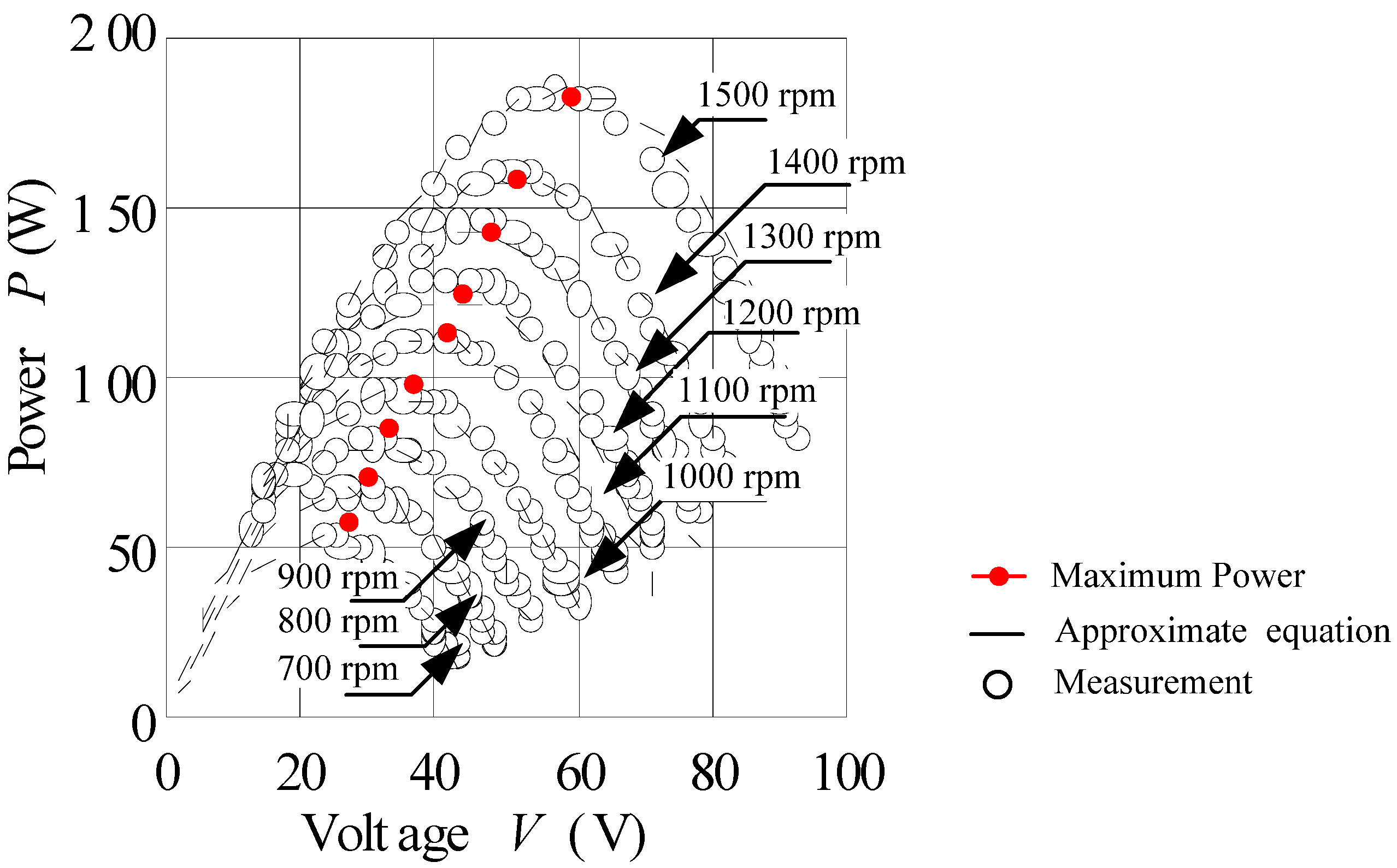
2.1. Power Mapping of Double-Stator Permanent Magnet Generator

The generator that used in this estimation is a high power density double-stator permanent magnet generator (DSPMG) [11]. The detailed design procedure of such a type of machine is presented in Reference [16]. Figure 1 shows the structure of the DSPMG and the generator is simulated in a finite element analysis tool for the power density characteristics. The maximum power is captured during modeling when the load reduced from the maximum (maximum impedance value) value and is plotted as the power mapping characteristics.
The performance of the double-stator generator uses the power mapping approach in which the spectra of the power and the voltage generated at various speeds are computed is as shown in Figure 2a,b. Figure 2a shows the power mapping for the generator. In order to get this power mapping, it is tested with various load conditions for speed variations. The output is coupled to the rectifier and capacitor for the generation of direct current (DC) voltage. The electronic load resistance is changed from 3 to 100 ohm and the generated output power is plotted. The maximum power generated is 180 W at the rotational speed of 1500 rpm with a load 10 ohm. The relation between the speed, the load and generated power is clearly understood through this power mapping data. Besides that, the relation between the voltage, current and output power in Figure 2b is calculated using Equations (1) and (2) and the efficiency characteristics are shown as in Figure 2c.
V = I × R
P = I × V

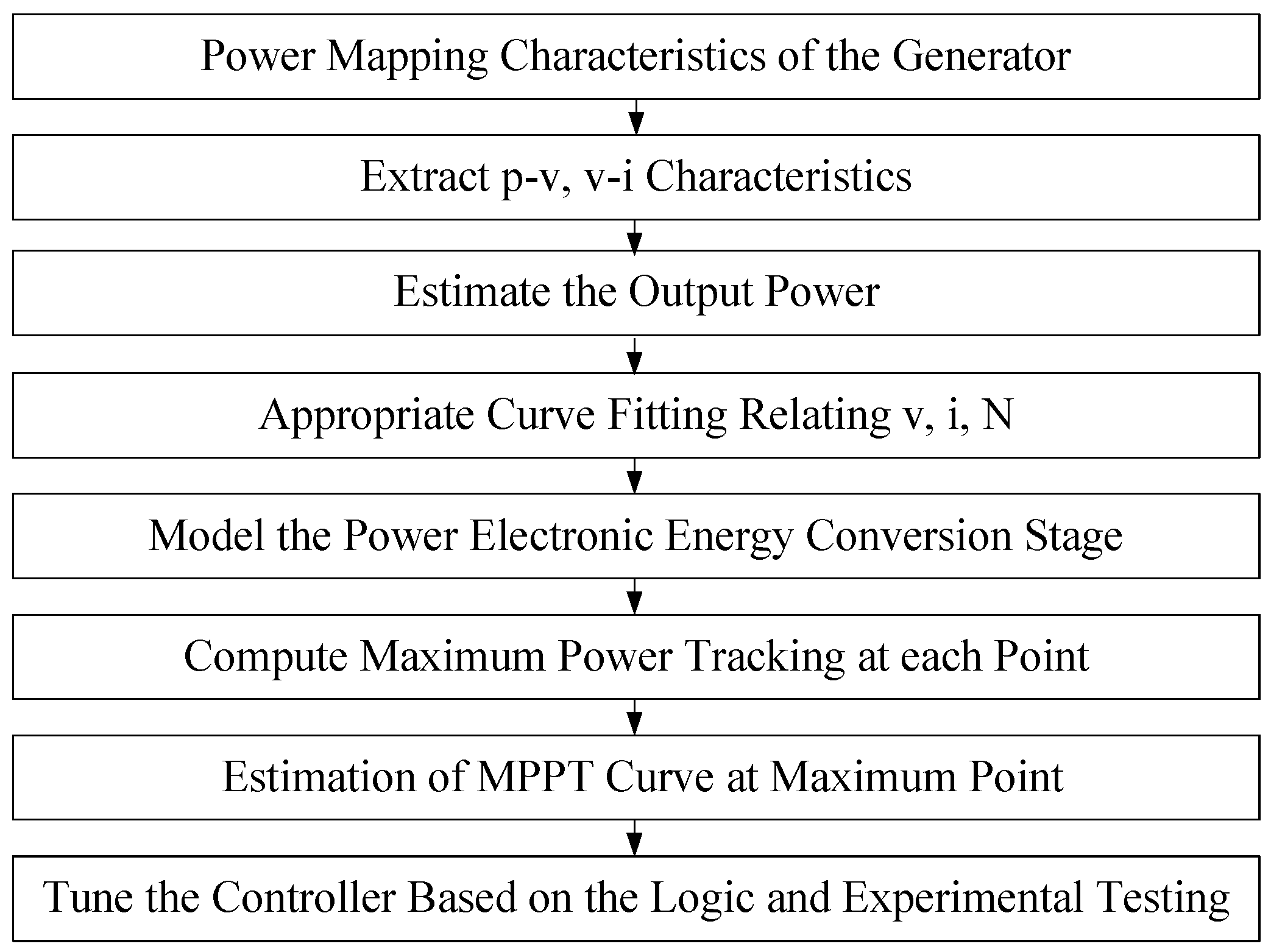
2.2. Extraction of the Best Curve Fit and the Methodology in Designing the Estimator for the Controller

Figure 3 shows the flowchart for the method used for the maximum power point tracker in order to maximize the power output. Using the MATLAB tool the generic current equation relating the voltage and speed is developed. From the power mapping characteristics the power-voltage (p, v) and power-current (p, i) are extracted. The double-stator generator is then modeled in an open circuit with the power electronic circuit with this extracted output. The designed power converter (boost converter) is modeled using the state-space averaging method and the plot for the various speeds to estimate the maximum power point is traced. Once the modeled system of power mapping with the electronic drive is tested in simulations, the data is then stored in the microcontroller unit and is tested.

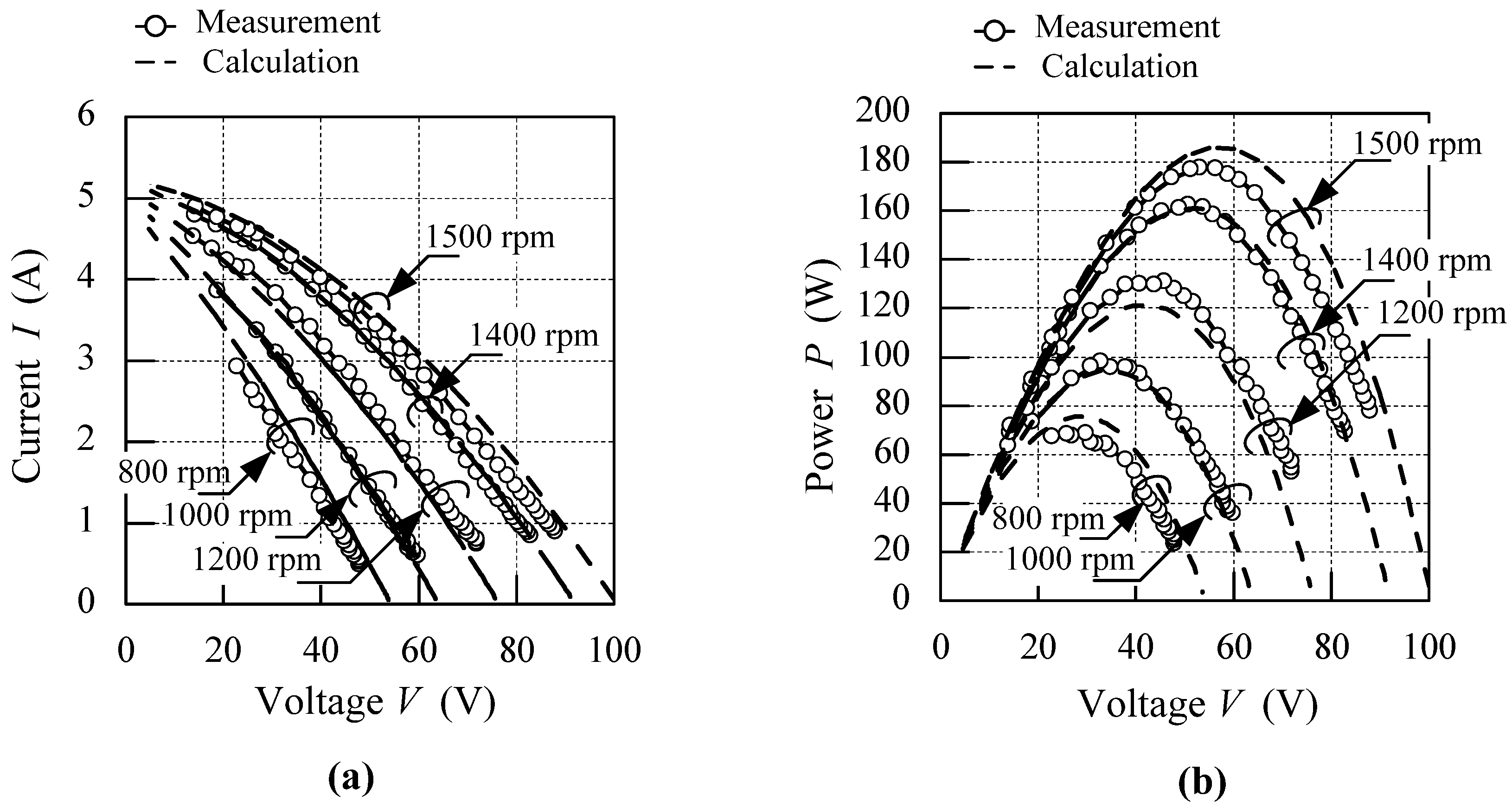
2.3. Conversion of Power Mapping to v-i (voltage-current), v-p (voltage-power) Characteristics

The generator characteristics from power mapping are converted to the voltage current v-i (voltage-current) characteristic and the voltage power v-p (voltage-power) characteristic in order to estimate the output power in the simulation environment. Figure 4a shows the schematic of the generator and Figure 4b shows the generator with the rectifier model. The fitting process from the power mapping characteristics is done through MATLAB and the relation between the voltage, current and speed is expressed as in Equation (3).
I = −4 × 10⁻⁴ × V2 + (−0.137 + (8.35 × 10⁻⁵ × N)) × V + 4.66 + 3.84 × 10⁻⁴ × N
where I is the current in (A), V is the voltage in (V) and N is the speed of the generator in (rpm).
Figure 5 shows the characteristics of v-i and v-p from the power mapping. Figure 5a shows the current variations compared to that of the load. The v-i characteristics in Figure 5b show the value for every speed condition. Initially, the power is increased with the increase in the voltage until the maximum value is reached, and then it starts reducing at a certain voltage. For instance, at the speed of 1500 rpm, the maximum output power is 180 W and the voltage is 55 V. At each instant the speed shows the difference between the maximum value and the optimal voltage value. The calculations of the current and voltage are also plotted in the same graph and the results agree with that of the measurement value. The maximum difference of 8% does not affect the simulation value for estimation.

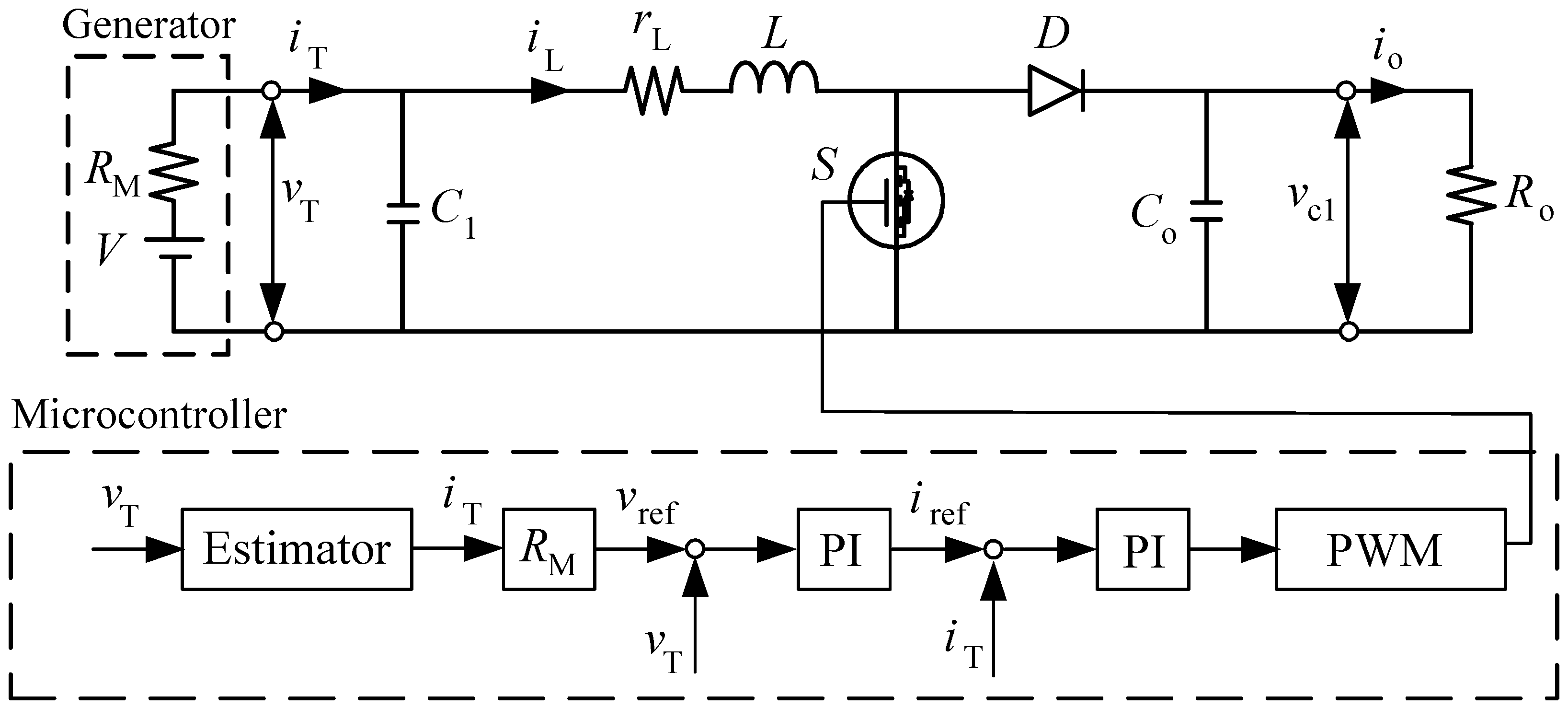
3. Maximum Power Point Estimator

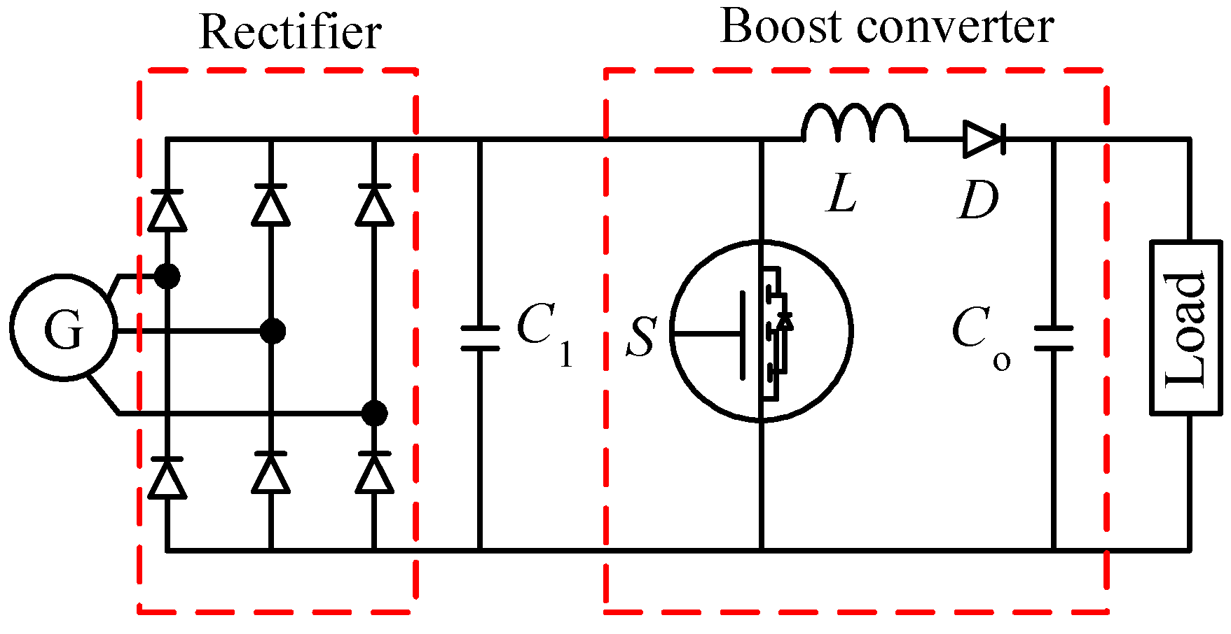
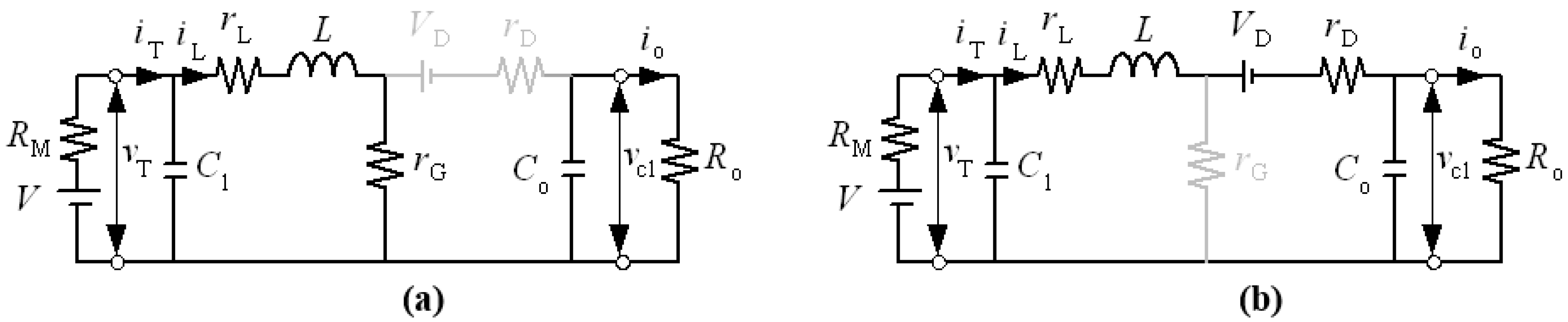
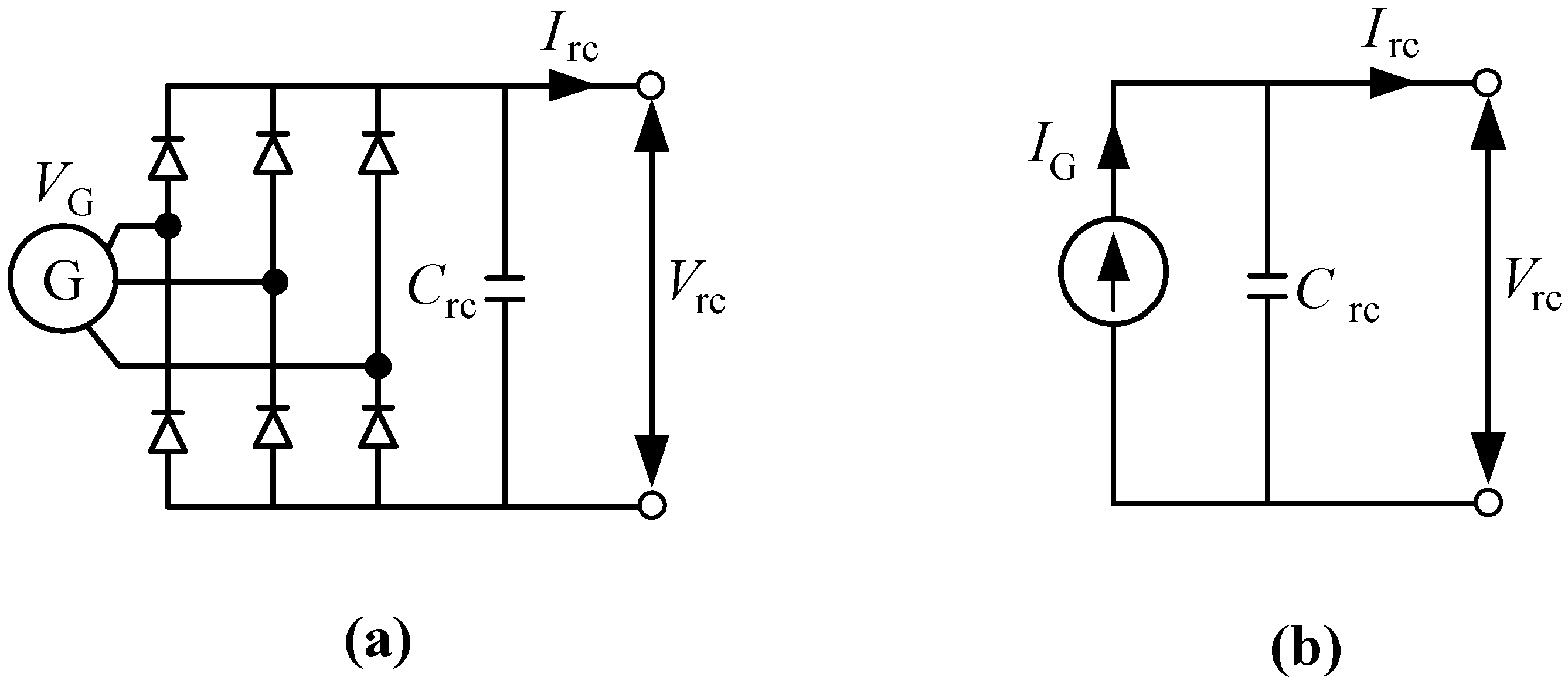
3.1. Modeling of Power Generation Unit

Figure 6 shows the designed circuit configuration that can deliver to both the DC load and alternating current (AC) load. With the DC load, the buck converter is used for generating DC voltage. For the AC load, the circuit consists of two sets of a boost converter and a single-phase inverter to generate the AC voltage. Boost converters are used to interleave the voltage stabilization on the circuit [26,27] and with hybrid controllers, as in Reference [28], they would help in increasing the operating performance of the plant. Table 1 shows the circuit component used in this design. The filter circuit includes in the DC side as the link DC capacitor (CRec ), the inductor (L1),the resistor (RDC) and the output capacitor (CA). Two boost inductors (L2, L3) and the corresponding capacitors (CB, CC) are usen in the boost design. The duty ratio of the switch for the first-stage boost converter in this research is limited to the maximum value of 0.75. If this duty ratio is high, the voltage vRec is reduced and the generated power is also reduced; hence, a two-stage boost converter is used. The second-stage boost converter is regulated at DC 400 V. The AC side filter design includes resistor (RAC) inductor (Lf) and capacitor (Cf). The output voltage vAC of the inverter is AC 240 Vrms. So, the modulation amplitude mAC is 0.849. Therefore, the reference voltage v A C * is given as in Equation (4).
v A C * = 0.849 sin ω t
Generally, DC/DC converters consist of an inductor, a capacitor, a diode, a switch element, and a resistor. When switch G of the DC/DC boost converter accepts ON/OFF signals, the output voltage increases. The timing of the ON/OFF signal is referred to as the duty cycle and as it increases, the load impedance Z is also changed depending on the individual parameters of each element. A suitable duty cycle to switch G is used to achieve impedance matching between the generator and load [29]. Figure 7 shows the DC/DC boost converter with the generator modelled as voltage source (V) with resistance (RM). During the ON condition the switch resistance (rG) is minimal since it is short circuited, a current (iL), flows through the coil represented with resistance of (rL) and inductance (L). The output voltage (vc1) is computed as the capacitor(C0) is supplying the current (i0) to the load resistance. During the OFF condition the switch resistance is maximum and hence the voltage source (VD) with internal resistance gets added to the source voltage making the boost in the output voltage.
The boost converter circuit operates in continuous conduction mode (CCM) by the ON/OFF switch G, and the circuit is analyzed linearly by applying the state-space averaging method. When the switch G is turned on, G is conducting and diode D is opened. The energy is accumulated from the double-stator generator to the reactor L and the load power is supplied from the smoothing capacitor C0. Based on the equivalent circuit, Equations (5)–(7) are derived by using Kirchhoff’s law.
C 1 d V T d t + i L = V M V T R M
L d i L d t + ( r L + r G ) i L = V T
C 0 d V o d t + V 0 R 0 = 0
The state-space equations for the above design variable are as in Equations (8)–(10).
x =   [ v T i L v 0 ] T
d x d t =   A 1 x + B 1 V M
A 1 = [ 1 R M C 1 1 C 1 0 1 L ( r L + r G ) L 0 0 0 1 R 0 C 0 ] B 1 = [ 1 R M C 1 0 0 ]
When the switch G is turned off, G is opened and diode D is conducting, and the energy is charged through the smoothing capacitor C 0 from the generator and the reactor L and it is channeled to the load R 0 . Based on the equivalent circuit, the following equations as in the above case, Equations (11)–(16), are derived by using Kirchhoff’s law.
C 1 d V T d t + i L = V M V T R M
L d i L d t + ( r L + r D ) i L = V T ( V D + V o )
C 0 d V o d t = V 0 R 0 + i L
Similarly to the case of the switch being on, the following formula is derived by organizing equations as in Equations (14)–(16).
u = [ V M V D ] T
d x ˙ d t = A 2 x + B 2 u
A 2 = [ 1 R M C 1 1 C 1 0 1 L ( r L + r D ) L 1 L 0 1 C o 1 R 0 C 1 ] B 2 = [ 1 R M C 1 0 0 0 1 L 0 ]
The average value of the state variable is defined as in Equation (17):
x ¯ = [ v T ¯ i L ¯ v 0 ¯ ] T
The duty cycle when the switch G is turn on is defined as D, and when the switch G is turn off it is defined as in Equation (18).
D × ( D + D = 1 )
The state-space averaging equation can be expressed as in the following Equations (19)–(21):
d x ˙ d t = A x ˙ + B u
where
A = D A 1 + D ˙ A 2 ; B = D B 1 + D ˙ B 2
Therefore,
A 1 = [ 1 R M C 1 1 C 1 0 1 L ( r L + D r G + D ˙ r G ) L D ˙ L 0 D ˙ C o 1 R 0 C 0 ] B 1 = [ 1 R M C 1 0 0 0 D ˙ L 0 ]
The steady-state value Χ =   [ V T I L V 0 ] T can be expressed as in the following equation by d x ( t ) ¯ d t = 0 .
x =   A 1 B u
Using the above, the Equation (23) matrix is derived:
[ V T I L V 0 ] = 1 r + R M [ r V M + D ˙ V D R M V M D ˙ V D D ˙ V M R o D 2 ˙ V D R o ]
where
r = r L + D r G + D r D + D ' 2 R o
The output voltage V T of the double-stator generator is given in Equation (25).
V T = r V M + D ˙ V D R M r L + D r G + D r D + D ' 2 R o + R M
The internal voltage V M of the double-stator generator is given by Equation (26).
V M = ( r + R M ) V T D ˙ V D R M r L + D r G + D r D + D ' 2 R o
The average value I L can be expressed as in Equation (27).
I L = V M D ˙ V D r L + D r G + D r D + D ' 2 R o + R M
Therefore, V M and reactor current I L is estimated as the output voltage V T of the double-stator generator which is measured through experimental design. The average value of the reactor current I L is defined as equal to I T by the smoothing effect of the capacitor C 1 . To substitute the value of the terminal voltage, V T to the estimation equation, I L ^ is estimated.
I L = V M V T R M

3.2. Evaluation of the Estimator Characteristics for the Double-Stator Generator

Figure 8 shows the characteristics of the double-stator generator for each rotation speed. If the rotation speed increases, the generating power also increases. This characteristic indicates that there are maximum power points for each rotation speed of the generator. When the internal resistance RM equals the load impedance Z, the condition is such where the power for each rotation speed is at maximum. From the measurement data the approximate equation at each speed is plotted. From the plot at each speed the maximum power point is traced as a power line for the controller to be tuned.

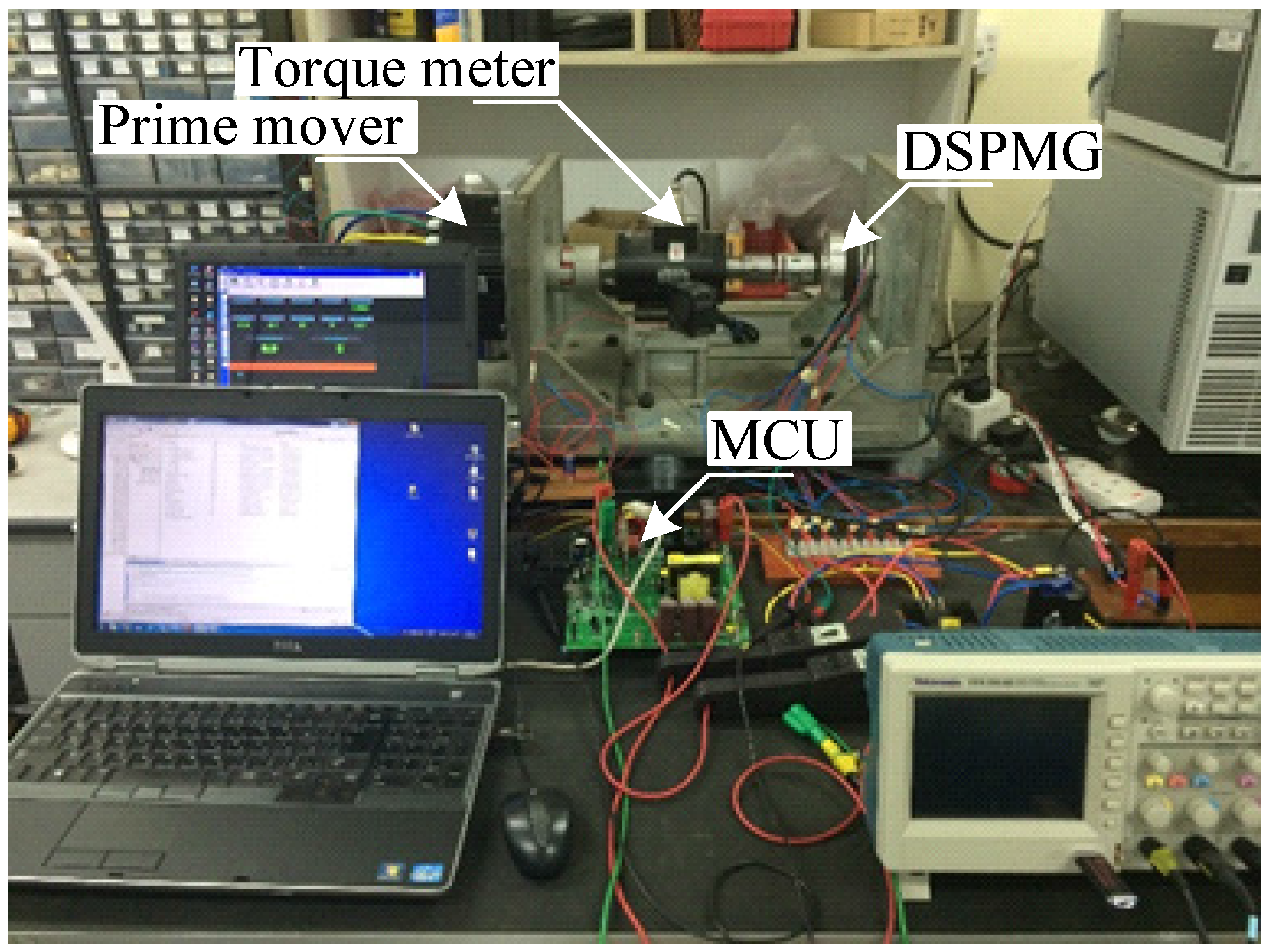
4. Experimental Evaluation of the New Estimator

Figure 9 shows the interface driving unit of the new estimator generation unit with the DC/DC converters enclosing an inductor, a capacitor, a diode, a switch element, and a resistor. When the internal resistance RM equals the load impedance Z, the condition is called impedance matching [30], where the power for each rotation speed is at maximum. The condition of impedance matching is defined as R M I T = V T . The estimator control is used to control the command value V R e f .
V R e f =   R M I T ^ = R M I L ^
The system consists of a double-stator generator, a DC/DC boost converter, an MCU (microcontroller unit), and a load resistance R 0 , as shown in Figure 10. Primarily the MCU measures the input voltage VT from the voltage sensor. Secondly, it estimates the inductor current I L and the inductive voltage VM, using VT. Finally, the MCU calculates a suitable duty cycle D for the maximum power with each rotational speed and load resistance. This series of events is called the maximum power point estimator control strategy. During the experimental testing of the estimator, the generator is started, and the value of the load resistance is decreased from 100 to 5 Ω to perform the estimator control. Then, the rotation speed is varied from 700 to 1500 rpm to repeat the experimentation further.
Figure 11 shows the experimental result of the comparison with and without the estimator. The black line indicates the maximum power points for each rotation speed of the generator by analytical computations. The red line indicates the result of using the experimental estimator control method. The experimental results are in close agreement to that of the ideal maximum power point result with the estimator curve developed for maximum power output. Therefore, the results confirm that the new control strategy is suitable for a generator with dynamic load changes.

5. Conclusions

The new control strategy to maximize the generated power through the maximum power point estimator is developed and discussed. Initially, the power mapping characteristics with the load circuit and the power electronic circuit is modeled to develop the estimator. The estimator curve evolved out of this design is used as an estimator by the controller in order to maximize the power generation. The modeled estimator is tested with the laboratory system using the generator and the electronic drive controller with dynamic loads. It is observed through the experimental design that the controller tracks the maximum power point as the load is fluctuated. This helps the generator to maximize the power generated. The experimental results confirm that with the new estimator control strategy, the average power generation capability is increased by 12% and the peak value is increased by 22%. The developed strategy can be implemented with other generator systems; however, the tuning needs to be done based on the application.

Acknowledgments

The authors would like to acknowledge the support of University Putra Malaysia for providing space for the experimental setup.

Author Contributions

Norhisam Misron conceived and designed the experiments, Kudo Masaya and Tsuyoshi Hanamoto performed the experiments; Norhisam Misron and Chockalingam Aravind Vaithilingam analyzed the data; Nashiren Farzilah Mailah contributed for the analysis tools; Norhisam Misron and Chockalingam Aravind Vaithilingam wrote the paper.

Conflicts of Interest

The authors declare no conflict of interest.

References

  1. Hill, C.I.; Zanchetta, P.; Bozhko, S.V. Accelerated Electromechanical Modeling of a Distributed Internal Combustion Engine Generator Unit. Energies 2012, 5, 2232–2247. [Google Scholar] [CrossRef]
  2. Wang, M.-H.; Huang, M.-L.; Jiang, W.-J. Maximum Power Point Tracking and Harmonic Reducing Control Method for Generator-Based Exercise Equipment. Energies 2016, 9, 103. [Google Scholar] [CrossRef]
  3. Zhang, J.; Moreau, L.; Machmoum, M. Optimal control strategies of a double stator permanent magnet generator applied in tidal current energy extracting. In Proceedings of the Symposium De Génie Électrique (SGE’14): EF-EPF-MGE 2014, Cachan, France, 8–9 July 2014.
  4. Dubensky, A.A.; Kovalev, K.L.; Larionoff, A.E.; Modestov, K.A.; Penkin, V.T.; Poltavets, V.N. An Outlook of the Use of Cryogenic Electric Machines Onboard Aircraft. IEEE Appl. Trans. Supercond. 2016, 26, 1–4. [Google Scholar] [CrossRef]
  5. Chen, L.; Hopkinson, D.; Wang, J.; Cockburn, A.; Sparkes, M.; O’Neill, W. Reduced Dysprosium Permanent Magnets and Their Applications in Electric Vehicle Traction Motors. IEEE Trans. Magn. 2015, 51, 1–4. [Google Scholar]
  6. Norhisam, M.; Nazifah, A.; Aris, I.; Wakiwaka, H.; Nirei, M. Effect of magnet size on torque characteristic of three phase permanent magnet brushless DC motor. In Proceedings of the 2010 IEEE Student Conference on Research and Development—Engineering: Innovation and Beyond (SCOReD), Putrajaya, Malaysia, 13–14 December 2010; pp. 293–296.
  7. Aravind, C.V.; Norhisam, M.; Aris, I.; Marhaban, M.H.; Ahmad, D.; Nirei, M. Double-Rotor Switched Reluctance Machine (DRSRM): Fundamentals and magnetic circuit analysis. In Proceedings of the 2011 IEEE Student Conference on Research and Development (SCOReD), Cyberjaya, Malaysia, 19–20 December 2011; pp. 294–299.
  8. Norhisam, M.; Alias, K.; Firdaus, R.N.; Mahmod, S.; Mariun, N.; Razak, J.A. Comparison on thrust characteristic of linear oscillatory actuators. In Proceedings of the IEEE International Power and Energy Conference, Putra Jaya, Malaysia, 28–29 November 2006; pp. 470–475.
  9. Norhisam, M.; Wong, K.C.; Mariun, N.; Wakiwaka, H. Double side interior permanent magnet linear synchronous motor and drive system. In Proceedings of the International Conference on Power Electronics and Drive Systems, Honolulu, HI, USA, 12–15 December 2005; pp. 1370–1373.
  10. Yu, C.; Niu, S.; Ho, S.L.; Fu, W.N. Design and Analysis of a Magnetless Double-Rotor Flux Switching Motor for Low Cost Application. IEEE Trans. Magn. 2014, 50, 1–4. [Google Scholar] [CrossRef]
  11. Djebarri, S.; Charpentier, J.F.; Scuiller, F.; Benbouzid, M. Design and Performance Analysis of Double Stator Axial Flux PM Generator for Rim Driven Marine Current Turbines. IEEE J. Ocean. Eng. 2016, 41, 50–66. [Google Scholar] [Green Version]
  12. Vaithilingam, C.A.; Misron, N.; Zare, M.R.; Aris, I.; Marhaban, M.H. Computation of Electromagnetic Torque in a Double Rotor Switched Reluctance Motor Using Flux Tube Methods. Energies 2012, 5, 4008–4026. [Google Scholar] [CrossRef]
  13. Nordin, N.I.A.A.; Ariffin, H.; Andou, Y.; Hassan, M.A.; Shirai, Y.; Nishida, H.; Yunus, W.M.Z.W.; Karuppuchamy, S.; Ibrahim, N.A. Modification of Oil Palm Mesocarp Fiber Characteristics Using Superheated Steam Treatment. Molecules 2013, 18, 9132–9146. [Google Scholar] [CrossRef] [PubMed]
  14. Aravind, C.V.; Norhisam, M.; Suresh, K.M.; Ramesh, G.P. Assessment on the Harnessing of the Energy from the Back Pressure Chamber of Palm Oil Mill. J. Sci. Technol. 2015, 10, 46–56. [Google Scholar]
  15. Misron, N.B.; Rizuan, S.; Firdaus, R.N.; Vaithilingam, C.A.; Wakiwaka, H.; Nirei, M. Comparative evaluation on power-speed density of portable permanent magnet generators for agricultural application. Prog. Electromagn. Res. 2012, 129, 345–363. [Google Scholar]
  16. Aravind, C.V.; Grace, I.; Rozita, T.; Rajparthiban, R.; Rajprasad, R.; Wong, Y.V. Universal computer aided design for electrical machines. In Proceedings of the 2012 IEEE 8th International Colloquium on Signal Processing and Its Applications (CSPA), Melaka, Malaysia, 23–25 March 2012; pp. 99–104.
  17. Ou, T.C.; Hong, C.M. Dynamic operation and control of microgrid hybrid power systems. Energy 2014, 66, 1314–1323. [Google Scholar] [CrossRef]
  18. Yamada, H.; Kimura, K.; Hanamoto, T. A Novel MPPT Control Method of Thermoelectric Power Generation with Single Sensor. Appl. Sci. 2013, 3, 545–558. [Google Scholar] [CrossRef]
  19. Hong, C.M.; Ou, T.C.; Lu, K.H. Development of intelligent MPPT (maximum power point tracking) control for a grid-connected hybrid power generation system. Energy 2013, 50, 270–279. [Google Scholar] [CrossRef]
  20. Ou, T.C.; Chuang, S.J.; Hong, C.M.; Wu, R.C.; Tsao, T.P.; Chen, C.Y. Self-regulation Ground Faults Model for Microgrid Distribution. ICIC Express Lett. Part B Appl. 2015, 6, 3225–3230. [Google Scholar]
  21. Ou, T.C. A novel unsymmetrical faults analysis for microgrid distribution systems. Int. J. Electr. Power Energy Syst. 2012, 43, 1017–1024. [Google Scholar] [CrossRef]
  22. Ou, T.C. Ground fault current analysis with a direct building algorithm for microgrid distribution. Int. J. Electr. Power Energy Syst. 2013, 53, 867–875. [Google Scholar] [CrossRef]
  23. Chen, J.-H.; Yau, H.-T.; Lu, J.-H. Implementation of FPGA-Based Charge Control for a Self-Sufficient Solar Tracking Power Supply System. Appl. Sci. 2016, 6, 41. [Google Scholar] [CrossRef]
  24. Valencia, P.A.O.; Ramos-Paja, C.A. Sliding-Mode Controller for Maximum Power Point Tracking in Grid-Connected Photovoltaic Systems. Energies 2015, 8, 12363–12387. [Google Scholar] [CrossRef]
  25. Phan, D.-C.; Yamamoto, S. Maximum Energy Output of a DFIG Wind Turbine Using an Improved MPPT-Curve Method. Energies 2015, 8, 11718–11736. [Google Scholar] [CrossRef]
  26. Zhu, Y.; Cheng, M.; Hua, W.; Wang, W. A Novel Maximum Power Point Tracking Control for Permanent Magnet Direct Drive Wind Energy Conversion Systems. Energies 2012, 5, 1398–1412. [Google Scholar] [CrossRef]
  27. Arango, E.; Ramos-Paja, C.A.; Calvente, J.; Giral, R.; Serna, S. Asymmetrical Interleaved DC/DC Switching Converters for Photovoltaic and Fuel Cell Applications—Part 1: Circuit Generation, Analysis and Design. Energies 2012, 5, 4590–4623. [Google Scholar] [CrossRef]
  28. Lin, W.M.; Hong, C.M.; Ou, C.; Chiu, T.M. Hybrid Intelligent Control of PMSG wind Generation System Using Pitch Angle Control with RBFN. Energy Convers. Manag. 2011, 52, 1244–1251. [Google Scholar] [CrossRef]
  29. Tseng, S.-Y.; Wang, H.-Y. A Photovoltaic Power System Using a High Step-up Converter for DC Load Applications. Energies 2013, 6, 1068–1100. [Google Scholar] [CrossRef]
  30. Duong, T.P.; Lee, J.-W. A Dynamically Adaptable Impedance-Matching System for Midrange Wireless Power Transfer with Misalignment. Energies 2015, 8, 7593–7617. [Google Scholar] [CrossRef]
Figure 1. Structural configuration of the double-stator permanent magnet generator.
Applsci 06 00218 g001
Figure 2. Power mapping characteristics and efficiency characteristics. (a) Power mapping of load–speed characteristic; (b) Power mapping of voltage–speed characteristic; (c) Efficiency of double-stator permanent magnet generator.
Applsci 06 00218 g002
Figure 3. Flowchart of the method used for the estimator. p-v: power-voltage; v-i: voltage-current; N: speed; MPPT: maximum power point tracker.
Applsci 06 00218 g003
Figure 4. Simplified double-stator generator and rectifier model. (a) Model of the double-stator generator with a rectifier; (b) Simulation mode. Irc: load current; Vrc: load voltage; Crc: load capacitance; VG: generator voltage; IG: generator current.
Applsci 06 00218 g004
Figure 5. Relationship between voltage, current and power: (a) v-i characteristics; (b) v-p characteristics.
Applsci 06 00218 g005
Figure 6. Configuration on modeling of power generation system. C1: Linking capacitor; C0: Output capacitor; L: Inductance; D: Diode; G: Generator; S: power device switch.
Applsci 06 00218 g006
Figure 7. Circuit diagram in switch ON/OFF.
Applsci 06 00218 g007
Figure 8. Characteristics of the double-stator generator for each rotation speed.
Applsci 06 00218 g008
Figure 9. Configuration of the system using a DC/DC boost converter. RM: machine resistance; PI: proportional-integral; PWM: pulse width modulation.
Applsci 06 00218 g009
Figure 10. Experimental system with the new estimator control method. MCU: microcontroller unit; DSPMG: double-stator permanent magnet generator.
Applsci 06 00218 g010
Figure 11. With and without the new estimator control strategy.
Applsci 06 00218 g011
Table 1. Circuit component specifications. DC: direct current; AC: alternating current.
ItemSymbolUnitValue
DC capacitorCRec(μF)4700
DC filter inductorL1(mH)1
DC output capacitorCA(μF)470
DC resistorRDC(Ω)30
Boost inductorL2, L3(mH)1
DC capacitorCB(μF)10
DC capacitorCC(μF)1000
AC filter inductorLf(mH)1
AC filter capacitorCf(μF)10
AC resistorRAC(Ω)384

