Article

Biomedical Applications of Antibacterial Nanofiber Mats Made of Electrospinning with Wire Electrodes

1
Department of Materials and Textiles, Oriental Institute of Technology, New Taipei City 22061, Taiwan
2
Laboratory of Fiber Application and Manufacturing, Department of Fiber and Composite Materials, Feng Chia University, Taichung City 40724, Taiwan
3
School of Chinese Medicine, China Medical University, Taichung City 40402, Taiwan
4
Department of Fashion Design, Asia University, Taichung City 41354, Taiwan
*
Author to whom correspondence should be addressed.
Appl. Sci. 2016, 6(2), 46; https://doi.org/10.3390/app6020046
Submission received: 12 December 2015 / Revised: 22 January 2016 / Accepted: 28 January 2016 / Published: 4 February 2016
(This article belongs to the Section Nanotechnology and Applied Nanosciences)

Abstract

:
Twisted stainless steel wires are used as wire electrodes for electrospinning the polyvinyl alcohol (PVA)/zinc citrate nanofiber mats. The morphology and diameter of the nanofibers in PVA/zinc citrate nanofiber mats are evaluated. We measured the antibacterial efficacy against Staphylococcus aureus (S. aureus) and Escherichia coli (E. coli) of the nanofiber mats. We also examined the cell adhesion affinity of mammalian tissue culture cells on these nanofiber mats. Our results indicate that an increase in zinc citrate increases the viscosity and electrical conductivity of PVA solution. In addition, increasing zinc citrate results in a smaller diameter of nanofibers that reaches below 100 nm. According to the antibacterial test results, increasing zinc citrate enlarges the inhibition zone of S. aureus but only has a bacteriostatic effect against E. coli. Finally, cell adhesion test results indicate that all nanofiber mats have satisfactory cell attachment regardless of the content of zinc citrate.

Graphical Abstract

1. Introduction

Conventional single-needle electrospinning has been commonly studied as it is an easy method for manufacturing nanofibers [1]. Nanofibers that are produced by using electrospinning have diameter and morphology that depend on many factors, including the dissolution, dispersion, viscosity, and surface tension of polymers, the volatility and electrical conductivity of the solvents, electrospinning voltage, collection distance, and ambient temperature and humidity [2,3,4,5,6,7]. However, single-needle electrospinning has a production yield of 0.01–0.1 g/hr, which falls behind the requirement of mass production. In recent years, needleless electrospinning has been developed, and has a higher spinning efficiency than multi-needle electrospinning [8,9,10,11,12]. Needleless electrospinning does not clog and thus has potential for a greater yield [13,14,15,16,17,18,19,20,21,22,23,24,25,26,27,28].
Nanofibers are defined as fibers that have a diameter of less than 100 nm. They have a high porosity and a high specific surface, and are thus commonly used in many applications, including wound dressings [29,30], release control [31], tissue engineering scaffolds [32], filtrations in environmental applications [33], metal ion adsorption [34], battery separator [35], and bio-sensors [36]. In particular, the application of wound dressings involves a complicated process of wound healing where the cell extracellular matrix components and growth factors interact. The open wounds surface is often infected with microbes, including bacteria, funguses, and viruses. An infection of a wound is initiated by the adherences of bacteria to the surface of wounds, antibiotics, antimicrobial agents, and metallic particles are incorporated with the dressings. Therefore, antibacterial agents, such as chitosan [37], silver nanoparticles [38], or zinc oxide (ZnO) [39], have been added to electrospun nanofibers, thus increasing their potential in biomedical engineering applications.
There has been little research on the application of needleless electrospinning, and this study thus combines zinc citrate and polyvinyl alcohol (PVA) in order to form a PVA mixture for electrospinning nanofibers. This manufacturing method confirms the feasibility of the combination of other materials and needleless electrospinning technique, and also produces antibacterial nanofiber mats in a great volume. Stainless steel wires are twisted and serve as the wire electrodes for the production of PVA/zinc citrate nanofiber mats. The properties of polymer solutions, and morphology and diameter size of the nanofibers are examined, after which the antibacterial properties, cell attachment, and MTT (3-[4,5-dimethylthiazol-2-yl]-2,5-diphenyltetrazolium bromide) assay of nanofibers are studied.

2. Experimental Section
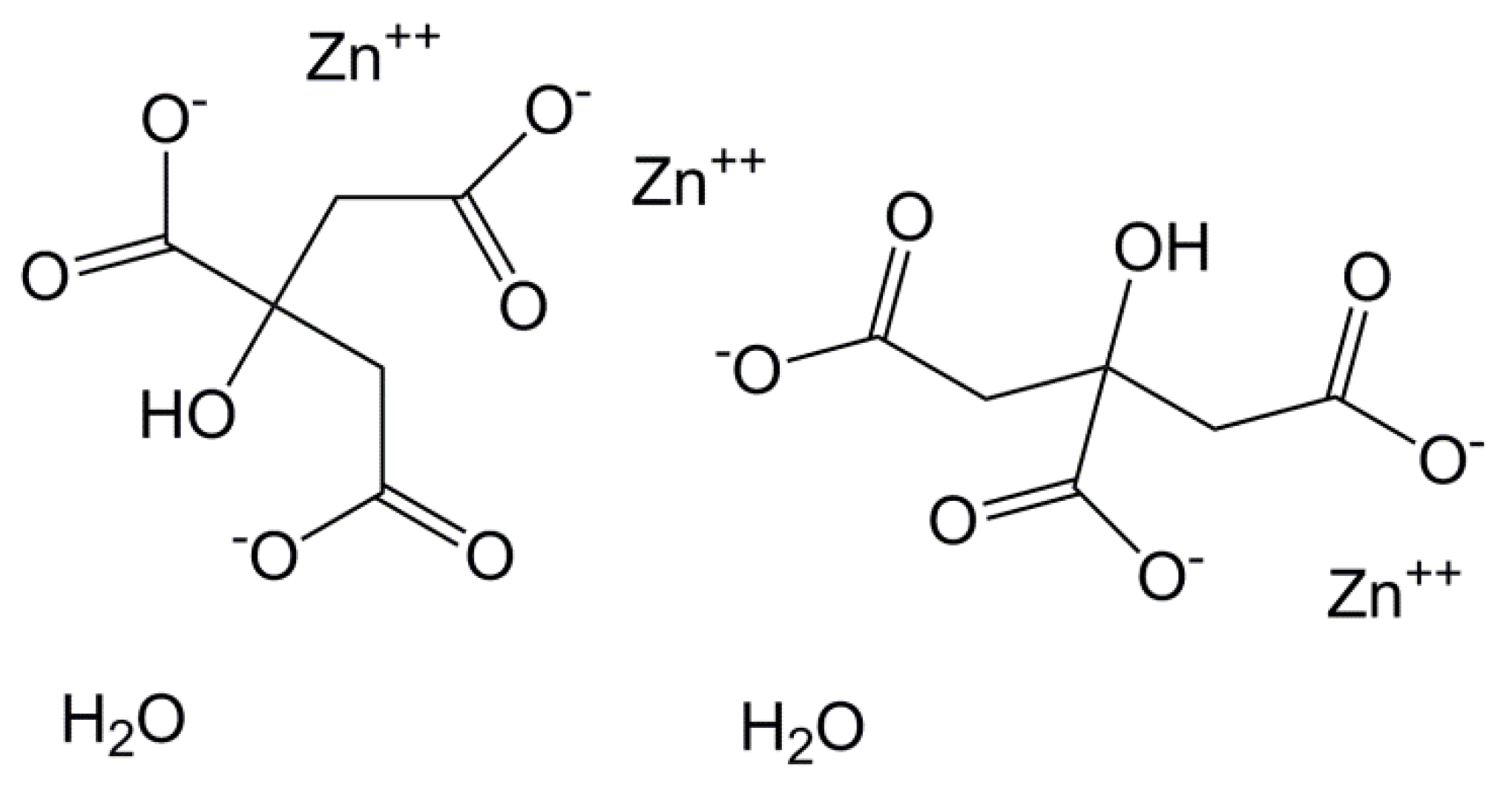
2.1. Materials

We used polyvinyl alcohol (PVA, Sigma-Aldrich, Ltd, Saint Louis, MO, USA) with a molecule weight of 89,000–98,000 kDa and 99% hydrolyzed. Stainless steel (SS) wires (King Metal Fiber Technology Co., Ltd., Taipei, Taiwan) have a diameter of 0.2 mm. Zinc citrate (Nihon Shiyaku Industries Ltd., Kyoto, Japan) has a Mw of 574.37. Phosphate-buffered saline (PBS) solution is purchased from Difco Laboritories Inc. (Detroit, MI, USA).

2.2. Methods

2.2.1. Solution Preparation

PVA powder is dissolved in deionized water in order to formulate 10 wt % PVA solution. The PVA solution is heated and blended on a magnetic stirrer at 90 °C for 12 h, followed by being added with 0.5, 1, 3, or 5 wt % zinc citrate and blended for another 12 h.

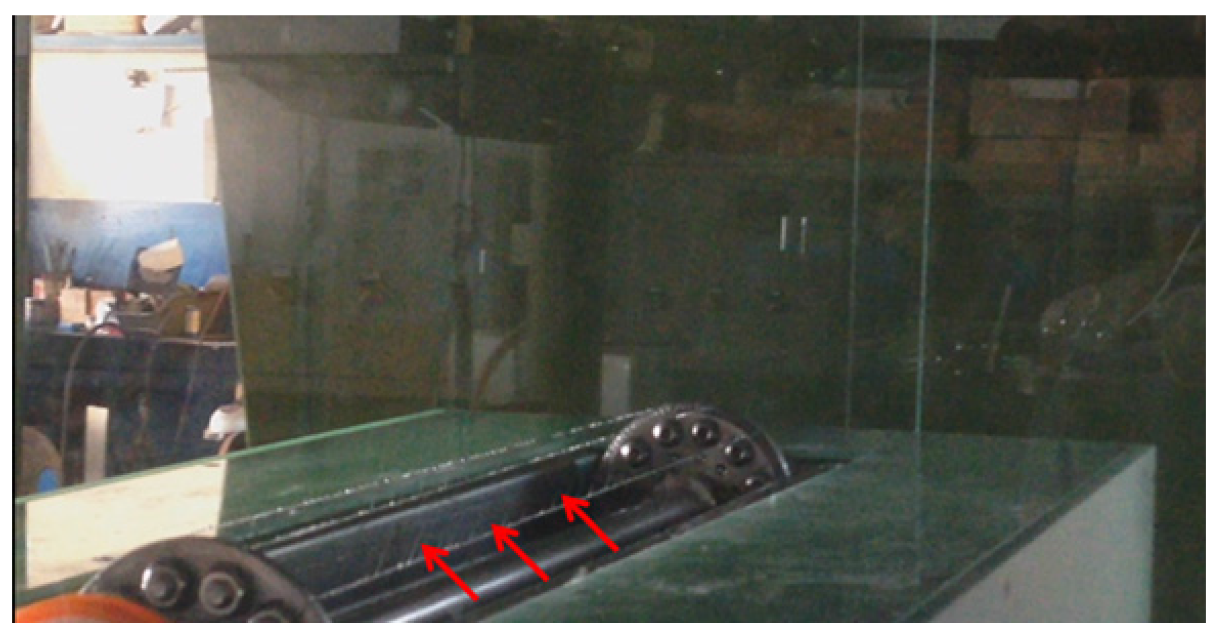
2.2.2. Electrospinning

In this study, stainless steel wires are twisted in order to form wire electrodes, as indicated in Figure 1a. The mechanism of needleless electrospinning used indicated in Figure 1b consists of mechanism elements as follows. The solution bath is mounted on the solution bath base. The motor releases the power transmission, while the belt revolves and activates the round bar where the positive pole of the high voltages is applied. Above the mechanism is a collector that the negative poles are connected with it. The electrospinning is introduced as follows. The wire electrode is affixed to the two ends of the disc, after which the spinneret is located in the bearing and are affixed to two ends of the bearing block. A dynamic force is powered by the motor, and thereby revolves the gears of the belt as well as their linking spinneret. The mixtures of PVA and different amounts of zinc citrate are poured into the solution bath. Next, the stainless steel wire electrode is rotated, and the polymer solution that is adhered to the wire electrode then forms spheres due to the surface tension, gravity, and viscosity. The spheres are then converted into Taylor cones as a result of the connection to a high voltage, followed by being converted into jets that are collected to the collector and complete the electrospinning process. The electrospinning voltage is 80 kV, the collection distance is 10 cm, and the rotation speed of the spinneret is 8 rpm. As indicated in Figure 2, there are numerous jets being extended and then formed into nanofibers via the wire electrode.
Figure 1. The mechanism of needleless electrospinning. (a) the image of a wire electrode and (b) the schematic drawing of electrospinning frame.
Applsci 06 00046 g001
Figure 2. Image of electrospinning that administers a wire electrode.
Applsci 06 00046 g002

2.3. Tests

2.3.1. Viscosity

A rotational viscometer (Fungilab, Barcelona, Spain) is used to measure the viscosity of the PVA solution and PVA/zinc citrate mixtures in order to examine the influences of different zinc citrate concentrations on the viscosity of mixtures, as well as the morphology of the electrospun nanofibers.

2.3.2. Conductivity

The electrical conductivity of the PVA solution and PVA/zinc citrate solutions are examined by using a pH/Conductivity Meter (EC500, Extech Instruments, Nashua, NH, USA.).

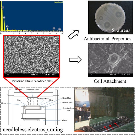
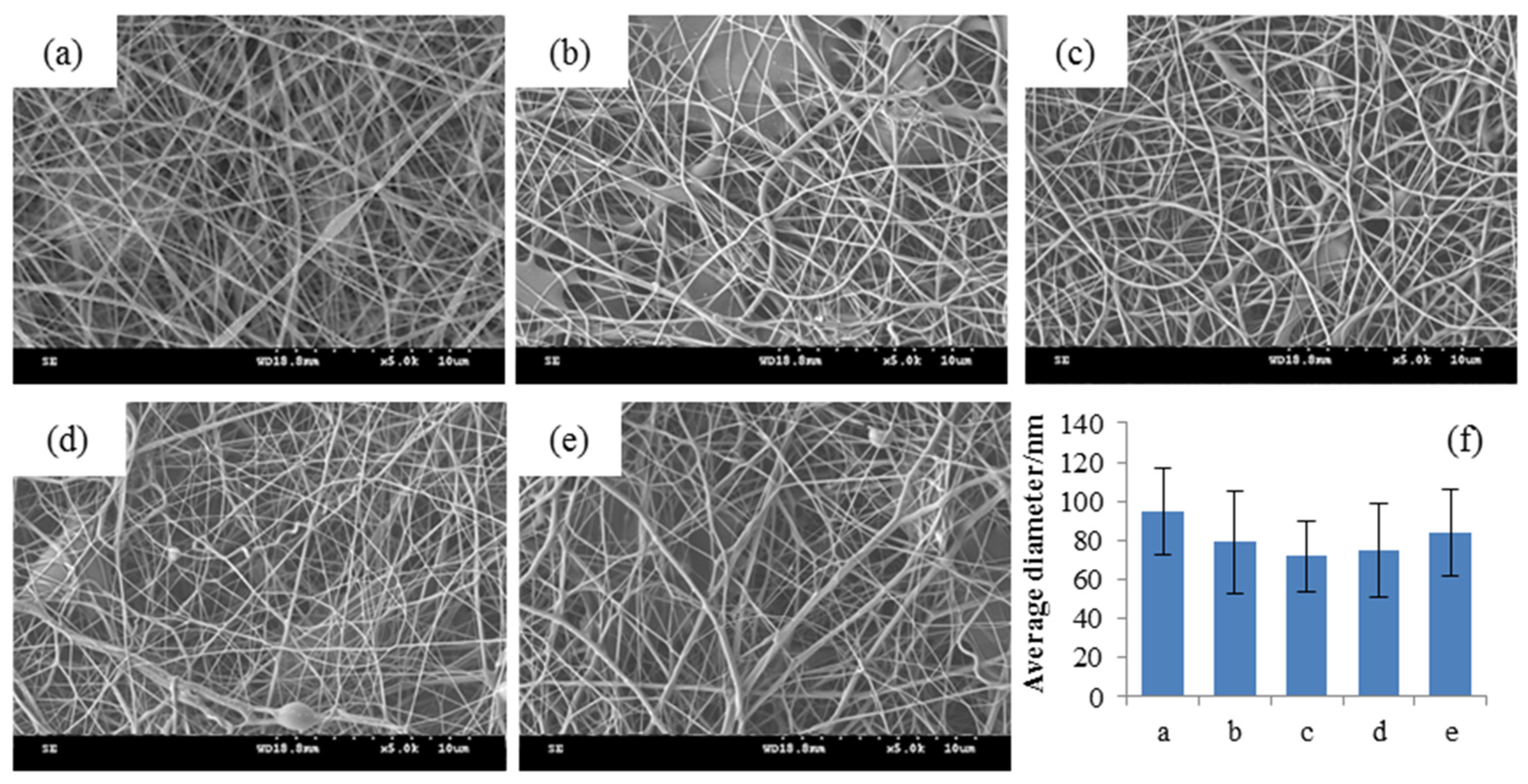
2.3.3. Scanning Electron Microscopey (SEM)

Electrospun nanofiber mats are dried in an oven at 40 °C for 24 h in order to remove the moisture from the surface of fibers. Afterwards, they are coated with a thin layer of gold for thirty seconds, after which a Field-Emission Scanning Electron Microscope (FE-SEM, JEOL USA, Inc., Peabody, MA, USA) is used with an operating voltage of 10 kV in order to observe the surface of the samples. Finally, an elemental analysis is conducted with incorporating an energy dispersive spectrum (EDS) to examine the morphology of the samples.

2.3.4. Diameter Analyses

The SEM images that record the morphology are analyzed with an Image-Pro 6.2 illustration (Media Cybernetics, Inc., Rockville, MD, USA). 100 pieces of nanofibers are used to measure their diameters and represent all of the nanofibers. This analysis clarifies the influences of the difference in electrospinning parameters on the diameter of nanofibers.

2.3.5. Antibacterial Test

Disc Diffusion Assay

A disc diffusion method is administered for the antibacterial activity analysis of electrospun nanofiber mats. S. aureus (ATCC 25923) and E. coli (ATCC25922) are used in this test, and they have constant colony forming units (CFUs) of 1.5 × 10⁵ determined by optical densities (OD). In addition, 0.1 mL bacteria suspension is smeared over an agar plate, after which the electrospun nanofiber mats are adhered to the agar. The plates are then placed in an incubator to culture for 18–24 h. After the plates are removed, the inhibition zones are measured.

Broth Dilution Assay

Staphylococcus aureus (S. aureus, ATCC 25923) and Escherichia coli (E. coli, ATCC25922) are used in this study. Their constant colony forming unit (CFUs) is 1.5 × 10⁵ according to the optical densities (OD). The bacteria liquid of 1 mL is placed in an incubator at 37 °C for twenty four hours. The bacteria liquid is then removed, and its optical density (OD) is measured with a Ultraviolet-visible spectrometer (Thermo Fisher Scientific Inc., Waltham, MA, USA) at a wavelength of 600 nm.

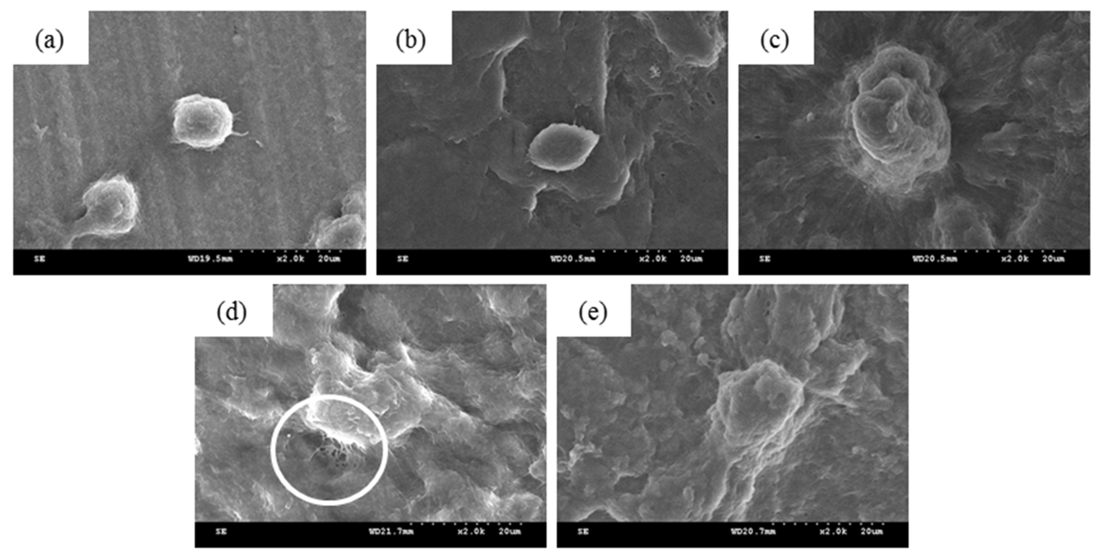
2.3.6. Cell Attachment
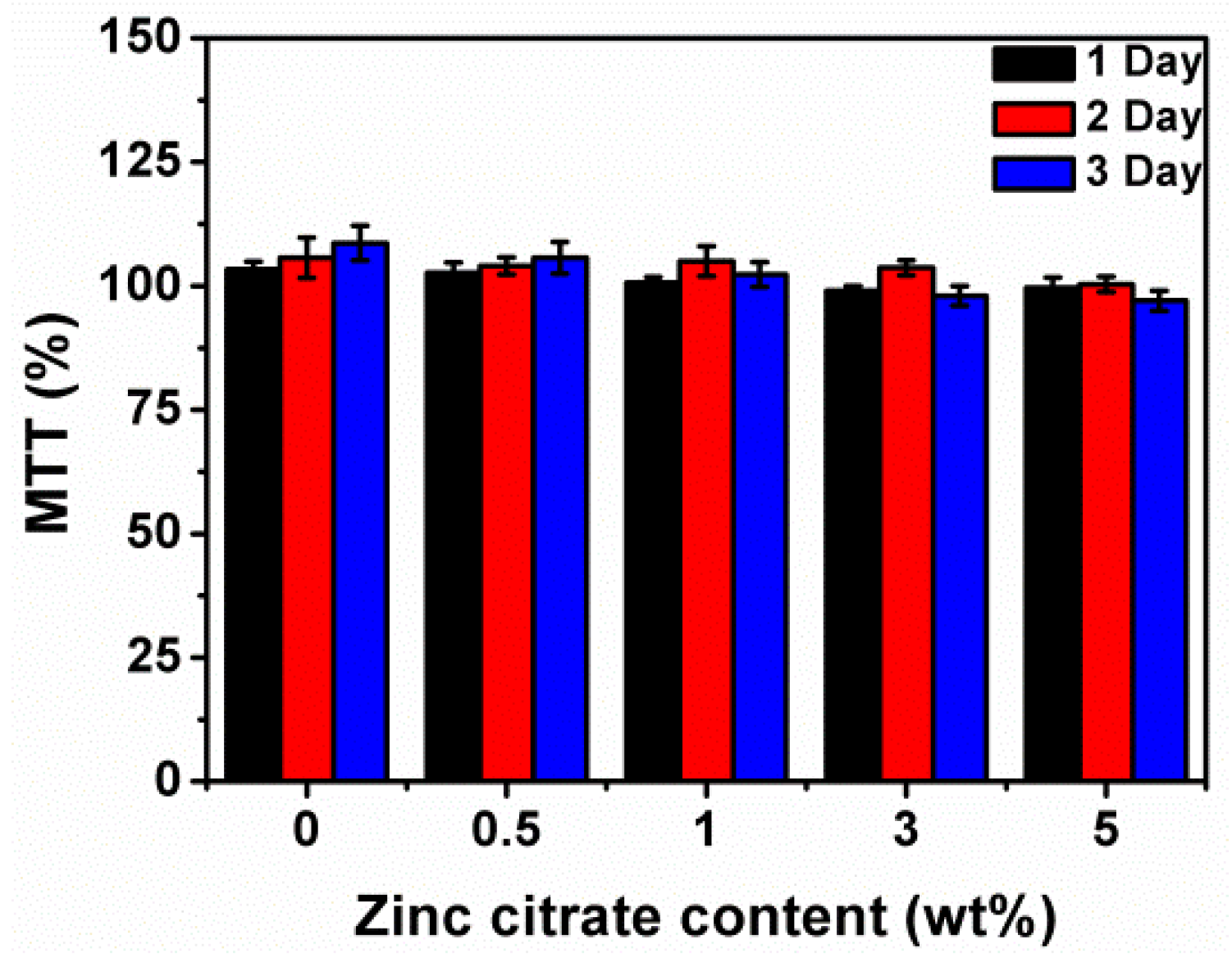
The sterilized samples are placed in a two-well dish. The cultured L929 mouse fibroblasts cells are diluted to have a cell density of 2 × 10⁴ cells/mL, after which a 1mL cell suspension and a 1 mL medium are infused into the each well. All of the materials are incubated in an incubator for 24 h. The nanofiber mat is then removed and rinsed with a PBS solution that is in a horizontal shaking bath. A 2.5% glutaraldehyde solution is added with a micropipette in order to immobilize cells for 24 h. Different concentrations of ethanol is also added with a micropipette to the 24-well to gradient drying the samples, after which the cell attachment and growth are observed with an SEM.

2.3.7. MTT Assay

The sterilized samples are examined in terms of cellular viability (%) via using an MTT (3-[4,5-dimethylthiazol-2-yl]-2,5-diphenyltetrazolium bromide assay. The sample extract at 10 μL with a concentration of 1.6 mg/L c.c. and MG-63 osteoblast cells at 90 μL with a concentration 104 cell/well are respectively infused into a 96-well culture plate. The culture plate is placed in an incubator at 37 °C, 5% CO2 for 24 h, 48 h and 72 h, after which the late is removed and then placed on a horizontal laminar flow table. A Pasteur pipette is used to suck the Minimum essential medium (MEM) from the plate. Afterwards, a mixture containing 70 μL MTT agent and culture medium with a volume ratio of 1:39 is added to each well of the plate. The plate is then kept in the dark for four hours, and then the MTT/medium mixture is removed. Dimethyl sulfoxide (DMSO) solvent at 70 μL is added to each well. An ELISA reader is used to measure the absorbance of the residual in the dish at the wavelength of 570 nm, and optical density (OD) is used to compute the cellular viability (%).
Cellular   viability   ( % ) = M e d i u m   c o n t a i n i n g   t h e   e x t r a c t   s o l u t i o n   o p t i c a l   d e n s i t i e s O p t i c a l   d e n s i t i e s   o f   t h e   f r e s h   m e d i u m × 10 %

3. Results and Discussion

3.1. Properties of PVA/Zinc Citrate Mixtures

Viscosity of electrospinning solution is an important index for electrospinning, and thus it is an important parameter for both conventional single-needle electrospinning and needleless electrospinning. When the viscosity of electrospinning solution falls in an optimal range, it has a significant influence on the morphology of fibers [40]. The viscosity of PVA solution increases from 489.9 mPa s to 992.3 mPa s as a result of an increase in zinc citrate, as indicated in Table 1. Zinc citrate is slightly water soluble, and thus its particles are dispersed in a PVA solution shown in Figure 3. Increasing the concentration of zinc citrate causes the reaction between zinc citrate and molecular chains, and thereby results in chain entanglements. As a result, viscosity of solution is proportional to the amount of zinc citrate.
Table 1. Viscosity of polyvinyl alcohol (PVA)/zinc citrate mixtures and specification of nanofiber mats.
Physical PropertiesZinc Citrate Content (wt%)
0 wt %0.5 wt %1 wt %3 wt %5 wt %
Viscosity (mPa s)489.9708920.4942.4992.3
conductivity (μS/m)0.57 × 1030.62 × 1030.70 × 1030.98 × 1031.28 × 103
Average diameter (nm)95 ± 2279 ± 2672 ± 1875 ± 2484 ± 22
Figure 3. The dispersion of zinc citrate in PVA/zinc citrate mixtures that contain (a) 0.5 wt %; (b) 1 wt %; (c) 3 wt %; and (d) 5 wt % zinc citrate. The mixtures are kept at room temperature a fortnight.
Applsci 06 00046 g003
Table 1 indicates that the PVA/zinc citrate mixture that contains 5 wt % zinc citrate has a higher electrical conductivity of 1.28 × 10³ μS/m, compared to the control group (0.57 × 10³ μS/m). Zinc citrate is an ionic compound that has electric charges. The zinc ions are released after zinc citrate is slightly dissolved in water, as indicated in Figure 4, which effectively strengthens the electrical conductivity of the mixtures. As indicated in the study by Jayakumar, the addition of metal compounds causes the electrical conductivity to increase [39].
Figure 4. Dissociation mechanism that zinc citrate releases electric charges after it is dissolved in water.
Applsci 06 00046 g004

3.2. Effects of Amount of Zinc Citrate on Morphology and Fiber Diameter of PVA/Zinc Citrate Nanofiber Mats

The morphology and diameter distribution of PVA/Zinc citrate nanofiber mats are indicated in Figure 5. The pure PVA nanofibers have a smooth morphology, and there are no beads or spindle apparatus observed in Figure 5a. The PVA/zinc citrate nanofiber mats are formed differently with the corresponding amount of zinc citrate as follows: spindle (0.5 wt %), small beads (1 wt %), beads and droplets (3 wt %), and beads and flat fibers (5 wt %), as indicated in Figure 5b–e. Such results are ascribed to the viscosity of the polymer solution. The viscosity of the polymer solution is proportional to the amount of zinc citrate, as indicated in Table 1, and thus a high viscosity is disadvantageous for electrospinning.
Figure 5. SEM images (5000×) of PVA/zinc citrate nanofiber mats containing (a) 0 wt %; (b) 0.5 wt %; (c) 1 wt %; (d) 3 wt %; and (e) 5 wt % zinc citrate; (f) is the diameter distribution of the nanofibers with the corresponding content of zinc citrate.
Applsci 06 00046 g005
In addition, SEM images also indicate that a high amount of zinc citrate increases the viscosity of PVA/zinc citrate mixtures, which prevents the solvent to volatilize for the fiber formation. Thus, there are some ill-formed fibers observed in the SEM images. In addition, Figure 5b–e indicates that the nanofibers have a distinct beaded-structure when the mixtures contain a greater amount of zinc citrate. This result is because zinc citrate particles and PVA are electrospun into nanofibers, and the particles are then attached to the surface of PVA nanofibers.
Moreover, SEM images indicate that the incorporation of zinc citrate provides nanofibers with a smaller diameter, which is in conformity with the results in Figure 5f. Figure 5f indicates the diameter distribution of PVA nanofibers where a, b, c, d, and e refer to different amounts of zinc citrate (i.e., 0, 0.5, 1, 3, and 5 wt %). The diameter of pure PVA nanofibers is 95 ± 22 nm, and the diameter of PVA/zinc citrate nanofibers have a diameter with the corresponding zinc citrate as follows: 79 ± 26 nm (0.5 wt %), 72 ± 18 nm (1 wt %), 75 ± 24 nm (3 wt %), and 84 ± 22 nm (5 wt %). After zinc citrate is dissolved in water, it can release zinc ions with a greater amount of electric charges. This provides the electrospinning jet with more electric charges in order to overcome the surface tension of the jet. The dissociation mechanism has now been provided in Figure 4. The electrical conductivity of electrospinning solution is thus proportional to the amount of zinc citrate, and the diameter decreases as a result of a high stretching force. The higher the electrical conductivity of electrospinning solution, the smaller the diameter of the nanofibers [41].

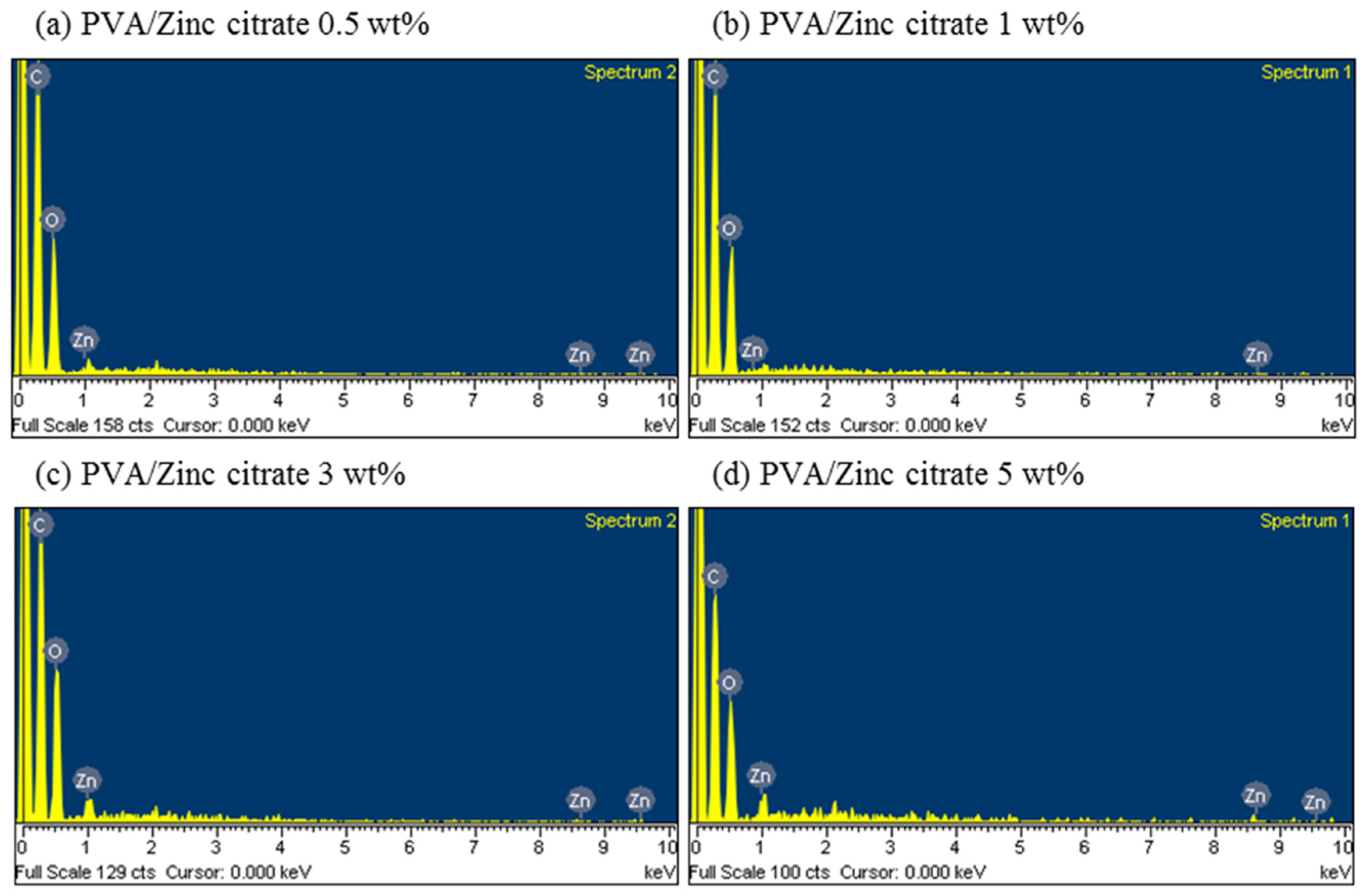
3.3. Element Analyses of PVA/Zinc Citrate Nanofiber Mats

Figure 6 indicates EDS analyses of PVA/zinc citrate nanofiber mats as related to various amounts of zinc citrate. EDS spectra demonstrates the presence of zinc. The content of zinc with their corresponding amount of zinc citrate are 0.74 wt % (0.5 wt %), 1.56 wt % (1 wt %), 3.18 wt % (3 wt %), and 4.69 wt % (5 wt %) as indicated in Table 2. The content of zinc measured by EDS has similar ratio to the amount of zinc citrate, which can be surmised that the nanofiber mats are evenly coated with a zinc element.
Figure 6. EDS charts of PVA/zinc citrate nanofiber mats that contain (a) 0 wt %; (b) 0.5 wt %; (c) 1 wt %; (d) 3 wt %; and (e) 5 wt % zinc citrate.
Applsci 06 00046 g006
Table 2. Element content of PVA/zinc citrate nanofiber mats as related to various amounts of zinc citrate.
ElementZinc Citrate Content (wt%)
0.5 wt %1 wt %3 wt %5 wt %
C K56.23%55.52%53.85%52.74%
O K43.02%42.93%42.97%42.57%
Zn L0.74%1.56%3.18%4.69%
Totals100

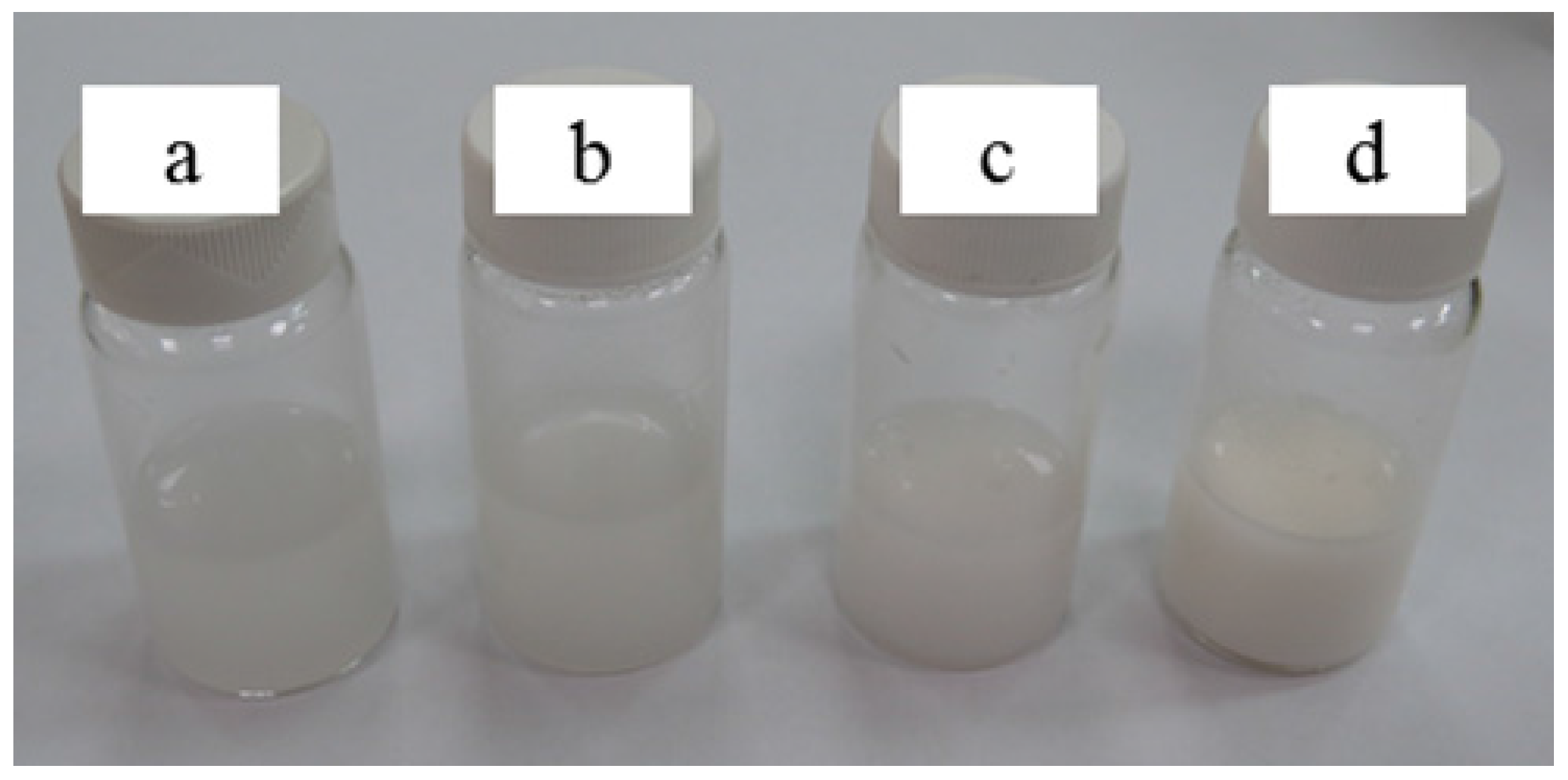
3.4. Effects of Amount of Zinc Citrate on Antibacterial Efficacy of PVA/Zinc Citrate Nanofiber Mats
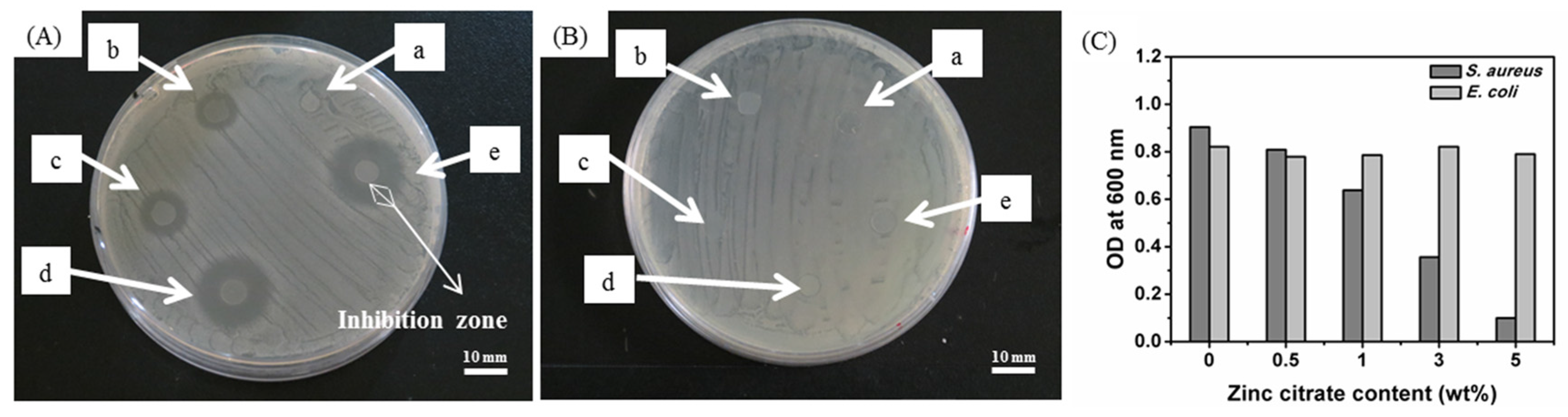
Antibacterial efficacy against S. aureus of PVA/zinc citrate nanofiber mats is indicated in Figure 7A. The pure PVA nanofiber mats are not bacteriostatic. In contrast, the addition of different amounts of zinc citrate (0.5, 1, 3, or 5 wt %) results in significant inhibition zones against S. aureus, and the diameter of the inhibition zone that PVA/zinc citrate nanofiber mats created is proportional to the amount of zinc citrate, as indicated in Table 3. The diameter of the inhibition zone of PVA/Zinc citrate nanofiber mats with the corresponding amount of zinc citrate are 5 mm (0.5 wt %), 7 mm (1 wt %), 11.8 mm (3 wt %), and 13.5 mm (5 wt %). In comparison to the inhibition zone caused by 0.5 wt % zinc citrate, the inhibition zone is increased by 1.4 times (1 wt %), 2.36 times (3 wt %), and 2.7 times (5 wt %). Adding 0.5 wt % zinc citrate has a significant antibacterial efficacy, and adding 5 wt % zinc citrate yields the maximum inhibition zone of 13.5 mm, which has only a slight 1.7 mm increase, in comparison to the inhibition zone caused by 3 wt % zinc citrate. This mild increase in the diameter of inhibition zone also suggests that 3 wt % zinc citrate is the optimal parameter.
Figure 7. The antibacterial efficacy of PVA/zinc citrate nanofiber mats against (A) S. aureus; (B) E. coli and (C) optical density. The mats are composed of (a) 0 wt %, (b) 0.5 wt %, (c) 1 wt %, (d) 3 wt %, and (e) 5 wt % zinc citrate.
Applsci 06 00046 g007
Table 3. The antibacterial efficacy of PVA/zinc citrate nanofiber mats against S. aureus.
SampleConcentration of Zinc Citrate (wt %)Electrospinning VoltageSize of Inhibition Zone (mm)
a (control)080 kV0
b0.580 kV5.0 ± 1.1
c180 kV7.0 ± 0.8
d380 kV11.8 ± 0.5
e580 kV13.5 ± 1.0
Zinc ions have antibacterial properties due to their positive charges, which interact with the negative charges of the cell wall of bacteria. The imbalance between positive and negative charges in turn causes damages to cell walls. The bacteria thus fail to regenerate their cell walls and then stop their proliferation. Yamamoto et al. indicate that zinc compound has antibacterial efficacy against S. aureus [42]. The antibacterial efficacy against E. coli is indicated in Figure 7B. Regardless of the amount of zinc citrate, the PVA/zinc citrate nanofiber mats do not cause any inhibition zones, and E. coli is absent over the PVA/zinc citrate nanofiber mats. This phenomenon indicates that PVA/zinc citrate nanofiber mats have only bacteriostatic, rather than antibacterial efficacy. Figure 7C indicates that a high content of zinc citrate causes a lower optical density of the suspension, which is composed of PVA/zinc citrate nanofiber mats and S. aureus solution, which exemplifies that the nanofiber mats possess a satisfactory antibacterial effect against S. aureus. In contrast, the optical density remains constant when PVA/zinc citrate nanofiber mat is cultured with E. coli is administered, indicating a mere bacteriostatic effect. These results are in conformity with Figure 7A,B.

3.5. Effects of Electrospinning Voltages on Morphology and Diameter of PVA/Zinc Citrate Nanofiber Mats
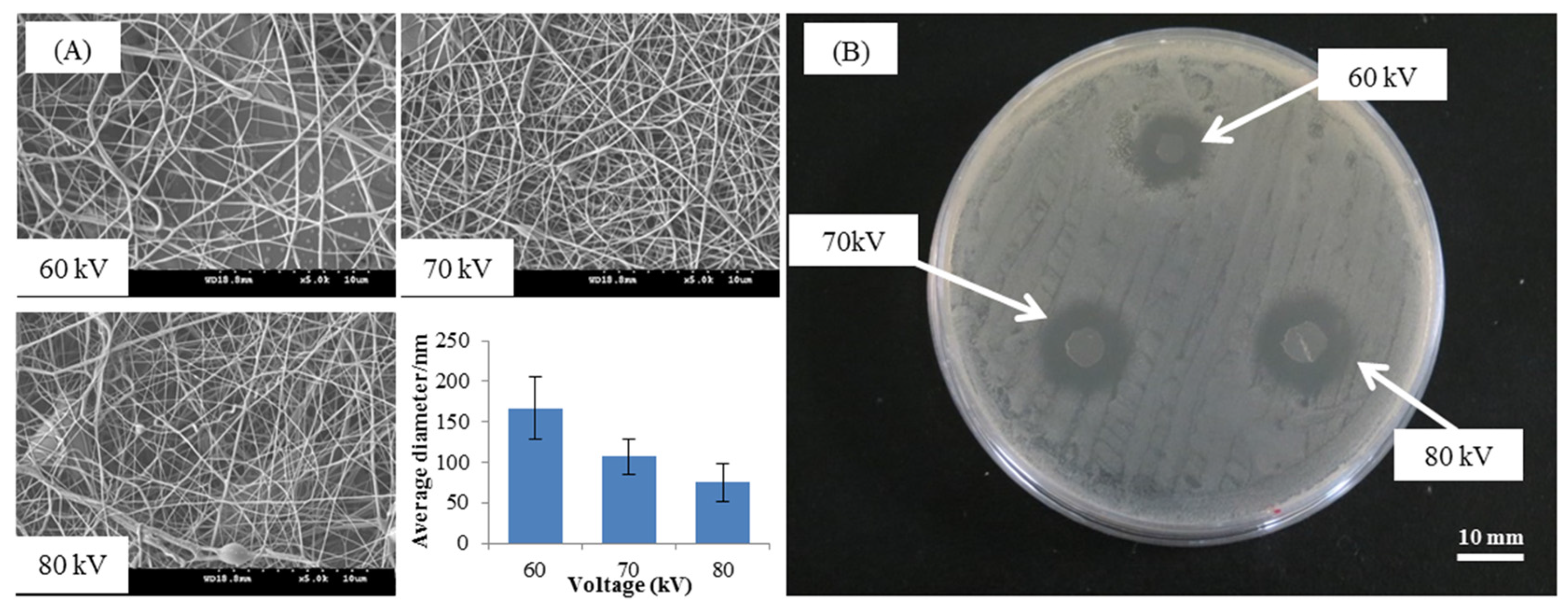
In Section 3.5, the zinc citrate content is constant as 3 wt %, and different high voltages of 60, 70, or 80 kV are applied in order to obtain nanofibers with different diameters. The antibacterial efficacy against S. aureus is then evaluated in terms of the diameter of nanofibers. Figure 7A indicates the morphology and diameter distribution of PVA/zinc citrate nanofiber mats as related to various electrospinning voltages. The nanofibers have an uneven morphology and some amount of spindle-shaped nanofibers when they are electrospun with a voltage of 60 kV. The nanofibers then have a satisfactory morphology and a smooth surface when they are electrospun by using a voltage of 70 kV. Finally, the nanofibers have some bead-structure and a smaller diameter when they are made with 80 kV. The diameter with a corresponding voltage is 167 ± 39 nm (60 kV), 107 ± 22 nm (70 kV), and 75 ± 24 nm (80 kV), as indicated in Figure 8A. The diameter of PVA/zinc citrate nanofiber mats has a decreasing trend as a result of the increasing voltage. A high voltage causes a powerful electric field force, and the Taylor cones are thus converted into a finer jet that eventually forms a finer nanofiber.
Figure 8. (A) The morphology and diameter distribution and (B) the bacterial efficacy against S. aureus of PVA/zinc citrate nanofiber mats. PVA/zinc citrate nanofiber mats are made with a specified amount zinc citrate of 3 wt % and different voltages of 60, 70, and 80 kv.
Applsci 06 00046 g008
The inhibition zones caused by the PVA/zinc citrate nanofiber mats have different sizes, as indicated in Figure 8B, indicating the voltage influences them. The diameter of inhibition zone with corresponding voltages is 8.0 ± 1 (60 kV), 9.3 ± 0.57 (70 kV), and 11.7 ± 0.5 mm (80 kV) as indicated in Table 4. Namely, the diameter of inhibition zone is proportional to the electrospinning voltage. The diameter of nanofiber becomes finer when the high voltage is increased. The nanofibers are electrospun with a zinc citrate-contained polymer solution, and thus when nanofibers are finer, they have a larger specific area that allows for a greater amount of the zinc citrate to expose, and thereby improving the antibacterial efficacy.
Table 4. Bacterial efficacy against S. aureus of PVA/zinc citrate nanofiber mats.
Amount of Zinc Citrate (wt %)Electrospinning Voltage (kV)Diameter of PVA/Zinc Citrate Nanofiber Mats (nm)Diameter of Inhibition Zone (mm)
360 167 ± 398.0 ± 1.0
370 107 ± 229.3 ± 0.6
380 75 ± 2411.8 ± 0.5

3.6. Cell Attachment and MTT Assay of PVA/Zinc Citrate Nanofiber Mats

Figure 9 shows the SEM images for the co-culture of mouse fibroblasts cells and PVA/zinc citrate nanofiber mats. Figure 9a shows the presence of many cells on the pure PVA nanofiber mats, as exemplified by their round-shape and the pseudopod. The cells attach effectively onto the mats. When zinc citrate is 0.5 wt %, the cells on the PVA/zinc citrate nanofiber mats are slightly deformed (Figure 9b). When zinc citrate is 1 wt %, cells start to stack onto the mats, and their pseudopods also adhere to the mat (Figure 9c). The cells become flat when the zinc citrate is 3 wt % (Figure 9d), which indicates a good cell attachment, whereas the cells appear stacked but do not stack when the zinc citrate is 5 wt % (Figure 9e). The SEM results have proven that PVA/zinc citrate nanofiber mats have a desired cell attachment, and the optimal cell attachment reaches their optimal state when the zinc citrate is 3 wt %. Figure 10 shows the test results of MTT assay of PVA/zinc citrate nanofiber mats. When the amount of zinc citrate is 0.5 wt % and 1 wt %, the cell viability is beyond 100%, indicating that the materials facilitate cell proliferation. This result is in the conformity with the cell attachment shown in Figure 9. Furthermore, the cell viability of 97% to 99% with the content of zinc citrate being 0.5 wt % and 1 wt %, showing the non-toxic behavior of zinc citrate against cells.
Figure 9. Cell attachment of PVA/zinc citrate nanofiber mats that contain (a) 0 wt %; (b) 0.5 wt %; (c) 1 wt %; (d) 3 wt %; and (e) 5 wt %.
Applsci 06 00046 g009
Figure 10. MTT assay result of PVA/zinc citrate nanofiber mats.
Applsci 06 00046 g010

4. Conclusions

This study successfully produces PVA/zinc citrate nanofiber mats. According to the test results, both viscosity and electrical conductivity of PVA/zinc citrate mixtures are proportional to the amount of zinc citrate. The incorporation of zinc citrate results in a fiber diameter of 70–100 nm for PVA/zinc citrate nanofiber mats. In addition, the mats also have the optimal antibacterial efficacy and cell attachment when they are made with 3 wt % zinc citrate. The test results provided in this study can be used in diverse applications in biomedical fields, health care, staple commodities, industrial nanofiber mats, and energy-saving nano products. In the future, the influence of the incorporation of different polymer solutions and needleless electrospinning technique on the formability as well as production efficiency of nanofibers can be further examined.

Acknowledgments

The authors would especially like to thank the Ministry of Science and Technology of Taiwan, for financially supporting this research under Contract MOST 104-2221-E-025-092.

Author Contributions

In this study, the concepts and designs for the experiment, all required materials, as well as processing and assessment instruments were provided by Jia-Horng Lin. Data were analyzed, and experimental results were examined by Yi-Jun Pan. The experiment were conducted and the text was composed by Kun-Chien Chiang.

Conflicts of Interest

The authors declare no conflict of interest.

References

  1. Anton, F. Process and Apparatus for Preparing Artificial Threads. U.S. Patent 1,975,504, 2 October 1934. [Google Scholar]
  2. Bhardwaj, N.; Kundu, S.C. Electrospinning: A fascinating fiber fabrication technique. Biotechnol. Adv. 2010, 28, 325–347. [Google Scholar] [PubMed]
  3. Koski, A.; Yim, K.; Shivkumar, S. Effect of molecular weight on fibrous pva produced by electrospinning. Mater. Lett. 2004, 58, 493–497. [Google Scholar]
  4. Supaphol, P.; Mit-Uppatham, C.; Nithitanakul, M. Ultrafine electrospun polyamide-6 fibers: Effect of emitting electrode polarity on morphology and average fiber diameter. J. Polym. Sci. Part B: Polym. Phys. 2005, 43, 3699–3712. [Google Scholar]
  5. Ki, C.S.; Baek, D.H.; Gang, K.D.; Lee, K.H.; Um, I.C.; Park, Y.H. Characterization of gelatin nanofiber prepared from gelatin-formic acid solution. Polymer 2005, 46, 5094–5102. [Google Scholar] [CrossRef]
  6. Agarwal, S.; Greiner, A.; Wendorff, J.H. Functional materials by electrospinning of polymers. Progress Polym. Sci. 2013, 38, 963–991. [Google Scholar]
  7. Pelipenko, J.; Kristl, J.; Janković, B.; Baumgartner, S.; Kocbek, P. The impact of relative humidity during electrospinning on the morphology and mechanical properties of nanofibers. Int. J. Pharm. 2013, 456, 125–134. [Google Scholar] [PubMed]
  8. Holzmeister, A.; Rudisile, M.; Greiner, A.; Wendorff, J.H. Structurally and chemically heterogeneous nanofibrous nonwovens via electrospinning. Eur. Polym. J. 2007, 43, 4859–4867. [Google Scholar]
  9. Varesano, A.; Carletto, R.A.; Mazzuchetti, G. Experimental investigations on the multi-jet electrospinning process. J. Mater. Process. Technol. 2009, 209, 5178–5185. [Google Scholar]
  10. Khamforoush, M.; Asgari, T. A modified electro-centrifugal spinning method to enhance the production rate of highly aligned nanofiber. Nano 2015, 10. [Google Scholar] [CrossRef]
  11. Mahalingam, S.; Edirisinghe, M. Forming of polymer nanofibers by a pressurised gyration process. Macromol. Rapid Commun. 2013, 34, 1134–1139. [Google Scholar] [PubMed]
  12. Xu, Z.; Mahalingam, S.; Rohn, J.L.; Ren, G.; Edirisinghe, M. Physio-chemical and antibacterial characteristics of pressure spun nylon nanofibres embedded with functional silver nanoparticles. Mater. Sci. Eng. C 2015, 56, 195–204. [Google Scholar]
  13. Yarin, A.; Zussman, E. Upward needleless electrospinning of multiple nanofibers. Polymer 2004, 45, 2977–2980. [Google Scholar] [CrossRef]
  14. Jirsak, O.; Sanetrnik, F.; Lukas, D.; Kotek, V.; Martinova, L.; Chaloupek, J. Method of nanofibres production from a polymer solution using electrostatic spinning and a device for carrying out the method. U.S. Patent 10/570,806, 8 September 2009. [Google Scholar]
  15. Liu, Y.; He, J.-H.; Yu, J.-Y. Bubble-electrospinning: A novel method for making nanofibers. J. Phys.: Conf. Ser. 2008, 96. [Google Scholar] [CrossRef]
  16. Wang, X.; Niu, H.; Lin, T.; Wang, X. Needleless electrospinning of nanofibers with a conical wire coil. Polym. Eng. Sci. 2009, 49, 1582–1586. [Google Scholar]
  17. Jiang, G.; Zhang, S.; Qin, X. High throughput of quality nanofibers via one stepped pyramid-shaped spinneret. Mater. Lett. 2013, 106, 56–58. [Google Scholar] [CrossRef]
  18. Cengiz-Çallıoğlu, F.; Jirsak, O.; Dayk, M. Investigation into the relationships between independent and dependent parameters in roller electrospinning of polyurethane. Textile Res. J. 2012. [Google Scholar] [CrossRef]
  19. Niu, H.; Lin, T.; Wang, X. Needleless electrospinning. I. A comparison of cylinder and disk nozzles. J. Appl. Polym. Sci. 2009, 114, 3524–3530. [Google Scholar]
  20. Lin, T.; Wang, X.; Wang, X.; Niu, H. Electrostatic spinning assembly. U.S. Patnet 13/124,742, 10 June 2014. [Google Scholar]
  21. Niu, H.; Lin, T. Fiber generators in needleless electrospinning. J. Nanomater. 2012, 2012. [Google Scholar] [CrossRef]
  22. Wang, X.; Niu, H.; Wang, X.; Lin, T. Needleless electrospinning of uniform nanofibers using spiral coil spinnerets. J. Nanomater. 2012, 2012. [Google Scholar] [CrossRef]
  23. Forward, K.M.; Rutledge, G.C. Free surface electrospinning from a wire electrode. Chem. Eng. J. 2012, 183, 492–503. [Google Scholar]
  24. Wang, X.; Hu, X.; Qiu, X.; Huang, X.; Wu, D.; Sun, D. An improved tip-less electrospinning with strip-distributed solution delivery for massive production of uniform polymer nanofibers. Mater. Lett. 2013, 99, 21–23. [Google Scholar]
  25. Liu, Y.; He, J.-H. Bubble electrospinning for mass production of nanofibers. Int. J. Nonlinear Sci. Numer. Simul. 2007, 8, 393–396. [Google Scholar]
  26. Zhou, F.-L.; Gong, R.-H.; Porat, I. Three-jet electrospinning using a flat spinneret. J. Mater. Sci. 2009, 44, 5501–5508. [Google Scholar]
  27. Wu, D.; Huang, X.; Lai, X.; Sun, D.; Lin, L. High throughput tip-less electrospinning via a circular cylindrical electrode. J. Nanosci. Nanotechnol. 2010, 10, 4221–4226. [Google Scholar] [CrossRef] [PubMed]
  28. Huang, C.; Niu, H.; Wu, C.; Ke, Q.; Mo, X.; Lin, T. Disc-electrospun cellulose acetate butyrate nanofibers show enhanced cellular growth performances. J. Biomed. Mater. Res. Part A 2013, 101, 115–122. [Google Scholar]
  29. Zhao, R.; Li, X.; Sun, B.; Zhang, Y.; Zhang, D.; Tang, Z.; Chen, X.; Wang, C. Electrospun chitosan/sericin composite nanofibers with antibacterial property as potential wound dressings. Int. J. Biol. Macromol. 2014, 68, 92–97. [Google Scholar] [PubMed]
  30. Tan, L.; Hu, J.; Zhao, H. Design of bilayered nanofibrous mats for wound dressing using an electrospinning technique. Mater. Lett. 2015, 156, 46–49. [Google Scholar] [CrossRef]
  31. He, M.; Xue, J.; Geng, H.; Gu, H.; Chen, D.; Shi, R.; Zhang, L. Fibrous guided tissue regeneration membrane loaded with anti-inflammatory agent prepared by coaxial electrospinning for the purpose of controlled release. Appl. Surf. Sci. 2015, 335, 121–129. [Google Scholar]
  32. Perez, R.A.; Kim, H.-W. Core-shell designed scaffolds for drug delivery and tissue engineering. Acta Biomater. 2015, 21. [Google Scholar] [CrossRef]
  33. Liu, Y.; Wang, R.; Ma, H.; Hsiao, B.S.; Chu, B. High-flux microfiltration filters based on electrospun polyvinylalcohol nanofibrous membranes. Polymer 2013, 54, 548–556. [Google Scholar]
  34. Cooper, A.; Oldinski, R.; Ma, H.; Bryers, J.D.; Zhang, M. Chitosan-based nanofibrous membranes for antibacterial filter applications. Carbohydr. Polym. 2013, 92, 254–259. [Google Scholar] [PubMed]
  35. Chen, W.; Liu, Y.; Ma, Y.; Liu, J.; Liu, X. Improved performance of PVdF-HFP/PI nanofiber membrane for lithium ion battery separator prepared by a bicomponent cross-electrospinning method. Mater. Lett. 2014, 133, 67–70. [Google Scholar]
  36. Wang, X.; Si, Y.; Wang, J.; Ding, B.; Yu, J.; Al-Deyab, S.S. A facile and highly sensitive colorimetric sensor for the detection of formaldehyde based on electro-spinning/netting nano-fiber/nets. Sens. Actuators B Chem. 2012, 163, 186–193. [Google Scholar]
  37. Zhou, Y.; Yang, H.; Liu, X.; Mao, J.; Gu, S.; Xu, W. Electrospinning of carboxyethylchitosan/poly(vinyl alcohol)/silk fibroin nanoparticles for wound dressings. Int. J. Biol. Macromol. 2013, 53, 88–92. [Google Scholar] [PubMed]
  38. Rai, M.; Yadav, A.; Gade, A. Silver nanoparticles as a new generation of antimicrobials. Biotechnol. Adv. 2009, 27, 76–83. [Google Scholar] [PubMed]
  39. Shalumon, K.; Anulekha, K.; Nair, S.V.; Nair, S.; Chennazhi, K.; Jayakumar, R. Sodium alginate/poly(vinyl alcohol)/nano ZnO composite nanofibers for antibacterial wound dressings. Int. J. Biol. Macromol. 2011, 49, 247–254. [Google Scholar] [PubMed]
  40. Huang, Z.-M.; Zhang, Y.-Z.; Kotaki, M.; Ramakrishna, S. A review on polymer nanofibers by electrospinning and their applications in nanocomposites. Compos. Sci. Technol. 2003, 63, 2223–2253. [Google Scholar] [CrossRef]
  41. Zuo, W.; Zhu, M.; Yang, W.; Yu, H. Experimental study on relationship between jet instability and formation of beaded fibers during electrospinning. Polym. Eng. Sci. 2005, 45. [Google Scholar] [CrossRef]
  42. Yamamoto, O. Influence of particle size on the antibacterial activity of zinc oxide. Int. J. Inorg. Mater. 2001, 3, 643–646. [Google Scholar]

