Article

A High-Thrust Screw-Type Piezoelectric Ultrasonic Motor with Three-Wavelength Exciting Mode

1
School of Mechatronic Engineering, Changchun University of Technology, Changchun 130012, China
2
School of Mechanical Science and Engineering, Jilin University, Changchun 130025, China
3
State Key Laboratory of Robotics and System, Harbin Institute of Technology, Harbin 150001, China
*
Authors to whom correspondence should be addressed.
Appl. Sci. 2016, 6(12), 442; https://doi.org/10.3390/app6120442
Submission received: 28 October 2016 / Revised: 1 December 2016 / Accepted: 13 December 2016 / Published: 16 December 2016

Abstract

:
A high-thrust screw-type piezoelectric ultrasonic motor with a three-wavelength exciting mode is proposed in this paper. The motor mainly includes a stator and a screw output shaft, and the stator is composed of twelve rectangular piezoelectric plates and a hollow metal elastomer with an internal thread. The stator can be excited to generate the combined micro ultrasonic vibration mode. With this ultrasonic vibration mode, a three-wavelength traveling wave can be synthesized. The three-wavelength traveling wave is used to drive the screw output shaft by means of the frictional force between the stator and the shaft. Rotary-linear motion can be achieved without any additional conversion mechanism. Large thrust output can be easily obtained using a three-wavelength exciting mode. The exciting mode is analyzed in detail. The prototype is designed, simulated, and fabricated. A series of experiments are carried out and the results indicate that the maximum output thrust is 50.8 N at an excitation frequency and peak-to-peak voltage of 28.9 kHz and 120 Vp-p, respectively. The maximum force density is 247.8 N/kg.

Graphical Abstract

1. Introduction

Ultrasonic motors have attracted lots of attention in the past few decades due to their distinctive characteristics such as simple structure, low speed without a reducer, self-locking in the power-off state, anti-electromagnetic interference, rapid dynamic response, etc., which make them good candidates for precise positioning systems such as aerospace mechanisms, optical instruments, micro electromechanical systems, micro robots, and so on [1,2,3,4]. The ultrasonic motor based on circumferential traveling wave vibrations is an important type of piezoelectric actuator that utilizes the inverse piezoelectric effect of piezoelectric materials to produce micro-amplitude vibrations at ultrasonic frequencies. This type of motor generally includes a stator and a rotor. The stator is composed of metal elastomer and piezoelectricelements. The driving principle of the ultrasonic motor is that a combination vibration mode can generate the traveling wave and the elliptical motion at the surface, the continuous micro-deformation motion of piezoelectric materials is converted into the rotary motion of a rotor through an intermittent friction coupling [5,6,7,8,9,10]. However, the traditional ultrasonic motor is generally designed with large preloads when applied in a precise positioning system that needs high thrust, which inevitably decreases the equipment lifespan [11,12,13]. Various types of ultrasonic actuators have been proposed for particular positioning tasks that require the high thrust as well as a compact structure under specific conditions [14,15,16,17].
As the most representative ultrasonic motors, the operating principle of the screw-type piezoelectric ultrasonic motors is similar to that of the ultrasonic motor. To date, screw-type piezoelectric ultrasonic motors have been widely researched. Some kinds of screw-type ultrasonic motors have been proposed for particular positioning tasks. Zhou et al. designed a screw-driven polyhedron linear ultrasonic motor (USM) of nut-type. The lens can be fixed in the rotor and realize an integrated design for an auto focus system that requires compact structures and low cost [18,19]. Henderson et al. presented a new linear piezoelectric motor called the SQUIGGLE motor based on ultrasonic standing wave vibrations. Precision and low cost make SQUIGGLE motors ideal for emerging micro motion applications including mobile phone cameras, micro fluidic devices [20,21]. Ho et al. proposed a piezoelectric screw-driven motor operating in two shear vibration modes. This type of motor is expected to find applications in medical industry, precision machining, small size robots, and aerospace [22]. However, the output thrust of the above reported screw-type ultrasonic motors can generally achieve several Newtons. Thus, the reported motor has difficulty performing the particular positioning tasks that need high thrust [23,24,25,26,27]. In fact, some research work has been done to improve the output thrust of the motor. Chu et al. presented a screw-thread-type ultrasonic actuator based on a Langevin piezoelectric vibrator. The actuator consisted of a threaded shaft and a transducer-formed stator. The stator based on the bolt-clamped Langevin vibrator can generate more energy and achieves high thrust at a relatively low speed. Besides, the actuator provides a long stroke corresponding to the length of the screw output shaft [28]. Hua et al. proposed a linear actuator of screw-type with double piezoelectric vibrators based on d33 mode, and the double vibrators of d33 mode can effectively generate a circumferential traveling wave within a hollow cylinder and then drive a screw rod directly through the helical surface of a nut. A larger output torque and power can be obtained relative to d31 mode piezoelectric transducers [29]. Much study is still needed to improve the output thrust of a screw-type ultrasonic motor operating at an ultrasonic frequency.
In this paper, a high-thrust screw-type ultrasonic motor with a three-wavelength exciting mode is presented. The presented motor includes a stator with internal threads and a screw output shaft with external threads that engage with the internal threads of the stator. A combined circumferential-axial bending vibration mode is excited, which includes the first and the third bending vibration modes along the axial direction and circumferential direction, respectively. A three-wavelength traveling wave can be synthesized by means of the combined bending vibration mode. The three-wavelength traveling wave is analyzed in detail. The motor is designed and its vibration performance is tested. The prototype is fabricated and its experimental system is established. The testing results indicate that a motor with a three-wavelength exciting mode is feasible and the motor excited by this exciting mode can achieve a high-output thrust.

2. Structure and Operating Principle

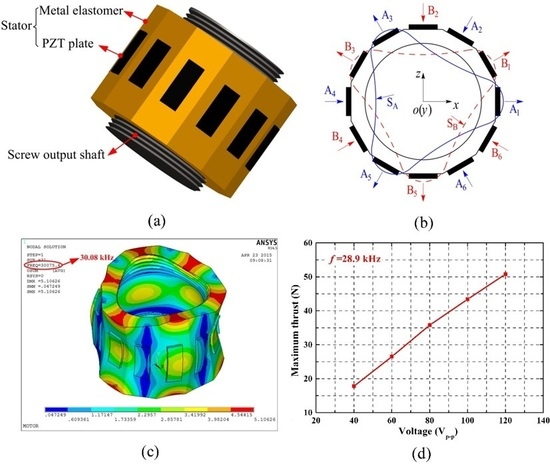
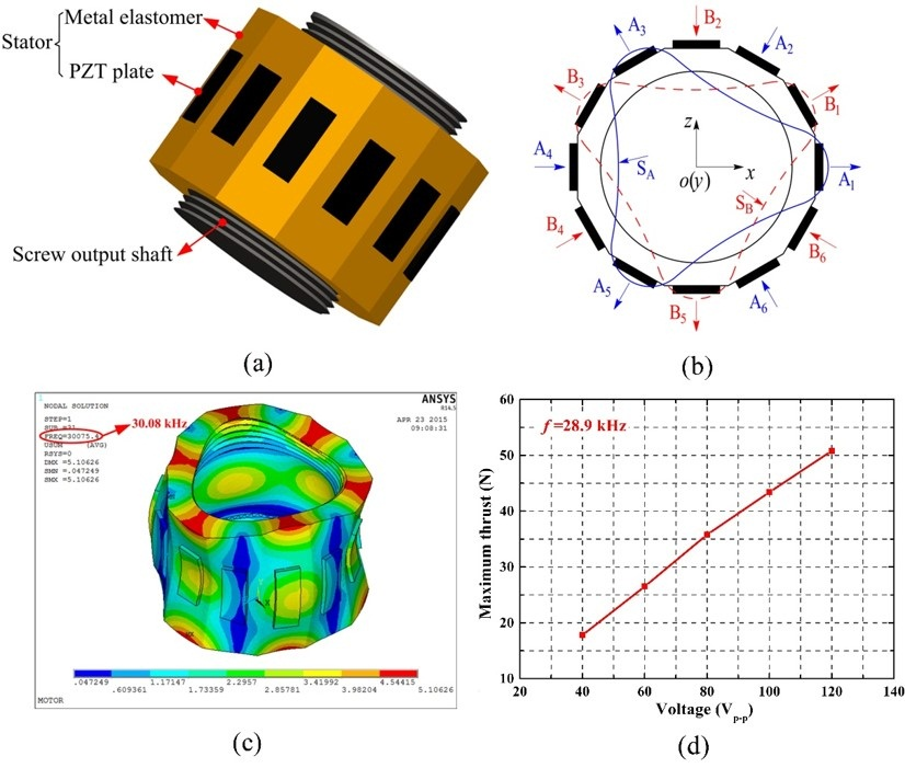
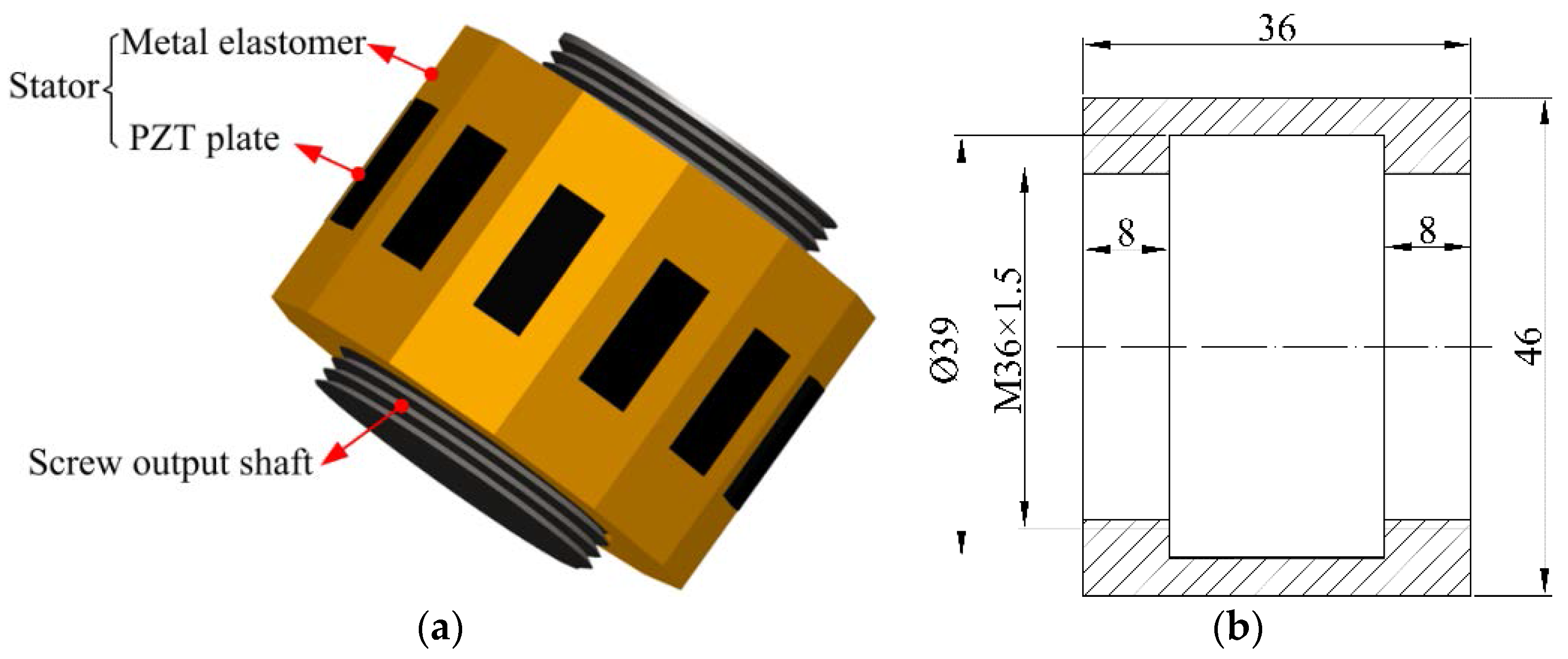
2.1. The Structureof the Screw-Type Ultrasonic Motor

The structure of the screw-type piezoelectric ultrasonic motor with a three-wavelength exciting mode is shown in Figure 1. The motor comprised of a stator that is a metal elastomer bonded with twelve rectangular piezoelectric plates on its external surface at 30 degree spacing, and a screw output shaft with external threads that engage with the internal threads of the stator. The material of the metal elastomer is brass. The stator is deformed by converse piezoelectric effect, and an elliptical deformation motion is generated at the contact point between a stator and a screw output shaft. The frictional effect enables the elliptical deformation motion of the stator to drive the external threads of the screw output shaft to rotate, so the screw output shaft implements the linear motion. The three-dimensional model of the motor is shown in Figure 1a.
In the design process, the different dimensions parameters have the great influence on the vibration mode of the motor, such as the variable L, d, and so on. The variable L is defined by the length of the stator along to the axial direction, and the value of L is equal to 36 mm in this paper. The variable d is defined by the pitch diameter of the inner thread of the stator. In this paper, a combined circumferential-axial vibration mode of the stator is excited, which includes the first and the third bending vibration modes along the axial and circumferential directions, respectively. A three-wavelength traveling wave can be synthesized by this combined vibration mode. The three-wavelength traveling wave is used to drive the screw output shaft by frictional force between the stator and screw output shaft. The designed stator includes the twelve piezoelectric plates and the metal elastomer. By calculation, the volume ratio of twelve rectangular piezoelectric plates and metal elastomer is about 1:25. The influence of the twelve piezoelectric plates can be ignored. The stator is approximated as a homogeneous material. In addition, the three-wavelength traveling wave is located at the thread pitch diameter of the metal elastomer. Thus, the main dimension relationships of the designed stator are supposed to satisfy the following calculation process.
The detailed calculation process of the first bending vibration mode of the stator along the axial direction is as follows:
L = λ
The detailed calculation process of the third bending vibration mode of the stator along the circumferential direction is as follows:
π d = 3 λ
According to the above equations, the design principle of the motor can be obtained, and the main dimensions are supposed to satisfy the following calculation equation:
L = π d 3
where the λ is the wavelength of the bending vibration mode of the stator, the L is the length of the stator along to the axial direction, and the d is the pitch diameter of the thread of the stator.
According to the design principle, the main design dimensions of the motor can be calculated, as shown in Figure 1b.The dimension parameters of the stator are designed as follows: The dimension of the thread used in elastomer is M 36×1.5, which means that the thread type is common metric triangular thread, and the nominal diameter and thread step are 36 mm and 1.5 mm, respectively. The length of the elastomer in axial direction is 36 mm, and the outside diameter of the elastomer is 46 mm. The inner diameter of the hollow cylinder of elastomer is 39 mm. In addition, the length, width and thickness dimensions of rectangular piezoelectric plates are 16 mm, 6 mm, 1 mm respectively. According to references [30,31], the length of piezoelectric plates is relative to the force factor. Under same voltage, the larger force factor can improve the output thrust. Further, the output performance of the motor can also be improved. In our previous work, such as reference [32], we can conclude that the force factor of the stator is relative to the piezoelectric plates’ distribution position, the length of the piezoelectric plates, and so on. The piezoelectric plates should be disposed on the wave loop of the first bending vibration. In this paper, the stator length is 36 mm. Thus, the distance between the Node 1 and Node 2 in the stator is 18 mm. In addition, considering the installation and fasten of the stator, the overall length of the piezoelectric plates cannot be more than the distance of two vibration nodes. Therefore, the piezoelectric plate length can be determined, and its length is 16 mm.

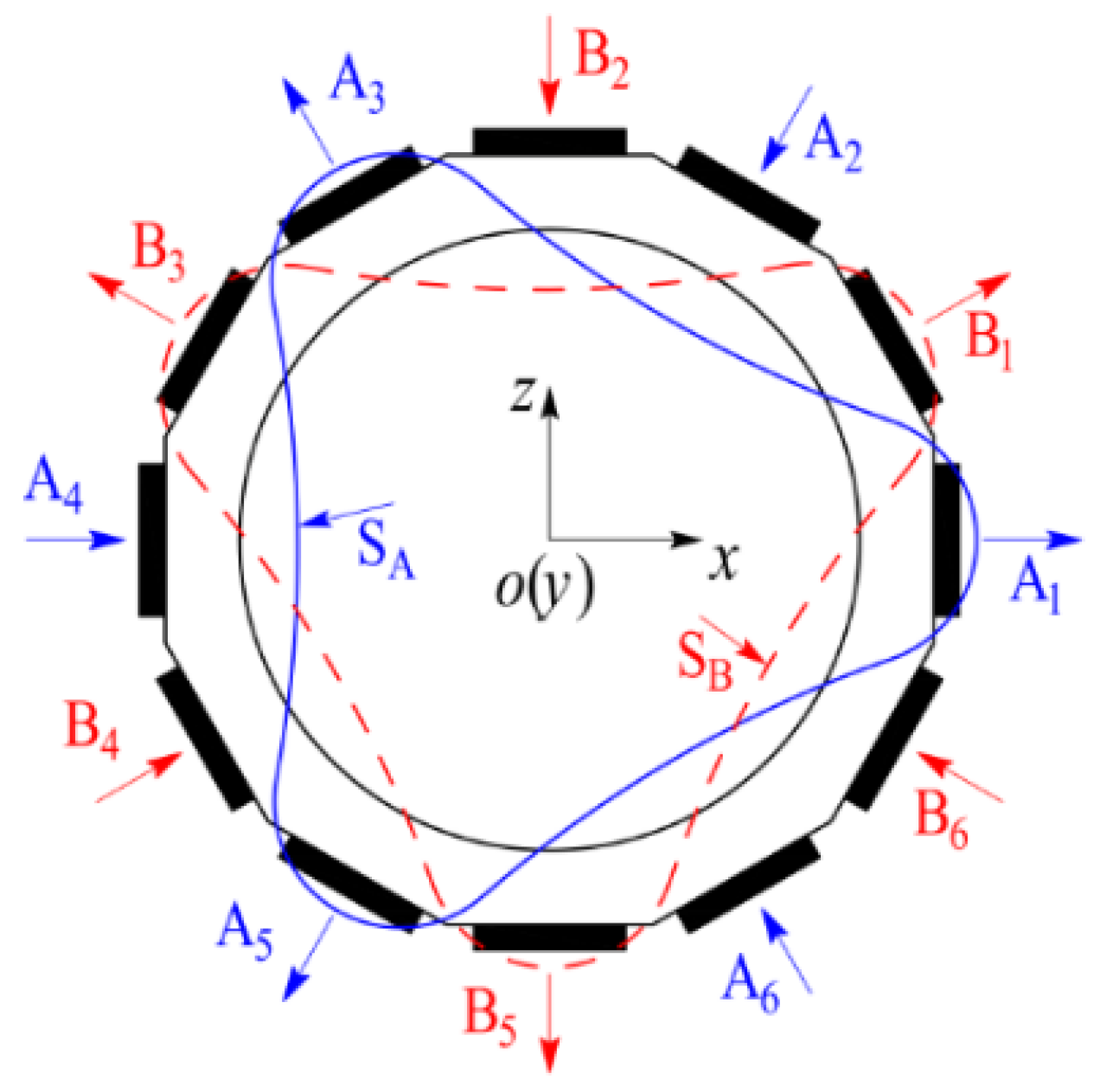
2.2. Operating Principle of ScrewTtype Ultrasonic Motor

The operating principle of the screw-type piezoelectric ultrasonic motor is shown in Figure 2. The proposed motor is drive based on the three-wavelength exciting mode. The three-wavelength exciting mode of the proposed ultrasonic motor can be achieved by the first and third bending vibration modes along the axial and circumferential directions, and the three-wavelength travelling wave can be synthesized by the three-wavelength exciting mode. In order to excite the motor to produce the three-wavelength travelling wave and the elliptic trajectory for driving rotation of the rotor on the surface points of the stator, proper combination of the piezoelectric plates is needed. The twelve rectangular piezoelectric plates are polarized in the direction of thickness and the d31 working mode is adopted by the twelve rectangular piezoelectric plates, respectively. The twelve rectangular piezoelectric plates are divided into two groups. Six rectangular piezoelectric plates, from the A1 to A6, constitute exciting group A. Exciting group B includes the remaining six rectangular piezoelectric plates, B1to B6. Simultaneously, the metal elastomer with the internal threads is connected with the ground lead. The standing wave vibrations SA and SB with three crests and troughs can be generated by the exciting signals U0sinωt and U0sin(ωt + φ), respectively. The frequency of the exciting groups A and B is supposed to be coincident with resonant frequency of the stator. During the working process of the motor, the three-wavelength exciting mode can drive the motor by means of the three contact points between the stator and the screw output shaft touched at the same time. The rotary motion can be converted into linear motion by using the screw output shaft, and the torque is converted into linear thrust. Above all, the linear thrust can be magnified by the three-wavelength travelling wave, because the effective contact area between the stator and the screw output shaft is increased. Specifically, when a small linear thrust is applied to the shaft to generate a torque, and the torque will be converted into a large thrust. When the phase shift between the exciting groups A and B is 90°, a three-wavelength travelling wave can be synthesized by standing wave vibrations SA and SB. Thus, the screw output shaft can be directly rotated to realize forward output motion. When the phase shift between exciting groups A and B is 270°, the reversed output motion can be obtained. Here, the “arrow” represents the polarized direction of the rectangular piezoelectric plates.

3. Finite Element Analysis

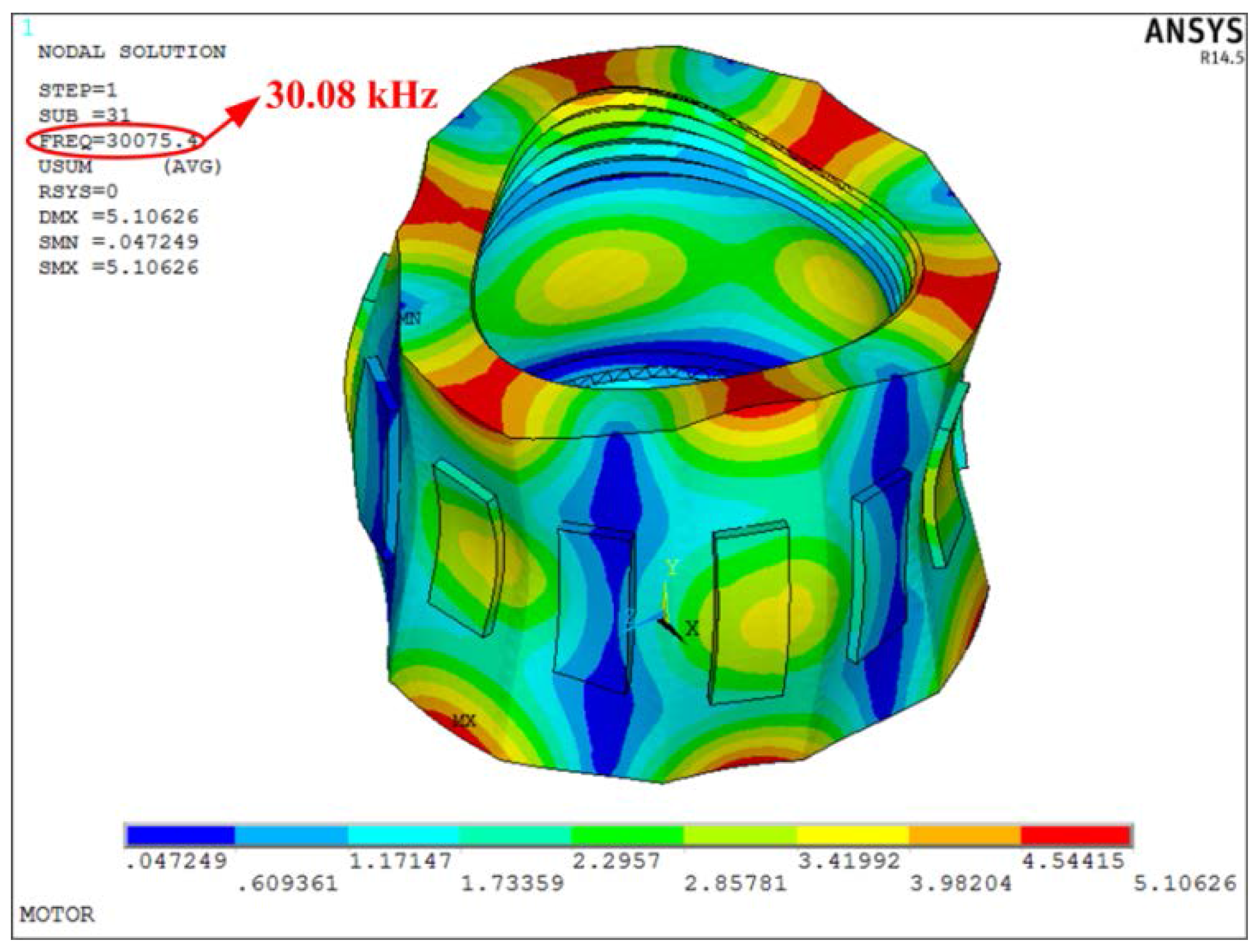
3.1. Modal Simulation of the Stator

The structure of the stator includes the twelve rectangular piezoelectric plates and the hollow metal elastomer with internal thread. The vibration characteristics of the stator are analyzed using Finite Element Method (FEM). During the simulation, some important parameters are set as follows: The Young’s modulus E, Poisson ratio σ, and mass density ρ of the metal elastomer are 90 GPa, 0.33, 8900 kg/m3, respectively. The PZT-4 typeis adopted for rectangular piezoelectric plates (Bao Ding Hong Sheng Acoustics Electron Apparatus Co., Ltd., Baoding, China). The density of the twelve rectangular piezoelectric plates is 7500 kg/m3. The other mechanical and physical parameters of the rectangular piezoelectric plates are listed in Table 1.
The element types SOLID5 and SOLID45 were used for twelve rectangular piezoelectric plates and the brass, respectively. A finite element model of the stator for the screw-type piezoelectric ultrasonic motor was established in ANSYS 14.5 (ANSYS Inc, Canonsburg, PA, USA). A modal analysis was carried out. It should be noted that the stator adopts the free-free beam. The d31 working mode is adopted for the twelve rectangular piezoelectric plates. Meanwhile, no voltage was applied on the piezoelectric plates. The glue layers between the metal elastomer and piezoelectric plates were neglected, which are too thin to be meshed and the deviations are acceptable. Free meshing and mapped meshing were adopted for the metal elastomer and the rectangular piezoelectric plates, respectively. The Block Lanczos Method was employed to extract the mode shapes and the resonant frequencies, as shown in Figure 3. Simulation result indicates the combined circumferential-axial mode of the stator can be excited and the resonant frequency of the stator is about 30.08 kHz. The simulation result provides an important reference for the selection of the resonant frequency in the three-wavelength exciting mode.

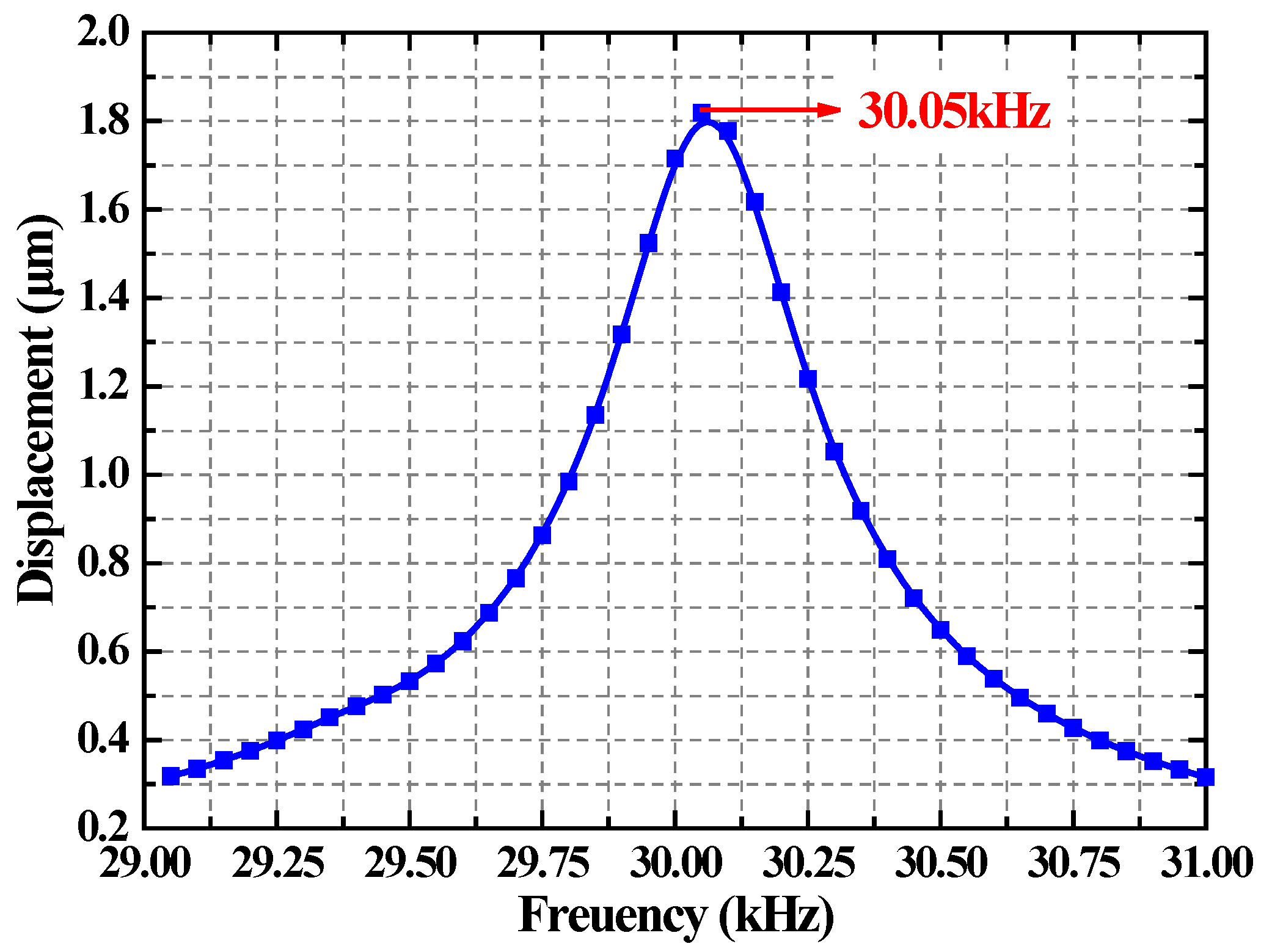
3.2. Harmonic Response Analysis of the Stator

In order to study the steady state response of the stator under aperiodic sinusoidal signal, a harmonic response analysis is carried out to obtain the vibration characteristics of the stator. The voltage of the exciting group A and the exciting group B are all 100 Vp-p. According the results of the modal simulation of the stator, the resonant frequency of the stator is about 30.08 kHz, as shown in Figure 3. Based on this, the harmonic response analysis is carried on when the frequency range is from 29 to 31 kHz. Taking a particle in the stator end as the object of study, the vibration amplitude of the particle above the exciting frequency range is extracted. The simulation result on the vibration amplitude versus frequency is shown in Figure 4. From the simulation curve, the larger vibration amplitude of the stator can be obtained when the frequency is 30.05 kHz. Thus, the resonant frequency of the stator is 30.05 kHz.

4. Fabrication and Measurement

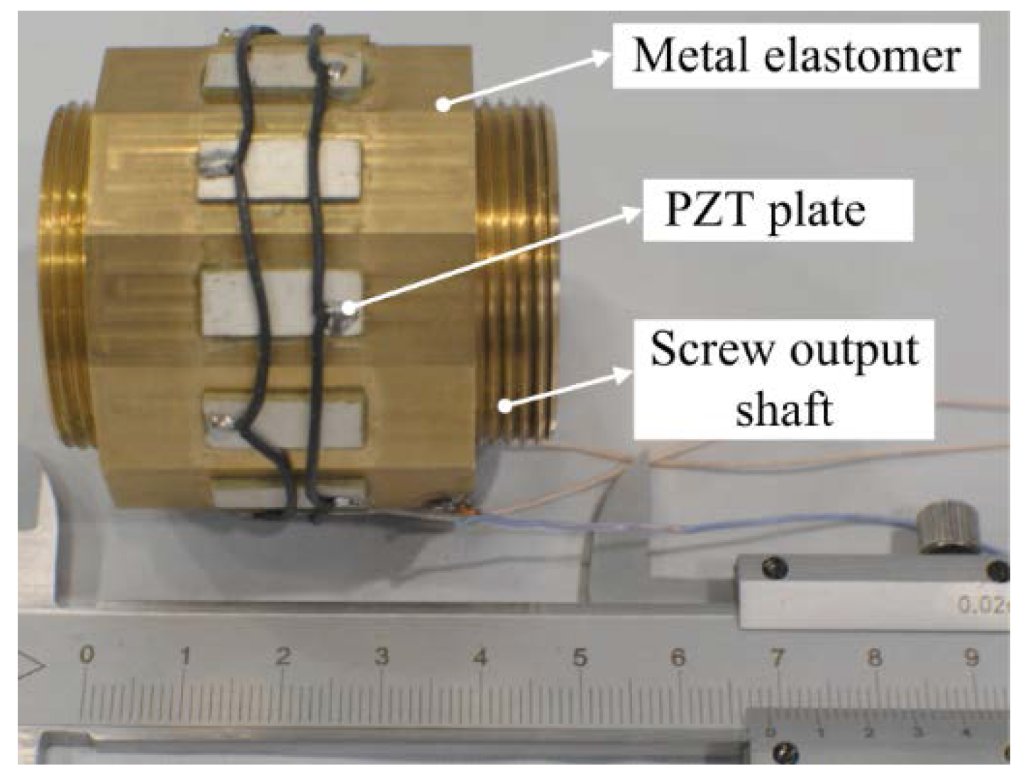
4.1. The Prototype of Screw-Type Ultrasonic Motor

To validate the feasibility of the proposed screw-type piezoelectric ultrasonic motor, a prototype of the screw-type piezoelectric ultrasonic motor was fabricated, as shown in Figure 5. The prototype mainly includes three parts: The metal elastomer, the rectangular piezoelectric plates and the screw output shaft. The metal elastomer and the twelve rectangular piezoelectric plates constitute the stator. The stator can be excited to generate the micro-amplitude ultrasonic vibrations. By means of this ultrasonic vibration, a three-wavelength traveling wave can be synthesized. The three-wavelength traveling wave is used to drive the screw output shaft by the friction force between a stator and a screw output shaft. The rotary-linear motion is achieved without the additional conversion mechanism. A series of experiments were taken to test the output characteristics of the proposed screw-type piezoelectric ultrasonic motor.

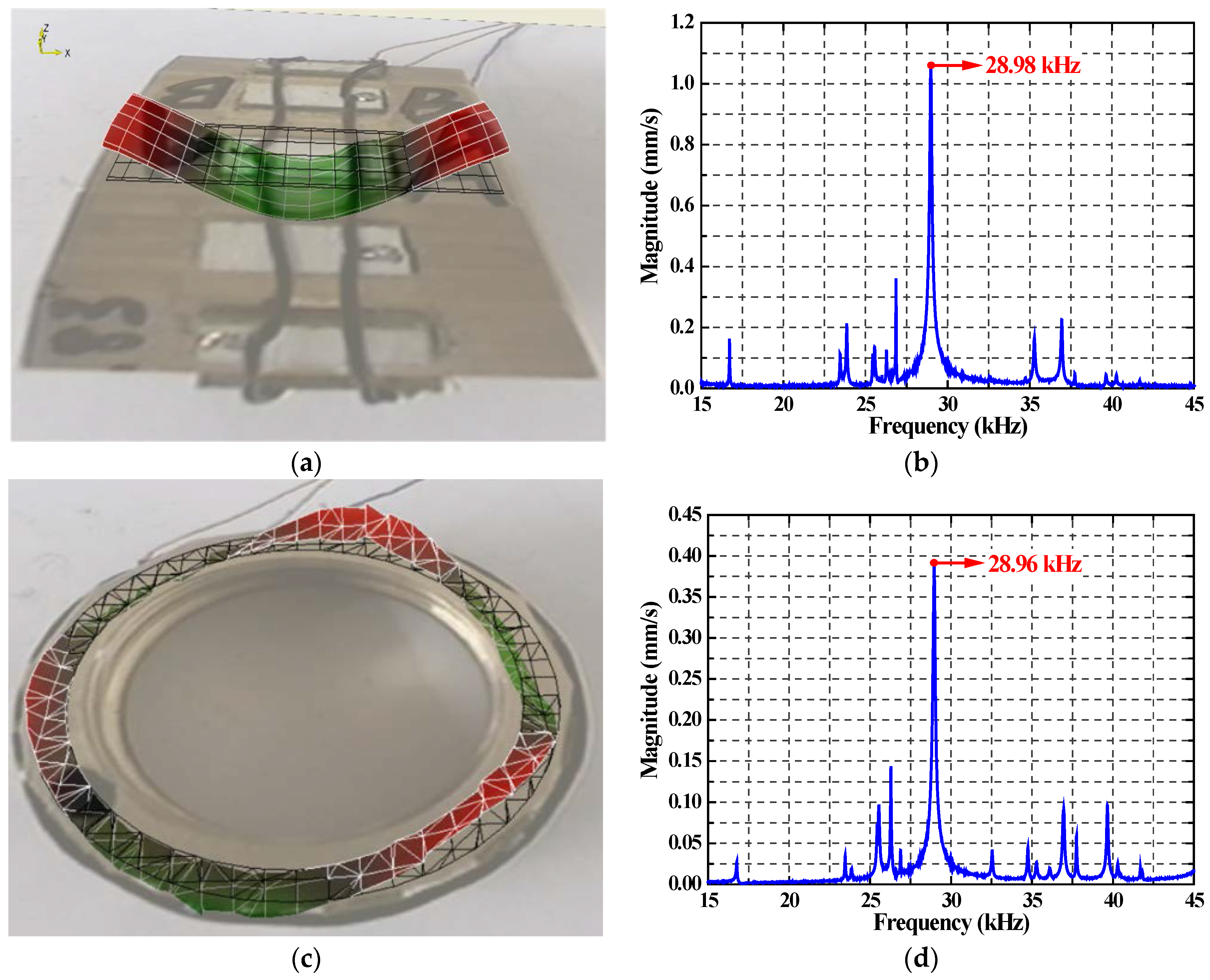
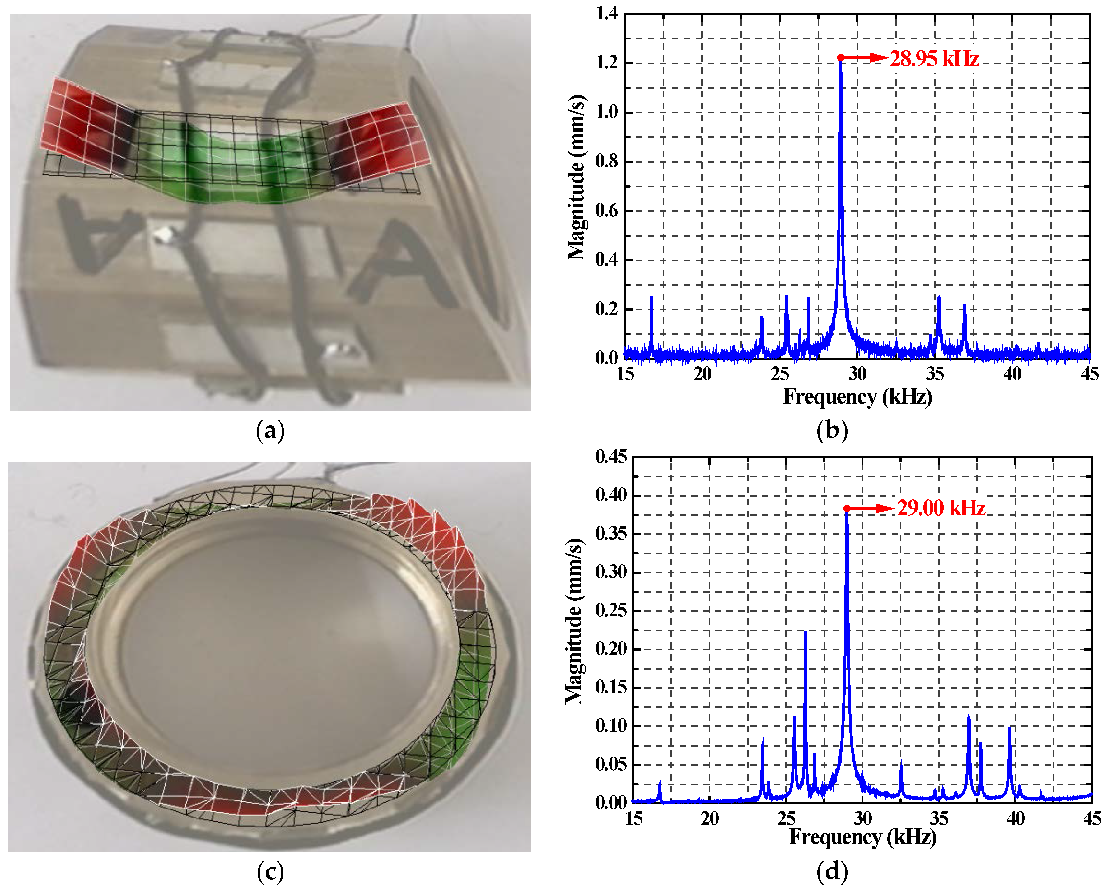
4.2. Vibration CharacteristicsMeasurement

A scanning laser Doppler vibrometer (PSV-400-M2, Polytec, Waldbronn, Germany) was used to measure the vibration performance of the motor. The outside surfaces and the end surfaces were chosen as the testing surfaces. The vibration mode shapes and vibration velocity average response spectrums under the excitations of the exciting group A is shown in Figure 6. The results indicate that the stator was excited to generate a combined circumferential-axial vibration mode. The combined vibration mode includes the first bending vibration mode along the axial direction seen in Figure 6a and the third bending vibration mode along the circumferential direction seen in Figure 6c, respectively. The tested vibration shapes of the motor agree well with the working modal shape of the stator, as shown in Figure 3. Figure 6 also states that the resonant frequencies of the axial and the circumferential vibration modes by means of the exciting group A are 28.95 kHz and 29.00 kHz, as shown in Figure 6b,d.
Figure 7 shows the vibration mode shapes and the vibration velocity average response spectrums by means of the exciting group B. The stator was excited to generate a combined circumferential–axial mode. The first and third bending vibration mode along the axial and circumferential direction is excited shown by Figure 7a,c. The resonant frequencies of the axial and the circumferential vibration modes by the exciting group B are 28.98 kHz and 28.96 kHz asseen in Figure 7b,d. From the Figure 4, it can be seen that the resonant frequency by harmonic response analysis is 30.05 kHz. Thus, the tested results have a good consistency with harmonic response analysis results. There is a slight deviation between the simulation and the experiment results. The reasons for deviation may be concluded as follows: (1) parameter discrepancies between the real material properties and ideal models; (2) diminishment of finite element model results with the increased resonant frequency that may be caused by the neglect of the glue layer; (3) the fabrication and assembly errors.

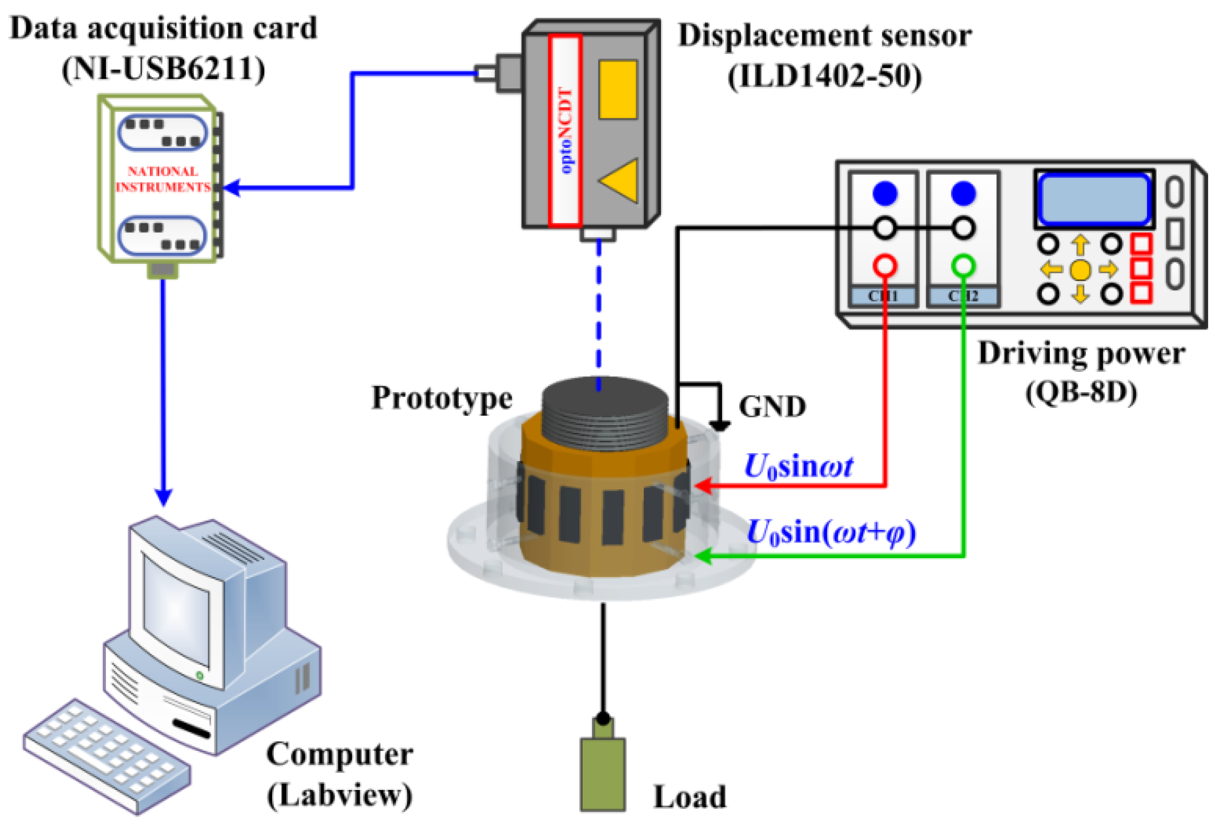
4.3. The Established Experiment System

To investigate the output characteristics of the proposed screw-type piezoelectric ultrasonic motor, an experimental tested system was established as seen in Figure 8. The tested system includes a computer, a data acquisition card (NI-USB6211, National Instruments, Austin, TX, USA), a displacement sensor (ILD1402-50, Micro-epsilon, Ortenburg, Germany), a driving power (QB-8D, Harbin, China), a prototype, and the load. It needs to be pointed out here that the prototype can be clamped tightly through the screw bolts at the nodes of the first bending vibration mode. Thus, the effect of clamping on vibration of elastomer at the nodes is neglected. It need to be pointed out here, the GND in this experiment system represented that the metal elastomer with the internal threads is connected with the ground lead. When the tested system works, the driving power generates two orthogonal signals to excite the designed prototype, and the prototype is excited to generate the continuous output motion. The load is used to measure the output performance of the motor under the various thrust forces and the decoupling of rotary–linear motion can be realized by means of the bearing mechanism. A displacement sensor is employed to measure the output motion characteristics of the prototype. The experimental data are gathered and processed through the data acquisition card, which is controlled by the computer.

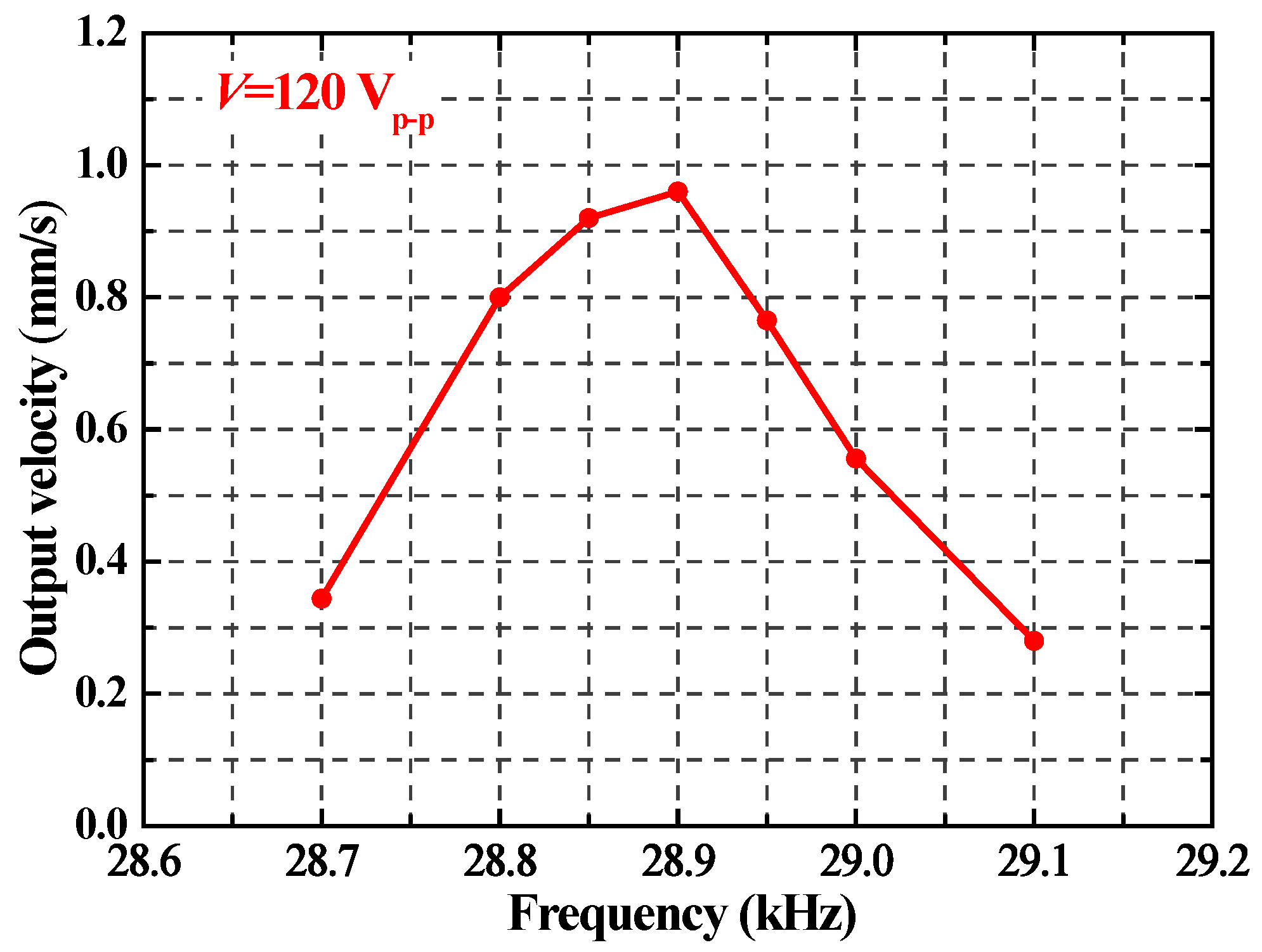
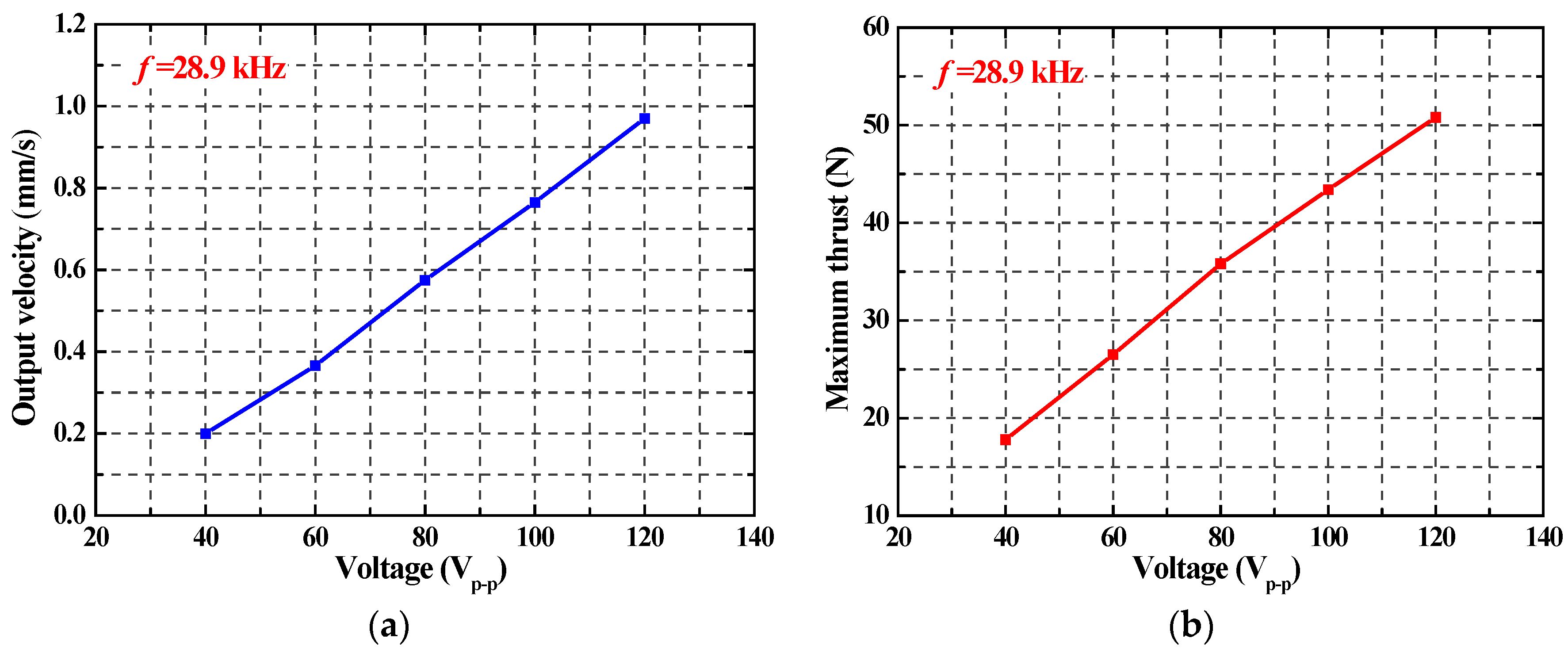
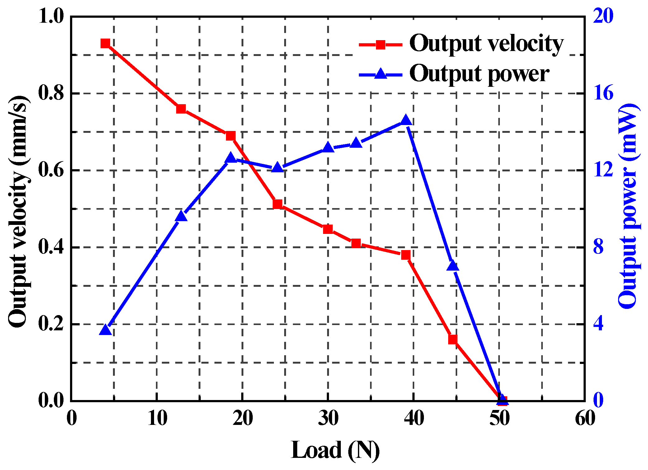
4.4. Results and Discussion

Figure 9 shows the frequency characteristics of the proposed screw-type piezoelectric ultrasonic motor under a load of 4 N. When the peak-to-peak voltage is 120 Vp-p, the output velocity of the motor increases with the increased excitation frequency until it reaches 0.96 mm/s at the frequency of 28.9 kHz, and then it drops quickly. The results indicate that the prototype works steadily and continuously when the frequencies are from 28.7 to 29.1 kHz. The maximum output velocity was gained at the resonant frequency of 28.9 kHz. Compared with the simulation and tested results, there is also a slight deviation that may be caused by fabrication and assembly errors, measurement error, and so on. Thus, the exciting frequency of the motor of 28.9 kHz is chosen as the input frequency parameter in subsequent experiments.
Figure 10 plots the voltage characteristics of the screw-type piezoelectric ultrasonic motor. The output velocity of the motor is tested at the resonant frequency of 28.9 kHz, as shown in Figure 10a. The peak-to-peak voltages are from 40Vp-p to 120Vp-p and the phase shift of the excitation signals is 90°. The output velocity increases obviously with the increase of driving voltage and a well linear relationship can be observed. The results indicate that the output velocities are 0.2 mm/s and 0.97 mm/s when peak-to-peak voltages are40Vp-p and 120Vp-p. Figure 10b shows that the relationship between the peak-to-peak voltages and maximum thrust. The curve of the maximum thrust follows a linear increased tendency with the increased peak-to-peak voltage, but is not an ideal straight line. The maximum thrusts are 17.8 N and 50.8 N under the peak-to-peak driving voltage of 40Vp-p and 120Vp-p, respectively.
Figure 11 shows the load characteristics curve of the screw-type piezoelectric ultrasonic motor when the peak-to-peak voltage, excitation frequency, and phase shift are120Vp-p, 28.9 kHz and 90°, respectively. The output velocity rapidly decreases with the increasing load, and the motor cannot work normally when the load reaches 50.4 N. The output power curve of the actuator is also observed in Figure 11. The output power increases with the increasing load until it reaches 14.56 mW at the load of 39 N, and then the output power of the motor decreases rapidly. The force density of the motor is 247.8 N/kg, compared with the force density of 149.8 N/kg of the screw-type ultrasonic motor under the high exciting voltage of 250 Vp-p for 34.5 kHz in the reference [27].Thus, the proposed motor excited by the three-wavelength exciting mode can meet the specific conditions that require high thrust as well as a compact structure.

5. Conclusions

A high-thrust screw-type ultrasonic motor with a three-wavelength exciting mode is proposed in this paper. The motor mainly includes a stator and a screw output shaft. The stator is excited by a three-wavelength traveling wave. The contact area between the stator and the screw output shaft is increased and the maximum thrust of the motor is clearly improved. The operation process of the motor with athree-wavelength exciting mode is discussed in detail. A prototype is simulated, designed, fabricated and tested. The testing results indicate that the designed three wavelength exciting mode is feasible. The output velocity can reach 0.97 mm/s with the load of 4 N when the peak-to-peak voltage and the excitation frequency are 120 Vp-p and 28.9 kHz. The maximum output thrust of the motor is 50.8 N when the driving voltage and the excitation frequency are120Vp-p and 28.9 kHz. The force density of the motor is 247.8 N/kg. Thus, the proposed screw-type piezoelectric ultrasonic motor with the three-wavelength exciting mode has the most promising application prospects in large load conditions.

Acknowledgments

This study was financially supported by the Jilin Province Science and Technology Development Plan Item (Project No.20150312006ZG), the State Key Laboratory of Robotics and System (HIT) (Project No. SKLRS-2016-KF-14), the Science and Technology Research Planning Project of the Education Department of Jilin Province (Project No.2016332) and Key Projects of Science and Technology Development Plan of Jilin Province (Project No. 20160204054GX).

Author Contributions

All authors conceived and designed the experiments and analyzed the data; Hengyu Li designed and fabricated the prototype. Liang Wang accomplished the simulation analysis of the prototype. Tinghai Cheng conceived the idea. Meng He conducted the measurements of the prototype and prepared figures. Hongwei Zhao and Haibo Gao supervised the experiments and contributed to manuscript preparation. All authors discussed the progress of research and reviewed the manuscript.

Conflicts of Interest

The authors declare no competing financial interests.

References

  1. Mashimo, T.; Toyama, S. Rotary-linear piezoelectric micro actuator with a cubic stator of side length 3.5 mm. IEEE Trans. Ultrason. Ferroelectr. Freq. Control 2010, 57, 1825–1830. [Google Scholar] [CrossRef] [PubMed]
  2. Liu, Y.; Xu, D.; Yang, X.; Chen, W. Miniaturized piezoelectric actuator operating in bending hybrid modes. Sens. Actuators A 2015, 235, 015112. [Google Scholar] [CrossRef]
  3. Liu, Y.; Chen, W.; Yang, X.; Liu, J. A T-shape linear piezoelectric motor with single foot. Ultrasonics 2015, 56, 551–556. [Google Scholar] [CrossRef] [PubMed]
  4. Shi, Y.; Zhao, C. Simple new ultrasonic piezoelectric actuator for precision linear positioning. J. Electroceram. 2012, 28, 233–239. [Google Scholar] [CrossRef]
  5. Koc, B.; Cagatay, S.; Uchino, K. A piezoelectric motor using two orthogonal bending modes of a hollow cylinder. IEEE Trans. Ultrason. Ferroelectr. Freq. Control 2002, 49, 495–500. [Google Scholar] [CrossRef] [PubMed]
  6. Dong, S.; Lim, S.; Lee, K.; Zhang, J.; Lim, L.; Uchino, K. Piezoelectric ultrasonic micromotor with 1.5 mm diameter. IEEE Trans. Ultrason. Ferroelectr. Freq. Control 2003, 50, 361–367. [Google Scholar] [CrossRef] [PubMed]
  7. Vyshnevskyy, O.; Kovalev, S.; Mehner, J. Coupled tangential-axial resonant modes of piezoelectric hollow cylinders and their application in ultrasonic motors. IEEE Trans. Ultrason. Ferroelectr. Freq. Control 2005, 52, 31–36. [Google Scholar] [CrossRef] [PubMed]
  8. Chen, W.; Liu, Y.; Yang, X.; Liu, J. Ring-type traveling wave ultrasonic motor using a radial bending mode. Ultrason. Ferroelectr. Freq. Control 2014, 61, 197–202. [Google Scholar] [CrossRef] [PubMed]
  9. Mashimo, T.; Terashima, K. Experimental verification of elliptical motion model in traveling wave ultrasonic motors. IEEE/ASME Trans. Mech. 2015, 20, 1–9. [Google Scholar] [CrossRef]
  10. Watson, B.; Friend, J.; Yeo, L. Piezoelectric ultrasonic micro/milli-scale actuators. Sens. Actuators A 2009, 152, 219–233. [Google Scholar] [CrossRef]
  11. Egashira, Y.; Kosaka, K.; Iwabuchi, T.; Kosaka, T.; Baba, T.; Endo, T.; Hashiguchi, H.; Harada, T.; Nagamoto, K.; Watanabe, M.; et al. Sub-nanometer resolution ultrasonic motor for 300 mm waferlithography precision stage. Jpn. J. Appl. Phys. 2002, 41, 5858–5863. [Google Scholar] [CrossRef]
  12. Zhang, Y.; Zhang, W.; Hesselbach, J.; Kerle, H. Development of a two-degree-of-freedom piezoelectric rotary-linear actuator with high driving force and unlimited linear movement. Rev. Sci. Instrum. 2006, 77, 035112. [Google Scholar] [CrossRef]
  13. Li, H.; Quan, Q.; Deng, Z.; Hua, Y.; Wang, Y.; Bai, D. A novel noncontact ultrasonic levitating bearing excited by piezoelectric ceramics. Appl. Sci. 2016, 6, 280. [Google Scholar] [CrossRef]
  14. Huang, H.; Fu, L.; Zhao, H.; Shi, C.; Ren, L.; Li, J.; Qu, H. A novel rotary actuator driven by only one piezoelectric actuator. Rev. Sci. Instrum. 2013, 84, 096105. [Google Scholar] [CrossRef] [PubMed]
  15. Shao, S.; Shi, S.; Chen, W.; Liu, J.; Liu, Y. Research on a linear piezoelectric actuator using T-Shape transducer to realize high mechanical output. Appl. Sci. 2016, 6, 103. [Google Scholar] [CrossRef]
  16. Liu, Y.; Xu, D.; Yu, Z.; Yan, J.; Yang, X.; Chen, W. A novel rotary piezoelectric motor using first bending hybrid transducers. Appl. Sci. 2015, 5, 472–484. [Google Scholar] [CrossRef]
  17. Yuan, S.; Zhao, Y.; Chu, X.; Zhu, C.; Zhong, J. Analysis and experimental research of a multilayer linear piezoelectric actuator. Appl. Sci. 2016, 6, 225. [Google Scholar] [CrossRef]
  18. Zhou, T.; Chen, Y.; Lu, C.; Fu, D.; Hu, X.; Li, Y. A nut-type ultrasonic motor and its application in the focus system. Sci. China Ser. E-Technol. Sci. 2009, 52, 2591–2596. [Google Scholar] [CrossRef]
  19. Zhou, T.; Chen, Y.; Lu, C.; Fu, D.; Hu, X.; Li, Y.; Tian, B. Integrated lens auto-focus system driven by a nut-type ultrosonic motor (USM). Sci. China Ser. E 2009, 54, 2591–2596. [Google Scholar] [CrossRef]
  20. Henderson, D. Simple Ceramic Motor, Inspiring Smaller Products. In Proceedings of the International Conference on New Actuators, Bremen, Germany, 14–16 June 2006; pp. 1–4.
  21. Henderson, D.A. Novel piezo motor enables positive displacement micro fluidic pump. In Proceedings of the 2007 NSTI Nanotechnology Conference and Trade Show, Santa Clara, CA, USA, 20–24 May 2007; pp. 272–275.
  22. Ho, S.; Chiu, W. A piezoelectric screw-driven motor operating in shear vibration modes. J. Intell. Mater. Syst. Struct. 2016, 27, 134–145. [Google Scholar] [CrossRef]
  23. Sanguinetti, B.; Varcoe, B. Use of a piezoelectric SQUIGGLE® motor for positioning at 6 K in a cryostat. Cryogenics 2006, 46, 694–696. [Google Scholar] [CrossRef]
  24. Turowski, S.G.; Seshadri, M.; Loecher, M.; Podniesinski, E.; Spernyak, J.A.; Mazurchuk, R.V. Performance of a novel piezoelectric motor at 4.7 T applications and initial tests. Magn. Reson. Imaging 2008, 26, 426–432. [Google Scholar] [CrossRef] [PubMed]
  25. Loverich, J.; Koopmann, G.; Lesieutre, G.; Frank, J.; Chen, W. A new piezoelectric actuator using a feed-screw for quasi-static motion accumulation–Part I experimental development. J. Intell. Mater. Syst. Struct. 2008, 19, 73–81. [Google Scholar] [CrossRef]
  26. Patronik, N.; Ota, T.; Zenati, M.; Riviere, C. Synchronization of epicardial crawling robot with heart beat and respiration for improved safety and efficiency of locomotion. Int. J. Med. Robot. 2012, 8, 97–106. [Google Scholar] [CrossRef] [PubMed]
  27. Zhang, J.; Zhu, H.; Zhao, C. Contact analysis and modeling of a linear ultrasonic motor with a threaded output shaft. J. Electroceram. 2012, 29, 254–261. [Google Scholar] [CrossRef]
  28. Chu, X.; Wang, J.; Yuan, S.; Li, L.; Cui, H. A screw-thread-type ultrasonic actuator based on a Langevin piezoelectric vibrator. Rev. Sci. Instrum. 2014, 85, 065002. [Google Scholar] [CrossRef] [PubMed]
  29. Hua, S.; Meng, Y.; Lou, Y.; Li, Z.; Wang, X. Screw-type actuator driven by piezoelectric transducers. Adv. Mech. Eng. 2015, 7, 1–10. [Google Scholar] [CrossRef]
  30. Zhu, H.; Chen, C.; Zhao, C. Investigation on a cylindrical ultrasonic micromotor. Proc. CSEE 2006, 26, 128–133. (In Chinese) [Google Scholar] [CrossRef]
  31. Morita, T.; Kurosawa, M.; Higuchi, T. A cylindrical shaped micro ultrasonic motor utilizing PZT thin film (1.4 mm in diameter and 5.0 mm long stator transducer). Sens. Actuators A 2000, 83, 225–230. [Google Scholar] [CrossRef]
  32. Cheng, T.; Guo, X.; Bao, G. Research on the excitation modes of PZT element in bending cylindrical transducers. In Proceedings of the 2011 Symposium on Piezoelectricity, Acoustic Waves, and Device Applications, Shenzhen, China, 9–11 December 2011; pp. 305–309.
Figure 1. Structure of the proposed piezoelectric ultrasonic motor: (a) the three-dimensional model of the motor; (b) the main structure parameters of the stator (unit: mm).
Applsci 06 00442 g001
Figure 2. The three-wavelength exciting mode of the proposed piezoelectric ultrasonic motor.
Applsci 06 00442 g002
Figure 3. Working modal shape of the stator by Finite Element Method (FEM).
Applsci 06 00442 g003
Figure 4. Simulation result: The relationship between frequency and displacement of a particle.
Applsci 06 00442 g004
Figure 5. Prototype of the proposed piezoelectric ultrasonic motor.
Applsci 06 00442 g005
Figure 6. Vibration testing result of the motor under the exciting group A: (a) axial vibration mode shape; (b) axial vibration velocity average response spectrum; (c) circumferential vibration mode shape; (d) circumferential vibration velocity average response spectrum.
Applsci 06 00442 g006
Figure 7. Vibration testing result of the motor under the exciting group B: (a) axial vibration mode shape; (b) axial vibration velocity response spectrum; (c) circumferential vibration mode shape; (d) circumferential vibration velocity response spectrum.
Applsci 06 00442 g007
Figure 8. Schematic drawing of the experiment system.
Applsci 06 00442 g008
Figure 9. Frequency characteristics of the screw-type piezoelectric ultrasonic motor.
Applsci 06 00442 g009
Figure 10. Voltage characteristics of the screw-type piezoelectric ultrasonic motor: (a) the relationship between the driving voltages and the output velocities; (b) the relationship between the driving voltages and the maximum thrust.
Applsci 06 00442 g010
Figure 11. Load characteristics of the screw-type piezoelectric ultrasonic motor.
Applsci 06 00442 g011
Table 1. Mechanical and physical parameters of the rectangular piezoelectric plates.
DielectricCoefficientMatrix (F/m)PiezoelectricStressMatrix (C/m2)ElasticCoefficientMatrix (GPa)
[ ε ] = [ 7.30 0 0 0 7.30 0 0 0 6.35 ] × 10 9 [ e ] = [ 0 0 5.2 0 0 5.2 0 0 15.1 0 0 0 0 12.7 0 12.7 0 0 ] [ c ] = [ 139 77.8 74.3 0 0 0 77.8 139 74.3 0 0 0 74.3 74.3 115 0 0 0 0 0 0 30.6 0 0 0 0 0 0 25.6 0 0 0 0 0 0 25.6 ]

