1. Introduction
Bolt connections are widely used in many industrial fields. Bolt connections are influenced by cyclic loading and various working conditions, and the bolt connections tend to loosen. In practice, accidents have been caused by bolt looseness, and monitoring of the bolt preload force has become important in the engineering field to ensure the safety of the structures. With the development of structural health monitoring (SHM), more theories and technologies are being developed regarding bolt health monitoring and bolt looseness detection [
1].
Coin-tap is commonly used in engineering practices, including in the detection of bolt looseness. According to the change of the sound during an impact, engineers estimate whether the bolt is loosened or not. Based on this, Cawley and Adams [
2,
3] proposed a theory that structural imperfection causes the changes of the response signals, thus the structural damage can be identified according to the width of the time domain curves or the area ratio of the frequency domain. After a series of research, Xiang et al. [
4,
5] proposed a controlled tap detection method for bolt tightness based on a controlled tap detection principle, and the bolt loosening status can be determined quantitatively by using the support vector machine method. However, the tap method cannot provide real time monitoring of bolt looseness.
Piezoceramics with such attractive features as low cost, small size, wide bandwidth, and sensing and actuating functions have been widely researched in real-time active vibration control [
6,
7,
8], stress-wave based communication [
9,
10,
11], and structural health monitoring [
12,
13,
14,
15,
16]. Another attractive feature of a piezoceramic transducer is the coupling between its electric impedance and the host structure’s mechanical impedance. The piezoelectric impedance method was proposed to monitor structure health status in 1994 by Liang et al. [
17]. The analytical relationship between the piezoelectric impedance and the mechanical impedance of the host structure was established for the first time. Sopon et al. [
18] used a piezoelectric transducer (PZT) as an actuator–sensor collectively in conjunction with the numerical model-based spectral element method (SEM) in structural health monitoring to quantitatively detect damage of bolted joints. By analyzing the characteristics of the piezoelectric element under the bolt looseness condition, Gao et al. [
19] concluded that the conductance of the piezoelectric patches changes significantly under the high-frequency (more than 50 kHz) voltage excitation. Mascarenas et al. [
20] enhanced the PZT to form a washer for monitoring individual bolt looseness by examining the electro-mechanical impedance (EMI) at resonance. Nguyem et al. [
21] used multi-channel wireless impedance sensor nodes and multiple PZT-interfaces to monitor bolt loosening in bolted connection.
The ultrasonic method is employed in some SHM fields. As a valuable way to monitor bolt looseness, the ultrasonic method is continually improved by many researchers [
22]. An ultrasonic instrument for the accurate measurement of bolt stress was described by Joshi in 1984 [
23]. Sisman et al. [
24] used the ultrasonic method to quantitatively detect the preload between the bolt and the connect surface. Yasui et al. [
25] proposed an ultrasonic velocity ratio method for measuring bolt axial load. Jhang et al. [
26] used the phase detection technique to measure the TOF (time of flight) of a tone-burst ultrasonic wave; the method improved the precision of the ultrasonic velocity method for measuring bolt stress. The propagation velocity of the ultrasonic method is affected by bolt material, stress and some other factors, and it is not easy to accurately determine the axial force of the bolt. Additionally, it requires a special precision instrument for the measurement, and it is difficult to apply to real time application.
The active sensing method utilizes the sensing and actuation capability of the piezoelectric transducers. For this method, at least one pair of the PZT patches is used with one serving as an actuator to generate a stress wave and the other serving as a sensor to detect the stress wave. A damage or change along the wave propagating path will change the detect signal. As a real time method, many researchers have explored this method [
27]. Mita and Fujimoto [
28] combined the ultrasonic waves and support vector machines method to detect loosened bolts. The experiments show that the proposed methods could identify the location and the level of damage of the loosened bolts. The active sensing-based method was also used in detecting damage of the bolt on a steel bridge [
29], and some researchers applied ultrasonic and magneto-elastic active sensors in monitoring bolted joints in a satellite panel [
30].
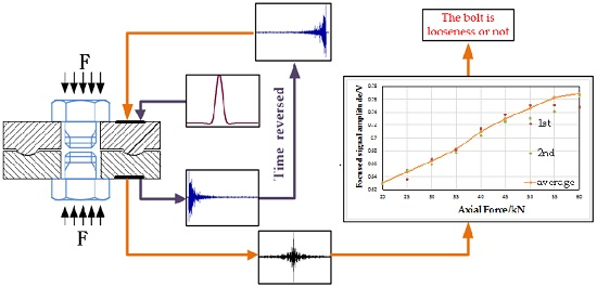
In our team’s previous studies [
31,
32], the piezoelectric active sensing method with the time reversal technique [
33] was used to monitor the bolt looseness. The time reversal method reverses the response signal that is received by the sensor in its time domain. This method can make the signal energy focus on space and time. In these studies, the peak of the time reversal focused signal can represent the wave energy that transmitted through the interface of the bolted joint, and the wave energy is proportional to the true contact area of the bolted joint interface which depends on the bolt tightening force. The experiments show that the focused signal peak amplitudes increase with the increasing blot preload until reaching saturation and the focused signal peak remains stable. When there is no more deformation space at the bolted joint interface under a certain bolt preload, the true contact area does not change any more. Besides, the surface roughness of the bolted joint affects the saturation value; the higher roughness can postpone the saturation value of the bolt preload. When it comes to bolt connection surfaces, the contact roughness is determined by the process and working condition, which cannot be increased artificially. Even if a high roughness is used, it is hard to guarantee the higher roughness precisely for a certain machining process. Therefore, in order to resolve the problem of saturation, a new monitoring structure needs to be developed. The new proposition is that of a new washer structure for monitoring bolted looseness status based on the piezoelectric active sensing method and to deal with the saturation problem. The new washer design will control the contact area artificially so that the washer can monitor the full range of the rated preload.
2. Proposed Method and Principle
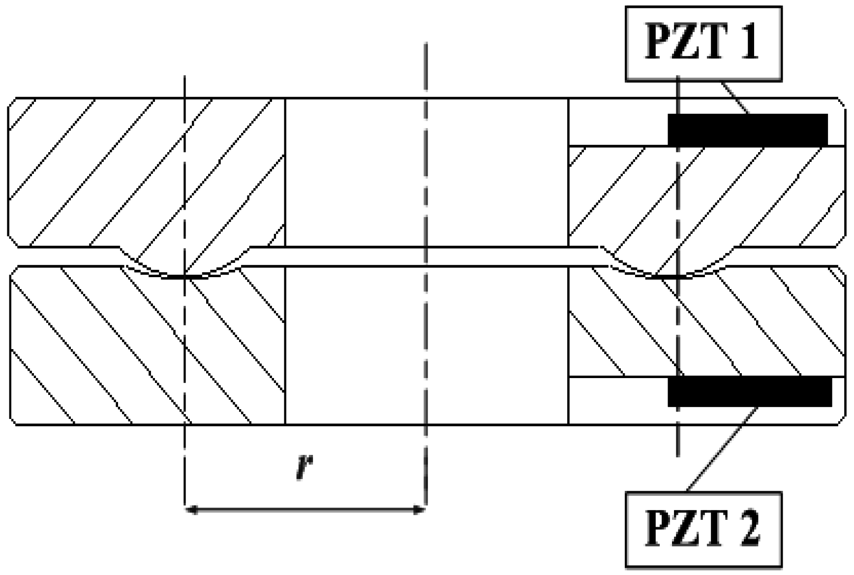
The new smart washer structure is shown in
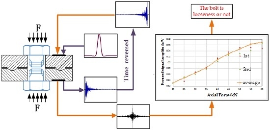
Figure 1. It is composed of two annular disks, the contact surfaces of which are machined into convex and concave, respectively. Two piezoelectric patches are bonded onto two non-contact surfaces of the proposed smart washer sensor. One piezoelectric patch serves as an actuator to generate an ultrasonic wave transmitting through the contact surface, and the other one as a sensor to detect the response signals. Furthermore, the time reversal method is employed, which can ensure a high signal to noise ratio. The first response signal is reversed in the time domain and then reemitted. Then, the reverse focused signal is detected by the sensor piezoelectric patch. In addition, based on the fact that the waves are the energy transmission and the transmitted energy is proportional to the true contact area of the bolted joint interface, the bolted loosening status can be determined by extracting the focused signal peak that has a certain relationship with the transmitted energy.
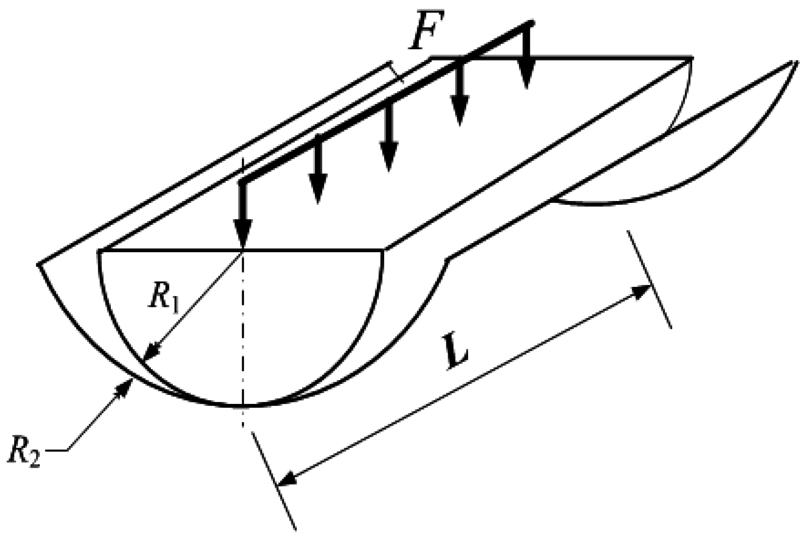
In order to describe the relationship between the contact area and loading-force, an analysis of the contact is necessary. According to the Classical Hertz contact theory, two elasticaxis-parallel cylinders’ internal contact is shown in
Figure 2; the contact surface shape of the cylinders is rectangular [
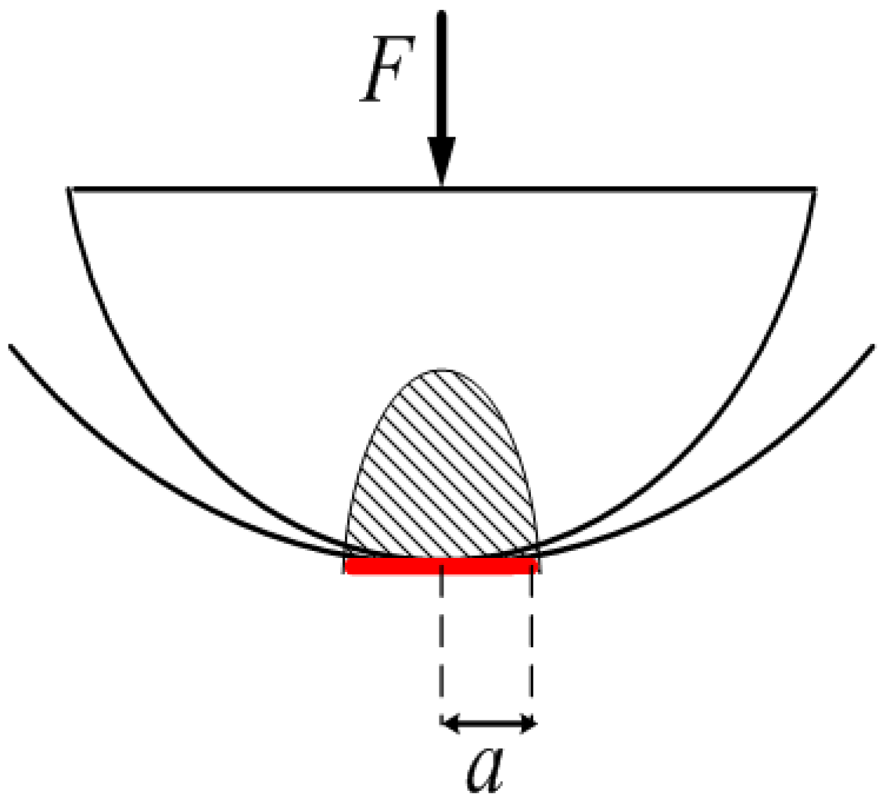
34]. Furthermore, the unit’s pressure on the contact surface is distributed in an elliptic cylindrical pattern as shown in
Figure 3. Hertz theory relates loading force
F and contact area
S as follows:
where
a is half the width of the rectangle,
L is the length of cylinders,
E1 and
E2 are the elasticity modulus of the two cylinders,
R1 and
R2 are the curvatures of the cylinders, and μ
1 and μ
2 are Poisson’s ratios.
For the smart washer in this paper, the contact area is an annulus; the existing contact formula is not applicable to this model; after the differential, the annulus can be regarded as being composed of numerous small rectangles, made up of countless small rectangles; the area of each rectangle is d
S; and the contact area,
S, can be obtained by the equation as follows:
where
r is the distance between the center of the washer and the center of the convex and concave, as shown in
Figure 1, and 2π
r is the perimeter of the annulus center.
It can be seen that the contact area is decided by the acting force when r and R are given, more specifically, the area will grow with an increasing load. Therefore, the contact area can be an indicator of the loading force.
The essence of wave propagation is energy transmission, and the wave leakage and dissipation occur at the contact interface. Thus, the energy will be reduced when the wave transmits through the interface. For the washer, the energy received by the PZT1 and PZT2 is the transmitted wave energy that is transmitted through the convex and concave contact interfaces. It is found that the transmitted energy,
E, is proportional to the true contact area,
S [
35], as follows:
The relationship implies that the energy through the contact area increases with the enlargement of the contact area, when the force increases according to Equation (6). As a result, more energy is transmitted to the sensor. After considering the relationship in Equation (6), the transmitted energy,
E, can be expressed as follows:
In Equations (7) and (8), C1 and C2 are constants. It can be seen from Equation (8) that the received energy is proportional to the square root of the loading force, which is the bolt axial force. Thus, the bolt looseness can be represented by the energy of wave.
The time reversal method is adopted in this study. Based on the time reversal theory, the response signal energy is proportional to the peak amplitude of the focused signal [
32], whereupon the transmitted signal energy can be represented by the focused signal peak amplitude. A higher focused signal peak amplitude means a larger transmitted signal energy and a larger bolt preload.
3. The Smart Washer and Experimental Procedure
The design derives from the asperities of the machined surface. The microcosmic asperities are magnified to macroscopic convex and concave. Considering the Hertz contact stress theory and by optimizing the data, the curvatures of the convex and concave are decided. The curvatures of the convex and concave are similar sizes to ensure that slippage does not occur between them. There is a groove on the non-contact surface of the upper-washer and lower-washer, respectively, to place the piezoelectric patch (PZT) that served as an actuator and senor. A certain space between the upper-washer and lower-washer is needed to avoid the additional surface contact, except the contact of the convex and concave. The purpose of the washer design is to control the contact area artificially so that the washer can monitor the full range of the rated preload. From Equation (6), the contact area will change with different curvatures of the convex and concave, or with the different center distances under the same preload. In order to explore the influence of the central symmetry plane location of the convex and concave, two kinds of specimens are designed in the experiment.
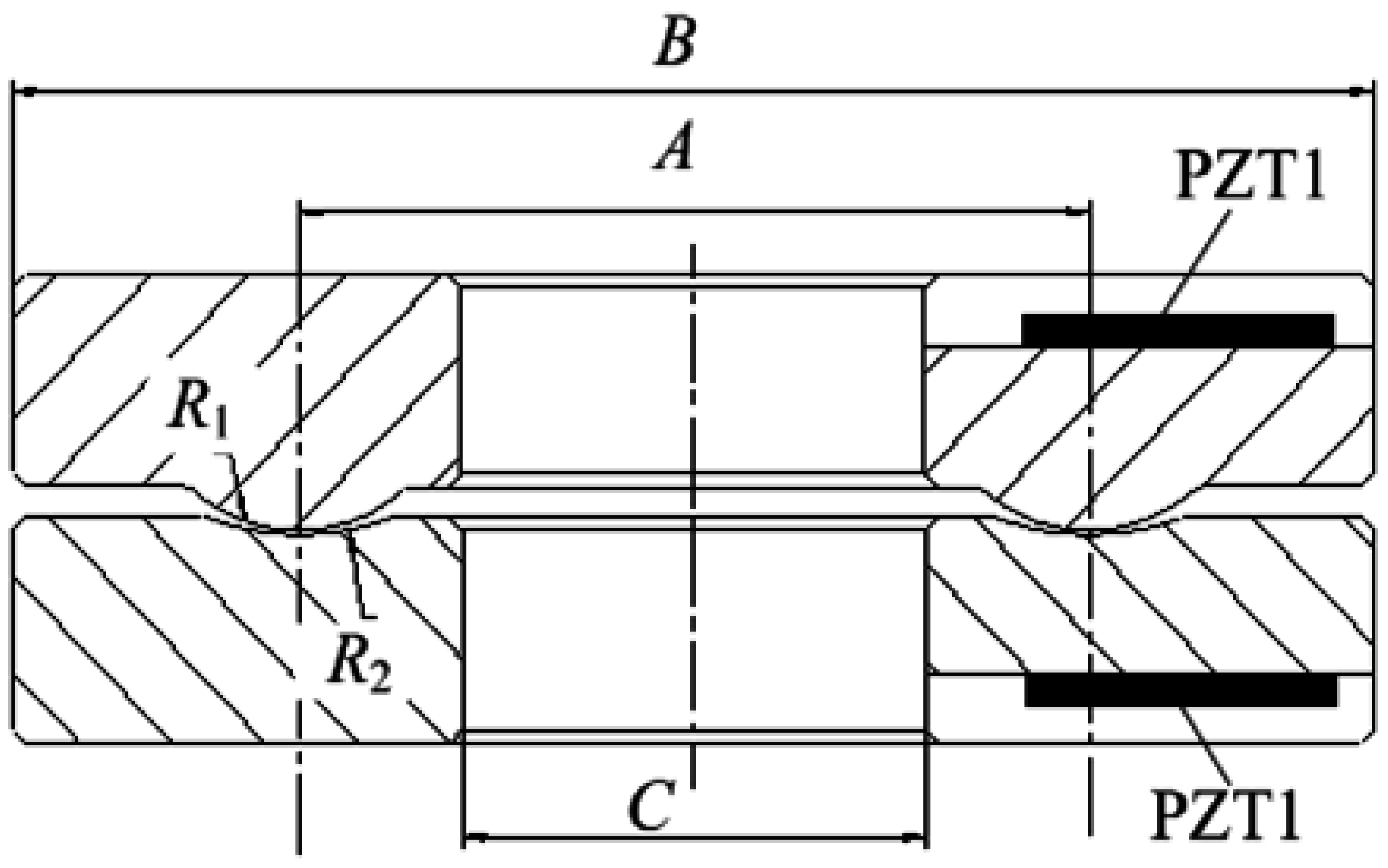
The size of the smart washer is designed based on the standard bolt M16, as shown in
Figure 4. The outer diameter of the washer is 50 mm and the internal diameter is 17 mm for the M16 bolt connection. The curvature of the convex
R1 and the concave
R2 are 6 mm and 10 mm, respectively. The detailed sizes of all specimens are listed in
Table 1. The above and bottom straight grooves, where the piezoelectric patches are placed, are filled with insulating glue to protect the piezoelectric patches. The piezoelectric constant d
33 and d
31 of the patch surface is 400 × 10
−12 CN and −150 × 10
−12 CN respectively, and the dimensions of the piezoelectric patch are 8 mm × 9 mm × 1 mm.
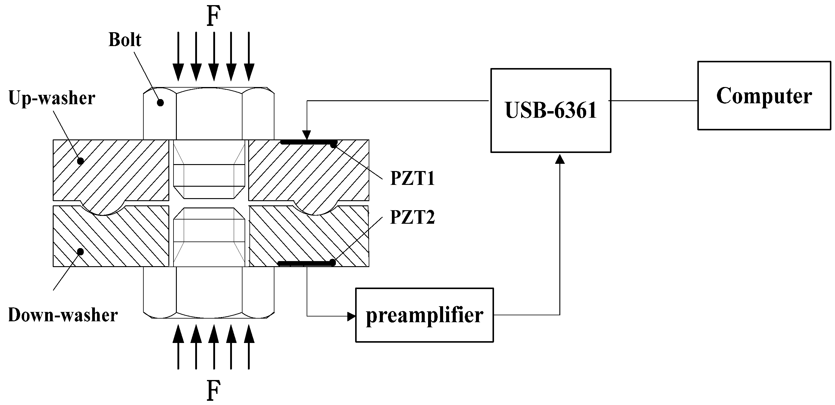
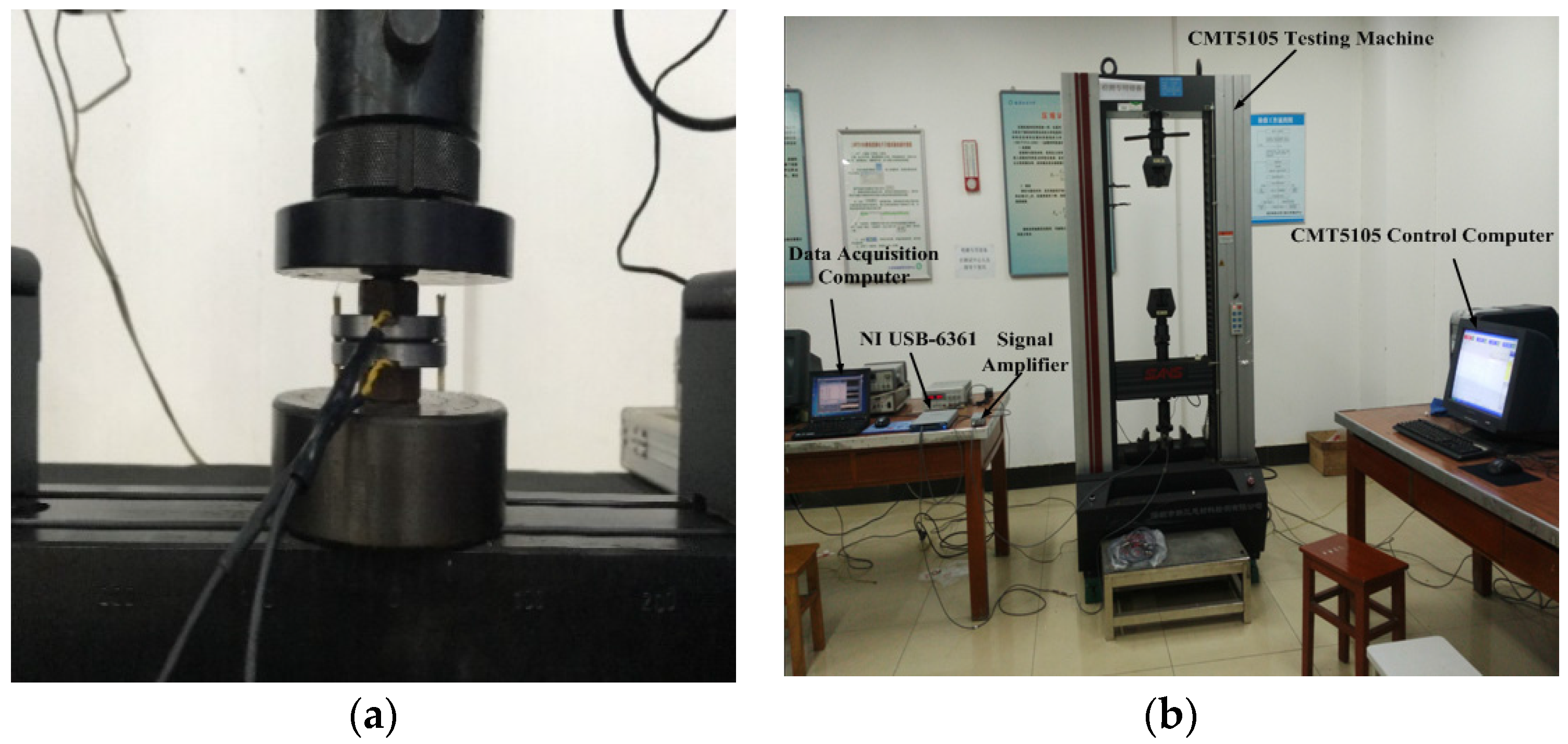
The purpose of the experiment is to verify whether the smart washer can effectively monitor the bolt looseness. The experimental scheme is shown in
Figure 5 and the experimental setup is shown in
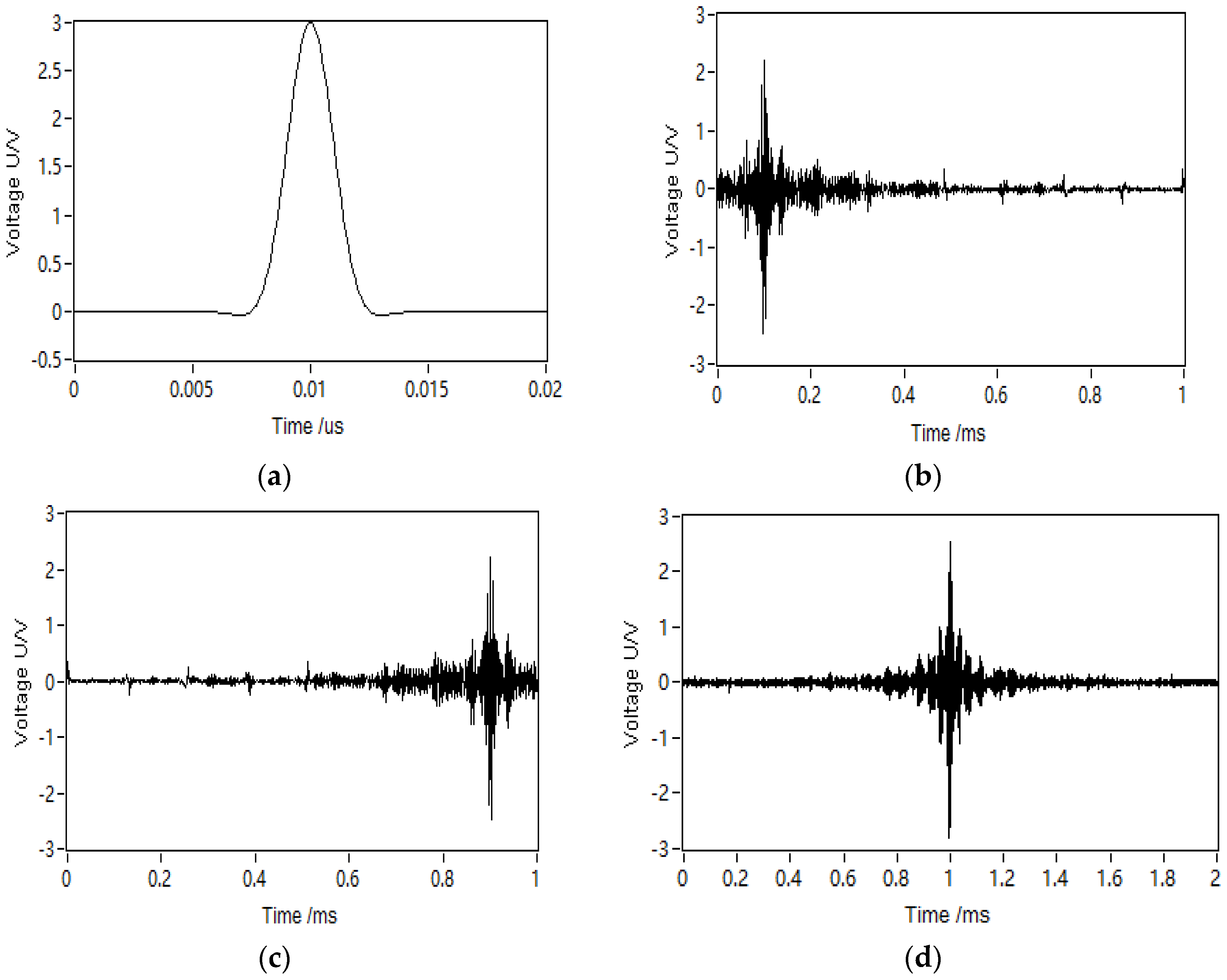
Figure 6 and an electronic universal testing machine (type CMT5105, SUNS, Shenzhen, China) was used to precisely simulate the bolt preload applied on the washer. In the experiment, the loading force ranged from 0 to 60,000 N to meet the rated load of grade 8.8 of M16 bolt. A National Instruments multifunction DAQ device, USB-6361(National Instruments Corporation, Austin, TX, USA), was used in the experiment as the data acquisition apparatus which converted between a digital signal and analog signal. For a given bolt load on a washer, a pulse excitation signal was launched by the LabVIEW in the computer as shown in
Figure 7a. The center frequency of the pulse signal was 150 kHz and the amplitude was 10 V. Then, the excitation signal was converted to an analog signal and is sent to excite the PZT1 by the NI USB-6361. The PZT1 generates an ultrasonic wave under the excitation of the pulse signal as shown in
Figure 7a, then the sensor PZT (PZT2) detected the response signal which was amplified by a signal amplifier (MISTRAS 2/4/6-C, PHYSICAL ACOUSTICS CORPORATION, Princeton, NJ, USA), as shown in
Figure 7b.
Figure 7c shows that the recorded response signal was reversed in the time domain which reemitted by the PZT1. The focused signal, as shown in
Figure 7d, is detected by PZT2 and was stored in the computer for further analysis. The procedure was repeated under different bolt preloads to obtain the focused signals at different bolt preloads, and the relationship between the focused signal peak amplitudes and the bolt preloads was then derived.
4. Experiment Results and Discussion
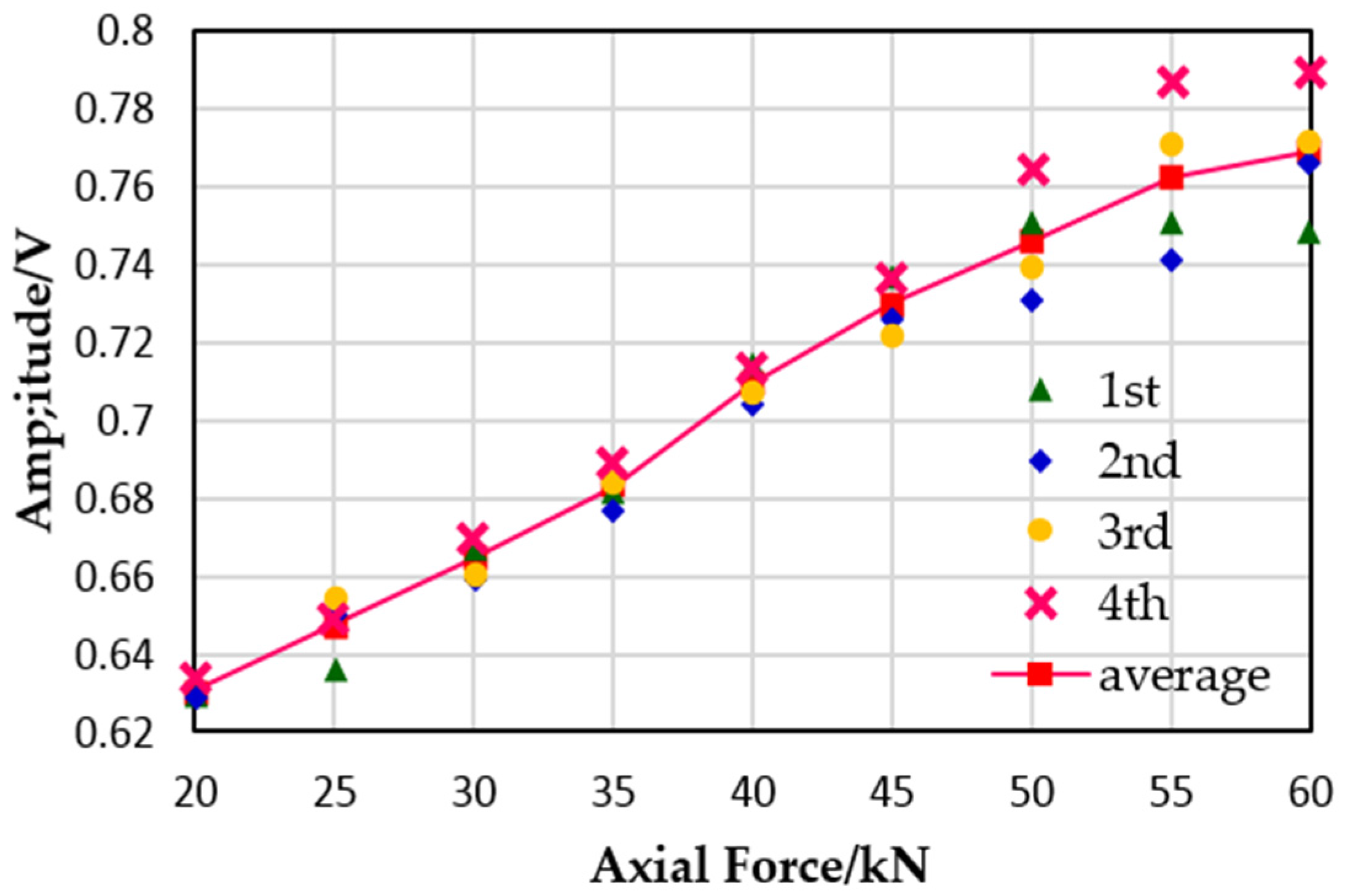
The experiments were carried out based on the above-mentioned procedure and the focused signals of two specimens under the same conditions were obtained. The relationship between the bolt preload and the peak of the focused signal extracted from the experimental data are shown in
Figure 8 and
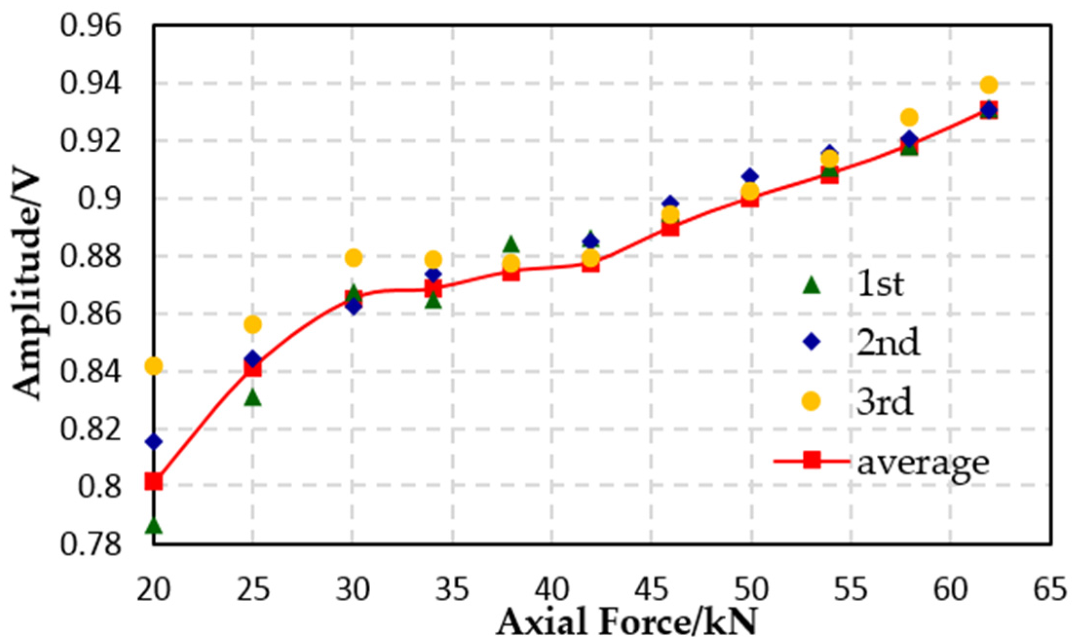
Figure 9. According to the relevant theory of bolt connection, only a very small part of the external load, which is applied on the bolt joint structure, works on the bolt when the bolt preload is enough, but once the bolt preload is insufficient, the external load that works on the bolt will be greatly increased and will most likely lead to the failure of the bolt. For the bolt joint structure, it is important to ensure that the bolt preload is at a reasonable level. Therefore, for the bolt preload monitoring, the prominent task is to monitor the axial force changes around its rated preload. Thus, it is unnecessary to monitor the force which is much smaller than the rated preload, and for this reason, the starting value of the abscissa is 20 KN in the experiments.
Figure 8 shows the experimental result of the first specimen with its center distance of the convex and concave being 25 mm from the washer center. It can be found that, with the increase of the bolt preload, the focused signal peak increases approximately linearly. This agrees with the analysis in
Section 2 which shows that the peak amplitude increases with the increase of the axial force. The slope of the curve is steep enough to interrogate the change of the bolt axial force. Even at the 60 KN preload, the focused signal peak still kept increasing, thus the designed smart washer can monitor the full range of the M16 bolt. The effectiveness of the proposed design is validated by this experiment.
Figure 9 shows the result of specimen 2 (the center distance is 29 mm); the focused signal peak amplitude keeps increasing and does not reach saturation. Nevertheless, the curve has gently changed between 30 and 40 kN, which may be caused by the machining errors of the specimen.
The experimental results show that the amplitude of the focused signal can indicate the bolt preload obviously, that is to say that the smart washers, based on the piezoelectric active sensing method and time reversal technique, can effectively monitor the bolt looseness in the related preload range. By comparing the experimental results of the two specimens, it is shown that a small change in the contact location will not obviously affect the contact area change under the applied preload range and thus will not affect the transmitted wave energy change. For the M16 bolt, the designed smart washer is sufficient to measure 20 kN~60 kN axial force which covers the rated preload range of the bolt, and the change of amplitude with obvious axial force. Hence, for the different types of bolt, by designing a washer that is different in size, the entire rated preload measurement of the bolt can be fulfilled successfully.
5. Conclusions
As previously stated, a smart washer based on the piezoelectric active sensing method was proposed for bolt looseness monitoring. The applicability and effectiveness of the smart washer has been presented by experimental studies. Based on the theory that the change of the transmitted wave energy, through a bolted joint interface, depends on the bolt preload force, the bolt loosening status can be deduced by observing the change of the peak amplitude of focused signals. The experiment results show that the focused signal peak amplitude has an approximate linear correlation with the bolt preload.
Further researches are needed to design the different curvature radii of the convex and concave surfaces and to determine the sizes of the smart washer, in order to form a series of smart washers that can measure the full range of the rated preload of different types of bolts. Lastly, through theoretical analysis and numerical simulation, the smart washer structure can be optimized.


