1. Introduction
To address energy scarcity and environmental pollution, many countries have issued and implemented strict standards of vehicle energy consumption and automotive exhaust emissions. Although new energy vehicles (NEV) can effectively meet these standards, replacing the internal combustion engine (ICE) vehicle with NEV is difficult because of technical issues, such as small battery capacity, long charging time, and high battery cost. The automotive industry is striving to improve the efficiency of the energy management technology for ICE vehicles to ensure better fuel economy and less harmful exhaust emissions [
1].
Today, the online energy management method has become an important research direction to improve vehicle fuel economy. An energy management strategy for plug-in hybrid electric vehicles (PHEV) was proposed by Zheng [
2], which used Pontryagin’s minimum principle (PMP) to split power. Hanane [
3] predicted the future power demand of vehicle through a Markov chain model and then calculated power distribution between the supercapacitor and fuel cell through PMP. Similarly, Hou [
4] presented an optimal energy management strategy based on an approximate PMP algorithm for PHEVs. An adaptive supervisory controller was proposed by Simona [
5] based on PMP for the online energy management optimization of PHEV. For the implementation of an energy management strategy, Zou [
6] concluded that PMP computation time is significantly less than that of dynamic programming under the same conditions.
Although the aforementioned methods can improve fuel economy effectively, they cannot directly extend to ICE vehicles because of distinctively different structures of vehicle electrical systems. The power system of ICE vehicles is composed of an alternator and a battery. An intelligent control strategy of a vehicular alternator was observed in the studies by Kong [
7]. The strategy reduced fuel consumption by adjusting the working mode of the alternator. Yang [
8] investigated the methods of battery management that partitions the working states of the battery and monitor. However, previous studies concentrated less on the collaborative work between the alternator and the battery. Colin [
9] and Jeremy [
10] presented a model-based supervisory energy management strategy, respectively. The strategy attempted to control the duty cycle of the alternator to meet the instantaneous demand of load current. However, the strategy seems to be difficult to implement in engineering. For ICE vehicles, a vehicular energy management system based on local interconnection network (LIN) bus was proposed by Wang [
11], in which a double fuzzy controller was designed to recover braking energy. However, the controller only controlled the output of the alternator according to the vehicle speed and the state of the battery charge, and it never considered the variation of the electrical load.
Based on previous studies, a bus-based real-time energy management system is proposed for the ICE vehicle electrical system, and its real-time energy management strategy based on PMP is presented. The proposed strategy optimally distributes the power demand of electrical load between the intelligent alternator and the battery so that better fuel economy can be obtained.
The remainder of this paper is organized as follows:
Section 2 describes the bus-based power management system, and the vehicular electrical system is modeled through experiments in
Section 3; the real-time energy management strategy for the power management system is proposed in
Section 4, and
Section 5 discusses the experimental results; finally, conclusions are provided in
Section 6.
2. Bus-Based Energy Management System
2.1. Structure of the System
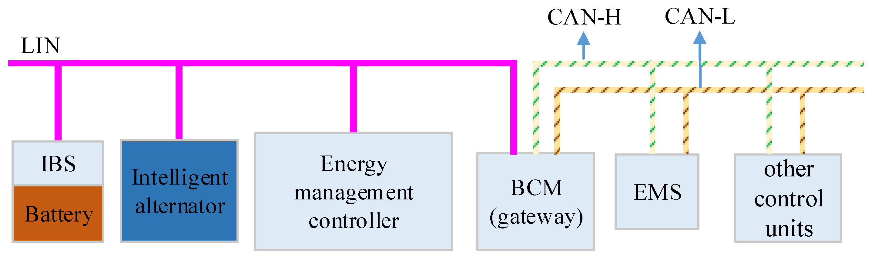
An energy management system is considered, as shown in
Figure 1. This system consists of an energy management controller (Jianghuai Auto., Hefei, China), an intelligent battery sensor (IBS, Hella, Lippstadt, Germany), and an intelligent alternator (Bosch, Stuttgart, Germany), which communicate with each other through the LIN bus. The body controller module (BCM), engine management system (EMS), and other control units, such as the controller for the air conditioning, are located in the controller area network (CAN). Various control signals between the LIN and CAN buses are transferred by the gateway BCM.
The intelligent alternator is the main power source, and the battery is the auxiliary power source, in vehicles. The IBS collects the voltage and current, and calculates the state of charge (SoC) of the battery in real-time. The BCM sends the on-off state of electrical loads, while the EMS provides the vehicle and engine speed, and engine torque. When the energy management controller receives the aforementioned information, it will optimize the distribution of the alternator output power and battery output power to maintain the best fuel consumption.
2.2. The Battery SoC and Intelligent Alternator Operation Mode
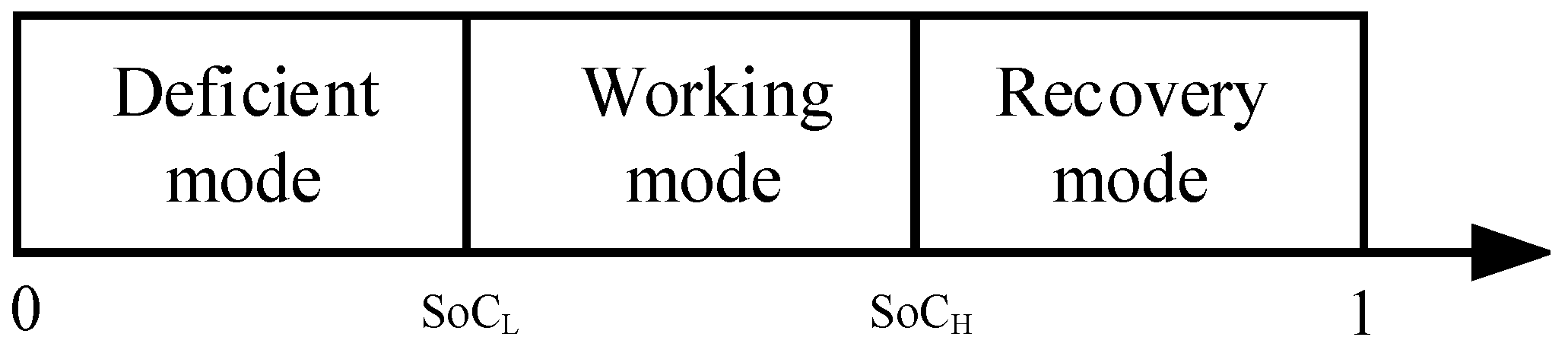
The battery charge level is divided into three modes: deficient, working, and recovery [
8]. When the battery SoC is in the deficient mode, the battery should be charged quickly. When the battery SoC is in the working or recovery modes, the charging and discharging of the battery should be controlled according to driving situations and the total power demand of the electrical loads. The recovery mode is considered to provide sufficient capacity for braking energy recovery. All battery modes are shown in
Figure 2.
The intelligent alternator has four operation modes, as shown in
Figure 3. These modes are ready, pre-excitation, voltage regulation, and excitation off. The ready mode is activated only when the sleep command is received from the energy management controller, and the rotational speed of the alternator
nG does not exceed the rotational speed threshold
n0. The alternator switches into pre-excitation mode if a valid set voltage U
S is more than the voltage threshold U
0 and
nG <
n0. For the pre-excitation mode, if
nG exceeds
n0, the voltage regulation state is entered, and the output voltage of alternator can be regulated. Without an activation command, and if the rotational speed of the alternator
nG exceeds the rotational speed
n1 (
n1 >
n0), the alternator switches into the voltage regulation state directly. When the command of excitation off from the energy management controller is received, the alternator stops the excitation until a valid new set voltage U
S is received.
When more electrical loads are switched on, and the SoC of battery is in the recovery mode, the energy management controller reduces the alternator voltage or closes its excitation and makes the battery work for the electrical loads to maintain a low level of engine fuel consumption. When the battery SoC is in the working or recovery modes, the higher voltage of the alternator is regulated by the energy management controller to recover the braking energy. When the battery SoC is in the deficient mode, the energy management controller raises the charging voltage of the battery, so the battery SoC can return to the working mode quickly.
4. Real-Time Energy Management Strategy
4.1. Problem Description
The energy management of the vehicle electrical system is a type of optimization problem with boundary conditions in a specific driving cycle. For the optimal fuel economy, the energy management strategy of the vehicle electrical system aims to control the output power of the battery and the alternator, and to maintain the battery SoC within the working mode.
Therefore, the energy management strategy can be simplified as the control of single degree of freedom. The system controlled variable
u(
t) is the battery power
PB(
t), the system state variable
x(
t) is the battery SoC, and the control objective is to minimize fuel consumption of the engine. Accordingly, the objective function of the energy management strategy under a driving cycle in the duration [
t0,
tf] is expressed as follows [
15]:
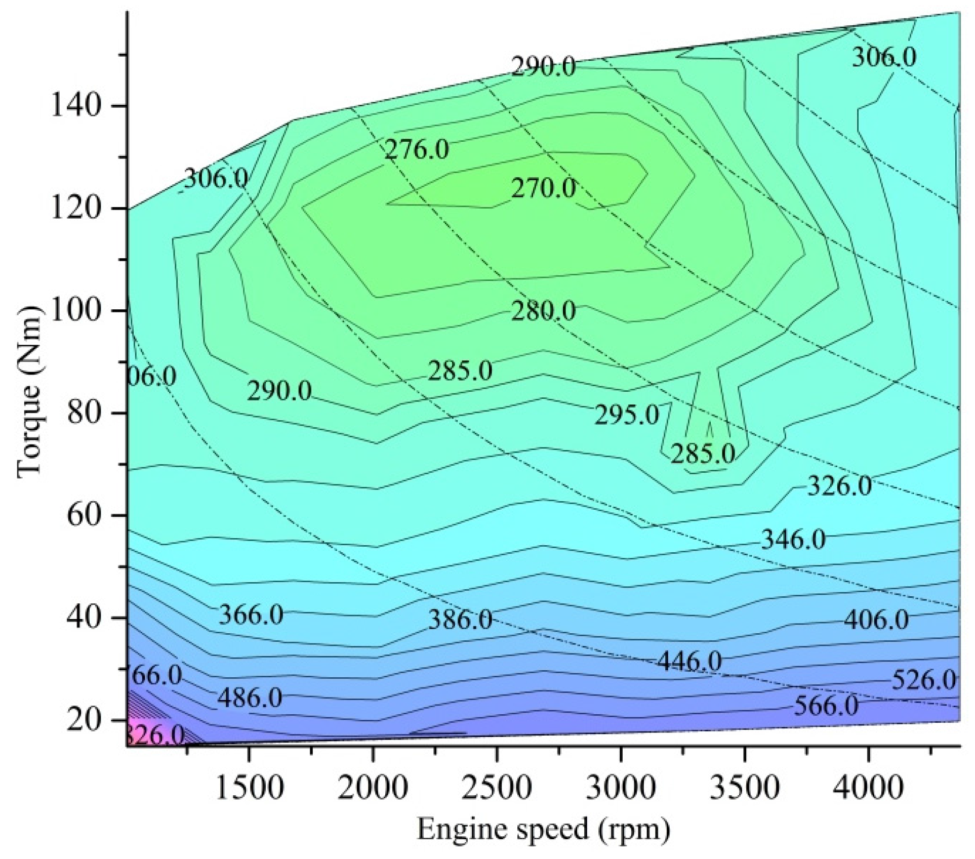
where
is the fuel consumption rate of the engine, and its value can be obtained from the characteristic curve of engine mapping in
Figure 5 based on the rotational speed
n of the engine and torque
T.
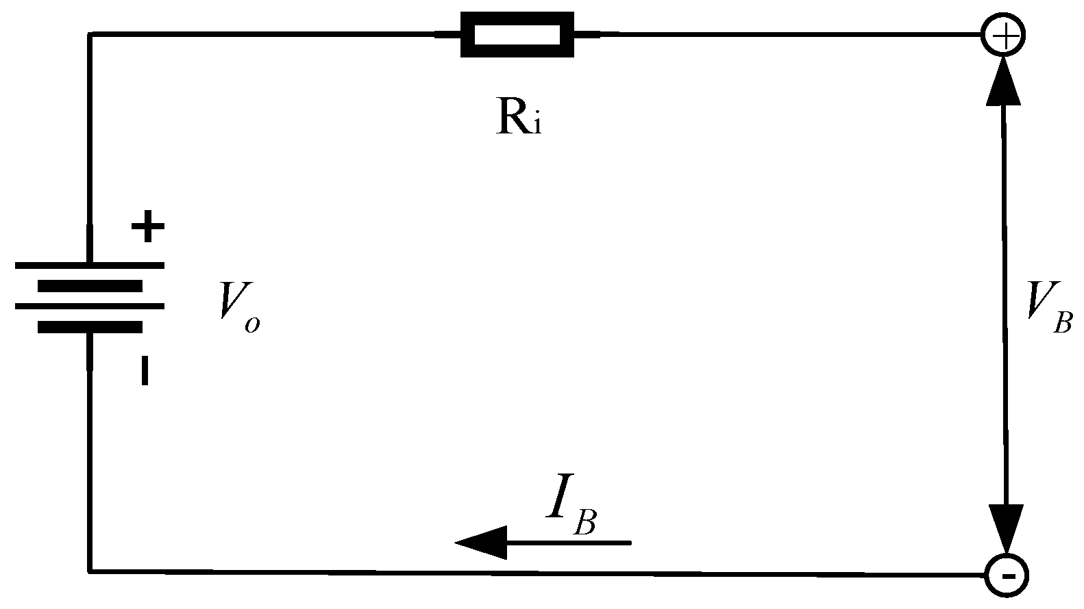
To simplify the study, if we neglect the time-variant parameters of the battery, such as ohmic resistance and polarization resistance, the system state equation can be derived according to Equations (2) and (3), as follows:
where
PB(
t) expresses the charging and discharging power of the battery at
t moment, and
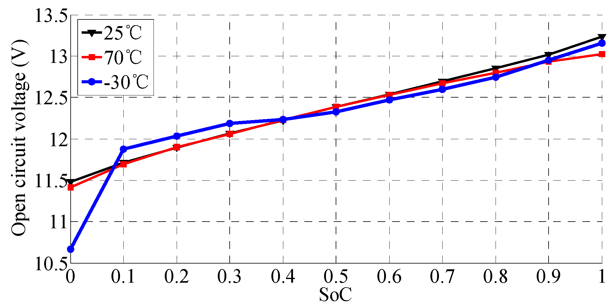
Vo(
x) is OCV when SoC is
x.
To avoid overcharging and overdischarging of the battery, the final and initial values of SoC are generally required to be equal, and the battery constantly works within a certain range. In addition, the output power should meet certain constrained conditions when controlled by the working capacity of the alternator and battery:
where
xmin and
xmax are, respectively, the upper and lower limits of the battery SoC.
PL is the power of thre electrical load;
Pmax is the maximum output power of the alternator; and
PB_min and
PB_max are the maximum charging power and maximum discharging power of the battery, respectively.
4.2. PMP-Based Solution
According to the aforementioned objective function, PMP can convert the global optimum problem into a local one by a series of constrained conditions. The following Hamiltonian function [
15] expresses the objective function in Equation (8):
In Equation (8), γ(
t) is the co-state and ϕ(
t) is the working mode coefficient of the battery. The specific expression is listed as follows:
where
SoCH is the upper limit of SoC, and
SoCL is the lower limit of SoC for the battery working mode; the working mode coefficient of the battery ϕ(
t) is set to limit SoC within the working mode.
The power distribution for the minimum fuel consumption rate based on PMP should meet the following conditions [
16,
17]:
At the duration [t0, tf] of a driving cycle, an optimal control variable exists, which enables the Hamiltonian function H(x*, u*, γ*, ϕ*, t) to be a global optimal solution.
Meanwhile,
x*(
t) and γ*(
t) should satisfy the following canonical equations:
Therefore, H(x*, u*, γ*, ϕ*, t) = min H[x, u, γ, ϕ, t] and . The optimal control variable is u* = arg min H[x, u, γ, ϕ, t], and the desired u* is the optimal power distributed by the battery. Hence, the alternator power should be the difference between the load power and the battery power.
4.3. Acquisition of the Co-State γ(t)
According to Equation (8), γ(
t) is the penalty factor of the SoC change rate, and the changes of γ(
t) affect the SoC changes. The constrained conditions of Equation (7) indicate that the acquisition of γ(
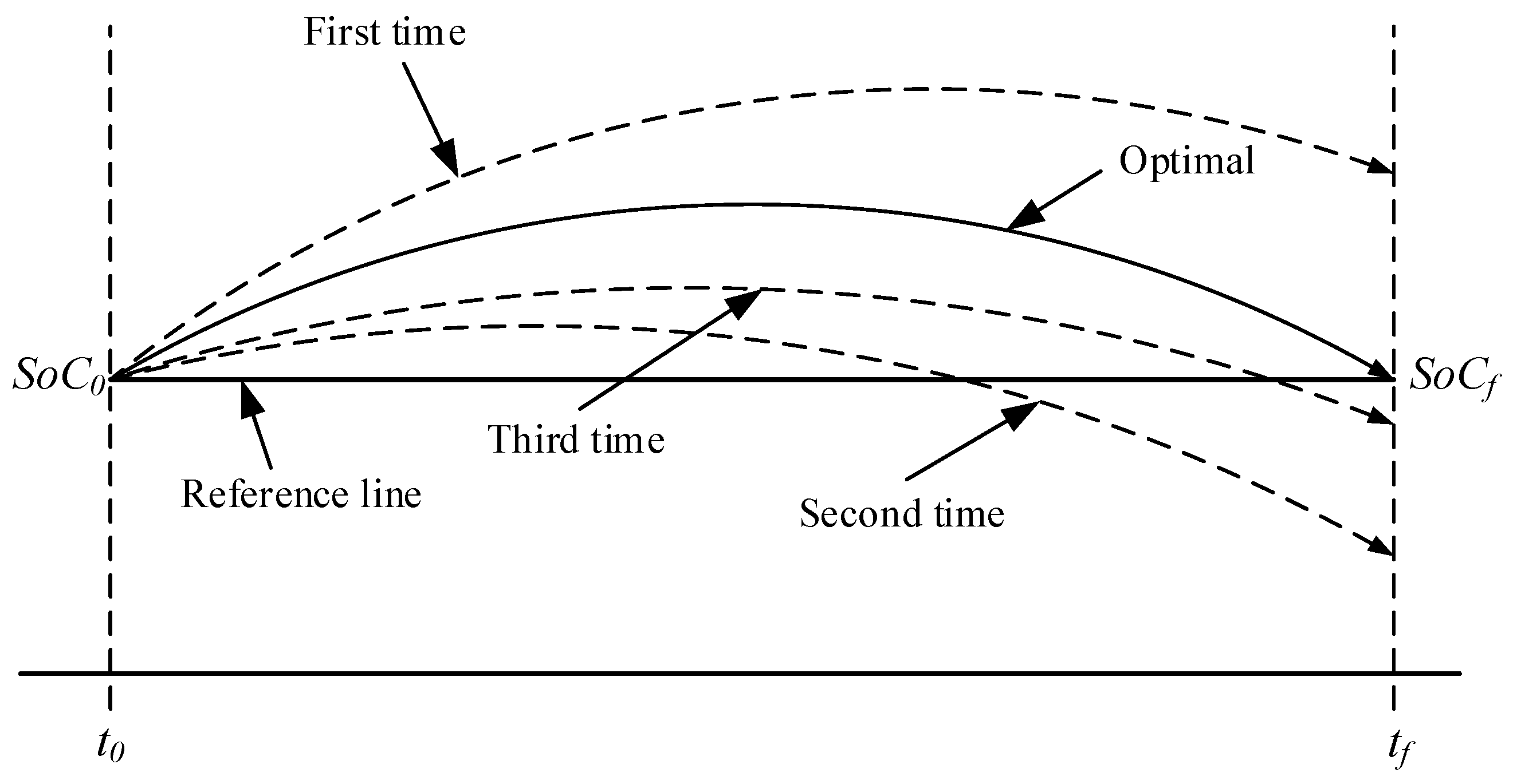
t) is a problem of two-point boundary values. Generally, the shooting method is used to solve the problem by converting it into an initial value problem [
18]. In this method, the initial co-state of γ(
t), i.e., γ
0, can be determined by repeatedly trying until the final states satisfy the boundary condition, as shown in
Figure 8. If the initial state
SoC0 is known, and
γ0 is set as a value, then the final state
SoCf is obtained by solving differential Equation (5). If
SoC0 is not equal to
SoC0, then γ
0 is updated and the process is repeated until
SoCf =
SoC0.
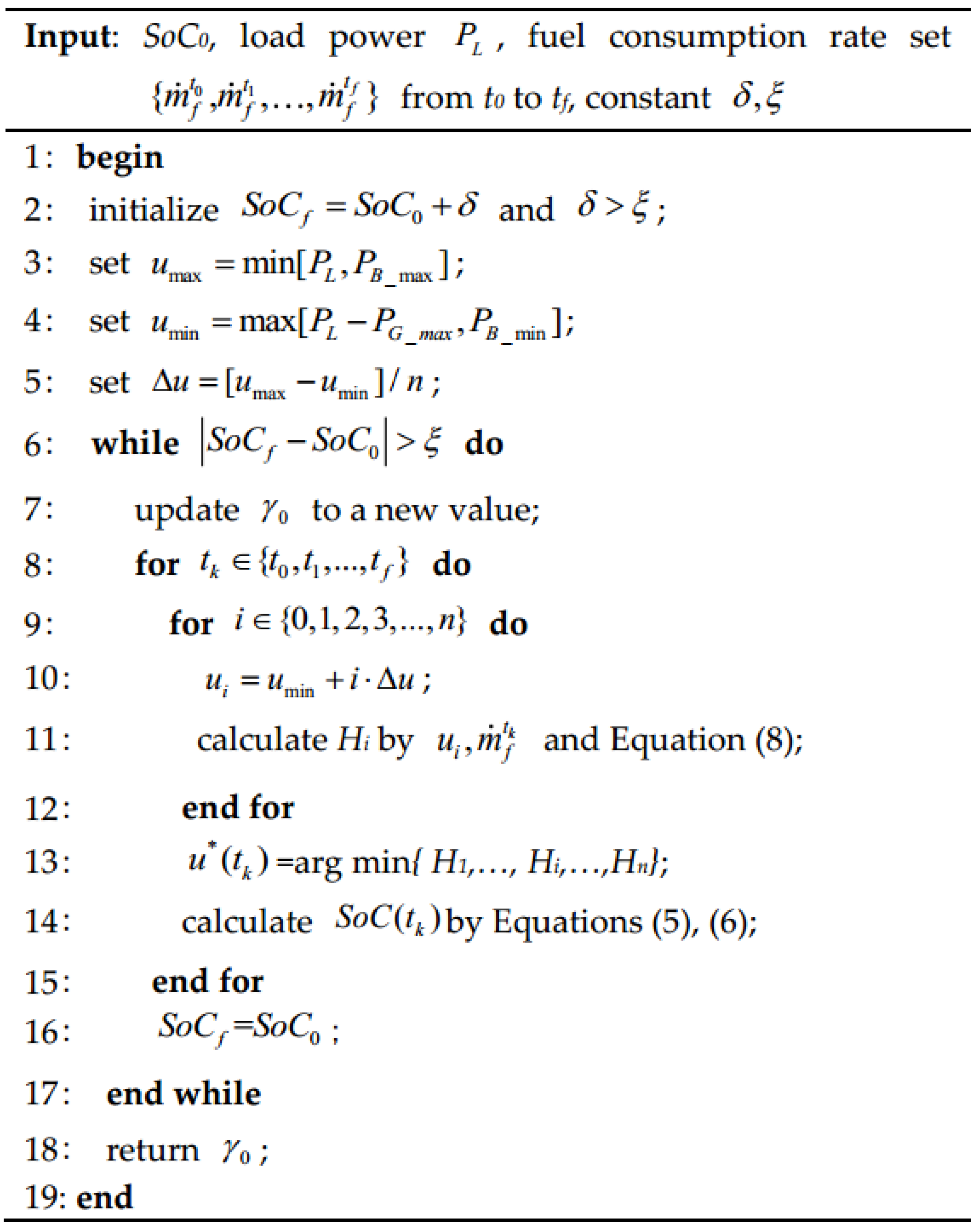
For a specific driving cycle, if the load power change is known, γ
0 can be calculated offline by using the given shooting method. An algorithm to calculate γ
0 offline corresponding to a particular load power is presented in
Figure 9. The algorithm inputs are
SoC0, load power
PL, fuel consumption rate set in the time [
t0,
tf] of the given driving cycle, and calculation constants δ and ξ. The main process of the algorithm is detailed as follows:
The upper and lower limits of u are set according to PL: and .
Set ∆u = [umax − umin]/n and discretize as ui = umin + i·∆u, i = 0, 1, 2, …, n.
For a given γ0, calculate the Hamiltonian function Hi for each ui at tk by Equation (8).
Select u*(tk) = arg min{H1,…, Hi,…, Hn} and calculate the current SoC(tk).
Repeat steps (1)–(4) until the driving cycle is over, i.e., tk = tf.
Check whether |SoCf − SoC0| > ξ. If it is false, return the current γ0; otherwise, update γ0 and repeat steps (1)–(6) until a valid γ0 is obtained.
4.4. Strategy Implementation in Energy Management Controller
According to the real scenarios of electrical load use, the requirements of load powers in a vehicle can be divided into several grades, which are denoted as the load power set
. For
, the algorithm in
Figure 9 can be used to find its corresponding initial co-state
if the driving cycle is given. Set
is the initial co-state set, which corresponds to
P.
P and
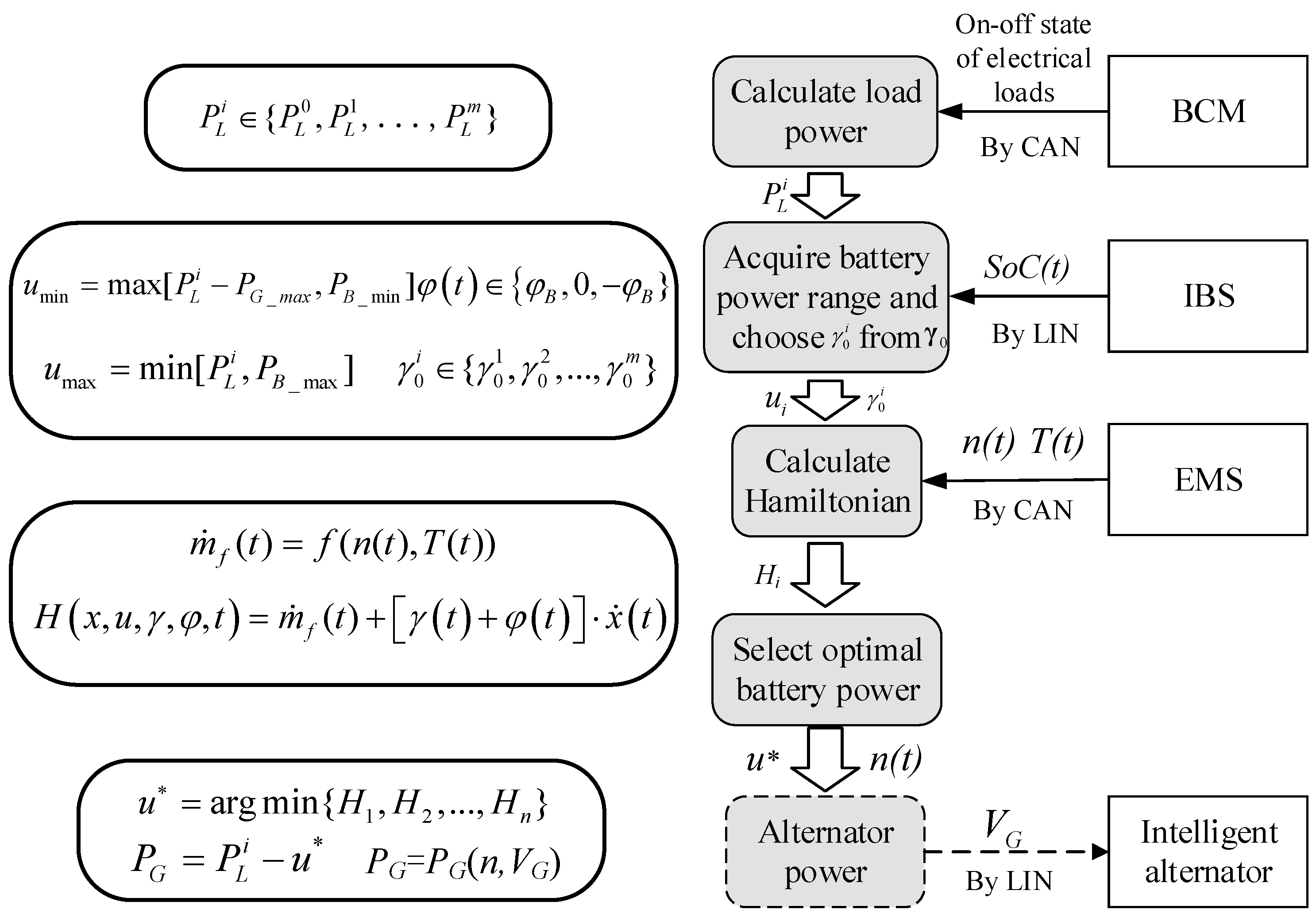
γ0 are used to implement the aforementioned strategy in an energy management controller. The working process of the strategy is shown in
Figure 10.
In
Figure 10, the BCM monitors the working state of electrical loads in the vehicle, and the SoC(t) of the battery is measured by the IBS in real-time. The EMS collects the rotational speed
n(t) and torque
T(t) of the engine, which are used to calculate the fuel consumption rate
. First, the energy management controller calculates the current requirements of load power
based on the information from BCM and finds the corresponding initial co-state
in
γ0. Next, the Hamiltonian function
Hi corresponding to each
is calculated through SoC
(t),
, and
. Then, the desired output power of the battery is chosen as
u*, which makes the Hamiltonian function
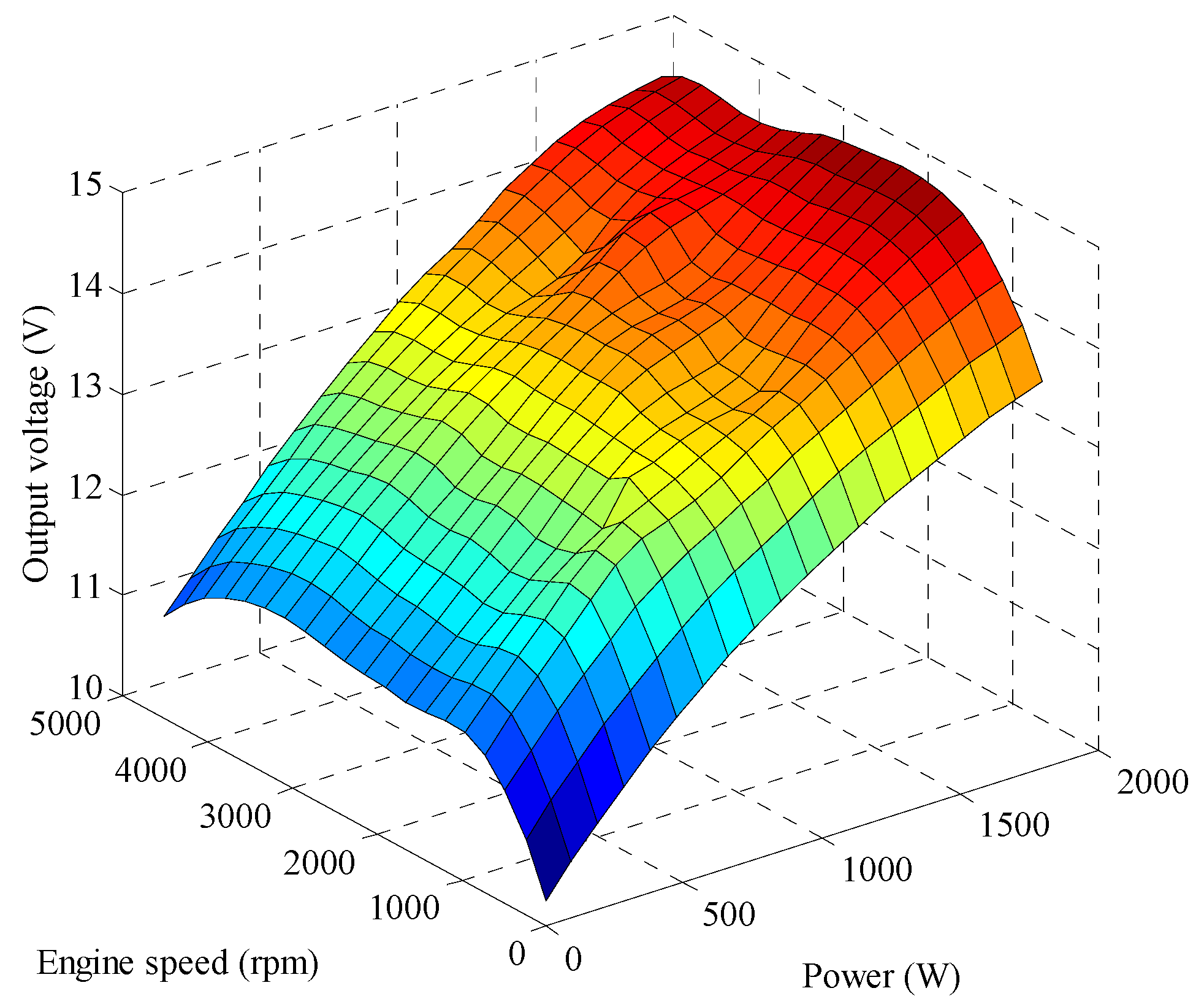
Hi the minimum. Therefore, the desired output power of the alternator is obtained as
. Finally, this output power of the alternator is converted into the control signal of the voltage based on the model in
Figure 4, and the control signal is sent to the intelligent alternator to adjust its output power.
5. Experimental Results and Analysis
To validate the proposed method in this paper, different experiments are conducted on the vehicle platform, which is shown in
Figure 11. The vehicle platform consists of chassis dynamometer, experimental passenger vehicle, and related instruments. The passenger vehicle is equipped with the proposed energy management controller, the IBS, which is designed by Hella (Lippstadt, Germany). The intelligent alternator is developed by Bosch (Stuttgart, Germany). Two current sensors and two voltage sensors are employed to measure the current and voltage of the battery and the intelligent alternator. These real-time data are collected by DAQ devices from National Instruments (Texas, TX, USA), and Vector CANoe (Vector, Stuttgart, Germany) is used to monitor the information in CAN and LIN buses.
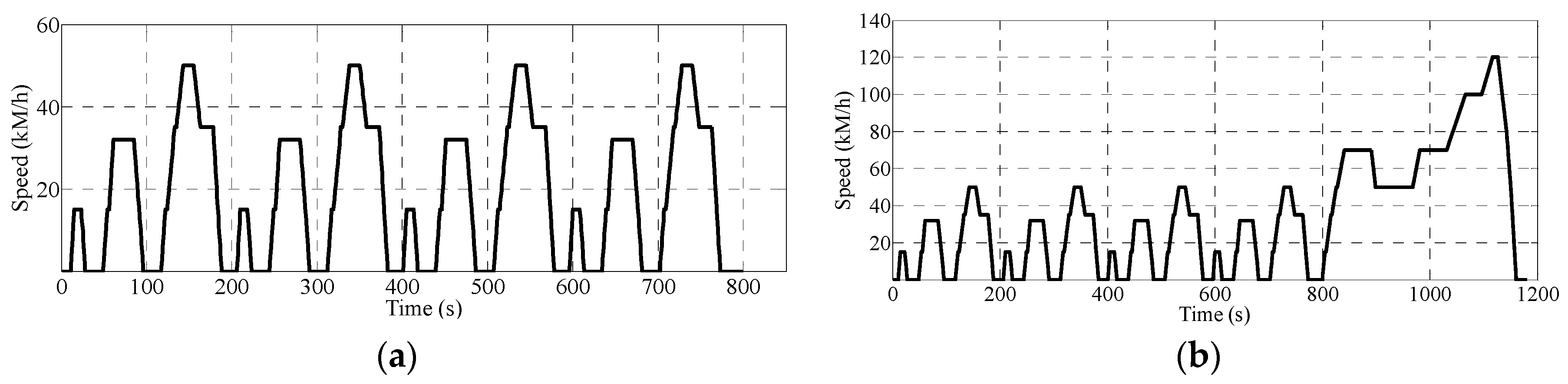
Two driving cycles are applied for the experiments on the platform. The Economic Commission for Europe (ECE15) [
9] and New European Driving Cycle (NEDC) [
11] are shown in and
Figure 12. Under ECE15, the experiment is carried out with constant electrical load power. The other experiment is carried out with changing load power under the NEDC.
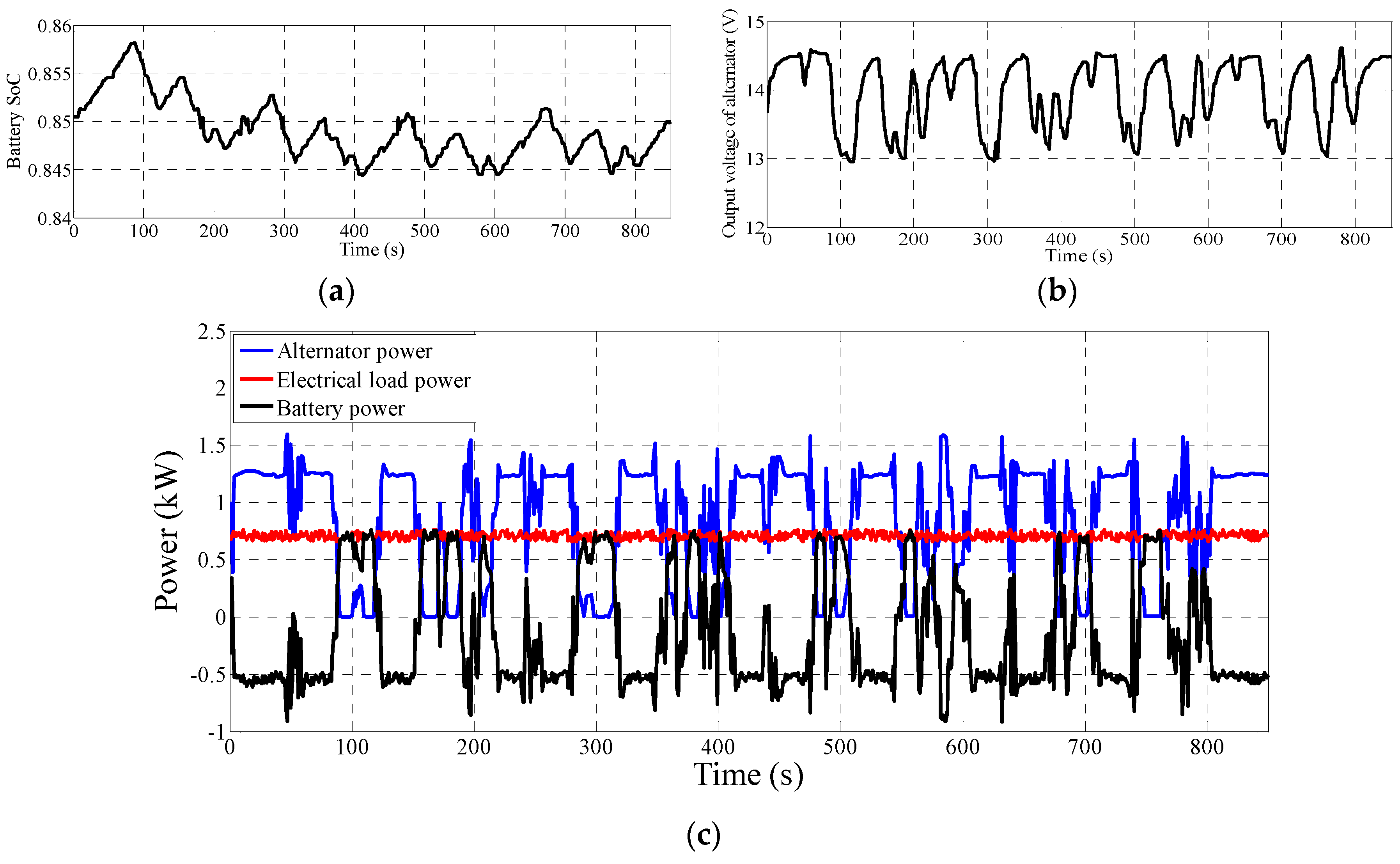
5.1. Experiment with Constant Electrical Load Power
Under the ECE15, the experiment with constant electrical load power is conducted. When load power is 0.7 kW, the initial co-state with the shooting method is γ*(t) = −58. When ΔSoC = 0, the solution is optimal when γ(t) satisfies all of the constrained conditions of PMP, including the constraint of Equation (7) on battery SoC.
Figure 13 presents the experiment results, which indicates that the energy management strategy of optimal power distribution (OPD) limits the SoC fluctuation of the battery. The final state differs slightly from the initial state and meets Equation (7). When the vehicle speeds up, the intelligent alternator decreases the output voltage, and the battery becomes the primary power supply and results in an effective increase of vehicle dynamic performance; when the vehicle slows down, the intelligent alternator increases output power, and the battery is charged rapidly to recycle and store kinetic energy into the battery.
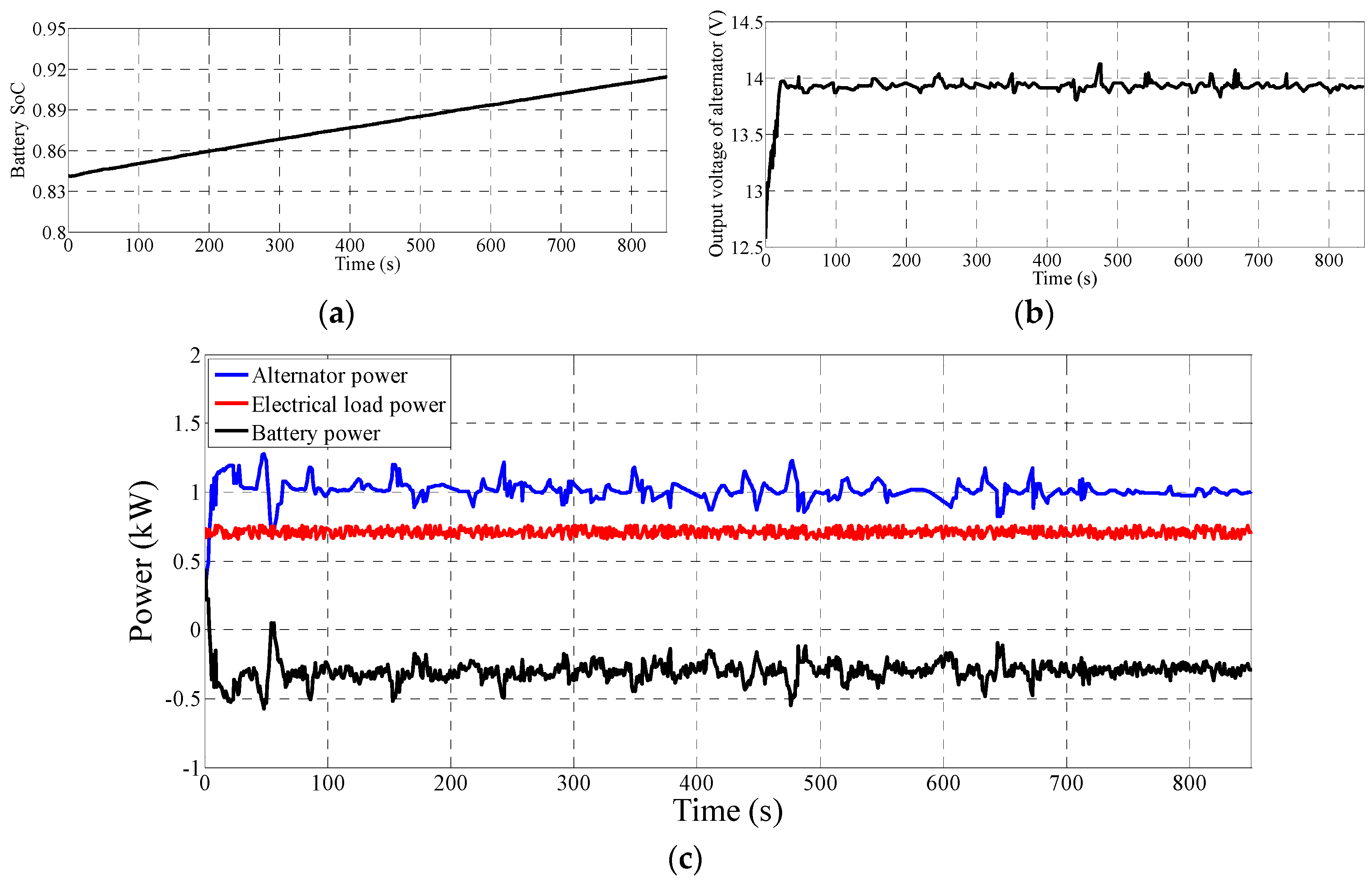
To verify the OPD strategy, the same experiment is conducted in the vehicle without an energy management system, which is called the open-loop control (OLC) strategy.
Figure 14 indicates that the battery is being charged often in the OLC strategy. The battery power being charged is approximately 0.3 kW, while the alternator power is around 1 kW, which is exactly the sum of the electrical load power and the battery charge power.
A comparison of the output voltages in
Figure 13 and
Figure 14 show that the OPD strategy causes the alternator voltage to fluctuate fiercely, while the OLC strategy maintains the voltage stability at around 14 V. The alternator power is adjusted by a voltage change to reduce fuel consumption. This condition also improves the utilization efficiency caused by repeatedly charging and discharging the battery. The comparison of fuel consumption of OPD and OLC is presented in
Table 1. For 100 km, OPD consumes 0.15 L fuel less than OLC, and the fuel saving rate is approximately 1.9%.
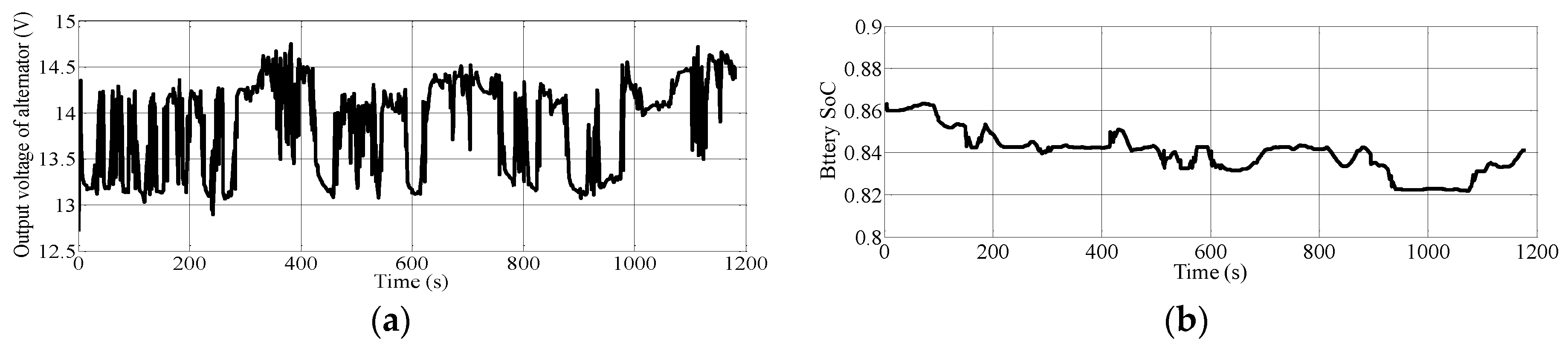
5.2. Experiment with Changing Load Power
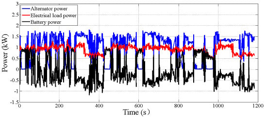
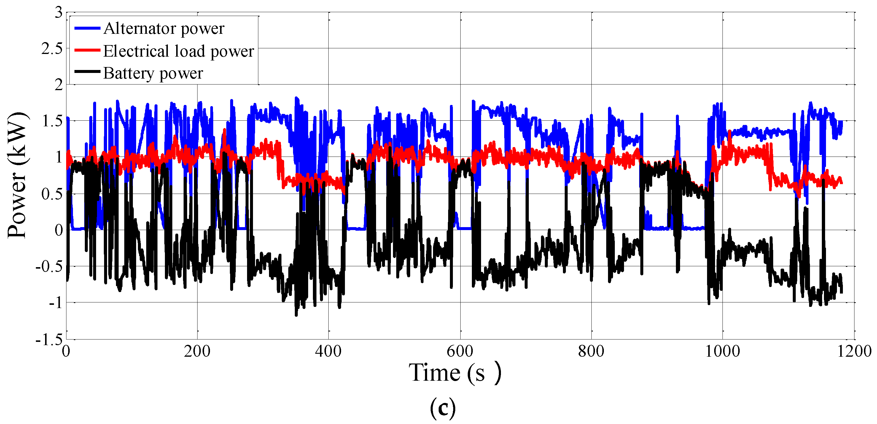
Under the NEDC, an experiment with changing load power is conducted.
Figure 15 shows the power curves of the battery, alternator, electrical load, and output voltage curve of the alternator. The experiment results are similar to those of the experiment with unchanged load power. For the change of vehicle electrical appliances, the output voltage of the alternator is maintained between 13 V and 14.8 V; the battery SoC can fluctuate within a certain range; and the final SoC is almost equal to the initial SoC. However, the total output power from the battery and alternator is almost equal to the load power. This condition denotes that the energy management controller with the OPD strategy can distribute the demand of load power in real-time to the battery and the alternator, thereby decreasing the fuel consumption from the alternator.
Table 2 presents a comparison of the fuel consumption of OPD and OLC under the NEDC. For 100 km, OPD consumes 0.14 L fuel less than OLC, and the fuel saving rate is about 1.7%. All of the results demonstrate that the OPD strategy can effectively reduce vehicle fuel consumption and increase vehicle fuel economy.
Furthermore,
Table 3 lists the improved effects of fuel economy from the A-PMP (Adaptive PMP) strategy in [
9] and the OPD strategy in this paper. The A-PMP strategy in [
9] can increase fuel economy by almost 1.4% while the OPD strategy in this paper can increase fuel economy by almost 1.7%. The improvement of fuel economy from the A-PMP and the OPD is very close. However, the implementation of A-PMP relies on modifying the structure of the alternator controller. It is much more complicated than the implementation of OPD based on an intelligent alternator. Therefore, OPD is superior to A-PMP on the implementation and engineering application.
6. Conclusions
For the electrical system of ICE vehicles, an energy management system is investigated, and a real-time control strategy of the energy management in this system is proposed. The control strategy can appropriately distribute output power of the intelligent alternator and battery power according to the electrical load and driving cycle. The experimental results demonstrate that, compared with the widely-applied OLC strategy, the proposed OPD strategy leads to improved fuel economy. In the future, the electrical model of the vehicle power supply system will be studied in depth, with emphasis on methods to reduce the calculation complexity of the OPD strategy. This type of research will help accelerate the practical application of the energy management system in ICE vehicles.


