
Transferring Pressure Mechanism Across Gob-Side Roadway Goaf with Coal Pillar During Distant Face Mining: A Case Study

 , ,
, ,
Abstract
1. Introduction
2. Engineering Overview
2.1. Basic Conditions of Roadway
2.2. Roadway Maintenance Effect
2.3. Analysis of Cause of Deformation and Instability of Surrounding Rock of Roadway
3. Occurrence Mechanism of Transferring Pressure Across Goaf of Alternative Wide and Narrow Working Faces
3.1. Principle of Transferring Pressure Across Goaf Effect of Alternative Mining of Wide and Narrow Working Faces
3.2. Analysis of Disturbance Mechanism of Transferring Pressure Across Goaf Effect to Gob-Side Roadway
4. Simulation Verification of Transferring Pressure Across Goaf Effect
4.1. Model Establishment and Simulation Method
4.1.1. Model Establishment
4.1.2. Simulation Method
4.2. Arrangement of Monitoring Points
4.2.1. Arrangement of Monitoring Points for Vertical Displacement of KS in Overlying Strata
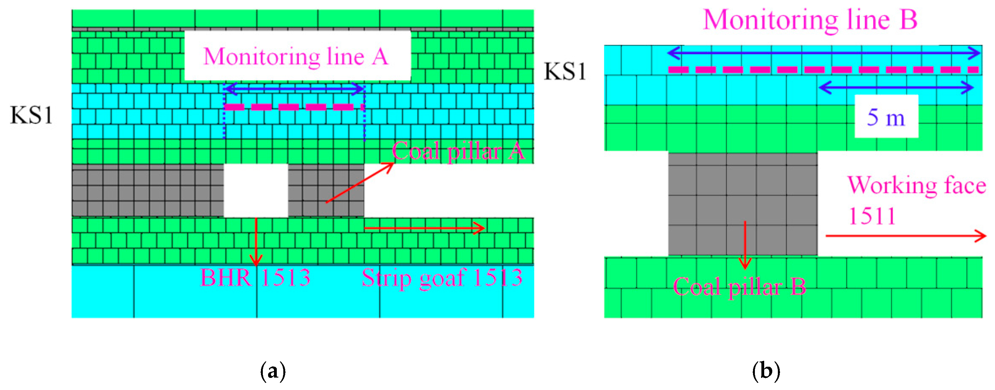
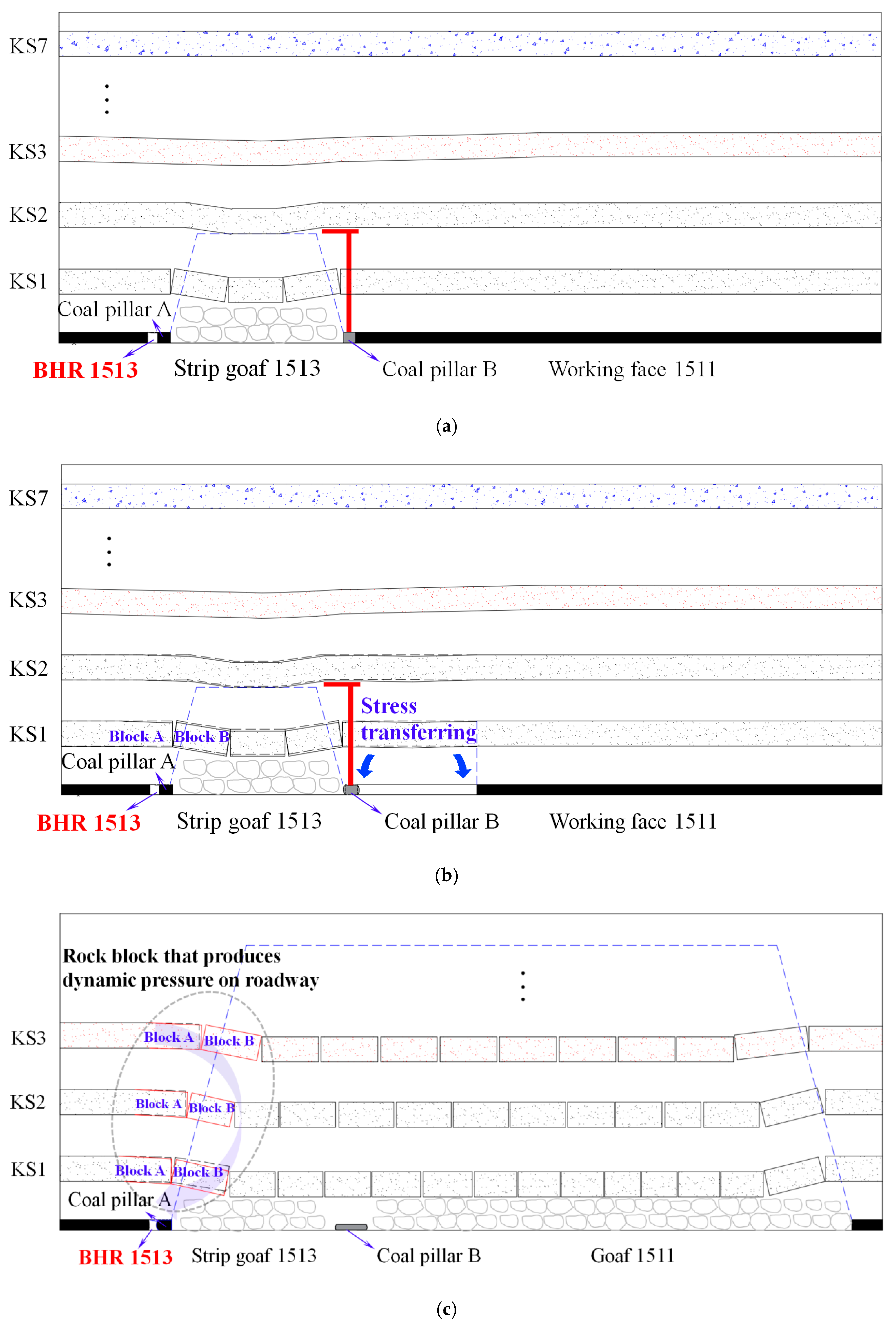
- For the comprehensive assessment of overburden behavior adjacent to BHR 1513, seven vertical displacement monitoring lines (designated as Line A) were installed—one for each key stratum (KS1–KS7). These measurement arrays spanned from the intact coal rib of BHR 1513 to the boundary of Coal Pillar A, with spatial distribution illustrated in Figure 6a (using KS1 as representative case);
- Simultaneously, a dedicated 10 m monitoring line (Line B) was deployed in the immediate roof strata above Coal Pillar B to capture its deformation characteristics during panel 1511 extraction. This instrumentation extended from the pillar’s left edge to a position 5 m inward from its right boundary (Figure 6b).
4.2.2. Arrangement of Monitoring Points for Vertical Displacement and Vertical Stress Above Coal Pillar
4.2.3. Arrangement of Monitoring Points for Surface Displacement of BHR 1513
5. Results and Discussion
5.1. Results
5.1.1. Vertical Displacement of KS in Overlying Strata
- (1)
- The collapse and displacement of 7 KS in the overlying strata of the strip goaf 1513 lateral to the BHR 1513 are shown in Figure 7 (data from monitoring line A), and the following can be learned:
- Before mining the working face 1511, the vertical displacement in monitoring line A of all 7 KS gradually increases to different extents from left to right (extend from the solid coal sidewall of BHR 1513 towards the strip goaf 1513). Among them, the monitoring line vertical displacement of KS1 increases from 279 mm to 374.5 mm, an increase rate of 34.2%. The monitoring line vertical displacement of KS2, KS3, KS4, KS5, KS6, and KS7 sees an increase of 15.9%, 6.8%, 4.8%, 2.7%, 1.0%, and 0.3%, respectively. This increase in vertical displacement is defined as the KS rotation degree of the later Strip goaf 1513 of the BHR 1513;
- When the mining of the working face 1511 is gradually progressed towards the right to 30 m, the vertical displacement in the monitoring line of all 7 KS gradually increases. Among them, the rotation degree of KS1 increases from 34.2% to 35.1%; the rotation degree of KS2 increases from 15.9% to 16.9%; the rotation degree of KS3 increases from 6.8% to 7.9%; the rotation degree of KS4 increases from 4.8% to 5.9%; the rotation degree of KS5 increases from 15.9% to 16.9%; the rotation degree of KS6 increases from 1.0% to 2.7%; and the rotation degree of KS7 increases from 0.3% to 2.4%. It can be concluded that when working face 1511 mines to 30 m, all the 7 KS subside and rotate at the same time with a small rotating increase rate, showing the trend of overall subsidence;
- When the mining of the working face 1511 is gradually progressed towards the right to 60–90 m, the vertical displacement in the monitoring line of all 7 KS increase more obviously. As shown in Figure 7, when the working face 1511 mines to 60 m, the rotation degree of the 7 KS begins to accelerate increasingly, in other words, 60 m is the inflection point of rotation degree of KS.
- (2)
- The collapse of coal pillar B and main roof above lateral goaf 1511 (data from Monitoring line B) are shown in Figure 8, and the following can be learned:
- Before the mining of working face 1511, coal pillar B and goaf 1511 do not exist at this time, and the vertical displacement of rock strata in the measuring line segment KS1 shows a trend of increasing from left to right (incline to strip goaf 1513);
- When the working face 1511 is gradually mined towards the right to 30~60 m, the vertical displacement of rock strata in KS1 continues to increase, and the curve is relatively flat, showing a trend of overall subsidence;
- When the working face 1511 is gradually mined towards the right to 90 m, the vertical displacement of rock strata in the measuring line segment KS1 further increases, showing a trend of increasing from left to right (rotate towards the direction of goaf 1511).


5.1.2. Displacement and Stress of Roof Above Coal Pillar
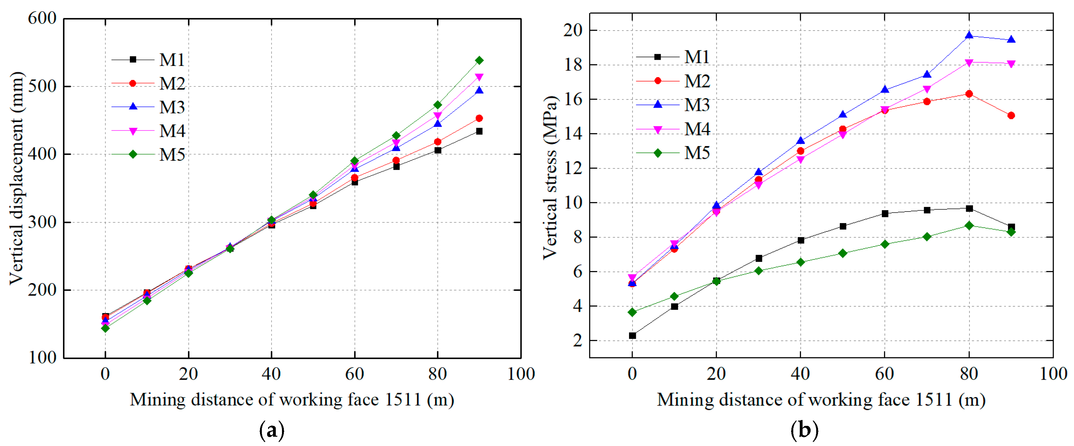
- (1)
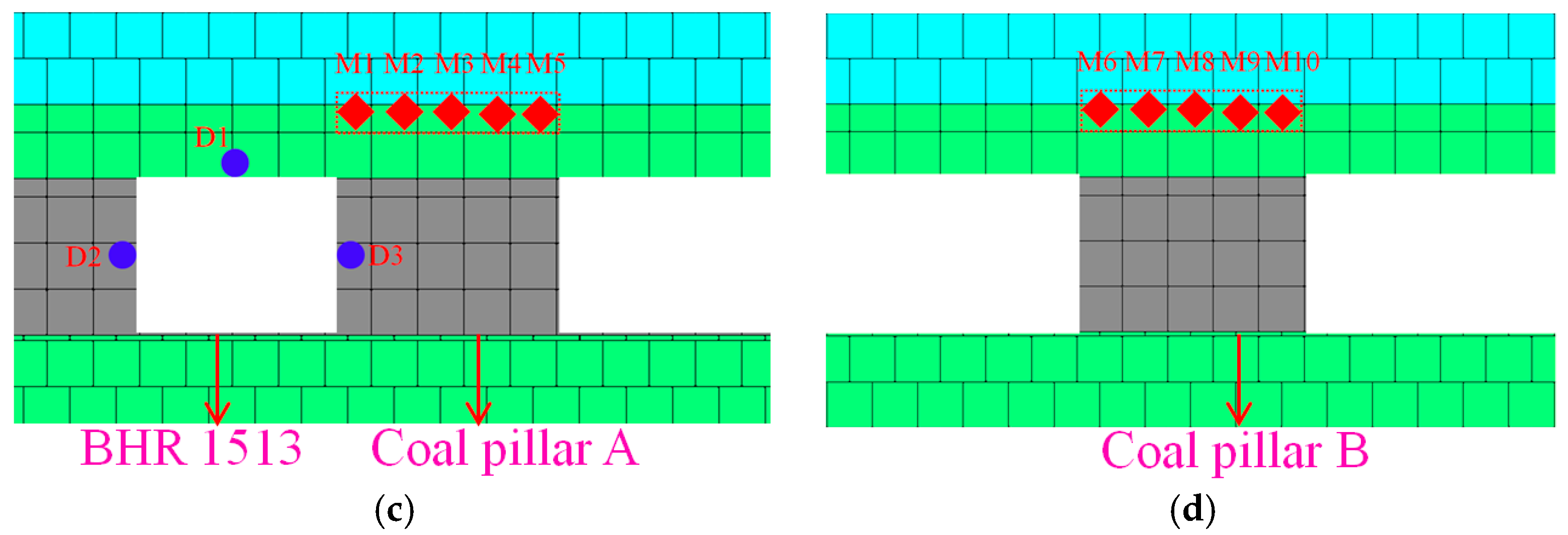
- During the gradual mining of working face 1511 towards the right, the vertical stress of the 5 measuring points above coal pillar A shows an increasing trend, while the increase rate shows a decreasing trend as a whole. When mining to 60~80 m, the vertical stress change curve tended to be flat. As the roof above coal pillar A suffers more pressure, the vertical displacement also increases continuously. Before mining to 60 m, the vertical displacement of 5 monitoring points above coal pillar A shows an increasing trend with the same amplitude. When mining to 60~90 m, the vertical displacement of 5 monitoring points begins to change, showing an increasing trend from M1 to M5, that is, the roof above coal pillar A begins rotating towards the right (rotate towards Strip goaf 1513). Moreover, when the working face 1511 mines towards the right to 90 m, the vertical displacement of the five measuring points differs largely, that is, the roof above pillar A continues rotating towards Strip goaf 1513;
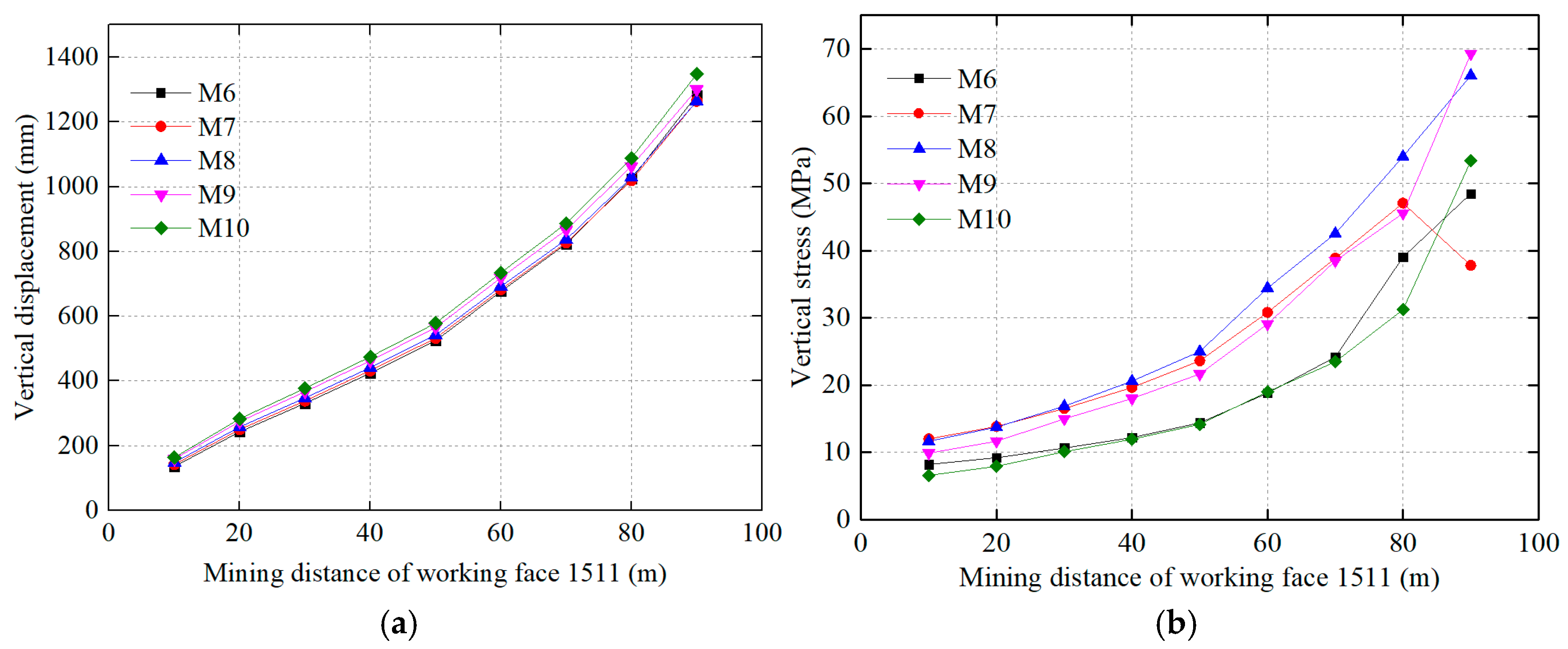
- (2)
- During the gradual mining of working face 1511 towards the right, the vertical stress of the 5 measuring points above coal pillar B shows an increasing trend, and so does the increase rate. The inflection point arrives when the working face 1511 mines to the distance of 60 m. Similar to coal pillar A, when the roof above coal pillar B suffers more pressure, the vertical displacement also increases continuously. According to the curve variation in Figure 10, when the working face 1511 mines to 90 m, the displacement of the measuring point M6 to M10 (the roof above the coal pillar B from left to right) increases slightly in turn, and the vertical displacement difference of the five measuring points increases, that is, the roof above the coal pillar B continues to rotate towards goaf 1511.
5.1.3. Surface Displacement of BHR 1513
- (1)
- There is an increase in the displacement of the roof and two coal sides during the mining of the working face 1511 towards the right. The solid coal sidewall sees the largest displacement increase (from 658 mm to 876 mm, an increase of 218 mm), followed by the roof (from 182 mm to 391 mm, an increase of 209 mm) and solid coal sidewall (from 467 mm to 490 mm, an increase of 23 mm);
- (2)
- When the mining distance of working face 1511 is within 60 m, the roof displacement shows a linear growth trend with a rapid growth rate, while the displacement of coal pillar sidewall grows slowly. When the mining distance of working face 1511 exceeds 60 m, the roof displacement velocity slows down, without obvious displacement, while the displacement velocity of the coal pillar sidewall increases significantly.
5.2. Discussion
6. Conclusions
- (1)
- Through theoretical analysis and numerical simulation, this study reveals the “transferring pressure across goaf” effect and its occurrence mechanism in gob-side roadways with small coal pillars under distant face mining. The results indicate that the island coal pillar collapses under the “T”-shaped strata stress after adjacent working face mining, leading to goaf interconnection, the subsequent breaking and rotation of key strata (KS), and severe disturbance to the roadway surrounding rock. These findings align with the research objectives stated in the Introduction, providing theoretical support for stability control in deep gob-side roadways;
- (2)
- Study Limitations: The numerical model is based on idealized geological conditions, ignoring the impact of complex faults or heterogeneous rock layers. Additionally, potential errors may arise from the laboratory-to-field conversion of coal-rock mechanical parameters, which could affect the accuracy of stress distribution predictions. Future studies should validate the model’s universality by integrating field monitoring data and addressing multi-scale geological complexities;
- (3)
- Future Research Directions: Subsequent investigations should focus on the dynamic response of roadways under multi-working-face collaborative mining and coupled stress fields. Further optimization of active pressure relief techniques (e.g., directional hydraulic fracturing) and synergy control strategies (e.g., graded anchorage systems) is critical to enhance anti-disturbance capabilities in complex stress environments. Additionally, real-time monitoring technologies and multi-physics coupling models should be developed to quantify spatiotemporal correlations between mining-induced stress and roadway deformation.
Author Contributions
Funding
Institutional Review Board Statement
Informed Consent Statement
Data Availability Statement
Acknowledgments
Conflicts of Interest
Abbreviations
| KS | key strata |
| BHR 1513 | belt haulage roadway 1513 |
| TTR 1511 | track transportation roadway 1511 |
| BHR 1511 | belt haulage roadway 1511 |
| K | bulk modulus |
| G | shear modulus |
| E | elastic modulus |
| v | poisson’s ratio |
| Er | elastic modulus of rock |
| Em | elastic modulus of rock mass |
| RQD | rock quality index, which is obtained by peeping at borehole BHR1513 |
| σc | compressive strength of rock |
| σcm | compressive strength of rock mass |
| j | coefficient, generally 0.56 |
| σtm | tensile strength of rock mass |
| k | coefficient, generally 0.05~0.1; the value in this calculation is 0.1 |
References
- Xie, S.R.; Li, H.; Chen, D.D.; Feng, S.H.; Yang, J.H.; Ma, X.; Jing, Z.S.; Xing, S.K. Research on the Control Technology and Key Parameters of External Anchor-Internal Unloading of Surrounding Rock During Gob-Side Entry Driving Under Severe Mining of 1000-m-Deep Mine. Rock Mech. Rock Eng. 2024, 57, 2913–2932. [Google Scholar] [CrossRef]
- Yang, J.; Liu, B.; Wang, Y.J.; Zhang, J.; Hou, S.L.; Wang, Y.K.; Wu, X.; Li, H.C. Roof control mechanism and partition compensation support technology of gob-side entry formed by N00 mining method in thin coal seam. J. Cent. South Univ. 2024, 31, 602–620. [Google Scholar] [CrossRef]
- Shan, R.L.; Liu, S.; Wang, H.L.; Li, Z.L.; Huang, P.C.; Dou, H.Y. Research on the deformation mechanism and ACC control technology of gob-side roadway in an extra-thick coal seam with varying thickness. Energy Sci. Eng. 2024, 12, 1913–1933. [Google Scholar] [CrossRef]
- Wang, Q.; He, M.C.; Li, S.C.; Jiang, Z.H.; Wang, Y.; Qin, Q.; Jiang, B. Comparative study of model tests on automatically formed roadway and gob-side entry driving in deep coal mines. Int. J. Mining Sci. Technol. 2021, 31, 591–601. [Google Scholar] [CrossRef]
- Huang, B.X.; Liu, J.W.; Zhang, Q. The reasonable breaking location of overhanging hard roof for directional hydraulic fracturing to control strong strata behaviors of gob-side entry. Int. J. Rock. Mech. Min. 2018, 103, 1–11. [Google Scholar] [CrossRef]
- Xu, X.H.; He, F.L.; Li, X.B.; He, W.R. Research on mechanism and control of asymmetric deformation of gob side coal roadway with fully mechanized caving mining. Eng. Fail. Anal. 2021, 120, 105097. [Google Scholar] [CrossRef]
- Zhang, N.; Li, X.H.; Gao, M.S. Pretensioned support of roadway driven along next gob and heading adjacent advancing coal face and its application. Chin. J. Rock Mech. Eng. 2004, 23, 2100–2105. [Google Scholar]
- Yu, Y.; Wang, X.Y.; Xue, G.Z.; Chong, D.Y. Dynamic sectional control technology of surrounding rock in gateway driving along goaf forward to mining face. Coal Sci. Technol. 2013, 41, 43–46. [Google Scholar]
- Bai, J.B.; Shen, W.L.; Guo, G.L.; Wang, X.Y.; Yu, Y. Roof deformation, failure characteristics, and preventive techniques of gob-side entry driving heading adjacent to the advancing working face. Rock Mech. Rock Eng. 2015, 48, 2447–2458. [Google Scholar] [CrossRef]
- Wang, M.; Bai, J.B.; Wang, X.Y.; Xu, Y.; Guo, Y.H.; Cao, J.L. The surrounding rock deformation rule and control technique of the roadway driven along goaf and heading for adjacent advancing coal face. J. Mining Safety Eng. 2012, 29, 197–202. [Google Scholar]
- Liu, J.H.; Cao, Y.Q.; Wei, Z.Q.; Shen, W. Research on reasonable width of partition pillar close to goaf heading mining in thick seam of deep shaft. Chin. J. Rock Mech. Eng. 2015, 34 (Suppl. S2), 4269–4277. [Google Scholar]
- Ma, D.P.; Wang, T.X.; Liu, Y. An analysis of “space-time” relationship of gob-side entry driving in dynamic pressure area. J. Mining Safety Eng. 2015, 32, 465–470. [Google Scholar]
- Gou, J. Research on surrounding rocks controlling technology of roadway in gob entry driving of face-mining. Coal Eng. 2018, 50, 43–47. [Google Scholar]
- Zhao, Y.; Wang, Y.; Gao, M.S.; Liu, B.T. Research and Application of Gateway Driving Along Goaf Forward to Adjacent Mining Coal Face in Chensilou Mine. Coal Eng. 2012, 6, 41–43. [Google Scholar]
- Yang, H.Q.; Han, C.L.; Zhang, N.; Sun, C.L.; Pan, D.J.; Dong, M.H. Stability Control of a Goaf-Side Roadway under the Mining Disturbance of an Adjacent Coal Working Face in an Underground Mine. Sustainability 2019, 11, 6398. [Google Scholar] [CrossRef]
- Han, C.L.; Zhang, N.; Xue, J.H.; Kan, J.G.; Zhao, Y.M. Multiple and Long-Term Disturbance of Gob-Side Entry Retaining by Grouped Roof Collapse and an Innovative Adaptive Technology. Rock Mech. Rock Eng. 2019, 52, 2761–2773. [Google Scholar] [CrossRef]
- Hou, C.J.; Li, X.H. Stability principle of big and small structures of rock surrounding roadway driven along goaf in fully mechanized top coal caving face. J. China Coal Soc. 2001, 26, 1–7. [Google Scholar]
- Su, H.; Bai, J.B.; Yan, S.; Chen, Y.; Zhang, Z.Z. Study on gob-side entry retaining in fully-mechanized longwall with top-coal caving and its application. Int. J. Mining Sci. Technol. 2015, 25, 503–510. [Google Scholar] [CrossRef]
- Wang, H.S.; Shuang, H.Q.; Li, L.; Xiao, S.S. The Stability Factors’ Sensitivity Analysis of Key Rock B and Its Engineering Application of Gob-Side Entry Driving in Fully-Mechanized Caving Faces. Adv. Civ. Eng. 2021, 2021, 9963450. [Google Scholar] [CrossRef]
- Xie, Z.Z.; Zhang, N.; Han, C.L.; An, Y.P. Research on principle and application of roof thick layer cross-boundary anchorage in coal roadways. Chin. J. Rock Mech. Eng. 2021, 40, 1195–1208. [Google Scholar]
- Geng, H. Study on the Stability Control Technology of Surrounding Rock for Gob-Side Entry Driving Foward the Mining Face Separate by a Narrow Goaf. Master’s Thesis, China University of Mining and Technology, Xuzhou, China, 2019. [Google Scholar]


| Serial Number | Lithology | Block Parameters | Contact Surface Parameters | Remarks | |||||
|---|---|---|---|---|---|---|---|---|---|
| Density/kg·m−3 | Elastic Modulus/GPa | Normal Stiffness/GPa·m−1 | Tangential Stiffness/Gpa·m−1 | Friction Angle/° | Cohesion/MPa | Tensile Strength/MPa | |||
| 26 | Fine sandstone | 2750 | 11.3 | 1020 | 408 | 28 | 14.9 | 3.8 | KS7 |
| 25 | Medium sandstone | 2630 | 11.7 | 1180 | 472 | 27 | 15.3 | 5.1 | |
| 24 | Grit stone | 2700 | 10.1 | 1090 | 463 | 26 | 14.3 | 4.2 | KS6 |
| 23 | Mudstone | 2300 | 3.5 | 462 | 341 | 26 | 8.5 | 1.6 | |
| 22 | Siltstone | 2510 | 9.6 | 1040 | 416 | 25 | 13.9 | 4.3 | |
| 21 | Medium sandstone | 2630 | 11.7 | 1180 | 472 | 27 | 15.3 | 5.1 | KS5 |
| 20 | Siltstone | 2510 | 9.6 | 1040 | 416 | 25 | 13.9 | 4.3 | |
| 19 | Fine sandstone | 2750 | 11.3 | 1020 | 408 | 28 | 14.9 | 3.8 | |
| 18 | Sandy mudstone | 2380 | 4.7 | 580 | 232 | 25 | 9.7 | 2.8 | |
| 17 | Siltstone | 2510 | 9.6 | 1040 | 416 | 25 | 13.9 | 4.3 | |
| 16 | Fine sandstone | 2750 | 11.3 | 1020 | 408 | 28 | 14.9 | 3.8 | KS4 |
| 15 | Mudstone | 2300 | 3.5 | 462 | 341 | 26 | 8.5 | 1.6 | |
| 14 | Siltstone | 2510 | 9.6 | 1040 | 416 | 25 | 13.9 | 4.3 | |
| 13 | Grit stone | 2700 | 10.1 | 1090 | 463 | 26 | 14.3 | 4.2 | KS3 |
| 12 | Mudstone | 2300 | 3.5 | 462 | 341 | 26 | 8.5 | 1.6 | |
| 11 | Coal | 1260 | 0.4 | 280 | 112 | 10 | 2.9 | 0.5 | |
| 10 | Siltstone | 2510 | 9.6 | 1040 | 416 | 25 | 13.9 | 4.3 | KS2 |
| 9 | Fine sandstone | 2750 | 11.3 | 1020 | 408 | 28 | 14.9 | 3.8 | |
| 8 | Siltstone | 2510 | 9.6 | 1040 | 416 | 25 | 13.9 | 4.3 | |
| 7 | Coal | 1260 | 0.4 | 280 | 112 | 10 | 2.9 | 0.5 | |
| 6 | Siltstone | 2510 | 9.6 | 1040 | 416 | 25 | 13.9 | 4.3 | |
| 5 | Fine sandstone | 2750 | 11.3 | 1020 | 408 | 28 | 14.9 | 3.8 | KS1 |
| 4 | Siltstone | 2510 | 9.6 | 1040 | 416 | 25 | 13.9 | 4.3 | |
| 3 | 3up coal | 1260 | 0.4 | 280 | 112 | 10 | 2.9 | 0.5 | |
| 2 | Siltstone | 2510 | 9.6 | 1040 | 416 | 25 | 13.9 | 4.3 | |
| 1 | Fine sandstone | 2750 | 11.3 | 1020 | 408 | 28 | 14.9 | 3.8 | |
Disclaimer/Publisher’s Note: The statements, opinions and data contained in all publications are solely those of the individual author(s) and contributor(s) and not of MDPI and/or the editor(s). MDPI and/or the editor(s) disclaim responsibility for any injury to people or property resulting from any ideas, methods, instructions or products referred to in the content. |
© 2025 by the authors. Licensee MDPI, Basel, Switzerland. This article is an open access article distributed under the terms and conditions of the Creative Commons Attribution (CC BY) license (https://creativecommons.org/licenses/by/4.0/).
Share and Cite
Yang, H.; Han, C.; Zhang, N.; Wang, J.; Chen, Q.; Liu, J.; He, S. Transferring Pressure Mechanism Across Gob-Side Roadway Goaf with Coal Pillar During Distant Face Mining: A Case Study. Appl. Sci. 2025, 15, 4274. https://doi.org/10.3390/app15084274
Yang H, Han C, Zhang N, Wang J, Chen Q, Liu J, He S. Transferring Pressure Mechanism Across Gob-Side Roadway Goaf with Coal Pillar During Distant Face Mining: A Case Study. Applied Sciences. 2025; 15(8):4274. https://doi.org/10.3390/app15084274
Chicago/Turabian StyleYang, Houqiang, Changliang Han, Nong Zhang, Jiande Wang, Qingguang Chen, Jie Liu, and Shenghan He. 2025. "Transferring Pressure Mechanism Across Gob-Side Roadway Goaf with Coal Pillar During Distant Face Mining: A Case Study" Applied Sciences 15, no. 8: 4274. https://doi.org/10.3390/app15084274
APA StyleYang, H., Han, C., Zhang, N., Wang, J., Chen, Q., Liu, J., & He, S. (2025). Transferring Pressure Mechanism Across Gob-Side Roadway Goaf with Coal Pillar During Distant Face Mining: A Case Study. Applied Sciences, 15(8), 4274. https://doi.org/10.3390/app15084274