Article

Common Information Model-Oriented Ontology Database Framework for Improving Topology Processing Capability of Distribution Management Systems Considering Interoperability

1
Smart Grid Research Division, Korea Electrotechnology Research Institute, Gwangju 61751, Republic of Korea
2
Department of Electrical Engineering, Kyungnam University, Changwon 51767, Republic of Korea
*
Author to whom correspondence should be addressed.
Appl. Sci. 2025, 15(8), 4105; https://doi.org/10.3390/app15084105
Submission received: 19 February 2025 / Revised: 31 March 2025 / Accepted: 2 April 2025 / Published: 8 April 2025

Abstract

:
The operation targets of the distribution management system (DMS) have become increasingly diverse and complex. This complexity stems from the integration of distributed energy resources (DERs) to achieve carbon neutrality, alongside the introduction of new facilities such as electric vehicle charging stations and IoT sensors into the power distribution network. As the distribution system diversifies, there has been a growing need for interoperability to address these challenges effectively. Numerous DMS applications rely on topology processing (TP) for analyzing and managing power network structure, and the demand for nodes to process the connectivity has increased with the addition of new operational equipment. The speed of TP decreases as the number of nodes managed by a single DMS increases. Consequently, the operational reliability of TP-based DMS applications declines due to a decrease in the performance of TP. This paper proposes a new framework leveraging ontology databases (ODBs) to improve the performance of TP in DMS under an interoperability environment. The presented framework identifies shortcomings of traditional DMS utilizing relational databases (RDBs) and proposes a remedy by employing an ODB framework to achieve faster TP performance based on the common information model (CIM) for ensuring interoperability between components within the DMS. To validate the efficacy of the proposed method, various case studies were conducted on the DMS managing the headquarters level actual distribution network of the Republic of Korea to compare the TP performance in the case of an RDB and an ODB applied to the DMS. Results of case studies demonstrate that the proposed CIM-oriented ODB framework for the DMS guarantees much faster TP speed than the one with an RDB.

1. Introduction

1.1. Framework and Motivation

The introduction of new power facilities and evolving grid operational strategies, including heightened interconnection of renewable energy sources, deployment of electric vehicle (EV) charging stations, and adoption of medium-voltage direct current (MVDC) interconnection technology, is reshaping the landscape of power distribution networks. With the global expansion of renewable energy, the capacity of newly installed distributed energy resources (DERs) has been continuously increasing, with total installed capacity expected to exceed 500 GW by 2030 [1]. As the share of distributed energy increases, the related market is also expanding, and substantial investments are being made to enhance grid operation reliability by transitioning to distribution system operators (DSOs). These investments encompass electrification, renewable energy integration, grid modernization, and digitalization. In Europe, investments are projected to exceed approximately 600 billion euros by 2030 [2]. The 10th Basic Power Supply Plan, as outlined by the Ministry of Industry of the Korean government, forecasts a rise in renewable energy generation to 21.6% by 2030 and to 30.6% by 2036 [3]. Additionally, the Ministry of Environment has unveiled the 2050 Long-Term Low-Carbon Power Generation Strategy, targeting a renewable energy generation share of 65–80% by 2050 [4]. As of 2021, in the Republic of Korea, the cumulative number of registered EVs and EV charging stations has been steadily increasing, reaching approximately 230,000 and 70,000 units, respectively [5]. Furthermore, the necessity of securing MVDC distribution operation technology by 2030 is indicated in the 4th Energy Technology Development Plan [6]. The increasing complexity and diversity of entities managed within a DMS to cover the medium-voltage grid necessitate an adaptable system capable of accommodating technical and business changes in distribution networks. Developing an advanced DMS with each shift in the power distribution system’s business environment is impractical. Furthermore, predicting the development and implementation of power facilities, crucial for ensuring the future efficiency and stability of the distribution system, poses significant challenges. Adapting to evolving business landscapes requires ensuring interoperability among components in the DMS. When a DMS facilitates interoperability among its internal components, it becomes capable of effectively responding to shifts in business dynamics. The flexibility and scalability inherent in DMS components allow for the addition of new features or processes, or modifications to existing ones, with minimal disruption to interactions among system components.

1.2. Literature Review

Efforts have been made globally to ensure a standardized way of exchanging data between internal components of a DMS, and the International Electrotechnical Commission (IEC) Technical Committee (TC) 57 CIM, defined in the IEC 61970, 61968, and 62325 standard series, has been adopted to ensure interoperability since it serves as the standardized information model for the operational IT systems of power networks, such as energy management systems (EMSs) and DMSs [7,8,9]. Refs. [10,11] emphasize communication standards and CIM applicable to data, while [12] deals with DMSs for smart grids considering CIM-based interoperability. Furthermore, the CIM-based standard open platform, GridAPPS-D, has been designed to develop advanced distribution applications in an advanced DMS [13,14,15,16], and new applications for the advanced DMS based on CIM have been developed [17,18]. Along with interoperability for components of a DMS, research on standardized data exchange between DSOs utilizing a DMS as an operating IT system and transmission system operators (TSOs) has been internationally conducted. The TDX-ASSIST project aims to design and develop novel information and communication technology (ICT) tools and techniques that facilitate scalable and secure information systems and data exchange between TSO and DSO based on CIM [19,20]. As the CIM-based standardized data exchange is becoming more important worldwide, a CIM-based DMS platform configuration with a CIM-friendly database is required to meet data exchange requirements for the new features and processes in an advanced DMS.
Traditionally, DMSs have been constructed on RDBs to uphold operational speed, reliability, and stability. Utilizing an RDB intuitively enables the representation of information, facilitating efficient and organized data management through structured tables. Furthermore, the inherent characteristics of RDBs ensure consistency and integrity, maintaining data synchronization. However, predefining table structures poses challenges in adapting flexibly to schema changes. Additionally, if a CIM-based DMS platform operates on an RDB, an object–relational impedance mismatch occurs between the object-oriented CIM and the RDB structure, which makes the RDB hard to intuitively represent CIM objects [21,22]. One solution to this challenge is leveraging an object–relational mapping (ORM) tool, such as SQLAlchemy, Hibernate, Django ORM, Entity Framework, and Sequelize, facilitating the mapping of object-oriented models to RDBs. However, while ORM tools address some issues, they fail to mitigate fundamental issues associated with transformation processing. These include performance degradation and increased query complexity stemming from transformation processes. RDBs still exhibit drawbacks such as difficulty in handling modifications to the information model and reduced TP speed [23,24], which is crucial for applications in a DMS based on TP, as it provides an analyzed and managed power network structure for TP-based applications such as load flow and state estimation. RDBs suffer from slower topological search speeds as they only allow index searches on primary keys. Consequently, using index searches to locate nodes for TP and their connected counterparts is complex and time-consuming, and this reliance on TP inevitably leads to performance degradation in TP-based DMS applications. Highly sophisticated relational SQL queries must be developed to conduct graph traversal and pattern discovery using large numbers of joins across CIM concepts, although several CIM-based commercial products utilizing RDBs with excellent performance, such as EcoStruxure ADMS from Schneider and Spectrum Power from Siemens, are available.
Research has explored the introduction of various databases, including object–relational databases (ORDBs) [25], and no-SQL databases [26,27] to a DMS based on CIM-oriented standard interfaces. Ref. [25] presents a design approach for an ORDB based on CIM, enabling flexible data conversion between the object-oriented and RDB paradigms through ORM. Although ORM is structured to streamline complexity and enhance development efficiency by automating ORM, it can inadvertently generate complex SQL queries or inappropriate joins during the mapping process, leading to performance degradation. Furthermore, database-specific features or optimized queries cannot be used due to the limitations of database optimization. While creating a more complex data model may alleviate the object–relational impedance mismatch, it can introduce dependencies on specific ORM tools, complicating future database changes. Regarding the utilization of graph databases (GDBs), Ref. [26] presented the limitations of existing RDBs in storing and processing large-scale ontologies and suggested a GDB-based approach. Ref. [27] proposed a design methodology for a GDB-based framework aimed at storing and processing data in power system applications. Both studies suggested storing large-scale ontologies using a GDB, which falls under the category of no-SQL databases and ODBs. However, neither study offered a specific implementation approach tailored for real-time DMSs. To date, there has been no research exploring the utilization of ODBs to improve TP performance in real-time DMS while ensuring guaranteed interoperability, as proposed in this study. A brief summary of these related works is presented in Table 1 to highlight their main contributions, strengths, and limitations in the context of CIM-based DMS and database approaches.

1.3. Contributions and Content Summary

The majority of previous studies have focused on researching the development of frameworks for managing ontology-based information models, rather than exploring methods to integrate an ODB as a component in a real-time DMS. Leveraging the adaptability and modifiability of CIM, research on information model frameworks capable of effectively accommodating information models has been actively conducted. As proposed in previous research, an ODB possesses the capability to adapt to changes in the information model and offers scalability, rendering it suitable for designing a repository to manage it. Moreover, an ODB can be utilized in the design of a CIM-based framework as a modeling environment for representing graphic information and conducting tests related to various power system operations.
ODBs offer a graph-based and schema-flexible approach to storing domain knowledge, in contrast to traditional RDBs that rely on fixed table structures. ODBs can represent CIM objects natively without transformation, making it easier to update information models and perform graph-based queries. This flexibility helps address key limitations of RDB-based DMS platforms, particularly in TP, where performance and scalability are critical.
While previous studies have proposed CIM-based frameworks and explored the potential of graph or ontology-based databases to store large-scale ontologies, most have remained at the conceptual level or lacked consideration for real-time operational environments. Based on the literature reviewed, this study is the first to implement and validate an ODB framework specifically designed for real-time DMS operations to enhance TP performance while maintaining full interoperability. The proposed framework is tested using actual distribution network data from the DMS operated by KEPCO in the Republic of Korea.
This study contributes to the field by presenting the first implementation and validation of an ODB framework specifically designed for real-time DMS operations to enhance TP performance while maintaining full interoperability. In particular, it identifies and addresses three key limitations of RDB-based DMS platforms:
  • The object–relational impedance mismatch between the object-oriented CIM and the table-based RDB structure
  • The inflexibility to accommodate changes in the information model due to rigid schemas
  • Performance degradation in TP stemming from inefficient graph traversal mechanisms in RDBs
Furthermore, techniques for using ODB as a database for CIM-oriented DMS are presented. When developing the DMS, interoperability can be secured by applying ODB based on model-driven development (MDD) and component-based development (CBD) methodologies, which have advantages in the three aspects presented above. Since the RDF schemas and corresponding payloads are inserted directly into the ODB schema and data, there is no object–relational impedance mismatch, and it is easy to change the DB schema. Additionally, both the ODB data and messages exchanged through middleware are composed of the RDF syntax, facilitating efficient topology search. Despite the benefits of the proposed framework, current limitations include the need for manual ontology modeling and instance mapping. Future work will focus on developing semi-automated tools to alleviate this burden and enhance the scalability of the framework, and will also consider the potential of extending the ODB framework through integration with smart grid technologies and large-scale IoT-based systems.
The structure of this paper is outlined as follows: the configuration and development methodology of a DMS ensuring interoperability with IEC TC57 CIM are presented in Section 2. Section 3 presents and analyzes the issues arising from applying RDBs in a CIM-based DMS structure. Section 4 presents a new framework for integrating ODBs into the CIM-based DMS to address the issues associated with traditional RDBs. In Section 5, case studies are described to validate the proposed framework and demonstrate its efficacy. Finally, the conclusion is in Section 6.

2. CIM-Based DMS Platform Structure Considering Interoperability
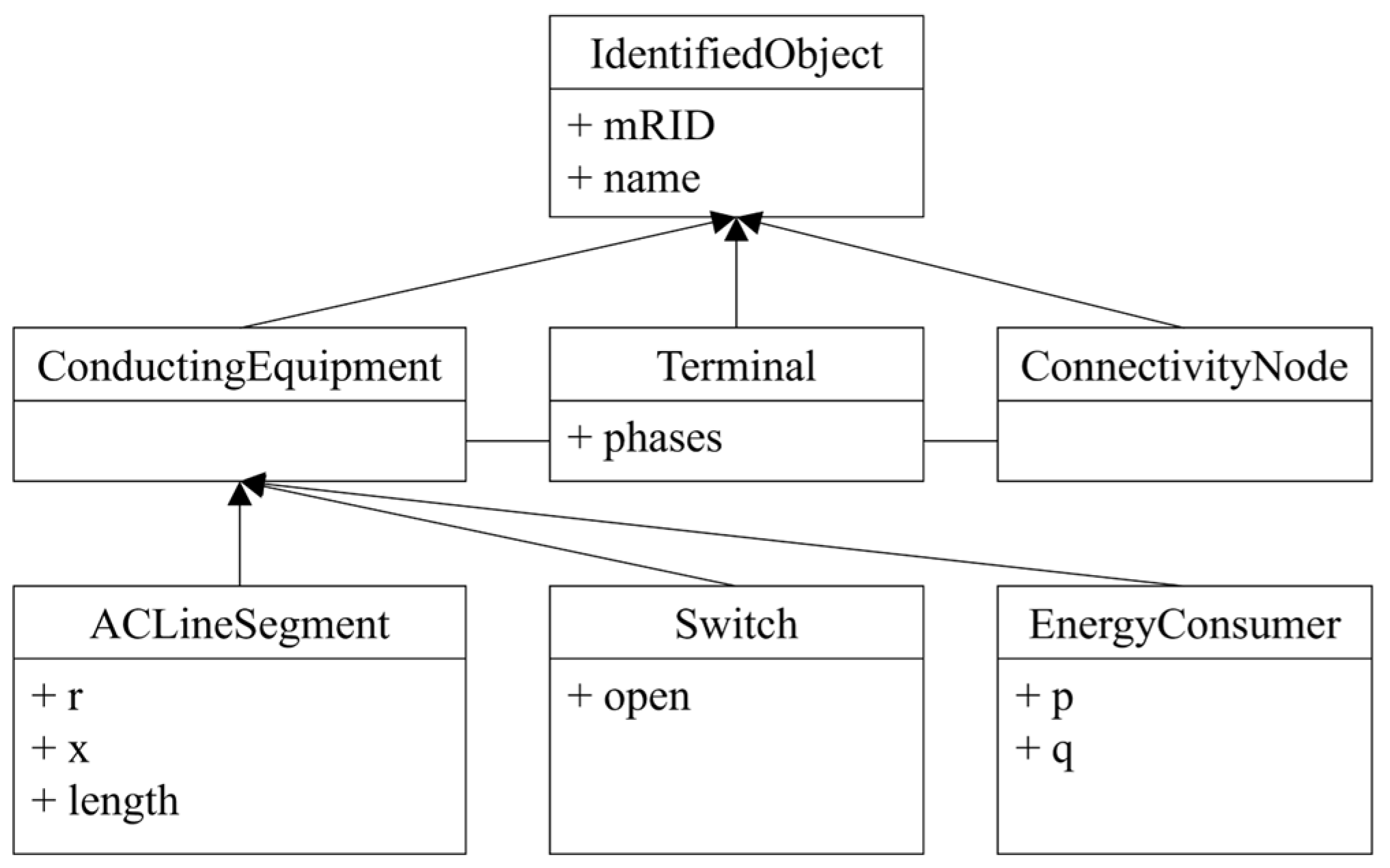
2.1. IEC TC57 CIM

The IEC TC57 CIM standard originated from EPRI’s control center API (CCAPI) research project [28]. Initially, the project aimed to streamline the process and cost of integrating new applications into EMSs or other systems while also minimizing investments in existing, well-functioning applications. It sought to provide an integrated framework for connecting existing applications and systems. The main objective of the IEC 61970 series is to integrate applications developed by multiple suppliers within a control center environment. It provides a comprehensive set of guidelines and standards to facilitate seamless information exchange with external systems of the control center. The IEC 61970 standard is structured based on the CBD methodology, which involves developing and combining independent components separately to construct a software system. By utilizing the CBD approach, applications can be integrated by modifying the component container, even changes in the communication layer.
The IEC 61970 standard defines the base CIM as the standard information model, which is crucial for ensuring interoperability among components within EMS [7]. CIM is an abstract model representing the various power system resources using object-oriented modeling techniques. In this study, the latest version of the CIM UML model officially released by the CIM User Group was adopted. The applied version, CIM UML 100.1.1.1, incorporates IEC 61970 version 17.40, IEC 61968 version 13.13b, and IEC 62325 version 3.17b. Released on 4 July 2022, this version supports the integrated application of the three CIM standards. To provide a clearer overview of the scope and purpose of these standards, Table 2 summarizes the key features and application fields of the IEC 61970, IEC 61968, and IEC 62325 standards.
It enables the modeling of logical information, such as equipment or voltage/current required for actual power system operations, into recognizable object forms. These objects are represented by classes and attributes, organized into logical packages, each corresponding to a specific part of the entire power system. A subset of the complete CIM is referred to as a profile that contains only the corresponding information for a specific data exchange. Figure 1 shows the Unified Modeling Language (UML) diagram of the profile representing network topology. It includes classes such as ConductingEquipment, Terminal, and ConnectivityNode. ConductingEquipment models equipment that is responsible for conducting electricity and serves as a top-class entity encompassing various power system components such as ACLineSegment, Switch, and EnergyConsumer. Terminal represents the physical junction that connects multiple ConductingEquipments, while ConnectivityNode serves as a node facilitating connections between ConductingEquipments. Each ConductingEquipment is connected through Terminals. Figure 2 shows how to represent a simple distribution network in CIM. It depicts a structure that connects Terminals at both ends of ConductingEquipment and connects Terminals to ConnectivityNodes. If the connections in the real system of Switch1, Branch7, and Load5 are expressed by CIM, then Switch1, Branch7, and Load5 correspond to Switch1, ACLineSegment7, and EnergyConsumer5, respectively. The interconnection of Switch1, ACLineSegment7, and EnergyConsumer5 can be expressed by ConnectivityNode3 connecting Terminal2 for Switch2, Terminal6 for ACLinesegment7, and Terminal4 for EnergyConsumer5.

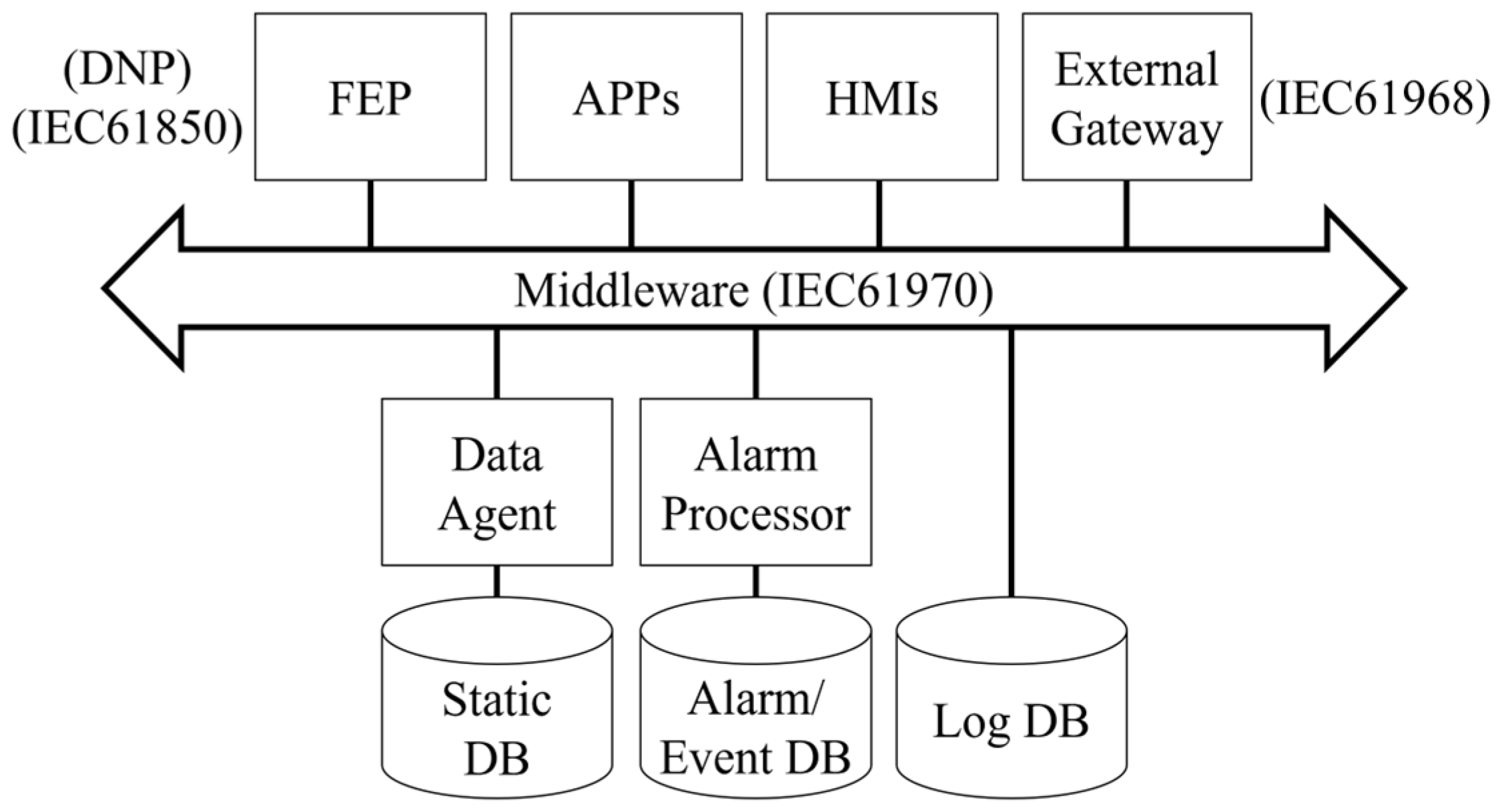
2.2. CIM-Based Distribution Management System

DMS is an IT system designed to remotely monitor and control the distribution network, aiming to improve the reliability and efficiency of a distribution system. As shown in Figure 3, the operating system can collect data generated by the terminal devices through the front-end processor (FEP) to monitor and control the status of the terminal devices installed on-site. Data exchange can occur via the DNP protocol with terminal devices. Additionally, interconnection to other systems can be facilitated through an external gateway [8]. Internally, the components of the DMS can exchange data based on the IEC 61970 standard, ensuring interoperability among them. The DMS comprises an information model, middleware, database, FEP, human–machine interface (HMI), and relevant applications. The information model represents the data model that DMS components intend to exchange with each other. Middleware functions as a data bus, providing communication and data exchange between components through messaging. The database is a comprehensive set of data managed and integrated by numerous individuals, allowing for systematic storage, integration, and structuring of data. The FEP communicates with terminal devices and wired/wireless communications networks using defined protocols to transmit data to the central control device. The HMI provides operators with real-time system status information via a screen interface. Lastly, the applications provide a variety of modules designed to operate systems efficiently, including load flow calculation, voltage control, as well as fault location, isolation, and service restoration (FLISR).
Applying CIM to a DMS platform enables the establishment of a CBD-based development environment, allowing the management of DMS elements at a component level. Similarly to assembling IC chips or electronic components to create a PCB board, various components can be combined to develop a DMS. Moreover, leveraging standard interfaces allows multiple vendors to participate in building a single DMS without needing to develop all necessary technologies from scratch. With a platform supporting CIM-based standard interfaces, components can be installed in the application storage, allowing for flexible utilization. To establish such a platform, the database must comply with CIM standards. The information model may evolve with the addition, modification, or removal of new models to accommodate changes in the power industry business. However, as the RDBs are designed for CIM compliance, they may become increasingly complex and lose the advantages associated with RDB usage. To support such a CIM-based platform, the underlying information model must be clearly defined and systematically managed. In this context, the CIM is defined using UML class diagrams, and standard tools such as CIMTool and Enterprise Architect (EA) are utilized to automatically convert the model into RDF and XML representations. Furthermore, CIM extensions are conducted based on a structured methodology involving use case definition, business object design, and gap analysis, following the procedure proposed in [29].

3. Comprehensive Analysis of Issues of CIM-Based DMS Using RDB

This section analyzes and describes issues arising from the introduction of an RDB to a CIM-based DMS. Traditional DMS platforms have primarily utilized RDBs. The DMS database is primarily used to store static network models and historical data regarding the operation of a distribution system, as well as for managing alarms, ensuring real-time operation, consistency, and reliability of the data managed in the database. RDBs store data in a fixed tabular format, making information simple and intuitively represented, thus easily perceivable by humans. By utilizing an RDB, it is possible to efficiently and systematically manage structured data in the form of tables. Owing to the inherent characteristics of RDBs, they can ensure data integrity and maintain consistency by continuously synchronizing information. By implementing queries effectively, it is possible to increase search speed by utilizing the fixed structural characteristics of the database. In some cases, joining tables can be used to improve search speed, but as the number of joined tables increases, readability decreases, and query execution time significantly increases. The time complexity for finding ‘m’ elements in ‘n’ tables using queries in a traditional RDB is O m log 2 n . As the complexity of the join query increases, additional parameters contribute to the time complexity of the query process. Despite the numerous advantages of RDB as a database type, CIM-based DMS can encounter various issues. In an object-oriented CIM-based DMS, using an RDB can lead to object–relational impedance mismatch, difficulties in adapting to information model changes, and decreased performance in TP.

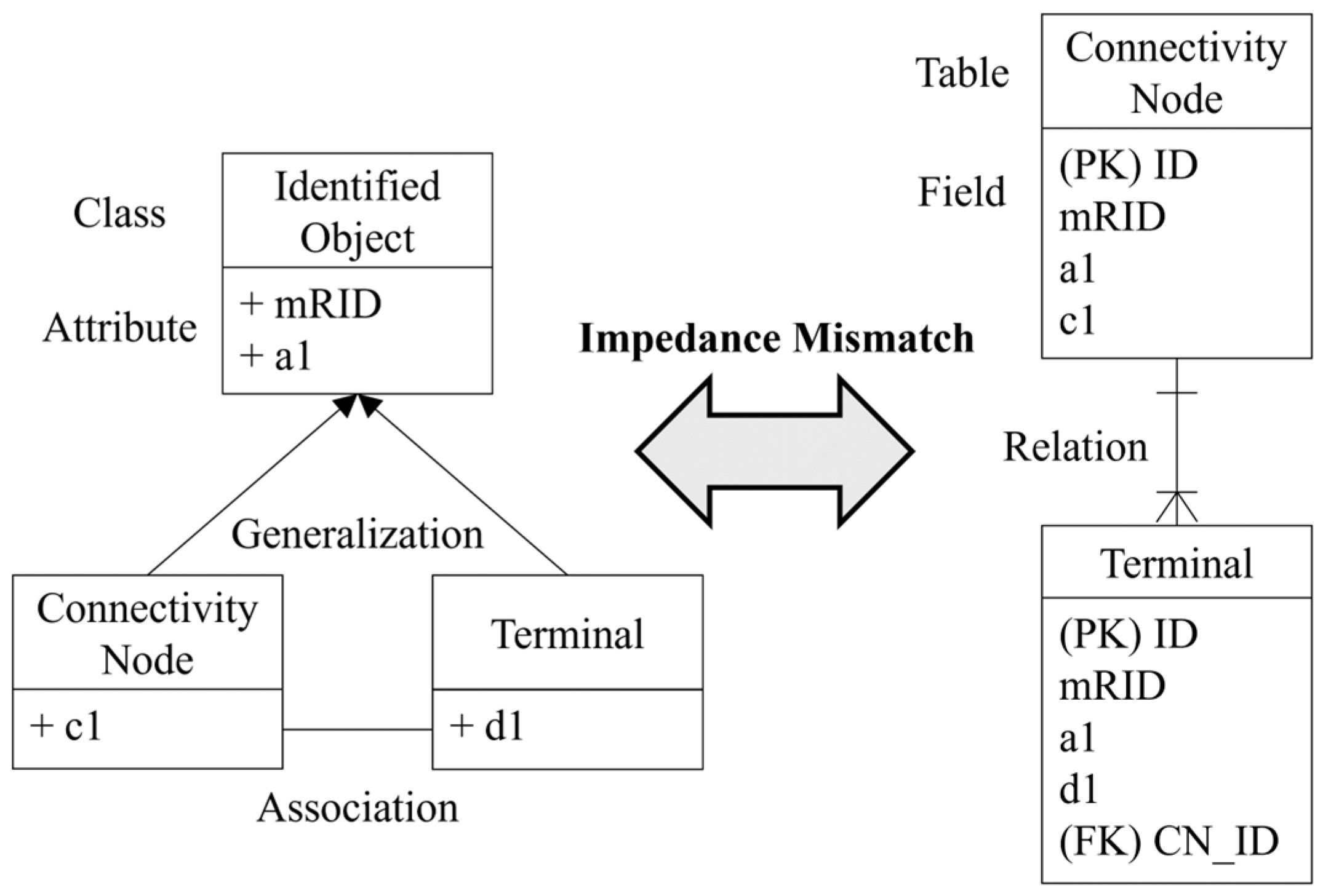
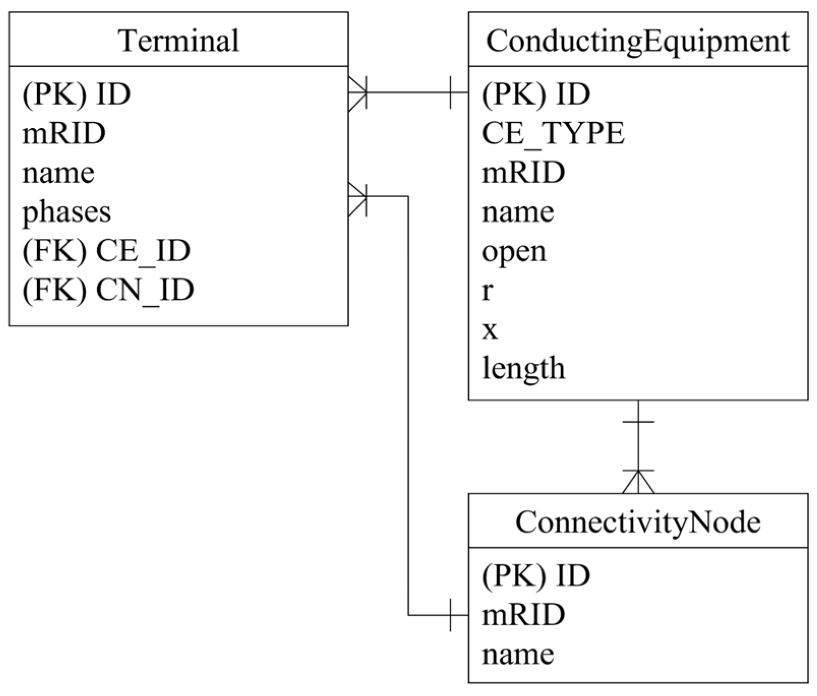
3.1. Object–Relational Impedance Mismatch

When utilizing an RDB, the problem of impedance mismatch between CIM objects and relations arises [22]. Storing data received from a component in the middleware into the database results in an impedance mismatch with the data model. Object-oriented languages support inheritance, polymorphism, and association, allowing data representation as an object graph. RDBs represent data in the form of tables and columns, storing data using relationships between tables, which can lead to inconsistencies between objects and table models. Object–relational impedance mismatch is discussed in terms of granularity, inheritance, identity, association, and data retrieval perspectives. The object model can be more granular than the relational model, resulting in an object model composed of more classes than the number of tables in the database, as shown in Figure 4. RDBs lack support for the concept of inheritance. In power distribution systems, switches are classified into reclosers, circuit breakers, and load break switches based on their characteristics. In CIM, the ProtectedSwitch class is defined as the parent class, with the Recloser, Breaker, and LoadBreakSwitch classes as its child classes, inheriting from the ProtectedSwitch class. Because of the absence of inheritance support, RDBs require designing one table for each object or designing each class as a table. RDBs ensure exactly one identity through the concept of primary keys, whereas objects define both identity and equivalence. Correlations in RDBs are defined by foreign keys, which lack directionality. In contrast, objects exhibit directionality in their correlations and bidirectionality by defining the association twice. In object-oriented applications, a graph traversal method is employed, starting from one object and connecting to others through links. In RDB, data exploration is performed using joins to minimize the number of SQL queries. Various entities are loaded, and the desired entities are selected through a join.
An RDB is a database that organizes data in a tabular format and establishes correlations between data through foreign key relationships. The table structure should be designed to enable ORM of the object-oriented model to the RDB. The table design methods for expressing object-oriented can be largely divided into two approaches. The first approach involves designing tables at a class level, representing individual objects. In this case, the process of object creation and query execution becomes complex due to the table, resulting in a significantly slower processing speed. By utilizing foreign key relationships, all correlations (association, aggregation, generalization) in CIM are expressed, making it impossible to distinguish correlations in the RDB. Secondly, to minimize the number of join operations between tables, designing tables at the object level is feasible. However, designing tables on an object-by-object basis can hinder the scalability of the model and render it vulnerable to maintenance issues.
Figure 5a represents the tabular representation of the IdentifiedObject, ConnectivityNode, and Terminal classes presented in Figure 4. When designing a table at the class level for the child classes of IdentifiedObject, namely ConnectivityNode and Terminal, tables for IdentifiedObject, ConnectivityNode, and Terminal can be created as shown in Figure 5a. Each table contains attributes as fields, and foreign keys can be added in the child classes’ fields to represent the inheritance relationship. To create a ConnectivityNode object with mRID ‘563’, both the IdentifiedObject and ConnectivityNode tables need to be explored. By using the foreign key ‘IO_ID’ in the ConnectivityNode table, the record in the IdentifiedObject table corresponding to the parent class of the object can be retrieved, allowing the creation of a complete object. Similarly, for Terminals, exploration of both the IdentifiedObject and Terminal tables is required, and objects can be created using the foreign key ‘IO_ID’ in the Terminal table. The topology of ConnectivityNode and Terminal can be explored using the foreign key ‘CN_ID’ in the Terminal table.
If the table is designed at the object level, as shown in Figure 5b, the ConnectivityNode table can incorporate the attributes of the parent class, IdentifiedObject, to reduce the need for joins. Designing tables at the class level by incorporating the attributes of the parent class, the query complexity decreases compared to designing tables at the parent class level, similar to Terminal. However, if a new child class is introduced in the Terminal due to changes in CIM, the structure of the table becomes more complex as new attributes are added to the Terminal table. When two or more new child classes are added, each with additional attributes, there may be unused attributes depending on the object. If fields defined in a database are never used, space is wasted. Executing a table query that includes unnecessary fields takes a significant amount of time to read and write data, resulting in degraded performance. The readability of the table is poor, causing confusion during maintenance work. Furthermore, maintaining data integrity can be challenging, leading to potential inconsistencies.

3.2. Difficulty of Changing Database Schema

With the rising usage of EVs, charging stations for them are being integrated into the power distribution network. Additionally, new facilities such as converter stations and soft-open points (SOPs) are being introduced with the emergence of DC networks. These new elements impact not only the components but also the operation and system of the distribution network. As the power business progresses, the information model for a DMS undergoes modifications. Conversely, if certain equipment becomes obsolete, the associated information model is deleted. If the same element has a different usage concept or is expanded, changes to the information model become imperative. Figure 6 illustrates changes in the information model, reflecting additions of new equipment, removal of existing ones, and modifications of existing components, due to the transformation of the power distribution network operating system. Upon implementing the SOP for operating the DC power distribution network, the new SoftOpenPoint class can be introduced to the existing information model. In scenarios where SOP replaces the existing switch equipment, the Switch class might be removed. Given that the existing information model addresses AC networks, adjustments can be made to accommodate DC networks by converting the ACLineSegment class to the LineSegment class.
An information model can be extended or modified to accommodate new data requirements arising from new demands or business needs. Due to the characteristics of the information model, the CIM-based DMS can adapt to changes in the power business. However, aligning the schema in the RDB with the updated information model in the DMS necessitates modification. However, RDBs are not structured to easily accommodate changes in the data model. They come with constraints aimed at maintaining data consistency, and altering the schema changes entails additional effort to ensure data integrity. Complex tasks, including modifying table structures and constraints, rebuilding indexes, and adjusting correlations between tables, are necessary. These tasks impact multiple components connected to the database, leading to confusion and increased costs for schema modifications. The scenario where a database schema is altered due to modifications in the information model can be classified as shown in Figure 7. Changes in CIM components are classified into modifying, deleting, and adding. Modifications to CIM elements are classified as changes in class names, attribute names, and correlations. Correlations can transit between association and aggregation, and vice versa. The generalization relationship may also change, or aggregation or association may transit to generalization. Deletion of CIM elements falls into three categories: class deletion, attribute deletion, and correlation deletion. The addition of CIM elements can be classified into cases where the top-level class, sub-class, or attribute name is added, as well as when aggregation, association, or generalization is added. Types of correlations include aggregation, association, and generalization.
Various scenarios for database schema changes are shown in Table 3. If there are modifications, deletions, or additions to the new CIM elements, the database schema must undergo alterations and migration. Migration involves transferring data from an existing database to a new one in accordance with its structure. Analyzing changes in the information model is necessary to redesign certain components based on the existing RDB schema, considering the modifications. A database migration file can be generated to modify the RDB schema according to the redesigned schema. The complexity of schema changes varies depending on whether the existing database schema is tabulated with classes or objects. In the modification depicted in Figure 5a, classes, attributes, and correlations are mapped, respectively, to tables, fields, and foreign key relationships. When objects are tabulated, as shown in Figure 5b, attributes are mapped to fields, while classes and correlations are handled differently depending on the situation. As shown in Table 3, when converting classes into tables from the perspective of database schema changes, the process is relatively straightforward and not excessively complex, as it involves a direct one-to-one mapping of elements. Mapping classes, attributes, correlations, and associations to tables, fields, and foreign key relationships simplifies the modification process. However, when objects are tabulated, handling schema changes becomes more intricate, necessitating consideration of tables, fields, and foreign key relationships in certain cases. For instance, adding more than two new child classes may result in unused fields depending on the record. Redesigning the schema of a table based on its lowest child class to eliminate unnecessary fields complicates the database migration process. Furthermore, if DMS components are directly accessing the database to retrieve data, the impact of information model changes on the DMS is amplified. In such cases, not only is modifying the database schema necessary, but also adopting the code where DMS components access the database.

3.3. Degradation of Topology Processing Performance

The operational landscape of advanced DMS in the Republic of Korea has evolved significantly, now boasting about 430,000 operational nodes. This growth can be attributed to the expansion of the power network, the proliferation of terminal devices, and the rise in DERs. The power network exhibits a radial-typed topology, where most DMS applications, including load flow analysis, system reconfiguration, state estimation, and FLISR, rely heavily on efficient TP. The performance of several key applications crucial for managing the power distribution network is directly influenced by the performance of TP. The load flow analysis application is software designed to calculate the magnitude and phase of voltages at each node based on network topology information. For optimal functionality, this application necessitates the accurate input of precise topology data. It facilitates the determination of the operating cycle of applications, adaptable to the operator’s needs or requirements. During the system design phase, it plays a crucial role in running system analysis applications to verify and address potential issues within the network, especially in worst-case scenarios. Furthermore, it serves as a core feature within the system reconfiguration application. The FLISR application is pivotal in detecting faults within the distribution network, identifying the affected section, and devising the most efficient recovery plan. Incorporating topology processing functionality is crucial for pinpointing fault sections accurately. However, the recent expansion of the distribution network has led to a slowdown in the time for TP within the RDB-based DMS. The TP to handle a specific distribution network area in a headquarters takes about 90 [s], a critical factor for event-mode applications such as FLISR. Event-mode applications operate in response to specific events, and the performance of a FLISR application depends on its ability to swiftly react to occurrences such as malfunctions or overloads. Considering that the target time for FLISR of advanced DMS in the Republic of Korea is 180 [s], a topology processing time of 90 [s] alone could potentially pose challenges.
The RDB-based DMS utilizes B−Tree or B+Tree data structures to search for correlations between ConductingEquipment, Terminal, and ConnectivityNode, enabling rapid index search. In RDBs such as MySQL and PostgreSQL, the B+Tree structure is commonly used for index searching. In a B−Tree, each node can house multiple keys and children. These keys are organized in sorted order, with each key being sorted into a left subtree containing values smaller than itself and a right subtree containing values larger than itself. B−Trees boast more branches compared to binary trees, allowing them to store a greater number of keys. Their nodes accommodate multiple keys, resulting in a relatively low tree height depending on the key count. This feature facilitates the efficient processing of extensive data sets. A B+Tree, an advanced structure derived from a B−Tree, comprises internal and leaf nodes. Internal nodes exclusively store keys, while leaf nodes store values. In a B−Tree, all leaf nodes form a linked list, necessitating a search from the root node when seeking adjacent leaf nodes. However, a B+Tree allows for linear search on the leaf nodes, resulting in a significant reduction in time complexity. This structure finds widespread use in large-scale database systems, proving efficient for range searches and sequential access. As shown in Table 4, it is observed that binary trees exhibit a straightforward structure, while B−Trees and B+Trees are specialized for large-scale data and index structures.
In RDBs, correlations for TP can be expressed through foreign key relationships between tables. The TP involves exploring these foreign keys. As shown in Figure 8, the database is designed so that the Terminal class holds information about the ConductingEquipment and ConnectivityNode topology at both ends. Consequently, only Terminals with primary keys can be searched using the index. However, when exploring correlations between foreign keys, ConductingEquipment, and ConnectivityNode, index exploration becomes impractical. This limitation results in extended processing times for TP.
In RDBs, indexes are typically set only for primary keys due to their inherent characteristics. An index serves as a method to efficiently manage and swiftly search for data. Although utilizing an index allows for efficient searching of records, there are limitations on the types of data that can benefit from it. In RDB, indexes are automatically generated only for primary keys and not for any other columns. Consequently, searching for data based on the primary key can be swiftly executed using an index. However, when searching for other columns, the index cannot be utilized, necessitating sequential scanning of the entire record. To locate a specific record, the database must sequentially search through all records, resulting in a slow topological search speed. As the volume of data increases, the speed of searching decelerates, and the time complexity increases exponentially, as shown in Equation (1). These constraints contribute to the reduction in the speed of topology exploration in RDB. This issue becomes particularly pronounced in databases handling large-scale systems. To extract and analyze topology information effectively, a faster search speed is advantageous. Equation (1) reflects the worst-case time complexity of an RDB, which requires multiple nested joins to process relational queries.
O h R D B = O n 2
Figure 9 depicts an example of topology processing using data stored in an RDB based on the conceptual model presented in Figure 2. When exploring Terminal8 for the first time, it is essential to verify that the IDs of the ConnectivityNode and ConductingEquipment connected to Terminal8 are 7 and 9, respectively. Subsequently, the next step involves searching for the Terminal with ConnectivityNode ID ‘7’. As the only primary key, ID, of the Terminal table permits index searching, it becomes necessary to search through all Terminals to confirm if the ConnectivityNode ID is ‘7’. Therefore, the time complexity of the RDB search increases to O n 2 . Conversely, in a B+Tree structure, employing index search yields a time complexity of O n log 2 n . However, since the ConductingEquipment and ConnectivityNode fields lack primary key status, index search remains unattainable.

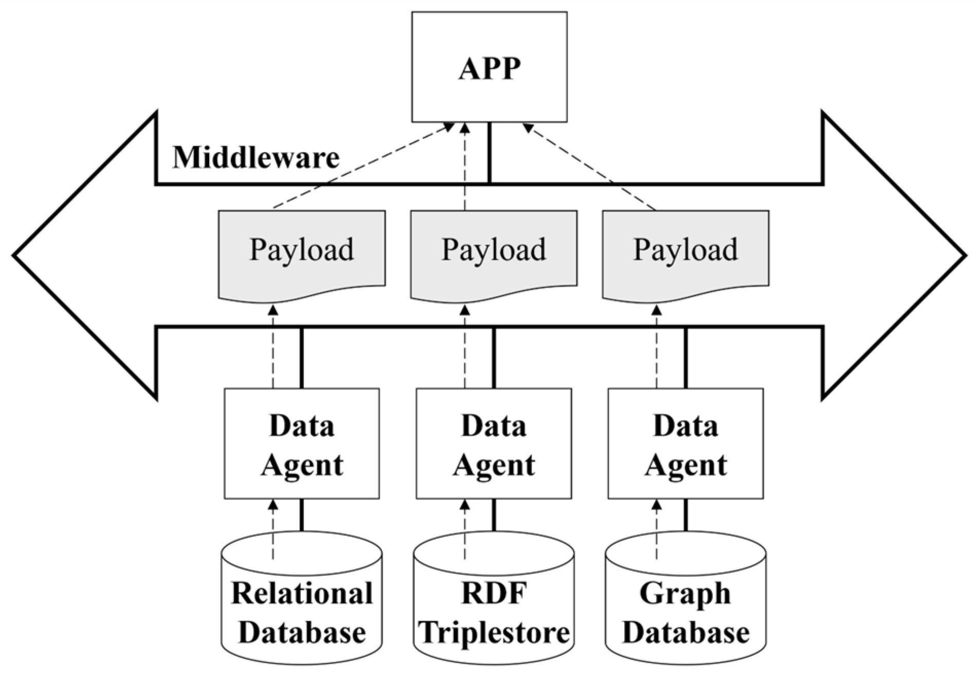
4. The Proposed CIM-Oriented Ontology Database Framework for DMS

In this paper, we propose a new CIM-oriented ODB framework to address the issues caused by the use of RDB in Section 3 and implement an ODB within DMS. Ontology entails the definition of components within a particular domain and a specification of relationships between them. An ODB is a database that stores ontologies in the form of a knowledge graph, using standards such as RDF or the Web Ontology Language (OWL) to represent ontologies. It can store or output files in RDF format in a triple structure, and it can also be represented in RDF graph format. RDF is an XML-based framework for describing metadata about a particular resource and stores data in the form of a triple that treats the resource, attribute, and attribute value as a unified unit. In this structure, resources, attributes, and values of attributes correspond to subjects, predicates, and objects of the triple structure, respectively. Multiple sets of triples can be merged if they have the same node name. By connecting these triples, we can create an RDF graph structure, establishing relationships between resources. This graph-based structure is convenient for TP, so an ODB suitable for TP has been implemented. Leveraging these characteristics can enhance the TP speed compared to that in the RDB-based DMS.

4.1. Development Process of the CIM-Oriented DMS Using an Ontology Database

Integrating an ODB into a DMS involves five distinct stages. First, determining the appropriate ontology types for the DMS is essential. This requires analyzing use cases to consider the types of data that will be represented and managed within the system. Second, based on the results of the requirements analysis, designing an ontology becomes imperative. This ontology can be represented as an information model comprising classes, attributes, and associations, enabling the expression of relationships between entities and objects. Third, it is possible to construct an ODB in the form of an RDF triple graph based on the designed information model. Fourth, integrating the ODB into the DMS necessitates a database inference engine. This engine functions as the input–output interface of the internal components of the DMS, receiving a profile input in the form of a schema and producing the corresponding payload as output. The components of DMS can exchange data stored in the ODB through an inference engine. Finally, the system should be adaptable to future changes or expansions. The information model can be modified, added to, or deleted according to evolving business needs, and the ODB is designed with a flexible structure to handle this. It must be possible to maintain additions, changes, and deletions of new or existing classes, attributes, and associations.
Figure 10 illustrates the CIM-oriented DMS development process based on the integration of MDD and CBD methodologies. In the MDD approach, an information model is first designed as a Platform-Independent Model (PIM) using standard modeling tools such as EA. This model is then transformed into a Platform-Specific Model (PSM) by deriving interface specifications, including RDF Schema (RDFS), XML Schema (XSD), and Interface Definition Language (IDL) based on the CIM structure [30].
From the PSM outputs, interface-specific software components such as adaptors are automatically generated using a code generator, allowing a seamless transition from abstract models to implementation. Meanwhile, the CBD approach supports the modularization of the system into independently manageable components. Each component is connected to the middleware through its own adaptor, and the middleware facilitates communication with the ODB via a data agent.
The data agent, equipped with RDF inference capabilities, enables semantic reasoning and accommodates changes in information models. All internal components conform to CIM-based interface profiles, allowing for consistent and standardized data exchange across the DMS. This integrated MDD–CBD methodology supports automatic interface generation and flexible service composition, thereby enhancing the scalability, maintainability, and interoperability of the system under evolving policy and operational requirements.

4.2. Details of Ontology Database Utilization

The ODB stores data in RDF files, allowing it to be structured in a subject–predicate–object (S-P-O) format. Since the object-oriented information model used as an interface between components can be directly converted into a database without any transformation, there is no occurrence of object–relational impedance mismatch. The ODB allows for the flexible import and export of data in the CIM/RDF/XML file format. The RDF inference engine, depicted as ‘Data Agent’ in Figure 11, acts as an interface service connecting the middleware to the ODB. Within the ODB, data are stored in the RDF triple. An ontology for the power network operating system, encompassing the power network, facilities, and operational technology, can be defined. This ontology can be modeled as an information model based on IEC TC57 CIM, and it can be represented in the form of RDF triples. As opposed to an RDB, an ODB does not require a schema design phase because the information model itself represents the database. The information model itself serves as both the schema and payload of the ODB. By utilizing the data agent, it is possible to define and map profiles for the interface between applications, in addition to handling changes in information models. The proposed ODB-based DMS framework can accommodate diverse communication models among system components by flexibly defining CIM-based interface profiles. This aligns with recent studies, such as [31], which emphasize the need for customizable architectures in distributed energy systems to support heterogeneous interaction patterns.
Figure 12 shows a portion of the interface schema that is stored in the ODB in the form of S-P-O triples. The schema for the Switch class is defined by inputting ‘S’, ‘P’, and ‘O’ as base:Switch, rdf:type, and rdf:Class, respectively. Since the class name that we want to define is Switch, ‘S’, ‘P’, and ‘O’ are entered as base:Switch, rdfs:label, and “Switch”@en, respectively. The comment representing the description of Switch is entered as base:Switch, rdfs:comment, and ‘Description of Switch’ for S, P, and O, respectively. Since the Switch class is part of the Wires package, ‘S’, ‘P’, and ‘O’ are entered as base:Switch, cims:belongsToCategory, and base:Package_Wires, respectively. As the superclass of Switch is IdentifiedObject, ‘S’, ‘P’, and ‘O’ are entered as base:Switch, rdfs:subClassOf, base:IdentifiedObject, respectively.
Figure 13 shows the switch data as part of the payload, stored in the ODB as an S-P-O triple. Since the mRID of the Switch is ‘10992901066’, ‘S’, ‘P’, and ‘O’ are entered as base:10992901066, rdf:type, and cim:Switch, respectively. The value of the attribute IdentifiedObject.aliasName for the object with mRID ‘10992901066’ in Switch is ‘Switch4964’. Therefore, ‘S’, ‘P’, and ‘O’ are entered as base:10992901066, cim:IdentifiedObject.aliasName, and “Switch4964”, respectively. The values of the Switch.locked attribute are set to ‘S’, ‘P’, and ‘O’ with the respective input values of base:10992901066, cim:Switch.locked, and “false” because the Switch.locked property is false. The remaining attributes are also stored in the ODB in RDF triple format, following the same method as described above.
Data can be exchanged between the ODB and other components in DMS by referring to a defined schema that specifies the syntax in which the syntax of the data to be exchanged is defined and by generating a payload accordingly. The profile intended for transfer from the ODB to other components represents a subset of the complete information model stored in the ODB. The schema for a specific profile can be used as the desired data exchange between components in the form of a payload. By utilizing an RDF inference engine, one can parse the schema to determine the composition of the profile in terms of classes and properties and subsequently extract the corresponding data from the database. This capability allows for accommodating new profiles as they are created. Figure 14 shows how an RDF inference engine can derive a payload using a schema and data from ODB as input. The RDF inference engine parses the schema to determine the structure of the desired output data and then retrieves the corresponding data from the ODB to generate the output in the form of a payload. By parsing the schema, it is possible to confirm that the class is Switch and that the Switch class includes the properties IdentifiedObject.aliasName and Switch.locked. With knowledge of the structure of the payload to be output, we will proceed to explore and store all instances of ‘S’ in the ODB where ‘P’ is rdf:type and ‘O’ is cim:Switch. Then, for all the ‘S’, ‘O’ whose ‘P’ is IdentifiedObject.aliasName and Switch.locked is stored, and finally a payload is generated by using the stored ‘S’ and ‘O’. This payload facilitates the input and output of information for a specific application on the Switch, as outlined in Figure 14. The ODB schema flexibly supports diverse object types by allowing datatype property extensions through subclassing. If a class is already defined in CIM, it is used as is; otherwise, a new subclass can be created by inheriting from an existing CIM class. The selection of a parent class for inheritance depends on the characteristics of the object. For instance, HVAC systems can be modeled as subclasses of the Equipment class and defined energy consumption attributes, while sensor systems can directly utilize existing CIM classes and may include properties such as measurement intervals.

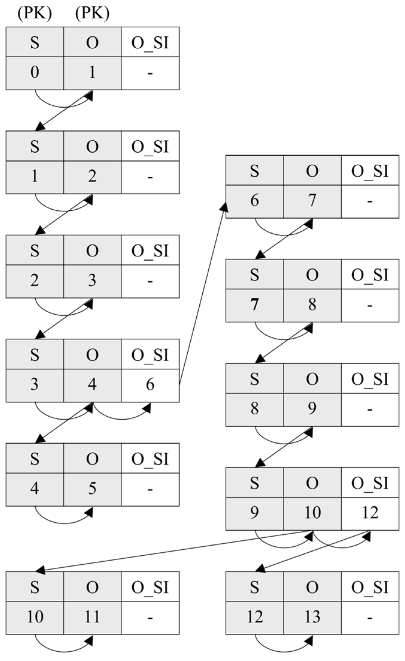
4.3. The Procedure of Topology Processing Using an Ontology Database

Figure 15 represents a subset of the lineage models stored in the ODB, with data for ‘Terminal4’ and ‘Switch4964’ represented as ‘S’, ‘P’, and ‘O’. RDF triples can be represented in the form of an RDF graph, as shown in Figure 15, where the subject and object nodes are merged. The Terminal with the mRID ‘53002901066’ includes not only the attribute name, which belongs to the Terminal class called ‘Terminal4’, but also correlations with the Switch having mRID ‘10992901066’. Unlike an RDB, an ODB includes correlations between components within the data itself, allowing straightforward exploration of hierarchical topologies.
If an ODB is utilized, correlations between components of the power distribution system can be stored in the RDF structure, facilitating TP. The ODB can be implemented as an RDF triple store or a GDB. RDF triple store involves storing data by structuring RDB tables into RDF triples (S-P-O). A GDB, however, is a type of no-SQL database that stores RDF nodes in a graph format. An RDF triple store allows index searching, treating all the S, P, and O as primary keys. Utilizing these characteristics facilitates data indexing and efficient exploration. Each RDF triple possesses a unique address, enabling swift retrieval of desired data stored in the database through triple indexing. Therefore, the RDF triple store is advantageous for TP, and the time complexity of the RDF triple store in terms of TP can be expressed as Equation (2). This equation indicates the extent to which the processing time of topology increases relative to the amount of data given. As the number of nodes increases, the speed of TP becomes significantly faster compared to an RDB. By utilizing an RDF triple store, it is possible to efficiently process and explore large-scale RDF data. Equation (2) theoretically represents the time complexity of topology processing using an RDF triple store, which leverages the advantages of structured triple indexing. This equation is derived based on the assumption that each element—subject (S), predicate (P), and object (O)—is treated as a primary key in the triple-based index structure.
O h R D F = O n log 2 n
Table 4 shows examples of RDF triples stored in an RDF triple store. Figure 16 illustrates TP using the RDF triple store, based on the example presented in Table 4. As shown in Figure 16, the initial search involves querying records where ‘S’, ‘P’, and ‘O’ are ‘0’, ‘Terminal.ConductingEquipment’, and ‘1’, respectively. Subsequently, the next step entails searching for records where ‘S’ is ‘1’ to establish a topology connection. This involves searching for records where ‘S’ equals ‘1’ and ‘O’ equals ‘2’. This process is iterated by searching for records where ‘S’ equals ‘2’. Since S-P-Os are all treated as primary keys, they can be efficiently processed using an index search.
A GDB stores data in an RDF graph structure, allowing direct connections between data elements. A GDB is a database well suitable for handling complex operations using graph theory. It utilizes index-free adjacency, allowing swift node traversal without the necessity for index searches. Since the data are directly connected in a graph structure, the speed of TP is significantly faster. This structure allows for a clear representation of relationships between data and facilitates easy comprehension of complex relationships. In the RDF graph structure, each node represents an entity, and each edge represents a relationship between entities. Through this data structure, it is possible to explore connected nodes starting from a specific node. By exploring each node and its connected nodes, one can efficiently and rapidly find the desired information. Equation (3) describes the optimal traversal performance of a GDB, which is based on index-free adjacency. These characteristics are advantageous for TP, and the time complexity in this case can be expressed as follows:
O h G D B = O n
The GDB demonstrates exceptional performance in handling large-scale interconnected data environments. This is attributed to its graph structure, which effectively represents data relationships and allows for efficient exploration. Figure 17 illustrates an example of TP using a GDB. As shown in Figure 17, it can be observed that the ‘Terminal.ConductingEquipment’ of ‘0’ is ‘1’ and the ‘ConductingEquipment.Terminal’ of ‘1’ is ‘2’. The topology can be easily explored by iterating through this process. Starting from ‘0’, one can sequentially explore ‘S’, ‘P’, and ‘O’ in the order of ‘1’, ‘2’, and ‘3’ to find the next node.
An RDB restricts index searches solely to primary keys, resulting in sluggish topology searches. On the contrary, an RDF triple store utilizes each triple (S, P, and O) as a primary key, and a GDB leverages the correlations of the RDF graph format, leading to rapid TP. Comparatively, the complexity of the system search varies; an RDB has a complexity of O n 2 , while an RDF triple store and a GDB exhibit the complexities of O n log 2 n and O n , respectively. As the number of nodes increases, the time complexity of an RDB increases rapidly, resulting in poor topology processing performance. Equations (1)–(3) are theoretically derived to characterize the data traversal behavior of each database type in the context of TP within DMS platforms. These results will contribute to a more rigorous evaluation of system scalability and reliability under practical conditions.
Although ODBs rely on semantic inference and graph-based processing, which may raise concerns about computational cost and slower query execution compared to traditional RDBs, this limitation is mitigated in the context of DMSs. Since power systems are inherently modeled as graph structures for topology-based applications such as load flow, fault detection, and network switching, the graph-oriented nature of ODBs provides structural alignment with DMS data models. In particular, the use of GDBs with index-free adjacency significantly enhances traversal speed without requiring complex join operations. Furthermore, semantic reasoning can be limited to offline or non-real-time processing tasks, enabling efficient and lightweight topology processing in real-time applications. This compatibility between domain structure and database design contributes to maintaining system performance while leveraging the flexibility and extensibility of ontology-based frameworks.
The proposed framework supports scalability for large-scale real-time DMS platforms by leveraging the graph-based and schema-flexible properties of ODBs. In the case study, topology processing performance was evaluated using actual operational data from KEPCO’s headquarters-level DMS. The system supports between 156 and 629 feeders per headquarters, depending on the region, validating the proposed framework’s effectiveness in high-complexity, real-time conditions. This scalability is demonstrated through the case study results in Section 5.2 (Areas A, B, and C).

5. Case Studies

To verify the effectiveness of the proposed approach for applying an ODB into a DMS, various case studies were conducted. This paper compared the processing speed of TP when employing an RDB and an ODB to verify the feasibility of the proposed framework. A test platform in Figure 18 was developed for conducting case studies, comprising middleware, data agent, application, and database components. Middleware facilitates the transfer of the payload generated by the data agent to the application. The data agent receives data from the database, creates a payload, and transmits it to the middleware. The application then processes the topology using the payload as input. The results of the case studies were compared using an RDB, an RDF triple store, and a GDB. MSSQL, Apache Jena SDB, and Neo4j were employed to perform research on the RDB, the RDF triple stores, and the GDB, respectively. The computer simulations were executed on a server equipped with an i7-8700k CPU, 16 GB RAM, and an NVIDIA GeForce GTX560 graphics card, operating on the Windows 10 64-bit operating system.

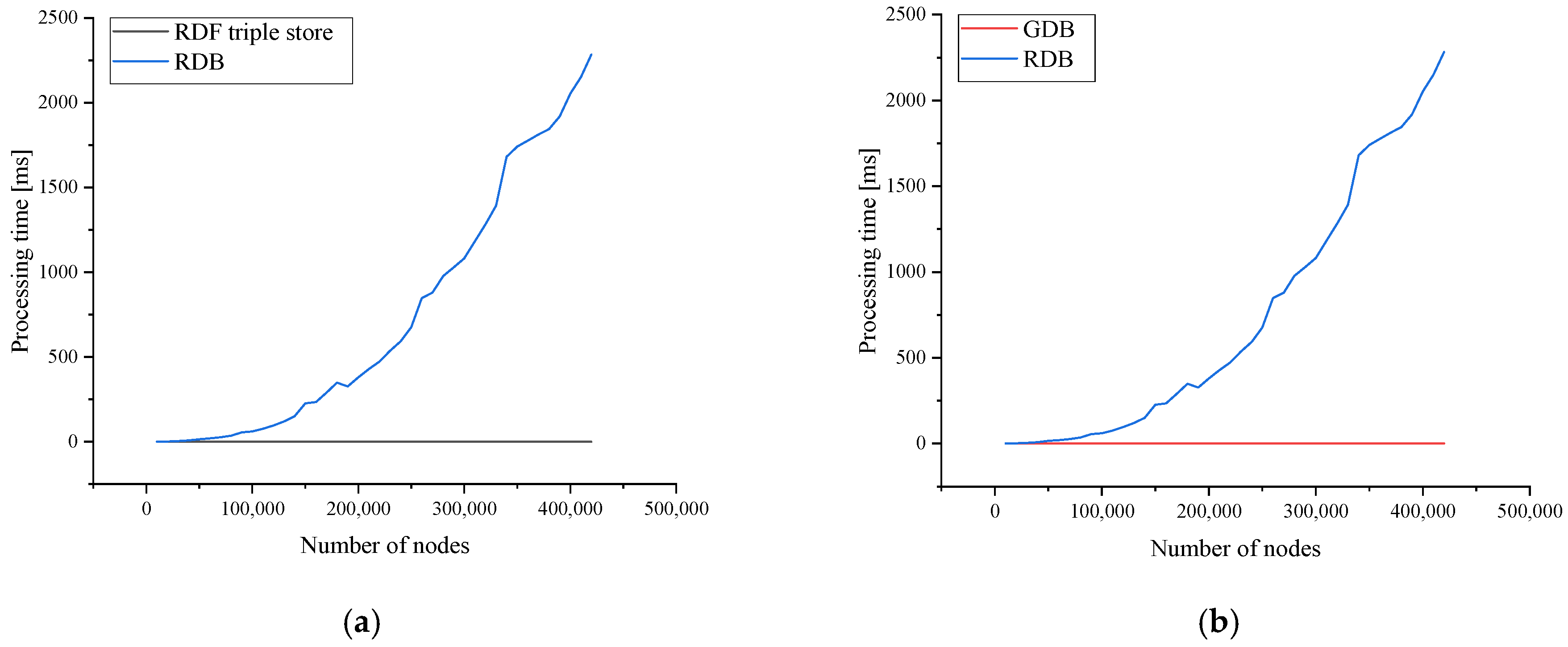
5.1. Comparison of Topology Processing Time by the Number of Nodes

Table 5 depicts the distribution network layout of the ‘area A’ of KEPCO, used for case studies. As shown in Table 5, there are 441,284 Terminals, 164,222 ConnectivityNodes, and 269,268 ConductingEquipments. The class inheriting from ConductingEquipment includes EnergySource, EnergyConsumer, Switch, Junction, LineSegment, PowerTransformer, and BusBarSection. EnergySource class is used to model distributed power generation, while EnergyConsumer class is chosen to represent loads. The Switch class is used to indicate all switches used by KEPCO, including automatic and manual switches, automatic load transfer switches, and composite switches. Line section information is represented by using the ACLineSegment class, while bus information within a substation is modeled by using BusBarSection class. Additionally, the PowerTransformer class is used to model the power transformer within a substation, and the step voltage regulator is utilized on distribution lines.
Figure 19 and Figure 20 depict the graphs illustrating the TP time for each database as the number of target system nodes in the DMS increases. Figure 19 compares the TP time of the RDB and the ODB, while Figure 20 compares the TP time of the RDF triple store and the GDB within the ODB. As shown in Figure 19 and Figure 20, the TP time of the RDB escalates rapidly compared to the ODB using both the RDF triple store and GDB as the number of nodes increases. Table 6 shows the exploration time of the topology based on the number of nodes. When there are 10,000 terminals, the exploration speed of the RDF triple store is approximately 186 times faster compared to the RDB, while the GDB is approximately 557 times faster. However, with 400,000 terminals, the exploration speed of the RDF triple store is approximately 19,745 times faster than that of the RDB, while the GDB is approximately 73,340 times faster. As the number of nodes increases, the impact on the speed of TP becomes more pronounced. Therefore, through a case study, it is demonstrated that applying an ODB is more advantageous for large-scale systems, although several CIM-based commercial products utilizing RDBs with highly sophisticated SQL queries can significantly enhance TP performance.

5.2. Expansion to Three Distribution Networks of the Republic of Korea

To expand the applicability of the proposed approach, the validity of the proposed approach for applying an ODB, as presented in this study, is verified by using three distribution networks of the Republic of Korea, areas A, B, and C. A comparative analysis is conducted on the TP performance across KEPCO’s three distribution networks. The time taken to receive input data from the RDB, the RDF triple store, and the GDB through the data agent and middleware, and to generate a payload in the application is measured. Table 7 shows the number of nodes for each component of the distribution system managed by each area of the Republic of Korea. As shown in Table 7, the total number of nodes managed by areas A, B, and C is 874,774, 524,748, and 220,450, respectively, with area A overseeing the highest number of nodes.
Table 8 represents the TP speeds when applying the RDB and the ODB to their respective target systems. As shown in Table 8, the exploration speed of the RDB compared to the ODB increases rapidly as the number of nodes in the target system increases. This demonstrates the advantage of employing the ODB in larger systems. The exploration time for the RDB ranges from a maximum of 2283 [ms] to a minimum of 82 [ms]. It is evident that the performance of TP in the ODB improves in comparison to the RDB as the number of nodes managed by the areas increases. Area A finds that the TP speed of the RDF triple store is approximately 20,210 times faster than that of the RDB, while the GDB is approximately 78,749 times faster. Similarly, for area B, querying the RDF triple store is approximately 9846 times faster than the RDB, while the GDB is approximately 39,383 times faster. For area C, the exploration speed of the RDF triple store is approximately 3452 times faster than that of the RDB, while the GDB is approximately 11,834 times faster. As the number of nodes managed by the DMS increases, the difference in TP speed between RDB and ODB applications becomes more pronounced.

6. Conclusions

This paper proposed a CIM-based framework that applies an ODB to a DMS to enhance interoperability and improve TP performance. By employing the RDF-based, schema-flexible structure of the ODB, the proposed approach effectively addresses three key limitations of traditional RDBs: object–relational impedance mismatch, inflexibility to accommodate information model changes, and performance degradation in TP. Objects modeled in the CIM format can be directly stored as RDF triples or graph structures within the ODB, enabling seamless object-to-database mapping. This eliminates the need for transformation processes and enhances data consistency and query efficiency. The ODB also enables knowledge inference through RDF reasoning capabilities, and it provides a flexible interface for data import/export in CIM/RDF/XML formats. The proposed approach has been validated through case studies using actual DMS operational data from the Republic of Korea, demonstrating its practical viability in a real-world environment. Furthermore, standardized interfaces across all DMS components—including the ODB—facilitate seamless system integration and pave the way for the development of a knowledge inference engine based on ODBs.
Although this study is based on Korea’s DMS environment, the proposed framework is applicable to other countries that adopt IEC CIM standards, supporting international interoperability and platform scalability. This work builds upon the authors’ previous research on CIM extension, RDF-based data handling, and ontology system integration for power grid applications. Future studies will explore international case studies and cross-country implementation scenarios to validate the adaptability of the proposed framework in various regulatory and operational contexts. The proposed framework supports policy-driven requirements for interoperability, transparency, and modular system integration. By aligning with globally recognized standards such as IEC 61970/61968, it lays a foundation for future regulatory compliance and cross-border energy system harmonization.
Despite the benefits of the proposed framework, current limitations include the need for manual ontology modeling and instance mapping. Future work will focus on developing semi-automated tools to alleviate this burden and further enhance the scalability and usability of the framework.

Author Contributions

Conceptualization, J.H. and Y.-S.O.; methodology, J.H.; software, J.H. and S.-A.S.; validation, J.-U.S., Y.-S.O. and S.-I.L.; formal analysis, J.H. and Y.-S.O.; investigation, S.-A.S. and G.-H.K.; resources, S.-A.S.; data curation, J.-U.S.; writing—original draft preparation, J.H.; writing—review and editing, Y.-S.O.; visualization, J.H.; supervision, S.-I.L.; project administration, G.-H.K.; funding acquisition, G.-H.K. All authors have read and agreed to the published version of the manuscript.

Funding

This research was supported by Korea Electrotechnology Research Institute (KERI) Primary research program through the National Research Council of Science & Technology (NST) funded by the Ministry of Science and ICT (MSIT) (No. 25A01025).

Institutional Review Board Statement

Not applicable.

Informed Consent Statement

Not applicable.

Data Availability Statement

The original contributions presented in the study are included in the article, further inquiries can be directed to the corresponding author.

Conflicts of Interest

The authors declare no conflicts of interest.

Abbreviations

The following abbreviations are used in this manuscript:
DMSdistribution management system
DERdistributed energy resource
TPtopology processing
ODBontology database
RDBrelational database
CIMcommon information model
EVelectric vehicle
MVDCmedium-voltage direct current
DSOdistribution system operator
IECInternational Electrotechnical Commission
TCTechnical Committee
EMSenergy management systems
TSOtransmission system operator
ICTinformation and communication technology
ORMobject–relational mapping
ORDBobject–relational database
GDBgraph database
MDDmodel-driven development
CBDcomponent-based development
CCAPIcontrol center API
UMLunified modeling language
FEPfront-end processor
HMIhuman–machine interface
FLISRfault location, isolation, and service restoration
EAEnterprise Architect
SOPsoft-open point
OWLweb ontology language
PIMPlatform-Independent Model
PSMPlatform-Specific Model
RDFSRDF Schema
XSDXML Schema
IDLInterface Definition Language

References

  1. Asmus, P.; Lawrence, M.; Metz, A.; Gunjan, P.; Labastida, R.R.; Shepard, S.; Woods, E. Integrated DER: Orchestrating the Grid’s Last Mile; Guide House: McLean, VA, USA, 2020. [Google Scholar]
  2. Navigant Research. Optimization DER Integration & Grid Management with ADMS and DERMS. 2019.
  3. Ministry of Trade, Industry, and Energy. The 10th Basic Plan of Long-Term Electricity Supply and Demand. 2023. Available online: https://nsp.nanet.go.kr/plan/subject/detail.do?nationalPlanControlNo=PLAN0000033810 (accessed on 30 March 2025).
  4. Government of the Republic of Korea. 2050 Long-Term Low Greenhouse Gas Emission Development Strategies (LEDS) Carbon Neutral Strategy of the Republic of Korea: Towards a Sustainable and Green Society. 2020. Available online: https://unfccc.int/documents/267683 (accessed on 30 March 2025).
  5. The Number of EV Chargers Exceeds 70,000… Concerns Over Shortage as EVs Reach 230,000 Units. Available online: https://www.mk.co.kr/news/society/10299536 (accessed on 30 March 2025).
  6. Ministry of Trade, Industry, and Energy. The 4th Energy Technology Development Plan (2019~2028). 2019. Available online: https://www.korea.kr/archive/expDocView.do?docId=39159 (accessed on 30 March 2025).
  7. IEC 61970-301; International Standard: Energy Management System Application Program Interface (EMS-API)—Part 301: Common Information Model (CIM) Base. IEC Standards: Geneva, Switzerland, 2022.
  8. IEC 61968-1; International Standard: Application Integration at Electric Utilities—System Interfaces for distribution Management—Part 1: Interface Architecture and General Recommendations. IEC Standards: Geneva, Switzerland, 2020.
  9. IEC 62325-301; International Standard: Framework for Energy Market Communications—Part 301: Common Information Model (CIM) Extensions for Markets. IEC Standards: Geneva, Switzerland, 2018.
  10. Worighi, I.; Maach, A.; Hafid, A.; Hegazy, O.; Mierlo, J.V. Integrating renewable energy in smart grid system: Architecture, virtualization and analysis. Sustain. Energy Grids Netw. 2019, 18, 100226. [Google Scholar] [CrossRef]
  11. Shen, F.; López, J.C.; Wu, Q.; Rider, M.J.; Lu, T.; Hatziargyriou, N.D. Distributed self-healing scheme for unbalanced electrical distribution systems based on alternating direction method of multipliers. IEEE Trans. Power Syst. 2020, 35, 2190–2199. [Google Scholar] [CrossRef]
  12. Jabr, R.A.; Džafić, I. Distribution Management Systems for Smart Grid: Architecture, Work Flows, and Interoperability. J. Mod. Power Syst. Clean Energy 2022, 10, 300–308. [Google Scholar] [CrossRef]
  13. Melton, R.B.; Schneider, K.P.; Lightner, E.; Mcdermott, T.E.; Sharma, P.; Zhang, Y.; Ding, F.; Vadari, S.; Podmore, R.; Dubey, A.; et al. Leveraging standards to create an open platform for the development of advanced distribution applications. IEEE Access 2018, 6, 37361–37370. [Google Scholar] [CrossRef]
  14. Melton, R.B.; Schneider, K.P.; Vadari, S. GridAPPS-DTM a distribution management platform to develop applications for rural electric utilities. In Proceedings of the IEEE Rural Electric Power Conference (REPC), Bloomington, MN, USA, 28 April–1 May 2019. [Google Scholar] [CrossRef]
  15. Anderson, A.; Barr, J.; Vadari, S.; Dubey, A. Real-time distribution simulation and application development for power systems education. In Proceedings of the IEEE Power & Energy Society General Meeting (PESGM), Denver, CO, USA, 17–21 July 2022. [Google Scholar] [CrossRef]
  16. Sharma, P.; Reiman, A.P.; Anderson, A.A.; Poudel, S.; Allwardt, C.H.; Fisher, A.R.; Slay, T.E.; Mukherjee, M.; Dubey, A.; Ogle, J.P.; et al. GridAPPS-D Distributed App Architecture and API for Modular and Distributed Grid Operations. IEEE Access 2024, 12, 39862–39875. [Google Scholar] [CrossRef]
  17. Poudel, S.; Sharma, P.; Dubey, A.; Schneider, K.P. Advanced FLISR with intentional islanding operations in an ADMS environment using GridAPPS-D. IEEE Access 2020, 8, 113766–113778. [Google Scholar] [CrossRef]
  18. Anderson, A.A.; Podmore, R.; Sharma, P.; Reiman, A.P.; Jinsiwale, R.A.; Allwardt, C.H.; Black, G.D. Distributed application architecture and LinkNet topology processor for distribution networks using the common information model. IEEE Access 2022, 10, 120765–120780. [Google Scholar] [CrossRef]
  19. Soares, T.; Carvalho, L.; Morais, H.; Bessa, R.J.; Abreu, T.; Lambert, E. Reactive power provision by the DSO to the TSO considering renewable energy sources uncertainty. Sustain. Energy Grids Netw. 2020, 22, 100333. [Google Scholar] [CrossRef]
  20. Uslar, M.; Rohjans, S.; Neureiter, C.; Andrén, F.P.; Velasquez, J.; Steinbrink, C.; Efthymiou, V.; Migliavacca, G.; Horsmanheimo, S.; Brunner, H.; et al. Applying the smart grid architecture model for designing and validating system-of-systems in the power and energy domain: A european perspective. Energies 2019, 12, 258. [Google Scholar] [CrossRef]
  21. Robinson, I.; Webber, J.; Eifrem, E. Graph Databases; OReilly Media Inc.: Newton, MA, USA, 2013. [Google Scholar]
  22. McDermott, T.E.; Stephan, E.G.; Gibson, T.D. Alternative database designs for the distribution common information model. In Proceedings of the IEEE/PES Transmission and Distribution Conference and Exposition (T&D), Denver, CO, USA, 16–19 April 2018. [Google Scholar] [CrossRef]
  23. Wu, J.; Schulz, N.N. Overview of CIM-oriented database design and data exchanging in power system applications. In Proceedings of the 37th Annual North American Power Symposium, Ames, IA, USA, 25 October 2005. [Google Scholar] [CrossRef]
  24. Barros, J.V.; Leite, J.B. Development of a relational database oriented on the common information model for power distribution networks. In Proceedings of the IEEE URUCON, Montevideo, Uruguay, 24–26 November 2021. [Google Scholar] [CrossRef]
  25. Ravikumar, G.; Khaparde, S.A.; Pradeep, Y. CIM oriented database for topology processing and integration of power system applications. In Proceedings of the IEEE Power & Energy Society General Meeting, Vancouver, BC, Canada, 21–25 July 2013. [Google Scholar] [CrossRef]
  26. Elbattah, M.; Roushdy, M.; Aref, M.; Salem, A.M. Large-scale ontology storage and query using graph database-oriented approach: The case of freebase. In Proceedings of the IEEE Seventh International Conference on Intelligent Computing and Information Systems, Cairo, Egypt, 12–14 December 2015. [Google Scholar] [CrossRef]
  27. Ravikumar, G.; Khaparde, S.A. A common information model oriented graph database framework for power systems. IEEE Trans. Power Syst. 2017, 32, 2560–2569. [Google Scholar] [CrossRef]
  28. EPRI. CIM Primer, 8th ed.; EPRI: Palo Alto, CA, USA, 2022. [Google Scholar]
  29. Hwang, J.; Oh, Y.; Song, J.; An, J.; Jeon, J. Development of a platform for securing interoperability between components in a carbon-free island microgrid energy management system. Energies 2021, 14, 8525. [Google Scholar] [CrossRef]
  30. Beydeda, S.; Book, M.; Gruhn, V. Model-Driven Software Development; Springer: Berlin/Heidelberg, Germany, 2007. [Google Scholar]
  31. Panic, S.; Petrovic, V.; Kontrec, N.; Milojevic, S. Performance analysis of hybrid FSO/RF communication system with receive diversity in the presence of chi-square/gamma turbulence and rician fading. Univ. Kragujev. Digit. Arch. 2023, 4, 304–313. [Google Scholar] [CrossRef]
Figure 1. UML diagram for a profile regarding network topology.
Applsci 15 04105 g001
Figure 2. Transformation of a distribution network model into a CIM.
Applsci 15 04105 g002
Figure 3. General platform architecture of the CIM-based DMS.
Applsci 15 04105 g003
Figure 4. An example of object–relational impedance mismatch.
Applsci 15 04105 g004
Figure 5. An example of the RDB schema design for objects: (a) class tabulation; (b) object tabulation.
Applsci 15 04105 g005
Figure 6. Change in the information model due to new requirements on the power industry business: (a) deletion; (b) addition and update.
Applsci 15 04105 g006
Figure 7. Types of information model modification.
Applsci 15 04105 g007
Figure 8. RDB schema design for topology processing.
Applsci 15 04105 g008
Figure 9. An example of topology processing using data in an RDB.
Applsci 15 04105 g009
Figure 10. CIM-oriented DMS development based on MDD and CBD methodologies.
Applsci 15 04105 g010
Figure 11. CIM-oriented DMS using ontology database architecture.
Applsci 15 04105 g011
Figure 12. An example of storing an interface schema in an ontology database.
Applsci 15 04105 g012
Figure 13. An example of storing payload data in an ontology database.
Applsci 15 04105 g013
Figure 14. An example of generating a payload using an interface schema.
Applsci 15 04105 g014
Figure 15. Joining RDF triples.
Applsci 15 04105 g015
Figure 16. Topology processing using an RDF triple store.
Applsci 15 04105 g016
Figure 17. Topology processing using a graph database.
Applsci 15 04105 g017
Figure 18. Configuration of the test platform.
Applsci 15 04105 g018
Figure 19. Topology processing time comparison: (a) RDF triple store and RDB; (b) GDB and RDB.
Applsci 15 04105 g019
Figure 20. Topology processing time of the RDF triple store and GDB.
Applsci 15 04105 g020
Table 1. Summary of representative research works on CIM-based DMS platforms and database approaches.
Ref. No.Key ContributionStrengthsLimitations
[10,11]Introduction of communication standards and CIM for data modelingProvides a foundational understanding of CIMLacks practical implementation aspects
[12]Application of CIM-based interoperability in smart grid DMSEmphasizes integration importance in advanced DMSDoes not focus on data storage or performance
[13,14,15,16]Development of GridAPPS-D, a CIM-based open platformEnables advanced DMS application development and reuseMainly focused on application logic, not database performance
[17,18]Implementation of new CIM-based advanced DMS applicationsDemonstrates the practical utility of CIMNo analysis on data processing efficiency
[19,20]TDX-ASSIST project for TSO–DSO CIM-based data exchangeExtends CIM interoperability across system boundariesNot directly related to real-time DMS database design
[21,22]Issues of using RDB with CIM: object–relational mismatchMaintains reliability and structure in legacy systemsSchema rigidity, low TP performance, complex queries
[23,24]Analysis of TP performance degradation in CIM-based RDBsHighlights the need for flexible modelingLimited ability for topological search and model updates
[25]Proposal of CIM-based ORDB with ORM toolsBridges object–relational paradigmORM-related complexity, optimization limitations
[26,27]GDB-based framework for storing large-scale CIM ontologiesSuitable for semantic modeling and scalabilityLacks real-time DMS implementation or TP focus
Table 2. Overview of CIM-Based Standards.
StandardApplication DomainDescription
IEC 61970Transmission SystemsDefines the CIM for energy management system (EMS) integration and information exchange.
IEC 61968Distribution SystemsSupports data exchange between distribution management systems (DMS) and other utility applications.
IEC 62325Electricity MarketsProvides models and messages for electricity market communications based on CIM.
Table 3. Structural modification of an RDB due to changes in information models.
Modification of Information ModelsClass TabulationObject Tabulation
Changeclass nametable nametable name (depending on the case)
attribute namefield namefield name
correlation between classeschangeNot changed
Deleteclasstable (deleting the inheritance relationship and foreign key relationship between tables)table or related field (depending on the case)
attributefieldfield
correlation between classesforeign key relationship between tablesforeign key relationship between tables (depending on the case)
Addsubclass/superclasstable and set a foreign key relationshiprelated table or field (depending on the case)
attributefieldfield
correlation between classesforeign key relationshipfield of inheritance relationship; otherwise, foreign key relationship
Table 4. Comparison of Binary Tree, B−Tree, and B+Tree.
CategoryBinary TreeB−TreeB+Tree
Number of child nodesUp to 2 child nodesMultiple child nodes
(the number can be defined)
Multiple child nodes
(the number can be defined)
Data storage locationKey and value are stored at the nodeKey and value are stored at both the internal and leaf nodesOnly the key is stored at the internal node, and the actual data are stored at the leaf node
Index
structure
  • Data are searched based on the key
  • Data search, insert, and deletion are efficient
  • This index structure is mainly used in large DBs or file systems
  • Data search and range search are supported by storing keys and values at both the internal and leaf nodes
  • This structure is widely used in a large DB system.
  • Efficient for range search and sequential access
Table 5. Number of nodes within the test distribution network.
CIM ObjectNumber of Nodes
Terminal441,284
ConnectivityNode164,222
ConductingEquipmentEnergySource13,992
EnergyConsumer9110
Switch58,113
Junction64,994
ACLineSegment122,561
PowerTransformer176
BusBarSection322
Total ConductingEquipment269,268
Total CIM Objects874,774
Table 6. Topology processing time according to the number of nodes.
Number of TerminalsRDB [ms]RDF Triple Store [ms]GDB [ms]
10,0000.5570.0030.001
100,00060.2000.0220.005
200,000379.2380.0440.014
300,0001081.5620.0780.021
400,0002053.5100.1040.028
Table 7. Number of network nodes for three areas in the Republic of Korea.
AreaTerminalConnectivity NodeConducting EquipmentTotal Objects
A441,284164,222269,268874,774
B265,98195,544163,223524,748
C112,20539,84968,396220,450
Table 8. Topology processing time for three areas in the Republic of Korea.
AreaRDB [ms]RDF Triple Store [ms]GDB [ms]
A2283.7250.1130.029
B707.8890.0720.018
C82.8400.0240.007
Disclaimer/Publisher’s Note: The statements, opinions and data contained in all publications are solely those of the individual author(s) and contributor(s) and not of MDPI and/or the editor(s). MDPI and/or the editor(s) disclaim responsibility for any injury to people or property resulting from any ideas, methods, instructions or products referred to in the content.

