1. Introduction
Smart distribution grids are a promising technology to integrate low emission and renewable energy resources with the power grid. Recently, smart distribution grids have been developed to supply end users with not only electric energy but also heating and cooling in a smart, high-efficiency, environmentally friendly system. The energy flows between the electric, thermal, and cooling systems in a cooperative CCHP framework to reduce the emission of greenhouse gases and increase the entire system’s energy efficiency with a reduction in total operating cost. The interaction between these systems leads to an increase in the complexity of the operation.
The optimal operation of the CCHP achieves significant benefits for both the environment and the system operators. Therefore, many sophisticated and intelligent algorithms have been developed to model and analyze the optimal operation of the CCHP system. Many researchers address different optimization approaches to minimize the operating cost of multicarrier systems. In ref. [
1,
2,
3,
4,
5,
6,
7,
8,
9,
10], authors proposed EMS to minimize the total operation cost of systems which supply electric and heat power (CHP). However, the cooling system is not taken into consideration in the approaches proposed in these papers.
Authors in reference [
11] proposed optimal operation planning of CCHP with the integration of renewable energy. Different cases with and without renewable energy are conducted to evaluate the impacts of wind and solar energy on the optimal operation of the CCHP system. The results showed that the performance of CCHP integrated with either photovoltaic panels or solar collectors is much better than CCHP integrated with photovoltaic thermal solar collectors. A day-ahead optimal planning of the CCHP system with integration of renewable energy resources was presented in [
12,
13]. It was found that employing the storage energy device reduces the cost. Authors in reference [
14] proposed an EMS of the CCHP system to minimize the operating cost and keep the risk at a permissible level, while reference [
15] presented an EMS to minimize the operation cost of the CCHP system with consideration of renewable energy. Reference [
16] suggested optimal planning to reduce the operating cost with the integration of renewable energy where the results revealed that the proposed approach improves the system’s energy efficiency.
References [
11,
12,
13,
14,
15,
16] minimized the operating cost only, and they ignored the environmental damage cost in their proposed approaches. In addition, unit commitment was not taken into account in their analysis. Further, many realistic constraints were overridden, and they managed only the generation side and did not consider the management of consumption of end users.
Reference [
17] presented the optimization approach of CCHP with the integration of electric vehicles (EVs) as an electric source. The result reveals that the integration of EVs increases the benefits compared to EVs. The proposed optimization algorithm of the CCHP system is either to minimize the operating cost or emission of greenhouse gases (GHGs) in the trading-off approach due to conflict between two objective functions. The simulation results showed the effectiveness of the proposed approach to improve the system efficiency and reduction of greenhouse gases. The author in reference [
18] demonstrated a multi-objective optimal operation to reduce the total expense of the operation. However, in [
17,
18] the proposed analysis is modelled as a multi-objective model, and the compromise Pareto solution set of nondominated solutions is obtained. However, this method is a tradeoff method; there is not any single optimal solution, and it is not suitable for online operation. Furthermore, the demand response is ignored in this approach. The exchange in energy with the utility grid is overridden in this model. Reference [
19] proposed an optimal planning of CCHP with the integration of electric vehicles as new energy sources to reduce the cost of operation. Different scenarios have been conducted depending on the variable of consumer consumption during different seasons. The proposed model overrides the emission cost and demand side in their approach, and many constraints and unit commitments are not considered in the proposed approach.
References [
20,
21,
22,
23] suggested optimal planning to reduce the cost of fuel consumption under uncertainty of renewable energy generation and load by employing a two-stage approach. The first stage is the day-ahead economic schedule, and the second stage is a correction stage of sustainable energy resource generation and load prediction. All references do not take into consideration the emission cost and demand side response. This paper takes into consideration the demand response mechanism, energy storage devices, and exchange in energy with the utility grid with the flexibility of operation of CCHP system devices by transforming energy from one form to another to mitigate the fluctuation in the renewable energy resources and loads variability. In addition, the robustness of the system is improved without excessive expense.
Authors in [
24,
25,
26] presented an optimization approach to minimize the operating cost of CCHP based on an energy hub. However, these papers ignored the emission cost and demand side management from their formulation of the optimization problem and many realistic constraints. Additionally, the unit commitment technique is not considered in their model.
The optimal planning of both the generation and demand sides is an important technique to tackle the impacts of the intermittence of renewable energy generation. Accordingly, many researchers proposed the optimization approach of smart grid with integration of demand side management [
27,
28,
29,
30,
31,
32]. However, these studies proposed the optimization problem with demand-side management of single carrier microgrids without considering heating and cooling systems. Few researchers suggested an optimal operation of CCHP with demand response [
12,
33]. However, reference [
33] ignored the environmental cost, UC strategy, renewable energy, gas boiler, and chillers models in their proposed model. Furthermore, the demand response is not considered a decision variable in the optimization problem. Reference [
12] overrides the environmental cost, startup and shutdown cost of generators, UC strategy, ramp rate constraints, and constraints relevant to environmental damage.
In this paper, a novel UC optimal operation of CCHP with the integration of demand response and renewable energy sources is proposed to minimize both the total running and environmental costs, where the DR program is considered as a decision variable in the optimization problem. Additionally, a set of realistic constraints is taken into account in the proposed model to make the problem close to a real scenario. The UC technique and the constraints are developed to respond to the interaction between electric, heating, and cooling systems to achieve optimal operation. Further, the ramp rate constraints are considered not only for generators but also for GB and AC. The proposed optimization problem aims to minimize both the operating cost and emission level of the GHGs. These functions are conflicted. Therefore, the emission level of the GHGs is converted to expense, and the two-objective optimization problem is converted to a unified problem that can be solved and a single solution is obtained, which is suitable for real-time operation. Two scenarios are conducted with and without demand response to achieve the aim of this paper.
2. Mathematical Model of the Components of the Proposed System
It is important to model all components of the proposed system as accurately as possible to formulate the optimization problem. The following are the mathematical models of each component of the proposed system.
2.1. Electric Subsystem
The electric grid includes the following devices, where each one is modelled to incorporate with the optimization approach.
2.1.1. MT-Based CHP Model
MT-based CHP is considered in this paper to supply electric and heat energy simultaneously. Micro-turbines are fueled by NG. The consumed gas is determined by employing the following equation [
33,
34,
35]:
where
is the produced electric power of the MT (kW),
is the low heating value (LHV) of the NG (kWh/m
3),
is the efficiency of MT, and
is the on/off case of the MT.
The CHP generates heat power in addition to electric energy, where the produced heat power is depicted in the following equation:
where
is the heat loss factor of the MT and
is the efficiency of heat recovery. The expense of the NG consumed by the MT is determined as follows:
where
is the price of NG (EUR/m
3).
2.1.2. Fuel Cell
The following formula is employed to determine the fuel consumption of the FC [
33,
34]:
where
is the production power of the FC (kW), and
is the on/off case of the FC. The running cost of the FC is as follows:
2.1.3. Diesel Generator
The fuel consumption of the DE is calculated from the equation below [
7]:
where
and
are the coefficients of the cost function and
is the on/off state of the DG at each time interval.
2.1.4. Energy Storage Battery
The following equation governs the operation of the SB [
36]:
where
and
are the level of the SB charge at time
and
, respectively.
and
are the delivering and absorbing power.
and
are the efficiencies. ∆t is the time interval of operation. The expense of the SB operation is calculated as follows:
where
is the operation expense of the SB (EUR/kWh).
2.1.5. Exchanging Electric Energy with the Utility Grid
The CCHP system can trade energy with the main system, and this cost is formulated as follows:
where
is the exchange of power with the main grid. It takes either positive for buying power or negative for selling power.
is the electric energy open market price (EEOMP) (EUR/kWh).
2.1.6. On/Off Costs of the DGs
These costs are formulated using the following equations [
7,
34]:
where
and
are the costs of frequent on/off of the
th DG (EUR/kWh).
2.1.7. Emission Cost
The emission of carbon dioxides CO
2, Sulphur dioxides SO
2, nitrogen oxides NO
x, and particulate matter PM causes damage to the environment and pollutes the weather. These are converted to expenses using the following formula:
where
(EUR/kg) is the price for emission of the jth greenhouse gas, and
(kg/kWh) is the level of the emission of the jth GHGs due to the operation of the
th DG. N and K are the number of DGs and GHGs, respectively.
2.1.8. Operation and Maintenance Expense of DGs
where
(EUR/kWh) is the coefficient of operating and maintenance cost of the
th DG.
2.2. Heat Subsystem
The model of each component of the heat system is listed as follows:
2.2.1. Gas Boiler Operating Model
The GB consumes fuel during its operation. This expense of consuming fuel is expressed as follows:
where
is the produced heat from the GB and
is the efficiency of the GB. The running cost of consuming NG is as follows:
2.2.2. Electric Heater Model
The EH converts electric energy to heat energy to supply the heat load, where the equation describes the expense of operation as follows:
where
is the consumed electric power, and
is the efficiency of the EH.
2.2.3. Heat Storage Model
The HS operation is expressed by the following formula [
34]:
where
and
are heat levels stored in the HS at
and
and
heat are power delivered of or absorbed from the HS (kW).
is the heat loss rate.
2.2.4. Exchanging Heat Energy with the Main System
Heat energy can be exchanged with the main grid, and the expense of these operations is expressed by the following equation:
where
is the exchange of heat power with the main grid. It takes either positive for buying power or negative for selling power. The
is the heat energy open market price (HEOPM)(EUR/kWh).
2.2.5. The Operating and Maintenance Cost of the GB
2.2.6. The Operating and Maintenance Cost of the EH
where
and
(EUR/kWh) are the coefficients of maintenance cost of the GB and EH.
2.3. Cooling Subsystem
The model of each component of the cooling system is listed as follows:
2.3.1. Electric Chiller Operation Model
The EH supplies a cooling load by converting electric energy to cooling energy. The supplied cooling energy of the EC is expressed as follows:
where
is the supplied electric power to the EC and
is the coefficient of performance.
2.3.2. Absorption Chiller Model
The AC provides cooling energy by utilizing the heat energy which is supplied by the heating system. The following equation determines the supplied power from the AC:
where
is supplied heat to the AC and
is the coefficient of performance.
2.3.3. The Operating and Maintenance Cost of EC
2.3.4. The Operating and Maintenance Cost of AC
where
and
(EUR/kWh) are the coefficients of maintenance cost of the EC and AC.
3. Proposed Model of Demand Response
The DR technique is applied to the electric load to change the load pattern of power consumption and shift the peak load to the off-peak hours. The max load is shaved and shifted to off-peak hours and is performed using a DR program, where the DR program is considered as a decision variable in the optimization problem.
The aim of this technique is to shave the max load and limit it to a specific value, where the cutting load is shifted from peak to off-peak hours consumption. The following equations are considered to perform the DR program.
where
is the hours,
is the percentage of the cutting load during the high load hours and supplied again during off-peak hours,
is the number of off-peak hours (h),
is the base load (kW),
is the final modified load,
is the peak load, and
is the set of on-peak hours during which the energy is reduced.
The peak shaving parameters affect the performance and results of the DR program, and this is reflected in the results of the optimizing approach, cost value, and scheduling of the energy generation devices. Therefore, these parameters should be chosen carefully. In this study, these parameters are chosen based on operational thresholds commonly found in similar systems and supported by open literature resources.
4. Optimization Problem of the Proposed System
4.1. The Formulation of the Objective Function
The aim of this paper is to minimize the combined objectives, the total running cost, and the emission of GHGs for the proposed CCHP system while satisfying a variety of realistic constraints of the electric, heating, and cooling systems. This is achieved by optimal planning of both the generation and consumption of end users simultaneously. The interaction between electric, heating, and cooling systems allows energy to flow between these systems to drive the proposed CCHP system operation economically and environmentally friendly. Therefore, the formulation of the objective function takes into consideration the interaction between these systems. One of the effective approaches to convert the multi-objective optimization problem into a single objective function is the monetized emission of GHGs and its incorporation with operation costs in a single objective optimization approach [
37,
38]. In this study, this approach has been utilized to formulate the optimization problem of the proposed CCHP system, where the equation is 12. Additionally, considering the constraints of Equation 59 enables more control over the emission of GHGs in the area of the system. The objective function is formulated as follows:
where
is the shedding load during the high load hour which is not supplied and
is the penalty for uncovered loads (EUR/kWh).
4.2. Mathematical Model of the Constraints
The proposed multi-objective function of Equation (33) is subjected to the following constraints.
4.2.1. Energy Balance Constraints
The electric, heating, and cooling loads should be met at each time interval, where the energy balance equations are as follows:
- a.
Electric Energy Balance Constraint
where
and
are the supplied wind and solar power and
and
are the buying and selling power from/to the upstream system.
- b.
Heat Energy Balance Constraint
where
and
are the exchange in heat power with the upstream system and
is the heat load in kW.
- c.
Cooling Energy Balance Constraint
where
is the cooling load in kW.
4.2.2. The Generators Operating Constraints
- a.
Capacity Constraints
where
and
are the minimum and maximum delivered power of the
th DG.
- b.
Ramp Rate Constraint
This constraint should be satisfied at each operation period to protect the generators from damage. The following equation is utilized to integrate this constraint with the optimization problem:
where
and
are the ramp-up/down limit of the
th DG.
4.2.3. Operation Constraints of the Storage Battery
The constraints that govern the operation of the SB are as follows:
- a.
State of Charge Constraint
- b.
Charging and Discharging Power
where
and
are zero/one variables that are utilized to prevent the SB from charging and discharging at the same time.
4.2.4. The Heat Storage Constraints
These constraints are expressed using the following equations:
- a.
State of Charge Constraint
- b.
Charging and Discharging Power
where
and
are zero/one variables that are utilized to prevent the HS from charging and discharging at the same time.
4.2.5. The Gas Boiler Operation Constraints
The following constraints limit the operation of the GB. The output heat power limits and ramp rate limits are formulated as follows:
4.2.6. The Electric Heater Constraints
4.2.7. The Electric Chiller Constraints
4.2.8. The Absorption Chiller Constraints
The output power limit and ramp rate are the constraints which are considered to limit the operation of the AC. These constraints are formulated as follows:
4.2.9. Constraints of Exchanging Electric with the Main Grid
These constraints are expressed in the following formulae:
where
,
,
, and
are the maximum and minimum exchange of electric power with the main system.
and
are zero/one variables to prevent buying and selling electric power at the same moment.
4.2.10. Exchanging Heat Energy with the Utility Grid
These constraints are formulated as follows:
where
,
,
, and
are the maximum and minimum exchange of heat power with the main grid.
and
are zero/one variables to prevent buying and selling heat power at the same moment.
4.2.11. Emission Limitation
This constraint limits the emission level of the GHFs in the area of the CCHP system:
where
is the emission limitation of the
greenhouse gas from the
DG in the area of the CCHP system.
5. Solution of the Proposed Combined-Objective Function
The proposed EMS is formulated as a combined-objective UCIMIQP. This combined-objective optimization function is converted to a single function that can be solved directly in one step [
37,
38]. General algebraic modelling system (Gams) software is employed to formulate and model the proposed optimization problem. Gams is a highly mathematical modelling system for modelling and solving optimization problems. Cplex Solver is utilized to solve the proposed CCHP optimization problem. CPLEX is an efficient solver, which is based on the branch and bound algorithm. One of the significant merits of this algorithm is that when the solution is obtained it is the global optimum [
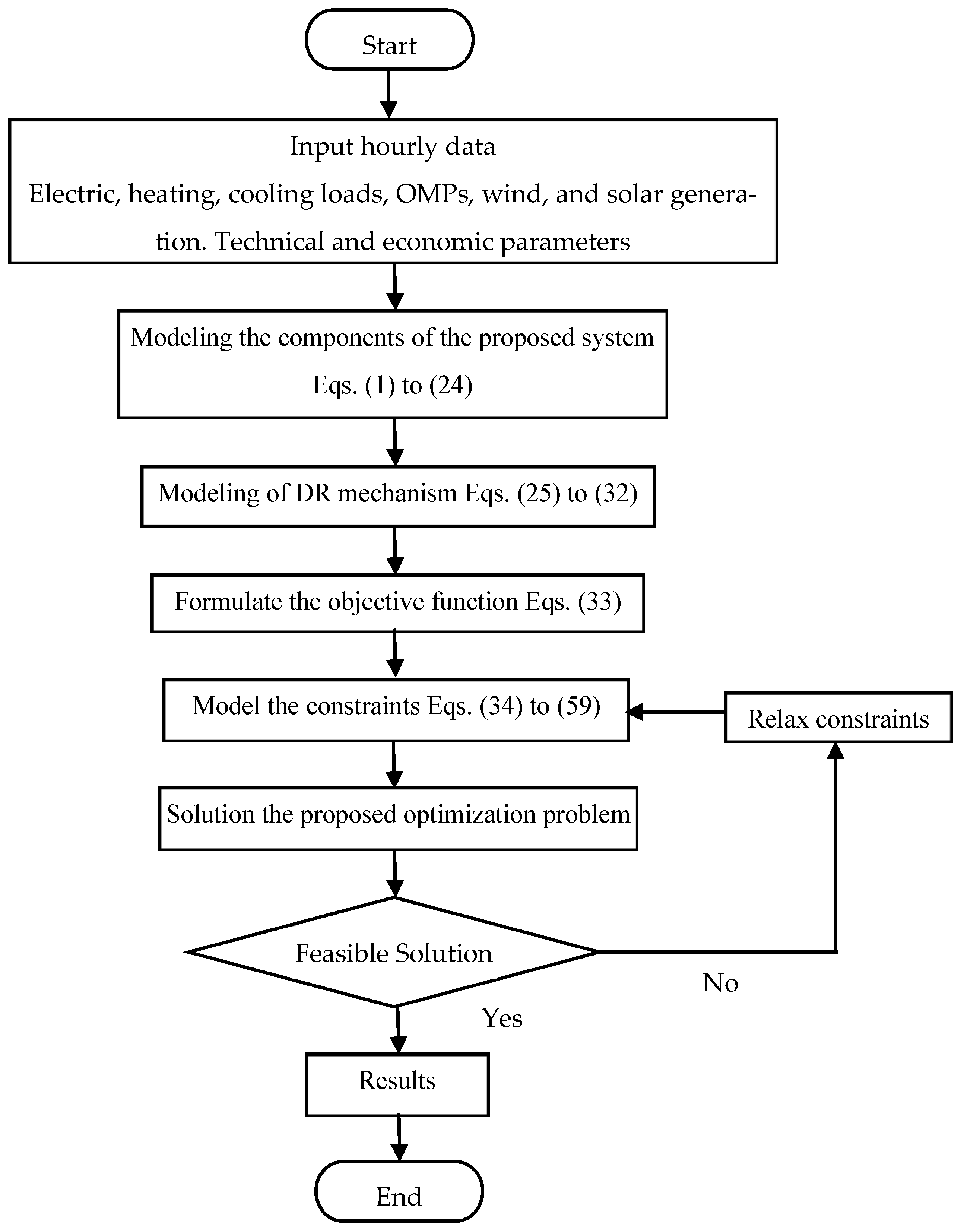
39]. The flowchart shown in
Figure 1 depicts the process that has been followed to formulate and solve the proposed optimization problem. Firstly, each component of the CCHP is formulated based on its economic operation function. Additionally, the constraints relevant to the operation are modelled and formulated as aforementioned in the previous section. Further, the combined objective function is formulated to minimize the operation and emission cost as in Equation (33). This objective function is modelled as UCIMIQP. Finally, the entire problem is solved, and the results are obtained.
There are many algorithms and methods in the open literature to solve the variety of optimization problems of the CCHP systems. The mature and famous methods are as follows: deterministic methods (liner programming (LP), non-linear programming (NL), mixed integer linear programming (MILP), mixed integer quadratic programming (MIQP), and dynamic programming (DP)), heuristic and metaheuristic methods (genetic algorithm (GA), particle swarm optimization (PSO), simulated annealing (SA), grey wolf optimizer (GWO), and multi-objective evolutionary algorithms (MOEAs)), artificial intelligence (AI) and machine learning (neural networks (NNs), fuzzy logic (FL), and reinforcement learning (RL)), and hybrid methods, which combine multiple techniques to combine their strength (MILP with metaheuristics, deterministic with stochastic methods, and metaheuristics with AI). The details of these methods, in aspects of formulation and suitability of each one to solve a specific optimization problem efficiently better than others with relevant algorithms, and comparisons between these methods are presented in the references [
40,
41,
42,
43,
44,
45,
46,
47,
48,
49]. Real-time and model predictive control energy management systems of the microgrids are addressed in [
39,
50].
Selecting the suitable solution method to formulate and solve the optimization problem depends on the types of the objective function, constraints and variables of the problem, the dimension of the problem, and where each optimization problem is different from others based on these criteria. In addition, the global optimal solution is a considerable factor in the formulation and solution of the optimization problem of CCHP systems, where the local optimum solution may be not an economic solution and affects the fidelity of the proposed approach [
48]. Similarly, the solution time is an important factor in the solution of the optimization problem, particularly in the case of online optimization. Clearly, choosing the solution methods is a vital decision in the formulation and solution of the optimization problem.
In this paper, the branch and bound algorithm is employed to solve the proposed UCIMIQP because when the solution is obtained that means the solution is the guaranteed global optimum and the solution time is not computationally intensive. In addition, the algorithm is integrated with an efficient solver [
49]. This simplifies the formulation and solution of the problem. Compared to the aforementioned methods, heuristic, metaheuristic, and hybrid methods are computationally intensive and stick to local optimum solutions, while model predictive control and real-time methods are suitable for the stochastic operation of the system.
Optimization is a key factor in formulating and solving the optimal operation of the modern smart grids that supply not only electric loads but also heating and cooling loads in the combined low-emission system. In the conventional system that supplies only electric load, it is possible to operate without optimization, where each generator provides energy according to its rating regardless of its operational cost and emission level of GHGs. This will be a costly option that leads to pollution. In addition, to consider the UC in the conventional system, optimization should be utilized.
In the proposed CCHP, it is impossible to operate the system without optimization. This is because of the interaction between the operation of the electric, heating, and cooling systems, where the energy is converted from one form to another to make the system operate efficiently. In addition, trading energy with the main grid depends on the pricing system, and it is difficult to determine the amount and the time of the exchange in energy with the utility grid. Further, consideration of the electric and heat storage systems, which operate either in charging, discharging, or idle modes, increases the complexity of the problem, and it is possible to determine the amount of energy that needs to be charged or discharged and to specify a specific time of these operations modes. Furthermore, the UC and DR strategies are impossible to address without optimization, and the optimization problem dispatches the energy resources according to their cost functions.
6. Proposed CCHP System
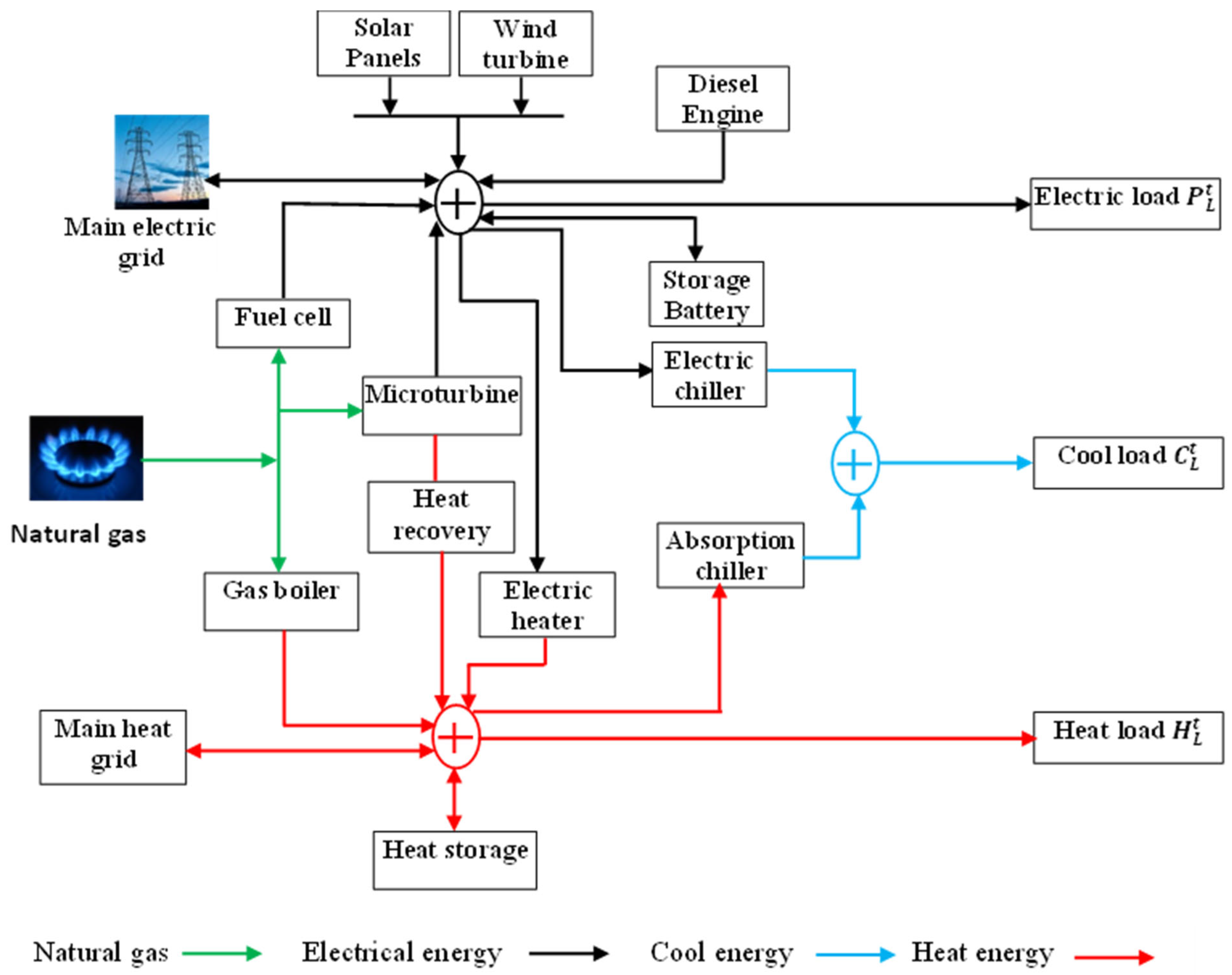
Figure 2 depicts the schematic arrangement of the proposed smart CCHP system. The CCHP supplies electricity, heating, and cooling loads. The CCHP system consists of an electric grid, a heating system, and a cooling system, where these systems interact to allow the flow of energy and supply their load in an economical and environmentally friendly framework. The electric system includes a variety of distributed generators (DGs) such as fuel cells (FCs), diesel generators (DEs), microturbine-based CHPs, wind turbines (WTs), and solar panels (PVs) and it has storage batteries (SBs). The heating system includes a gas boiler (GB), electric heater (EH), heat storage tank (HS), and heat recovery (HR) to recover waste heat from the CHP generator. The cooling system encompasses an electric chiller (EC) and an absorption chiller (AC). The CHP is fueled by natural gas to produce electric and heat energy simultaneously, whereas FC and GB consume natural gas (NG) to generate electric and heat energy. In addition, the EH transforms electric power to heat. Furthermore, the EC utilizes electricity to supply a cooling load, while the AC employs heat to generate cooling energy. The different loads are satisfied by the exchange of energy between these systems and the utility grids.
The hourly electrical and thermal energy demands, along with the corresponding energy exchange prices, are detailed in
Table 1. The generation profiles of photovoltaic (PV) and wind turbine (WT) systems are illustrated in
Figure 3. These data points are sourced from credible studies [
33,
51]. The rated delivering and absorbing power of the SB is 90 kWh, while the rated high and low levels of charge of the SB are 300 kWh and 90 kWh, respectively. The rated maximum and minimum stored energy of the HS are 300 kWh and 90 kWh, respectively. The rates of GB and the electric heater are 150 kWh and 500 kWh, respectively. The ramp rates of the CHP, FC, DE, GB, and AC are set at 100 kW, 30 kW, 70 kW, 120 kW, and 160 kW, respectively. The system combines multiple energy generation and storage technologies to balance supply and demand efficiently. The maximum output power in kW of CHP, FC, DG, GB, EH, and grid exchange capacities is 200, 60, 140, 150, 500, 200, 200, 100, and 200, respectively, while the minimum output power is 20, 5, 20, 5, 5, 10, 10, 5, and 5.
7. Results and Discussion
Two scenarios have been conducted for the CCHP system under study. The first scenario is conducted without applying demand control, while the second one is conducted with application of demand response to emphasise the impact of the shifting demand side response program on the optimal operation of the proposed CCHP system.
7.1. Scenario 1
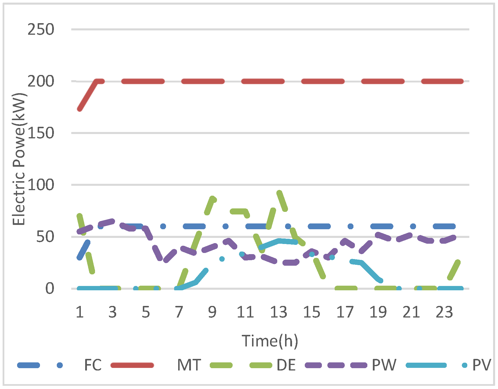
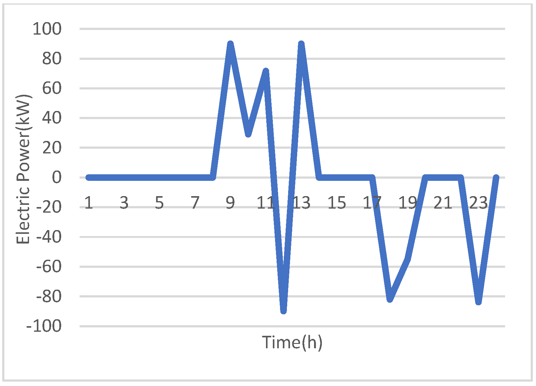
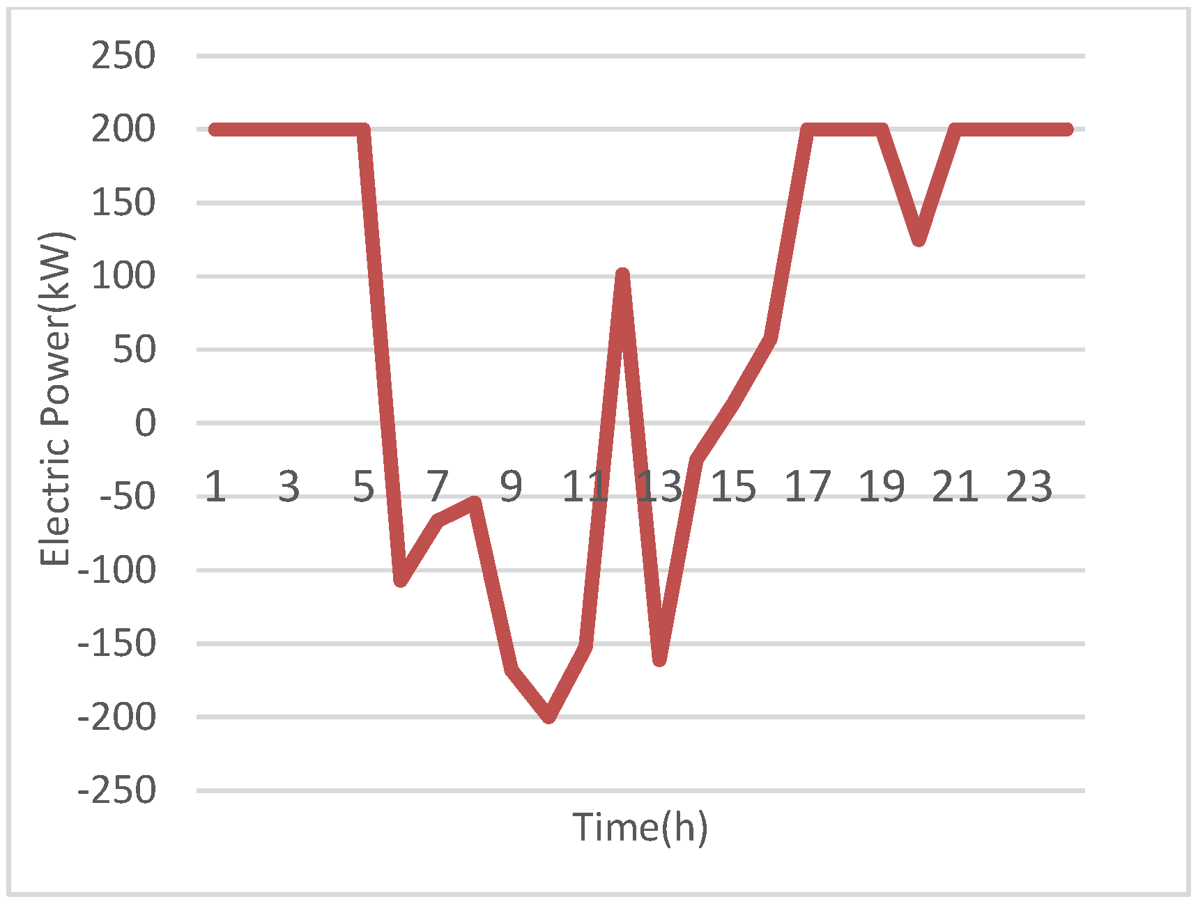
Figure 4,
Figure 5 and
Figure 6 depict the optimal planning of the electric generators and exchange in electric energy with the SB and the main system. It is observed from
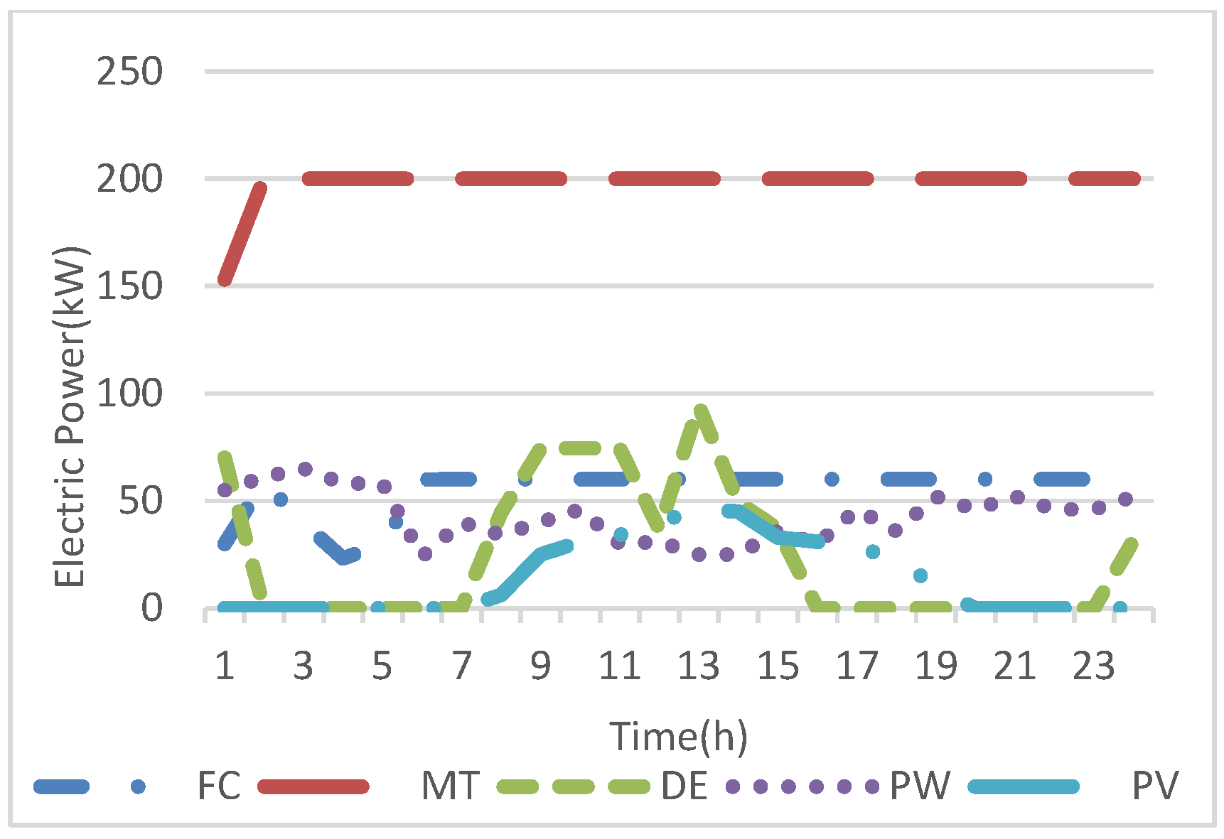
Figure 4 that the MT is operated during the whole scheduling time to supply both electric and heat loads. Additionally, the FC operates 24 h as well to supply the electric loads, where it is operated at hours 1 to 5 with less than maximum power because the EEOMP has low values at these hours and the CCHP system purchases the highest possible energy from the upstream system to supply the electric and heat loads through the EH and EC. Whereas, at these hours, the CCHP system exports the largest possible heat energy to the upstream system because the HEOMP has the highest values during the scheduling horizon, as shown in
Figure 7. The DE operated for much fewer hours than the MT and FC due to its high operating cost. Nevertheless, the DE is committed when the electric, heating, and cooling loads have high value because the electric power is required to supply the heating and cooling loads through the EH and EC. Despite the high operating cost of the DE, it is operated at hour 24 to meet the high electricity and heat demands. And thermal loads are supplied through the EH and EC because the SB is unable at this hour to respond to the constraint that the state of charge of the SB should be at maximum value at the end of the scheduling day. In addition, the solar energy equals zero as shown in
Figure 3 and
Figure 5. The SB is discharged when the EEOMP has peak values, where the SB supplied the highest possible energy at hour 13 when the price has the highest value and the electric load has a high value as well (as shown in
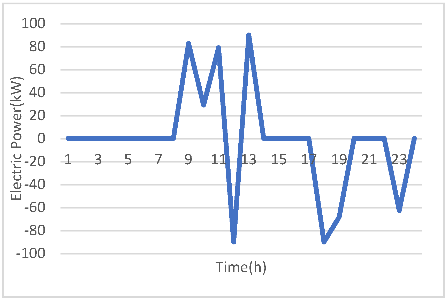
Figure 5). Additionally, the SB is charged the highest possible energy at hours 12 and 18, where at hour 12, the price has a lower value than hour 13 and renewable energies are abundant. Therefore, the SB is charged at 12 and discharged at hour 13 to increase the system revenue, while at hour 18 the SB is charged again because the EEOMP has quite a low value and to meet the limit to charge the SB until maximum. The CCHP system exports the highest electric energy to the main system at hours 9 and 10 because the EEOMP has the highest values during these hours and the electric load has low values with abundant wind and solar energies, as shown in
Figure 2 and
Figure 6. This is to minimize the expense and increase the revenue of the CCHP system.
Figure 7,
Figure 8 and
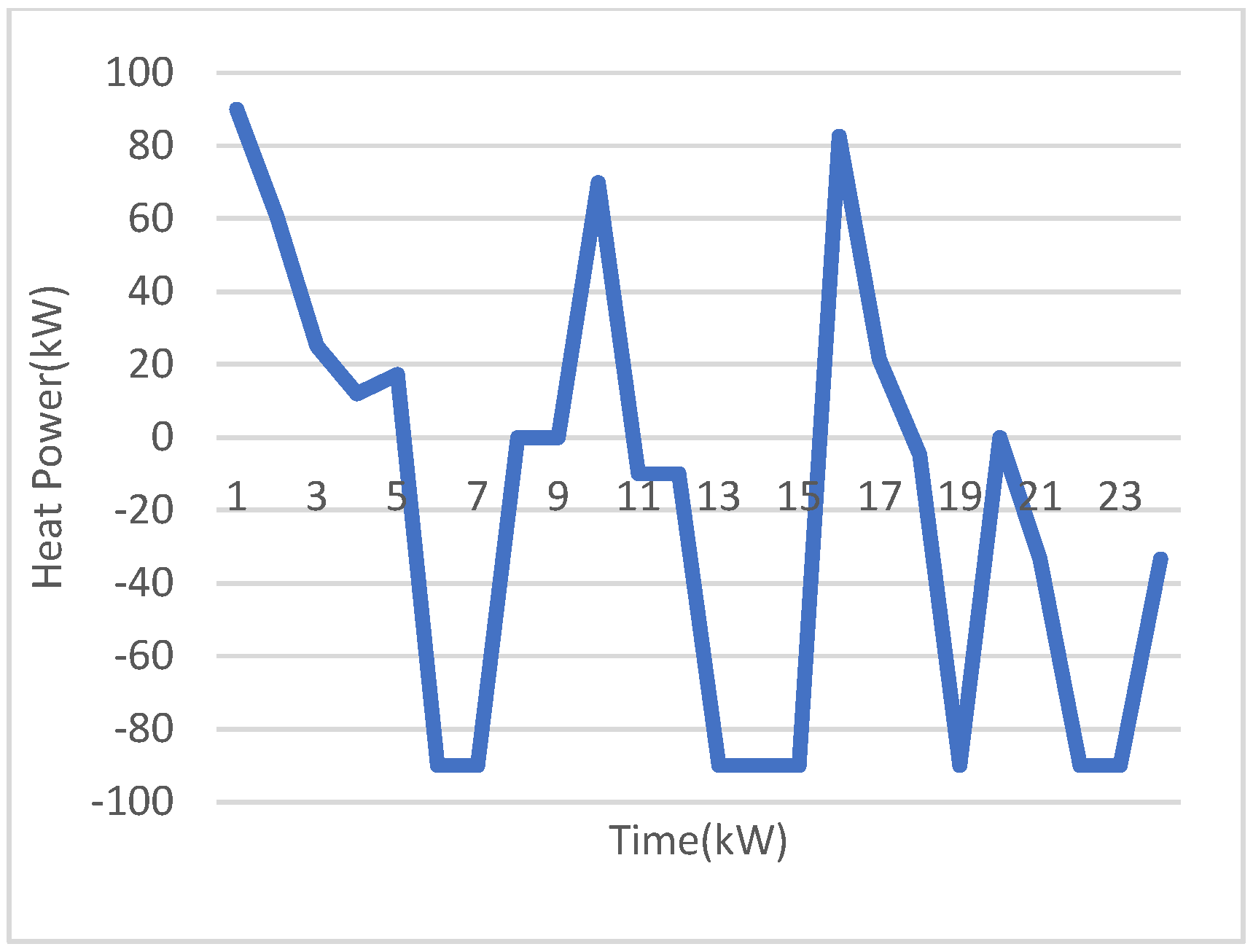
Figure 9 depict the hourly optimal planning of the thermal system. It is noticed from
Figure 6 that the MT provides heat during the entire day to supply other heat energy sources for the heat load. In addition, the GB boiler is operated during the whole time as well to provide the heat load during the day. The EH is committed to fewer hours compared to the GB. This is due to the dependence of the heat energy of the EH on the electric system, where the electric energy price at uncommitted hours of the EH has the highest values and the electric load is high. The HS supplies heat energy during hours 1 and 2 when the HEOMP has the highest values to minimize the total expense. The HS is charged when the price has the lowest value as depicted in
Figure 8.
Figure 9 demonstrates that the CCHP system provides the highest possible heat energy to the main system at hours 1 to 5, 16, and 17 to reduce the total cost and increase the revenue. This is because the HEOMP arrives at high values at these hours. Similarly, the CCHP system purchases high heat energy at hours 19, 20, 23, and 24 because the heat load has the highest values at these hours.
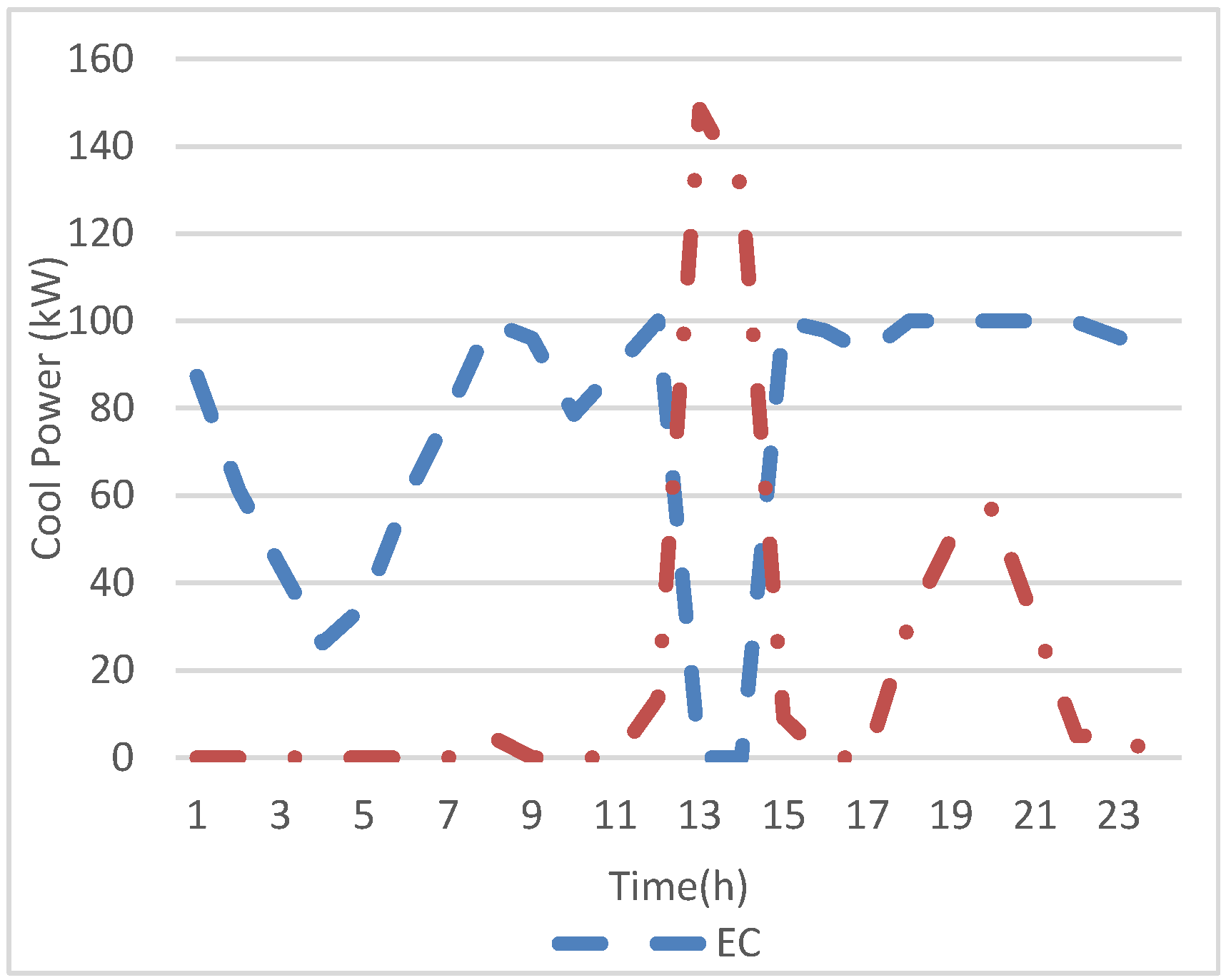
Figure 10 shows the output of cooling energy of the EC and AC. It can be seen that the AC is uncommitted at hours 1 to 11 because the AC needs heat energy to operate, where the heat load at these hours is quite high and the HEOMP shows peak values at these hours. Therefore, the EC supplies the load at these hours because the electric load has low values at these hours and renewable energy generation is abundant. However, the EC is uncommitted at hours 13 and 14. This is due to high electric load and high EEOMP at these hours. In the cooling system, it is obvious that the generators of cooling energy depend on the electric and heating systems.
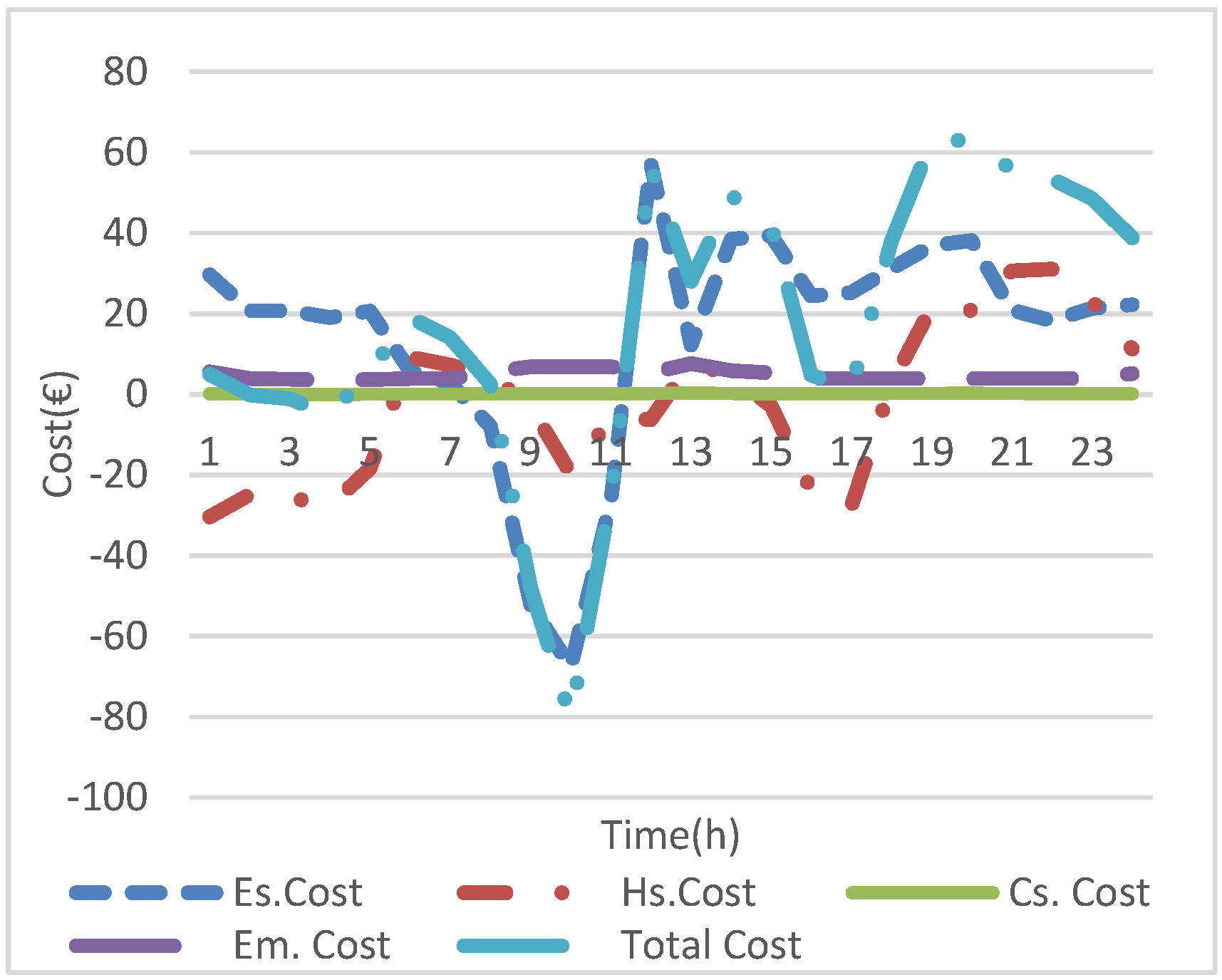
Figure 11 depicts the hourly costs of electric, heating, and cooling systems, in addition to emissions and the total cost. It is revealed that the electric cost has the highest cost among other costs because the electric system supplies electric load, heating, and cooling loads through interfacing generators, and emission cost belongs to the electric generators. Further, the peak values of the expense of the electric cost are at hours 18, 19, and 20 because the electric, thermal, and cooling loads reach the highest values, and the renewable energy is unabundant, while the electric system cost has negative values at hours 9, 10, and 11. These negative values mean revenue for the system from selling power to the utility grid. The peak expense of the heating system is at hours 21 and 22 because the heating load reaches peak values at these hours. It is also obvious that the expense of the heating system has negative values for more hours than the electric system. This is due to the selling of heat energy to the utility grid and the cooling system. The cost of the cooling system has positive values only during the scheduling day because the cooling system purchases power from the electric and heating systems to supply its load. The emission expense reaches the highest value at hour 13 because the MT, FC, and DE generate the highest energy at this hour. Furthermore, the total cost follows the pattern of the electric system cost because it has the highest cost and includes emission cost as well.
7.2. Scenario 2
In this scenario, managing both the generation and the demand side is conducted by considering the DR program, which is integrated with a problem as decision variables. In this scenario, the impact of the DR program on the optimal planning of electric, heating, and cooling systems is investigated. The DR of electric loads affects the optimal planning of the heating and cooling system because the electric system supplies the heating and cooling systems with electric energy to fuel some of the heating and cooling generators.
Figure 12 shows the impact of the DR on the electric load. This figure shows that the peak hour load is shaved and shifted to off-peak hours.
Figure 13,
Figure 14 and
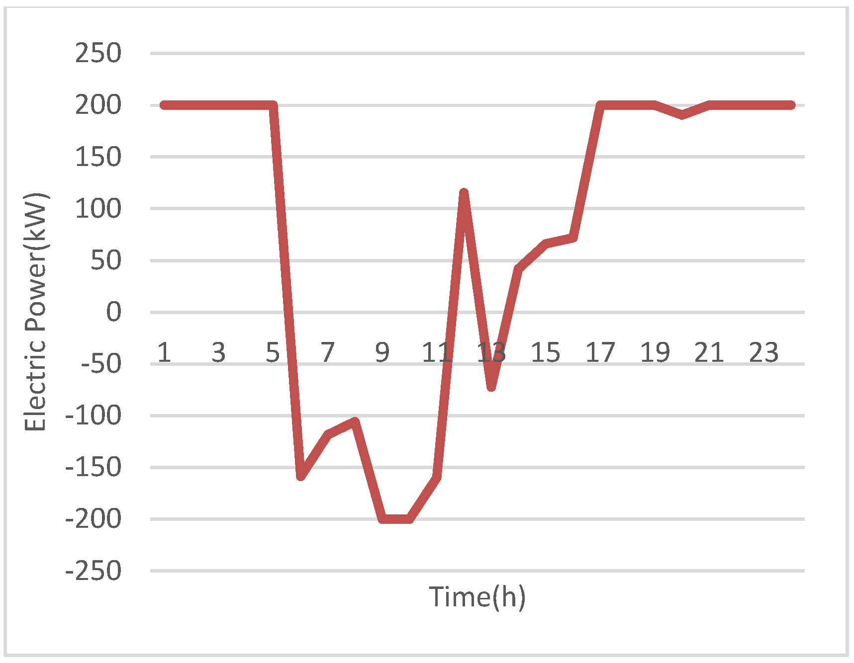
Figure 15 depict the optimal schedule of the electric energy generators, SB, and exchange of electric energy with the utility grid. It can be seen from
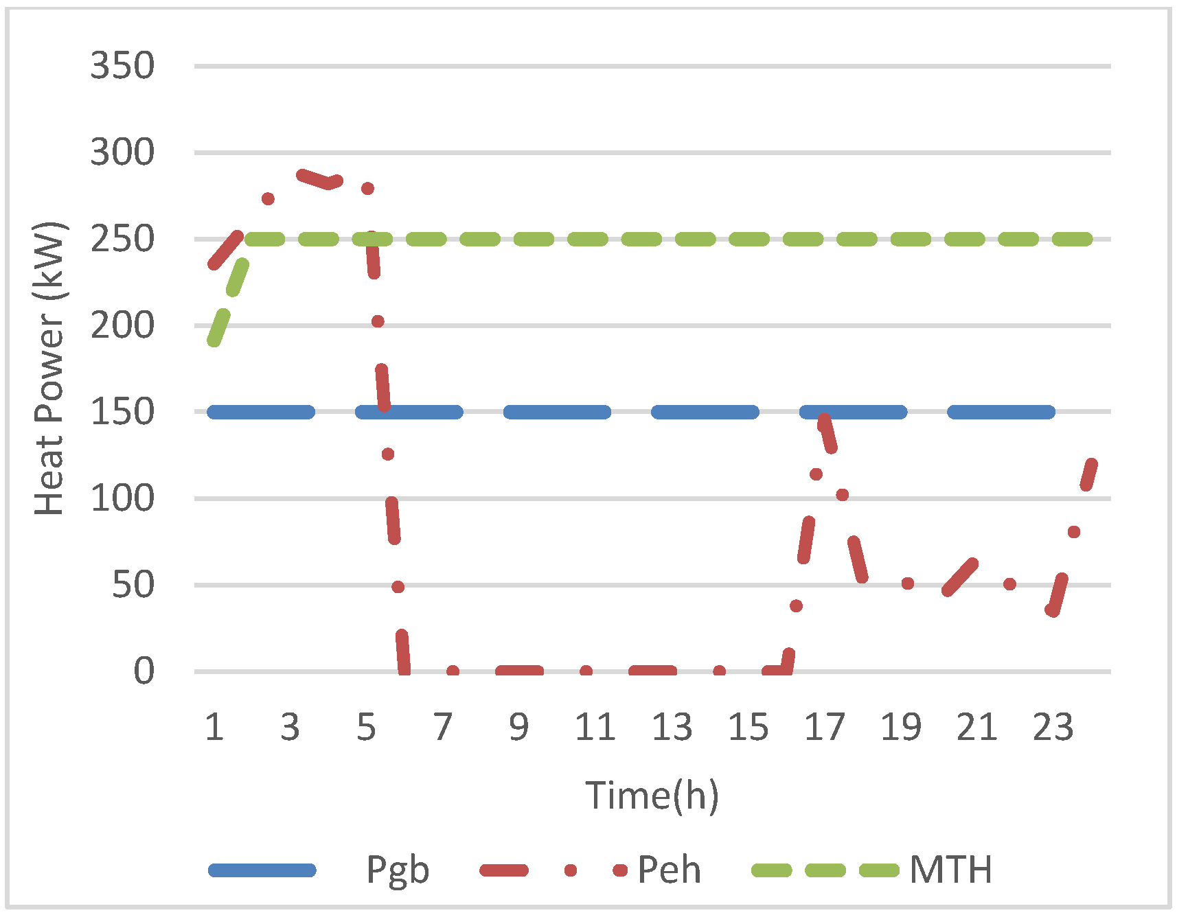
Figure 13 that the commitment of the MT, FC, and DE is the same as in scenario 1. However, the generation of the MT and the FC at hours 1 to 7 is higher in this scenario compared to scenario 1 because at these hours the shifted load is recovered; therefore, the generators increase their generation to meet the recovered load. In addition, the EH supplies less electric power at these hours and the HS compensates for this energy as shown in
Figure 16 and
Figure 17. It also reveals that the EH receives more electric energy at hours 19 to 24 because the electric load is cut and shifted to off-peak hours; therefore, the electric system supplies more energy to the heating system at these hours.
It can be observed from
Figure 15 compared to
Figure 6 that the system exports higher electric energy to the main system at hour 13 and sells energy at hour 14 in this scenario, while in scenario 1 it purchases energy from the main grid at this hour. This is because the electric load reaches peak values and the EEOMP has high values; therefore, the load is cut and shifted from these hours to low peak hours, and the CCHP system sells higher power to the main system to reduce the expense and increase the revenue. The SB has the same optimal operation as in scenario 1 with a small change in the charging and discharging energy. The optimal schedule of the cooling system is exactly the same as scenario 1 because this system depends on the electric and heat systems.
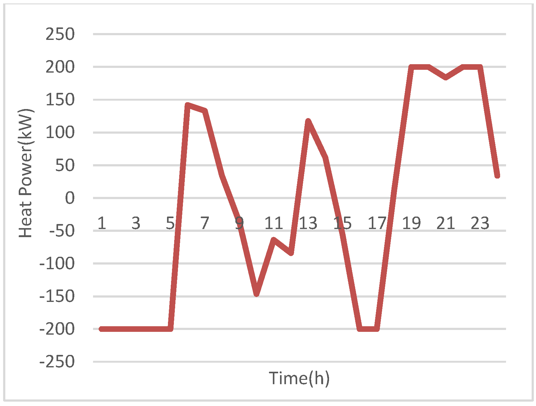
By comparing
Figure 8 and
Figure 17, it can be observed that the HS is discharged at hours 3 to 5 in this scenario, while it is uncommitted in scenario 1. This is because in this scenario the electric load is recovered; therefore, less electric energy is supplied to the heating system.
Figure 18 demonstrates that the CCHP system exports less heat energy to the main heat grid because the electric load is recovered at a high heat load.
The CCHP systems spend EUR 376.2 when considering the DR technique, whereas they spend EUR 430.1 without considering the DR program during the scheduling day. It is clear that applying the DR program reduces the total operating and environmental damage cost by 12.5% of the total cost. The DR reduces the peak loads, which improves the load factor and the security of the supply and spinning reserve.
8. Conclusions
This paper presents a combined objective to minimize the total expense of operation and emission levels of the CCHP system, where the emission is converted to monetary form and the problem can be solved directly in one step. The problem is formulated as UCIMIQP, where the energy exchanges between the electric, heating, and cooling systems and the energy is converted from one form to another through the systems’ energy generators. The cooling system is considered a side system and the energy interaction is overlooked, where this limitation will be considered clearly in future research. This interaction leads to a reduction in the total cost. The UC strategy is applied to the electric, heating, and cooling systems simultaneously, where the UC is improved to respond to the operation of the electric, heating, and cooling systems in one entire approach. The UC takes into consideration the interaction between systems. Additionally, the DR technique as peak clipping and shifting is considered and integrated with the optimization problem as a decision variable. The approach is applied to the CCHP system to verify the applicability and effectiveness of the proposed model.
The simulation results reveal that exchanging energy between different systems and converting it from one form to another reduces the total operation and emission costs. In addition, the operations of the SB and the HS are controlled to minimize the total cost for both scenarios. Furthermore. The DR program considerably reduces the total expense of operating and environmental damage to the system and reduces the peak load. Additionally, applying the DR program changes the electric and heat generator schedules due to the interaction of these systems.
Author Contributions
Methodology, G.A.B. and M.K.A.-S.; investigation G.A.B., M.K.A.-S. and G.A.A.-S.; writing—original draft preparation, G.A.B., M.K.A.-S. and G.A.A.-S.; writing—review and editing, G.A.B., M.K.A.-S. and W.A.K.A.-M.; supervision, W.A.K.A.-M. All authors have read and agreed to the published version of the manuscript.
Funding
This research received no external funding.
Institutional Review Board Statement
Not applicable.
Informed Consent Statement
Not applicable.
Data Availability Statement
The original contributions presented in the study are included in the article, further inquiries can be directed to the corresponding author.
Acknowledgments
The authors would like to thank the University of Technology, Iraq.
Conflicts of Interest
The authors declare no conflict of interest.
References
- Khader, M.A.; Ghavami, M.; Al-Zaili, J.; Sayma, A.I. Residential Micro-CHP system with integrated phase change material thermal energy storage. Energy 2024, 300, 131606. [Google Scholar] [CrossRef]
- Dobre, C.; Costin, M.; Constantin, M. A Review of Available Solutions for Implementation of Small–Medium Combined Heat and Power (CHP) Systems. Inventions 2024, 9, 82. [Google Scholar] [CrossRef]
- Smaisim, G.F.; Abed, A.M.; Hadrawi, S.K.; Majdi, H.S.; Shamel, A. Modelling and optimization of combined heat and power system in microgrid based on renewable energy. Clean Energy 2023, 7, 735–746. [Google Scholar] [CrossRef]
- Garcet, J.; De Meulenaere, R.; Blondeau, J. Enabling flexible CHP operation for grid support by exploiting the DHN thermal inertia. Appl. Energy 2022, 316, 119056. [Google Scholar] [CrossRef]
- Jin, T.; Chen, X.; Wen, J.; Wu, Q.; Bai, L.; Liu, Y.; Cao, Y. Improved Ramping and Reserve Modeling of Combined Heat and Power in Integrated Energy Systems for Better Renewable Integration. IEEE Trans. Sustain. Energy 2022, 13, 683–692. [Google Scholar] [CrossRef]
- Tiwari, V.; Dubey, H.M.; Pandit, M.; Salkuti, S.R. CHP-Based Economic Emission Dispatch of Microgrid Using Harris Hawks Optimization. Fluids 2022, 7, 248. [Google Scholar] [CrossRef]
- Mohammed, K.A.-S. Economic Operation Planning of Combined Heat and Power Smart Distribution System. J. Eng. Sci. Technol. 2021, 16, 25–43. [Google Scholar]
- Ahn, H.; Miller, W.; Sheaffer, P.; Tutterow, V.; Rapp, V. Opportunities for installed combined heat and power (CHP) to increase grid flexibility in the U.S. Energy Policy 2021, 157, 112485. [Google Scholar] [CrossRef]
- Jordehi, A.R. Economic dispatch in grid-connected and heat network-connected CHP microgrids with storage systems and responsive loads considering reliability and uncertainties. Sustain. Cities Soc. 2021, 73, 103101. [Google Scholar] [CrossRef]
- Salman, C.A.; Li, H.; Li, P.; Yan, J. Improve the flexibility provided by combined heat and power plants (CHPs)—A review of potential technologies. e-Prime Adv. Electr. Eng. Electron. Energy 2023, 1, 100023. [Google Scholar] [CrossRef]
- Kang, L.; Sun, D.; Zhao, W.; Wang, W.; Wu, X.; Zhang, X.; Yang, Y.; Wang, Y. Research on optimization method of CCHP system coupled with renewable energy. Sci. Technol. Energy Transit. 2024, 79, 70. [Google Scholar] [CrossRef]
- Yang, Y.; Zhou, Z.; Xiao, X.; Pang, Y.; Shi, L. Intelligent day-ahead optimization scheduling for multi-energy systems. Front. Energy Res. 2024, 11, 1349194. [Google Scholar] [CrossRef]
- Zeng, A.; Hao, S.; Xu, Q.; Liu, Y.; Huang, Y. A Day-Ahead Optimal Economic Dispatch Schedule for Building CCHP System Based on Centralized Energy Storage Infrastructure. Elektron. Elektrotechnika 2018, 24, 53–58. [Google Scholar] [CrossRef]
- Liu, Y.; Liu, T.; He, S. Coordination and Optimization of CCHP Microgrid Group Game Based on the Interaction of Electric and Thermal Energy Considering Conditional Value at Risk. IEEE Access 2021, 9, 88664–88673. [Google Scholar] [CrossRef]
- Luo, Z.; Gu, W.; Gao, S.; Wang, Z.; Tang, Y.; Company, J.E.P. Optimal Operation of a CCHP Microgrid Using Interval Mixed-Integer Linear Programming. J. Clean Energy Technol. 2017, 5, 174–182. [Google Scholar] [CrossRef]
- Wang, Q.; Liu, J.; Hu, Y.; Zhang, X. Optimal Operation Strategy of Multi-Energy Complementary Distributed CCHP System and its Application on Commercial Building. IEEE Access 2019, 7, 127839–127849. [Google Scholar] [CrossRef]
- Xie, H.; Liu, H.; Wan, C.; Goh, H.H.; Rahman, S. Optimal Scheduling of Integrated Energy Systems With Multiple CCHPs for High Efficiency and Low Emissions. IEEE Internet Things J. 2023, 10, 22623–22635. [Google Scholar] [CrossRef]
- Ghersi, D.E.; Amoura, M.; Loubar, K.; Desideri, U.; Tazerout, M. Multi-objective optimization of CCHP system with hybrid chiller under new electric load following operation strategy. Energy 2021, 219, 119574. [Google Scholar] [CrossRef]
- Cheng, J.; Huang, Y.; He, H.; Ibrahimi, A.M.; Senjyu, T. Optimal Operation of CCHP System Combined Electric Vehicles Considering Seasons. Energies 2023, 16, 4229. [Google Scholar] [CrossRef]
- Luo, Z.; Wu, Z.; Li, Z.; Cai, H.; Li, B.; Gu, W. A two-stage optimization and control for CCHP microgrid energy management. Appl. Therm. Eng. 2017, 125, 513–522. [Google Scholar] [CrossRef]
- Marino, C.; Marufuzzaman, M.; Hu, M.; Sarder, M.D. Developing a CCHP- microgrid operation decision model under uncertainty. Comput. Ind. Eng. 2018, 115, 354–367. [Google Scholar] [CrossRef]
- Luo, Z.; Wang, Z.; Gu, W.; Tang, Y.; Xu, C. A Two-Stage Energy Management Strategy for CCHP Microgrid considering house characteristics. In Proceedings of the 2015 IEEE Power & Energy Society General Meeting, Denver, CO, USA, 26–30 July 2015; pp. 1–5. [Google Scholar] [CrossRef]
- Gu, W.; Wang, Z.; Wu, Z.; Luo, Z.; Tang, Y.; Wang, J. An Online Optimal Dispatch Schedule for CCHP Microgrids Based on Model Predictive Control. IEEE Trans. Smart Grid 2017, 8, 2332–2342. [Google Scholar] [CrossRef]
- Ha, T.; Zhang, Y.; Thang, V.V.; Huang, J. Energy hub modeling to minimize residential energy costs considering solar energy and BESS. J. Mod. Power Syst. Clean Energy 2017, 5, 389–399. [Google Scholar] [CrossRef]
- Hu, J.; Liu, X.; Shahidehpour, M.; Xia, S. Optimal operation of energy hubs with large-scale distributed energy resources for distribution network congestion management. IEEE Trans. Sustain. Energy 2021, 12, 1755–1765. [Google Scholar] [CrossRef]
- Javadi, M.S.; Lotfi, M.; Nezhad, A.E.; Anvari-Moghaddam, A.; Guerrero, J.M.; Catalao, J.P.S. Optimal operation of energy hubs considering uncertainties and different time resolutions. IEEE Trans. Ind. Appl. 2020, 56, 5543–5552. [Google Scholar] [CrossRef]
- Al-Saadi, M.K. Coordination of Load and Generation Sides to Reduce Peak Load and Improve Arbitrage of Smart Distribution Grid. Int. J. Eng. 2023, 36, 226–235. [Google Scholar] [CrossRef]
- Jafari, E.; Soleymani, S.; Mozafari, B.; Amraee, T. Optimal operation of a micro-grid containing energy resources and demand response program. Int. J. Environ. Sci. Technol. 2018, 15, 2169–2182. [Google Scholar] [CrossRef]
- Wang, Y.; Huang, Y.; Wang, Y.; Li, F.; Zhang, Y.; Tian, C. Operation optimization in a smart micro-grid in the presence of distributed generation and demand response. Sustainability 2018, 10, 847. [Google Scholar] [CrossRef]
- Aghajani, G.; Shayanfar, H.; Shayeghi, H. Demand side management in a smart micro-grid in the presence of renewable generation and demand response. Energy 2017, 126, 622–637. [Google Scholar] [CrossRef]
- Wang, X.; Palazoglu, A.; El-Farra, N.H. Operational optimization and demand response of hybrid renewable energy systems. Appl. Energy 2015, 143, 324–335. [Google Scholar] [CrossRef]
- Kinhekar, N.; Padhy, N.P.; Li, F.; Gupta, H.O. Utility oriented demand side management using smart AC and Micro DC grid cooperative. IEEE Trans. Power Syst. 2015, 31, 1151–1160. [Google Scholar] [CrossRef]
- Li, Y.; Zou, Y.; Tan, Y.; Cao, Y.; Liu, X.; Tian, S.; Bu, F. Optimal stochastic operation of integrated low-carbon electric power, natural gas, and heat delivery system. IEEE Trans. Sustain. Energy 2018, 9, 273–283. [Google Scholar] [CrossRef]
- Mohammed, K.; Al-Saadi, P.L. Profit-Based Online Optimal Planning of Low Emission Multi-Energy Distribution System. J. Eng. Sci. Technol. 2022, 17, 1287–1305. [Google Scholar]
- Bayendang, N.P.; Kahn, M.T.; Balyan, V. Combined cold, heat and power (CCHP) systems and fuel cells for CCHP applications: A topological review. Clean Energy 2023, 7, 436–491. [Google Scholar] [CrossRef]
- Farzin, H.; Fotuhi-Firuzabad, M.; Moeini-Aghtaie, M. Stochastic Energy Management of Microgrids during Unscheduled Islanding Period. IEEE Trans. Ind. Inform. 2017, 13, 1079–1087. [Google Scholar] [CrossRef]
- Roy, P.K.; Ghoshal, S.P.; Thakur, S.S. Combined economic and emission dispatch problems using biogeography-based optimization. Electr. Eng. 2010, 92, 173–184. [Google Scholar] [CrossRef]
- Hadi, H. Solving the combined economic load and emission dispatch problems using new heuristic algorithm. Electr. Power Energy Syst. 2013, 46, 10–16. [Google Scholar]
- Parisio, A.; Rikos, E.; Glielmo, L. A Model Predictive control approach to microgrid operation optimization. IEEE Trans. Control. Syst. Technol. 2014, 22, 1813–1827. [Google Scholar] [CrossRef]
- Deb, K.; Pratap, A.; Agarwal, S.; Meyarivan, T. fast and elitist multiobjective genetic algorithm: NSGA-II. IEEE Trans. Evol. Comput. 2002, 6, 182–197. [Google Scholar] [CrossRef]
- Deb, K.; Jain, H. An evolutionary many-objective optimization algorithm using reference-point-based nondominated sorting approach, part I: Solving problems with box constraints. IEEE Trans. Evol. Comput. 2013, 18, 577–601. [Google Scholar] [CrossRef]
- Gao, K.; Wang, T.; Han, C.; Xie, J.; Ma, Y.; Peng, R. A Review of Optimization of Microgrid Operation. Energies 2021, 14, 2842. [Google Scholar] [CrossRef]
- Bagherian, M.; Mehranzamir, K.; Pour, A.B.; Rezania, S.; Taghavi, E.; Nabipour-Afrouzi, H.; Dalvi-Esfahani, M.; Alizadeh, S.M. Classification and Analysis of Optimization Techniques for Integrated Energy Systems Utilizing Renewable Energy Sources: A Review for CHP and CCHP Systems. Processes 2021, 9, 339. [Google Scholar] [CrossRef]
- Zhu, S.; Xu, L.; Goodman, E.D.; Lu, Z. A new many-objective evolutionary algorithm based on generalized Pareto dominance. IEEE Trans. Cybern. 2022, 52, 7776–7790. [Google Scholar] [CrossRef]
- Salehi, N.; Martinez-Garcia, H.; Velasco-Quesada, G.; Guerrero, J.M. A Comprehensive Review of Control Strategies and Optimization Methods for Individual and Community Microgrids. IEEE Access 2022, 10, 15935–15955. [Google Scholar] [CrossRef]
- Alsagri, A.S.; Alrobaian, A.A. Optimization of Combined Heat and Power Systems by Meta-Heuristic Algorithms: An Overview. Energies 2022, 15, 5977. [Google Scholar] [CrossRef]
- Abdi, H. A Survey of Combined Heat and Power-Based Unit Commitment Problem: Optimization Algorithms, Case Studies, Challenges, and Future Directions. Mathematics 2023, 11, 4170. [Google Scholar] [CrossRef]
- Akter, A.; Zafir, E.I.; Dana, N.H.; Joysoyal, R.; Sarker, S.K.; Li, L.; Muyeen, S.M.; Das, S.K.; Kamwa, I. A review on microgrid optimization with meta-heuristic techniques: Scopes, trends and recommendation. Energy Strategy Rev. 2024, 51, 101298. [Google Scholar] [CrossRef]
- Amorim, A.P.A.; Pontes, K.V.; Dorneanu, B.; Arellano-Garcia, H. Optimizing microgrid design and operation: A decision-making framework for residential distributed energy systems in Brazil. Chem. Eng. Res. Des. 2024, 214, 251–268. [Google Scholar] [CrossRef]
- Ghadimi, P.; Kara, S.; Kornfeld, B. Real-Time Operation Management of CHP System in Manufacturing Industry. Mod. Appl. Sci. 2014, 9. [Google Scholar] [CrossRef][Green Version]
- Xie, D.; Lu, Y.; Sun, J.; Gu, C.; Yu, J. Optimal operation of network-connected combined heat and powers for customer profit maximization. Energies 2016, 9, 442. [Google Scholar] [CrossRef]
| Disclaimer/Publisher’s Note: The statements, opinions and data contained in all publications are solely those of the individual author(s) and contributor(s) and not of MDPI and/or the editor(s). MDPI and/or the editor(s) disclaim responsibility for any injury to people or property resulting from any ideas, methods, instructions or products referred to in the content. |
© 2025 by the authors. Licensee MDPI, Basel, Switzerland. This article is an open access article distributed under the terms and conditions of the Creative Commons Attribution (CC BY) license (https://creativecommons.org/licenses/by/4.0/).
