Article

Optimization Control of Sub-Synchronous Oscillations in Doubly Fed Generators with Wind Turbines Using the Genetic Algorithm

School of Mechanical and Electrical Engineering, China University of Mining & Technology-Beijing, Beijing 100083, China
*
Author to whom correspondence should be addressed.
Appl. Sci. 2025, 15(3), 1353; https://doi.org/10.3390/app15031353
Submission received: 11 December 2024 / Revised: 11 January 2025 / Accepted: 26 January 2025 / Published: 28 January 2025

Abstract

:
The sub-synchronous oscillation accident of large-scale doubly fed wind turbines connected to a grid through series compensation has caused a serious impact on the power system. By optimizing the parameters of the doubly fed wind turbines control system, the system impedance can be effectively improved to solve the problem of sub-synchronous oscillation. However, owing to the complexity of a grid-connected system of doubly fed generators connected to wind turbines and the influence of the time-varying oscillation characteristics of the system, it is often difficult to achieve a successful suppression. To solve this problem, this paper proposes an optimized additional damping method for the rotor- and grid-side controllers, which can achieve efficient suppression of the sub-synchronous oscillation. The parameters of the proposed additional damping method are optimized for all variable operation conditions using a genetic algorithm under the established frequency–domain impedance model. The detailed time–domain simulation model was constructed with the RTLAB platform to verify the proposed method. The experimental results show that the optimized control strategy can effectively and quickly suppress the sub-synchronous oscillation under different operating conditions, and the amplitude suppression rate reached 85.99%, which effectively improved the grid-connected stability of the wind turbines.

1. Introduction

By the end of 2022, the cumulative installed photovoltaic capacity and wind power capacity in the world were approximately 1.2 TW. The Global Wind Energy Report 2024 highlights increasing momentum of the growth of wind energy worldwide: The total installations of 117 GW in 2023 represent a 50% year-on-year increase from 2022. Furthermore, 2023 was a year of continued global growth—54 countries representing all continents built new wind power [1]. GWEC has revised its 2024–2030 growth forecast (1210 GW) upwards by 10% in response to the establishment of national industrial policies in major economies [2].
In its latest annual market report on renewable energy in 2023, the International Energy Agency predicted that the global renewable energy capacity will grow significantly over the next six years, eventually reaching an ambitious target of 7300 GW [3]. This growing trend reflects not only the growing global focus on clean energy but also the enormous potential for technological advancements and cost reductions [4]. This transformation will have a profound impact on the global energy structure, marking an important step in the path of human society toward combating climate change and promoting green development.
Sub-synchronous oscillation (SSO) accidents caused by large-scale doubly fed wind farms after they are integrated into the grid system through series compensation have become a major influencing factor that threatens the safe and stable operation of wind turbines and power grids. In the early 1970s, the first SSO accident occurred at the Mohave power plant in the United States, which caused a serious accident in which the shafting of the generator set was broken [5]. In October 2009, owing to a change in the system structure of a doubly fed wind farm in southern Texas, USA, the series compensation degree increased sharply from 50% to 75%, triggering an SSO phenomenon of approximately 20 Hz. The voltage and current waveform distortion was severe, resulting in damage to the crowbar circuit and a large number of wind turbines going off the grid [6]. From the end of 2012 to the end of 2013, 58 oscillation events occurred on wind farms in Guyuan, Hebei Province, China. In December 2012, a doubly fed wind farm in Guyuan County, Zhangjiakou City, Hebei Province, China was connected to a power system with a fixed series compensation, causing a major SSO accident. At the beginning of the accident, the output current of the affected wind turbines quickly became unstable; its maximum amplitude increased abnormally to more than 30%, and the oscillation frequency of the current was stable at approximately 7.9 Hz. Because of this anomaly, the protection mechanism of the wind turbine was triggered, resulting in many wind turbines tripping and leaving the grid, which in turn caused the current in the grid to exhibit an attenuation trend. After taking emergency measures such as shutting down some wind turbines, the entire system gradually returned to a stable state [7]. In 2016, Tongyu County, Baicheng City, Jilin Province repeatedly encountered SSO phenomena with frequencies of approximately 5 Hz, but these phenomena disappeared when the related series compensation system was turned off [8].
After much research, scholars have divided SSO into the following three types according to its causes: sub-synchronous resonance (SSR), sub-synchronous torsional interaction (SSTI), and sub-synchronous control interaction (SSCI). Ref. [9] proposed that with an increase in the series compensation, the minimum value of the equivalent resistance further decreases, the natural resonant frequency of the system increases, and the danger area of the DFIG effect moves to the high-wind-speed region and becomes more intense. Ref. [10] illustrated that when the equivalent electrical negative damping of the system is greater than the sum of the equivalent positive damping of the stator and transmission systems, the output power diverges and oscillates. Ref. [11] pointed out that the SSO caused by the device is mainly studied in the field of thermal power units, and there are few studies on wind power, because this problem has not been encountered in actual engineering. Ref. [12] summarized the mechanism of SSCI and the influence of the controller and system parameters on SSCI and summarized the research methods and main inhibitory measures of SSCI. Ref. [13] revealed that the interaction between wind turbines and the series compensation system is the key factor that triggers SSO, and further studies have found that the negative damping characteristics of DFIG at sub-synchronous frequencies are the main reason for SSCI. The analysis results show that the oscillation frequency of the wind turbines changes continuously with time, the grid operation mode, and the number of generators. References [10,11] investigated the influencing factors of SSO. In this paper, a model was built in Simulink and experiments were conducted to verify the impact of external operating conditions on SSO. On the basis of the former theory, this paper further validated the influence of the proportional coefficients of the outer loops of the rotor-side converter (RSC) and the grid-side converter (GSC) on SSO, discovering that a larger proportional coefficient in the outer loops intensifies SSO. Ref. [14] proposed a control method for attaching a virtual impedance to the rotor-side converter of a doubly fed wind turbine, where the real part of the virtual impedance improves the damping characteristics of the system and thus suppresses the SSO. Ref. [15] proposed a sub-synchronous virtual resistance strategy, which plays the role of increasing the sub-synchronous oscillation damping and suppressing the oscillations by introducing a virtual resistance in the sub-synchronous frequency band in the control of the wind turbine motor side, which can be physically interpreted as a series of virtual resistors in the rotor circuit of the motor. Ref. [16] designed an additional power-controlled sub-synchronous damping controller and provided a strategy for tuning the parameters of this controller to optimize its performance. Ref. [17] proposed a damping controller design method that is more adaptive than the traditional damping controller, which is mainly based on a self-immobilizing controller that can effectively inhibit the SSO phenomenon in a doubly fed wind power system under different operating conditions and improve the stability of the system. Ref. [18] proposed an SSCI damping control strategy based on the multiple-input multiple-output state-space approach and pointed out that the configuration of the SSDC in the rotor-side converter has a better damping performance with a more significant effect than the inclusion of the GSC. The control methods proposed in References [12,13,16,17,18] incorporate adding damping controllers only in the grid-side or rotor-side control system on one side. This paper presents a control strategy that introduces a sub-synchronous damping controller (SDC) simultaneously on both the grid and rotor sides, with experimental verification showing superior suppression effectiveness. References [14,15] presented parameter optimization strategies. This paper utilizes the genetic algorithm to optimize the parameters of the SDC, achieving parameter optimization across all operating conditions. Furthermore, the primary objective of the method proposed in this paper is to enhance the SSO damping of the DFIG itself, particularly the oscillations between the DFIG and series compensation. When other types of wind turbines are connected in the vicinity, the improved damping of the DFIG itself can still effectively suppress the oscillations.
There are primarily three existing methods to suppress SSO: The first is to disconnect series compensation, but this can reduce the transmission capacity of wind power. The second method involves utilizing an SVG (Static Var Generator) or STATCOM (Static Synchronous Compensator) to add supplementary damping control for oscillation suppression, although this approach is constrained by the capacity of the SVG or STATCOM. The third method involves modifying the control of wind turbines, mainly by altering the strategies for stator and rotor control. This paper focuses on the third method and, building upon previous research, is the first to address the optimization of controllers on both sides. The research results demonstrate that the proposed method achieves better damping effects.
At present, research on the mechanism of SSO has been relatively sufficient, but there is no effective, efficient, and convenient method for the optimization and transformation of doubly fed wind turbines and the inhibition and solution of SSO problems. Based on the research of scholars, this study analyzes the factors influencing SSO through frequency domain impedance modeling and time domain simulation analysis, proposes an optimal suppression strategy based on the sub-synchronous damping controller (SDC), and optimizes the parameters through a large number of experiments to achieve the best suppression effect to improve the stability and reliability of the overall operation of the system.
The main contributions of this study can be summarized as follows:
  • For the first time, the cooperative damping method for the grid-side and rotor-side control systems of the DFIG is proposed to solve the SSO problem of doubly fed wind power via a series-capacitor grid-connected system.
  • The parameters, including the gain and phase shift of the proposed SSO damping method, are optimized using the genetic algorithm to achieve the best performance for all variable operation conditions.
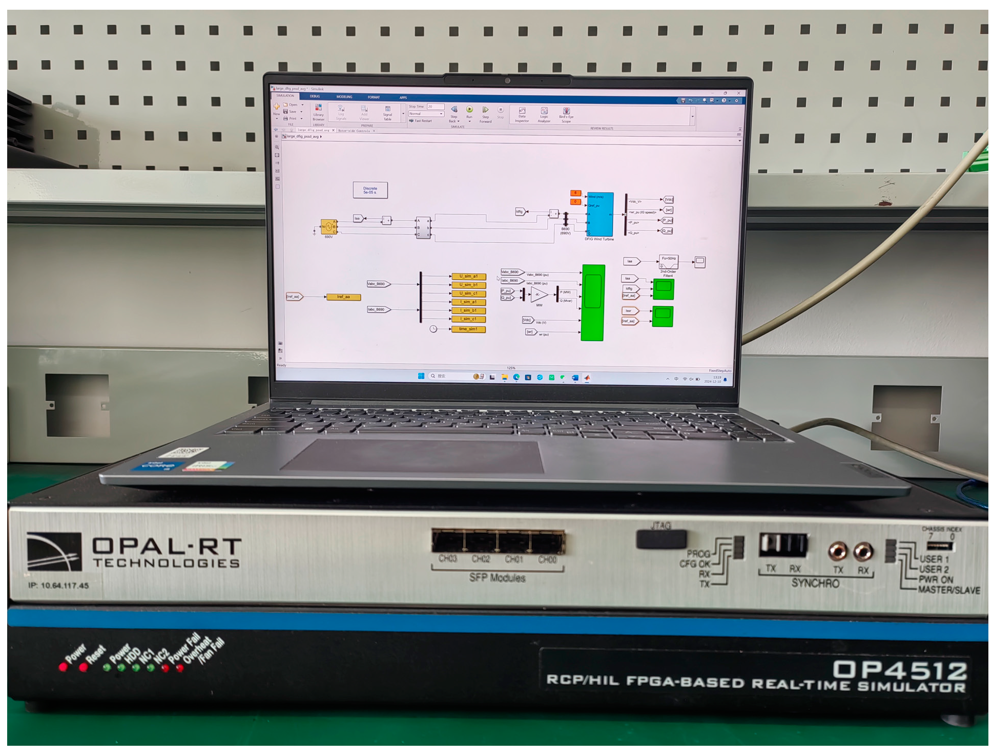
  • The proposed optimized SSO damping method is verified with the established model under the RTLAB platform.
The structure of the paper is as follows: The second part establishes the mathematical model and frequency domain impedance model of the doubly fed wind turbine grid-connected system via series compensation, and deduces the impedance function of the system, to reasonably speculate the influence of the parameters on the SSO. The third part designs the SDC, which is added into the control system of the doubly fed wind turbine, and the fourth part of the article utilizes the genetic algorithm to obtain the optimal parameter settings. The fifth part builds a time-domain simulation model in the RTLAB platform, verifies the suppression effect of the SDC, and obtains the control table of parameter settings and SSO amplitude suppression rate through experiments to realize the optimal suppression effect. Finally, the summary and outlook are obtained.

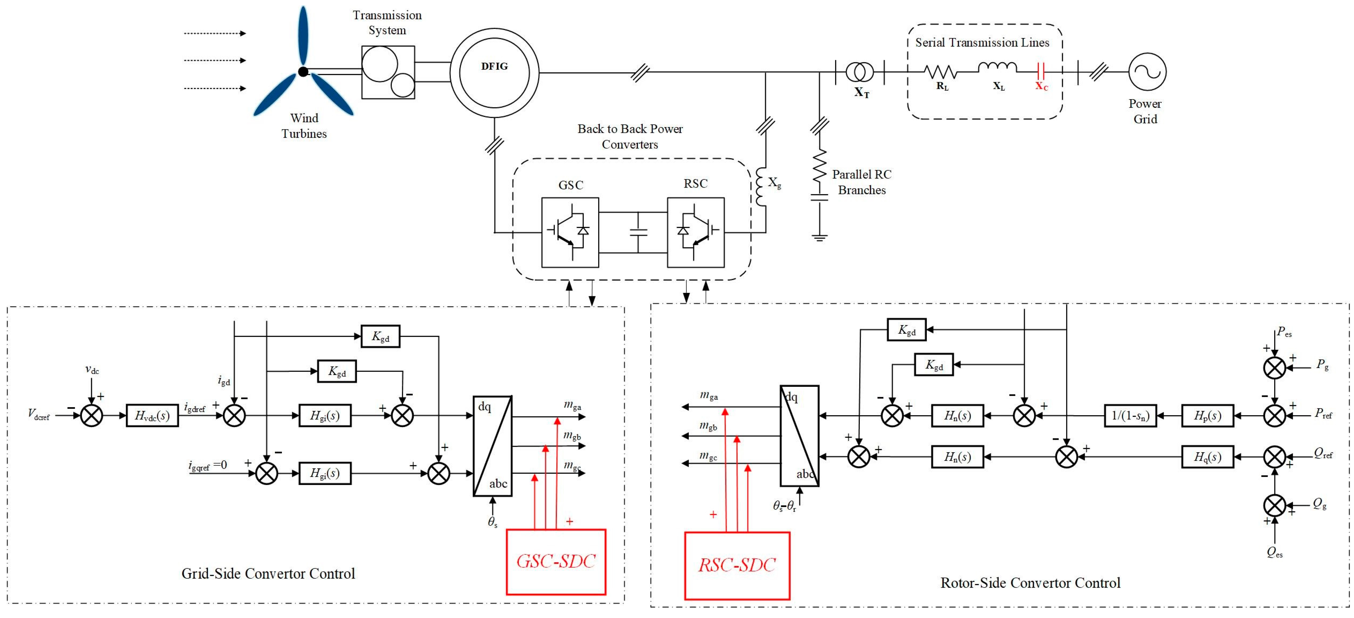
2. Modeling of the Grid-Connected Systems of Doubly Fed Wind Turbines Through Series Compensation

2.1. Mathematical Model of Doubly Fed Asynchronous Wind Turbines

Doubly fed induction generators (DFIGs) are not only the core components of variable-speed constant-frequency wind turbines, but are also a key component in the process of promoting the localization of wind turbines. The design and application of DFIGs are of great significance for improving the efficiency and reliability of wind power systems.
The “doubly fed” in DFIG’s name comes from its unique structure: the stator is directly connected to the grid, the rotor is connected to the grid through a set of back-to-back converters, and both the stator and rotor are involved in feeding power to the grid. The doubly fed wind turbine mainly includes a wind turbine, transmission system, doubly fed induction motor, back-to-back power converter, and control system, and its complete topology is shown in Figure 1. These components work together to ensure that the wind turbines can efficiently and consistently convert wind energy into electricity. The back-to-back power converters of the DFIG are composed of rotor-side converters (RSCs) and grid-side converters (GSCs) to achieve stable energy flow. XT is the reactance of the step-up transformer, and RL and XL are the equivalent resistance and reactance of the transmission line, respectively. XC is the reactance of the series compensation capacitor of the transmission line.
This paper proposes an optimized additional damping method for both the rotor- and grid-side controllers, which can achieve efficient suppression of sub-synchronous oscillations.

2.2. Grid-Side Converter Control Model

The typical control structure of the GSC is shown in the “Grid-Side Converter Control” part in Figure 1, which consists of two control parts: the outer loop of the DC voltage and the inner loop of the AC current. The balance of the instantaneous active power between the RSC and GSC determines the DC voltage, which is achieved by controlling the active component of the GSC AC current, that is, the d-axis component. Power factor control can be achieved by adjusting the reactive component of the GSC AC current, that is, the q-axis component [19].
The voltage difference between the three modulation voltages of the GSC and that of the three-phase AC port acts on the filter inductor to generate a three-phase AC current. The GSC AC loop time–domain model can be expressed as
v g i = K m v d c m g l = v l + s L f i g i
Table 1 lists the meaning of each physical quantity.

2.3. Rotor-Side Converter Control Model

The typical control structure of the RSC is shown in the “Rotor-Side Converter Control” part of Figure 1. Links related to the slip rate are added to the rotor current control. The DFIG unit’s total output power is regulated through the active and reactive powers of the outer control loop. In the inner AC control loop, the active power can be controlled by adjusting the d-axis component of the rotor winding’s alternating current, while the reactive power can be managed by modifying the q-axis component of the rotor winding’s alternating current [20].
The RSC AC port is connected to the rotor winding, its modulation voltage acts directly on the rotor winding, and the time domain model of the RSC AC loop is
v r l = K e K m v d c m r l
Table 1 lists the meaning of each physical quantity.

2.4. Frequency Domain Impedance Model

According to Figure 2, the impedance function of the system is constructed as follows:
Z = Z G S C Z R S C Z G S C + Z R S C + Z l + Z s + Z r
where Z is the total impedance of the system, Zl is the line impedance, Zs is the grid-side impedance, Zr is the rotor-side impedance, and ZGSC and ZRSC are the impedances of GSC and RSC in the control system, respectively. Each component is given by Equation (4):
Z l = R + s L 1 s C Z s = R s + s L l s Z r = R r s s j ω m + s L l r Z G S C = s s j ω m K p g + K i g s j ω Z R S C = s s j ω m K p r + K i r s j ω
where R, Rs, and Rl are the line, stator-side, and rotor-side resistances, respectively. L, Lls, Llr, and LM are the line inductance, grid-side inductance, rotor-side inductance, and grid and rotor mutual inductance, respectively; Kpg and Kig are the proportional and integral coefficients, respectively, in the GSC. Kpr and Kir are the proportional and integral coefficients of RSC, respectively. ω is the nominal angular velocity, taken as 377 rad/s; ωm is the angular velocity of the rotor; C is the series compensation capacitance; j is the imaginary number unit; and the resonant frequency can be obtained from s = jω0. The electrical power from the rotor side is converted to the grid side.
From Equations (3) and (4), it can be seen that the changes in the proportional coefficients of series capacitors C, GSC, and RSC, Kpg and Kpr, directly affect the size of the system impedance, while the number of fans affects the system torque, and the wind speed affects the rotor speed and indirectly changes the size of the system impedance. When the real part of the impedance is negative, the system presents a negative damping state, and there is a risk of SSO.

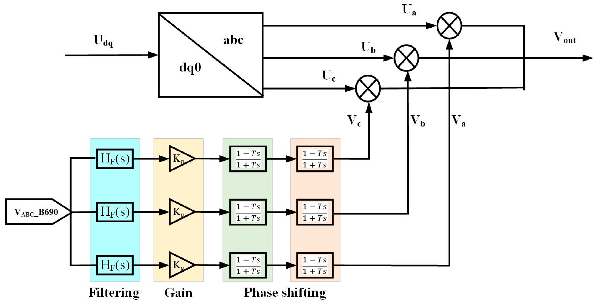
3. Additional Damping Controller Design

A traditional sub-synchronous damping controller (SDC) is generally a single-input, single-output system that includes gain, phase shifting, and clipping. The controller often uses the speed deviation signal Δω, active output Pmeas of the fan, and voltage as feedback signals [21].
In this study, an additional damping controller installed in the DFIG control system GSC and RSC is used, and the electrical characteristics of the access point can be equivalent to a controllable impedance. The bus voltage uabc of the doubly fed wind turbine is selected as the SDC feedback signal, which not only circumvents the problem of communication delays, but also behaves as an open circuit in the industrial frequency range and does not contain components complementary to the sub-synchronous mode in frequency.

3.1. Filter

The filter is used to extract the sub-synchronous signal based on the oscillating component of the feedback signal. As the core element in this process, it allows specific sub-synchronous frequency components of the signal to pass through while greatly attenuating other non-essential frequency components [22]. Through this process, the filtering link can ensure that the control system accurately identifies and processes the SSO, provides accurate and reliable signal input for the subsequent gain and phase compensation links, optimizes the interaction between the DFIG and the power grid, and improves the stability and performance of the system. In this study, the filtering link in the SDC includes two parts: a band-stop filter and a band-pass filter. The combined transfer function HF(s) is
H F ( s ) = H P ( s ) H S ( s )   H P ( s ) = s ω p 1 + 2 ζ p S ω p + s ω p 2   H S ( s ) = 1 + s ω S 2 1 + 2 ζ s S ω S + s ω S 2
where HS(s) is the transfer function of the band-stop filter and HP(s) is the transfer function of the band-pass filter.

3.2. Gain

The effectiveness of the additional damping control on the SSO does not depend solely on the choice of the feedback signal of the access point and the design of the filter, but also on the design of a well-designed gain link. By appropriately setting the gain coefficient, the control system can promptly and precisely output the corresponding voltage signal upon detecting the SSO, thereby effectively curbing the oscillation’s progression and enhancing the overall stability and reliability of the power system. Within a certain parameter range, increasing the gain K leads to a more effective suppression of the SSO. However, the limiting link needs to be considered, so it should not be set too large.

3.3. Phase Shifting

The PID phase compensation controller has the advantages of a simple structure, easy implementation of the algorithm, and strong robustness. In this study, a simple leading-lag control structure is used to generate a reference signal for the voltage loop, which makes it easy to adjust the gain and phase compensation parameters. The phase compensation formula is as follows:
1 T s 1 + T s
where T is the time constant of the phase compensation link.

3.4. Add the Impedance Transfer Function of SDC

SDC is added to the rotor-side and grid-side control systems, as shown in Figure 3.
Let the impedance transfer function after adding SDC be G(s), then,
    G ( s ) = V o u t U a b c
Taking phase A as an example, then,
G a ( s ) = V a o u t U a = U a + V a U a = 1 + V a U a   = 1 + V a B 690 U a [ H F ( s ) + K P + ( 1 T s 1 + T s ) 2 ]
where Vout is the output voltage after adding the SDC, and Uabc is the output voltage of the control system without the SDC. Vaout is the output voltage of phase A after adding the SDC, Ua is the phase A voltage at the output terminal of the control system without SDC, Va is the equivalent injection voltage of the SDC, V(a-B690) is the voltage of phase A of the generator, the transfer function of the filter link HF(s) is given by Equation(5), and KP is the gain.

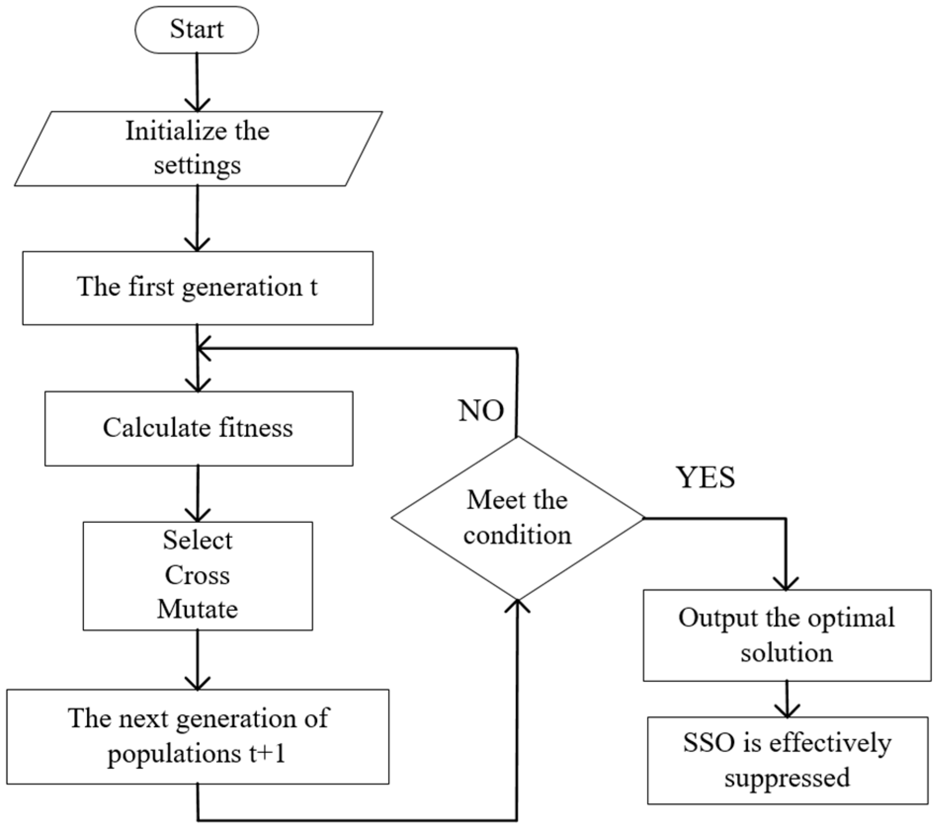
4. Parameter Optimization

The genetic algorithm (GA) is an approach that probabilistically seeks the optimal solution by mimicking the natural evolutionary process [23]. By utilizing mathematical techniques and computer simulations, it transforms the problem-solving process into one that resembles the biological evolution processes of selection, crossover, and mutation of chromosome genes. After multiple iterations and updates, the optimal solution to the problem is attained.
GA avoids the issue of traditional optimization algorithms easily becoming stuck in local optimal solutions by conducting a global population search. Additionally, GA exhibits strong adaptability and is suitable for complex optimization problems, making it well suited for parameter optimization in the control system of SDCs for doubly fed wind turbines. Thirdly, GA possesses robustness and is insensitive to the selection of the initial population, thus having low requirements for the manually set initial parameter values.
The parameter optimization method based on GA takes the fitness function as the evaluation criterion, uses MATLAB programming to realize the iterative calculation of the parameters of the SDC, and efficiently and quickly calculates the optimal parameters that should be set under different operating conditions to obtain the optimal suppression effect of the SSO.
Figure 4 shows the flow chart of the GA algorithm implementation. The algorithm implementation steps are as follows:
  • Initialize the population: select the dataset within the controllable range of the target parameters, and select the phase shift angle, gain, and serial compensation degree as the “genes” that can be operated. The initial parameters are set as follows: the crossing probability Pc is 0.5, the mutation probability Pm is 0.001, and the maximum number of iterations T is five.
  • Calculate the fitness values for different parameter combinations.
  • The cross-matching order is randomly generated, the cross-matching sequence is determined according to the crossover probability Pc, and the cross-operation is carried out one by one to generate a new group.
  • Individuals are randomly selected to determine whether the gene fragment is mutated according to the mutation probability Pm, and the mutation operation of the single gene fragment is performed to generate a new population.
  • Determine whether the suppression requirements are met; otherwise, proceed to Step 2 until the maximum number of iterations is reached, and the optimal solution is retained.
The optimization objective of this study is to calculate the optimal setting values of the gain K and phase-shift time constant T in the SDC for any operating condition using the GA algorithm to maximize the SSO amplitude rejection rate.
The index of the amplitude suppression rate is defined to describe the suppression effect of the SSO phenomenon under different SDC parameters. The relevant amplitude suppression rate is expressed as follows:
β = H a H b H a
where Ha and Hb represent the amplitude of the oscillation of the output waveform of the a-phase current Iaa before and after the addition of the SDC, respectively.
A mathematical model for parameter optimization is developed as shown in Equation (10):
m a x C ( β , K , T )   0 β 1   10 K g 64   30 K r 120   0.2 T g 0.99   0.2 T r 0.99

5. Simulation and Verification of SDC Inhibition Effect

5.1. Simulation and Verification of the Suppression Effect of SDCs Added to the Control System

The SDC are installed in the abc axis control structure at the output of the GSC and RSC and are enabled simultaneously.
In order to verify that the proposed optimization method can effectively suppress SSOs under all operating conditions, the time domain simulation was carried out with parameters such as the gain and phase-shift time constant in SDC as variables. Table 2 lists the parameters of the DFIG. The rated power and voltage of the stator were selected as the reference values. Iaa is the phase A current of the bus on the grid side The following operating conditions are taken as an example for simulation experiments. The wind speed was set to 6 m/s, the capacity of each DFIG was 1.5 MW, and the number of wind turbines was 100, and they were connected to the infinite power grid through the series compensation capacitor of 445F.
As shown in Figure 5, the proposed method was tested with the RTLAB platform. In Simulink, a model for the grid-connected system of a DFIG with series compensation was built. The process involved several steps: firstly, dividing the system into subsystems; secondly, adding the OpComm module; thirdly, maximizing parallel execution and configuring priority/state variables; fourthly, setting real-time parameters; and finally, running the model offline.
The SDC gains Kg and Kr installed in both the GSC and RSC, as well as the phase shift time constants Tg and Tr, were calculated from the GA. The current waveform without SDC under the same operating conditions was compared, and the amplitude suppression rate β was calculated according to Equation (9); results are shown in Table 3. Figure 6 and Figure 7 show the comparison of the current Iaa output waveform of phase A before and after adding the SDC; the red line in the figure is the Iaa output waveform before adding the SDC, and the blue line is the Iaa output waveform after the SDC is added.
After many experiments and analyses of the experimental results, the following conclusions were obtained:
  • Comparing Figure 6 and Figure 7, the optimization effect of adding SDC on both the grid side and rotor side is obviously better than adding SDC to the single-side controller only.
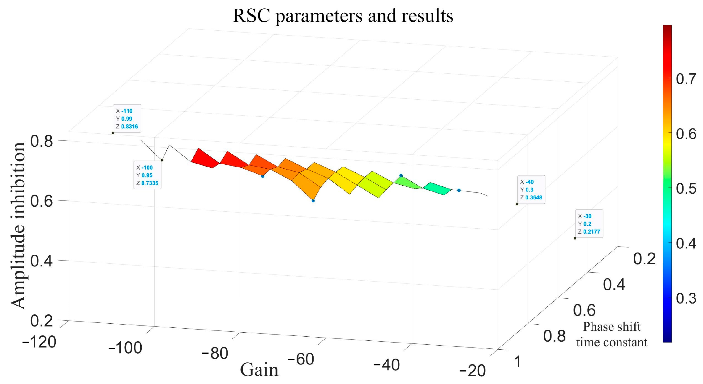
  • To achieve optimization under this working condition, the value range of the SDC gain Kg in the GSC is [−10, −64], the value range of the SDC gain Kr in the RSC is [−30, −120], and the value range of the phase-shift time constant T in the two control systems is [0.2, 0.99].
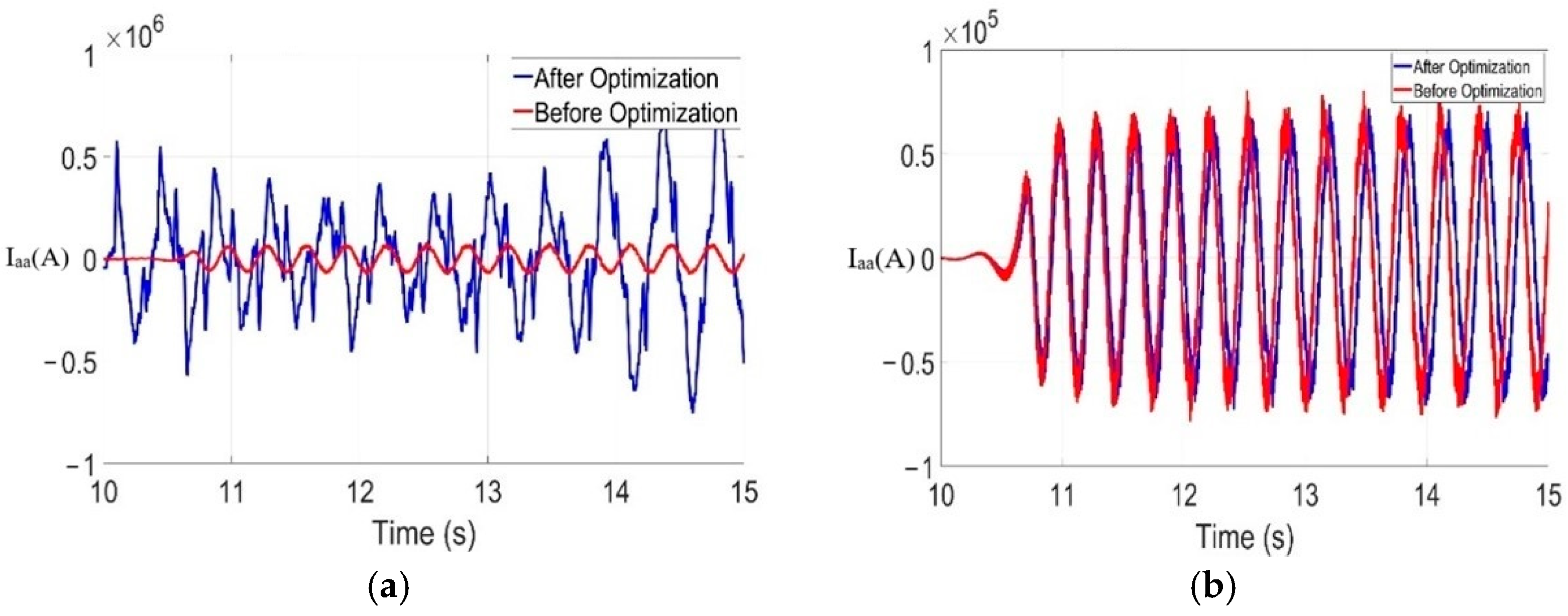
  • The gain K is related to the phase-shift time constant T, and the parameters should be synchronously increased or decreased. When the absolute value of K is extremely large and that of T is extremely small, the system becomes unstable, as shown in Figure 8a. When the absolute value of K is too small and that of T is too large, the inhibition effect is extremely insignificant, as shown in Figure 8b.
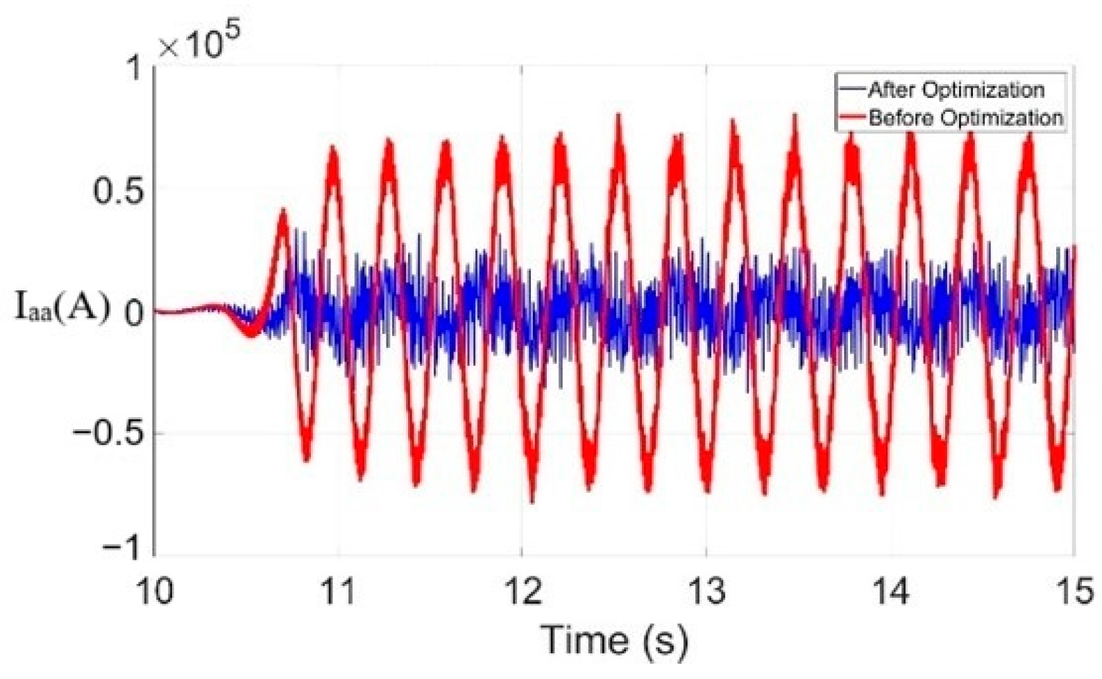
  • When the absolute values of K and T were increased, the inhibition effect was better. The combined inhibition effect was the best at 85.99% when Kg = −64, Tg = 0.95, Kr = −100, and Tr = 0.95, as shown in Figure 7.

5.2. Simulation and Verification of the Suppression Effect of SDC Added into the Control System Alone

In this study, SDC is added into the GSC and RSC control systems, the suppression effect is explored through simulation experiments, and a comparison table between the parameters and the SSO amplitude suppression rate is obtained. The three-dimensional diagram is drawn with code in MATLAB, as shown in Figure 9 and Figure 10, so that the relationship between the parameter setting and the suppression effect can be intuitively seen.
Comparing the inhibition effect with that of the combined addition of SDC, as shown in Table 4, it can be concluded that the joint inhibition effect when SDC is added to both the GSC and RSC systems is better than that of SDC alone in the control system under the same conditions.

6. Conclusions

To solve the SSO problem, this paper proposes an optimized additional damping method for the rotor- and grid-side control system of the DFIG, which can suppress the SSO successfully under variable operating conditions. First, the impedance model of the DFIG is established. Subsequently, a joint optimization strategy with SDC on both the grid and the rotor sides is proposed. Finally, the model is verified. The verification results show the following:
  • An innovative optimization method based on coordinated control of the rotor and grid sides was proposed. Compared with the method of adding an SDC on only one side of the rotor or grid control system, the combined optimization effect was better, with an amplitude suppression rate reaching 85.99%, which can more effectively solve the SSO problem existing in the doubly fed wind power grid-connected system via series compensation.
  • The genetic algorithm was used to optimize the design of the parameters of the SDC. Through the optimization algorithm, optimized suppression under all operating conditions can be achieved with different series compensation degrees, wind speeds, and numbers of wind turbines.
  • The experimental module was established on the RTLAB platform to simulate the experimental effects under different operating conditions and conduct the simulation research. The experimental results are consistent with theoretical derivations, and the experimental conclusions provide a reference value for the setting of various parameter thresholds in engineering practice.
In summary, the SSO suppression method for doubly fed wind turbines based on the GA proposed in this paper has a certain practical application value in addressing the challenges of power system stability and security, and also features both economy and convenience. It provides a guarantee for the safe and stable operation and efficient power transmission of wind farms and offers new ideas for the integration of artificial intelligence into new power systems.

7. Outlook

Based on the research in this paper, the following recommendations are proposed: It is recommended to incorporate SDCs on both the grid and rotor sides of doubly fed wind turbines connected to the grid via series compensation in order to reduce system damping, decrease the occurrence of SSO, and effectively lower the oscillation amplitude of SSO if it does occur. Additionally, the GA should be applied to optimize the parameters of the SDC, ensuring its effectiveness under all operating conditions.
For future work, we have the following plans:
  • To explore the impact of adding the point location of the SDC in the control system on the SSO suppression effect.
  • To investigate how to improve the fitness of the GA algorithm for the SDC model, thereby further enhancing the SSO suppression effect.

Author Contributions

Conceptualization, H.H. and Y.X.; methodology, X.Z.; validation, J.Y. and S.M.; formal analysis, L.G.; investigation, Q.X.; data curation, Y.X.; writing—original draft preparation, Y.X.; visualization, X.Z.; supervision, X.Z. All authors have read and agreed to the published version of the manuscript.

Funding

This research was supported by the Beijing Natural Science Foundation (3232051), Beijing Natural Science Foundation (L244005), the National Natural Science Foundation of China (52107135), and the Fundamental Research Funds for the Central Universities (2024ZKPYJD07).

Institutional Review Board Statement

Not applicable.

Informed Consent Statement

Not applicable.

Data Availability Statement

In this article, only the working conditions with obvious phenomena are fully recorded. For the full-condition optimization process, only the results were retained, so no dataset was created. In future studies, we will take care to preserve all the raw data for each stage in preparation for the creation of a complete data set.

Conflicts of Interest

The authors declare no conflict of interest.

References

  1. Global Wind Energy Report 2024. Available online: https://gwec.net/global-wind-report-2024/ (accessed on 10 December 2024).
  2. IRENA. Renewable Energy Statistics 2023; International Renewable Energy Agency: Abu Dhabi, United Arab Emirates, 2023. [Google Scholar]
  3. Liu, Y.; Wang, Z.; Shen, H.; Wei, Q.; Li, Q.; Zhang, X. The research of the superconducting magnetic energy storage model based on the real time digital system. In Proceedings of the 12th International Conference on Renewable Power Generation (RPG 2023), Shanghai, China, 14–15 October 2023; pp. 753–760. [Google Scholar] [CrossRef]
  4. Yang, W.; Liao, K.; Xiao, X.; Luo, C. Impact of Shunt reactor to DFIG Connected to Series-Compensated Power System on Sub-synchronous Oscillation Characteristics. MATEC Web Conf. 2018, 173, 02030. [Google Scholar]
  5. Ren, H.; Hou, B.; Zhou, G.; Shen, L.; Wei, C.; Li, Q. Variable Pitch Active Disturbance Rejection Control of Wind Turbines Based on BP Neural Network PID. IEEE Access 2020, 8, 71782–71797. [Google Scholar] [CrossRef]
  6. Dong, L.; Kong, J.; Feng, J.; Zhang, Y. Sub-synchronous Resonance Mitigation for Series Compensation Transmission System of DFIG Based on PR Control. In Proceedings of the 2019 IEEE 10th International Symposium on Power Electronics for Distributed Generation Systems (PEDG), Xi’an, China, 3–6 June 2019; pp. 734–738. [Google Scholar] [CrossRef]
  7. Chen, X.; Wang, Y.; Gong, C.; Sun, J. Overview of Stability Analysis of Grid-Connected Inverters Using Impedance Analysis Method. Proc. Chin. Soc. Electr. Eng. 2018, 38, 2082–2094. [Google Scholar]
  8. Sun, J. Impedance-based stability criterion for grid-connected inverters. IEEE Trans. Power Electron. 2011, 26, 3075–3078. [Google Scholar] [CrossRef]
  9. Zhen, Z.; Du, W.; Wang, H. Equivalence Proof of the Complex Torque Coefficient Method and Open-Loop Mode Stability Criterion in Strong Modal Coupling Phenomenon. Proc. Chin. Soc. Electr. Eng. 2019, 39, 2272–2279+10. [Google Scholar]
  10. Wang, Y.; Yu, H.; Liu, Z.; Ma, Y.; Zhao, G.; Deng, Z. Broadband Sub-synchronous Signal Extraction and Analysis of the Key Parameters. In Proceedings of the 2019 4th IEEE Workshop on the Electronic Grid (eGRID), Xiamen, China, 11–14 November 2019; pp. 1–6. [Google Scholar]
  11. Wen, B.; Boroyevich, D.; Burgos, R.; Mattavelli, P.; Shen, Z. Analysis of D-Q small-signal impedance of grid-tied inverters. IEEE Trans. Power Electron. 2016, 31, 675–687. [Google Scholar] [CrossRef]
  12. Xie, X.; Zhang, X.; Liu, H.; Liu, H.; Li, Y.; Zhang, C. Characteristic analysis of sub-synchronous resonance in practical wind farms connected to series-compensated transmissions. IEEE Trans. Energy Convers. 2017, 32, 1117–1126. [Google Scholar] [CrossRef]
  13. Ma, N.; Du, W.; Liu, P. Risk Assessment of Sub/Super-Synchronous Oscillation for Wind Power Based on Hardware-in-the-Loop Testing. Proc. Chin. Soc. Electr. Eng. 2022, 42, 5497–5506. [Google Scholar] [CrossRef]
  14. Vieto, I.; Sun, J. Sequence impedance modeling and analysis of type-III wind turbines. IEEE Trans. Energy Convers. 2018, 33, 537–545. [Google Scholar] [CrossRef]
  15. Tian, Y.; Liu, Y.; Xiao, Z.; Wang, Z.; Geng, Y.; Zhao, D. Research on Construction Scheme of New Generation Centralized Control Station Intelligent Monitoring System. In Proceedings of the 2023 3rd International Conference on Energy Engineering and Power Systems (EEPS), Dali, China, 28–30 July 2023; pp. 1004–1009. [Google Scholar] [CrossRef]
  16. Wang, Y.; Du, W.; Chen, C.; Wang, H. Study on Sub-synchronous Oscillation in Power Systems Caused by Wind Farms Connected to the Grid Based on Improved Complex Torque Coefficient Method. J. Electr. Eng. 2020, 35, 3258–3269. [Google Scholar]
  17. Miao, Z. Impedance-model-based SSR analysis for type 3 wind generator and series-compensated network. IEEE Trans. Energy Convers. 2012, 27, 984–991. [Google Scholar] [CrossRef]
  18. Yin, M.X.; Liu, H.; Li, Y.H.; Song, W. Research on the Impact on Sub-synchronous Resonance Risk from DFIG Number and Series-compensated Degree. J. Phys. Conf. Ser. 2018, 1087, 042075. [Google Scholar] [CrossRef]
  19. Chi, Y.; Liu, Y.; Wang, W.; Dai, H. Voltage Stability Analysis of Wind Farm Integration into Transmission Network. In Proceedings of the 2006 International Conference on Power System Technology, Chongqing, China, 22–26 October 2006; pp. 1–7. [Google Scholar] [CrossRef]
  20. Ghennam, T.; Berkouk, E.M.; Francois, B. DC-link voltage balancing algorithm using a space-vector hysteresis current control for three-level VSI applied for wind conversion system. In Proceedings of the 2007 European Conference on Power Electronics and Applications, Aalborg, Denmark, 2–5 September 2007; pp. 1–10. [Google Scholar]
  21. Liu, H.; Xie, X.; He, G. Impedance Modelling in Synchronous Reference Frame and Stability Discrimination Method for Grid-Connected New Energy Generation Systems. Proc. CSEE 2017, 37, 4002–4007. [Google Scholar]
  22. Li, Y.; Zhao, S.; Ma, Y. Impedance Modelling and Characteristic Analysis of Three-Phase LCL Grid-Connected Inverter. Electr. Power Autom. Equip. 2019, 39, 107–113. [Google Scholar]
  23. Xu, Y.; Zhao, S. Mitigation of Sub-synchronous Resonance in Series-Compensated DFIG Wind Farm Using Active Disturbance Rejection Control. IEEE Access 2019, 7, 68812–68822. [Google Scholar] [CrossRef]
Figure 1. The topology of the doubly fed wind turbine is connected to the grid through series compensation with the SDC connected to both the rotor side and grid side.
Applsci 15 01353 g001
Figure 2. System impedance modeling.
Applsci 15 01353 g002
Figure 3. Impedance schematic with SDC added.
Applsci 15 01353 g003
Figure 4. Algorithm implementation step diagram.
Applsci 15 01353 g004
Figure 5. Testing with RTLAB platform.
Applsci 15 01353 g005
Figure 6. Comparison of Iaa output waveforms of the SDC added only in the GSC.
Applsci 15 01353 g006
Figure 7. Comparison of Iaa output waveforms with the joint addition of the SDC in the GSC and RSC.
Applsci 15 01353 g007
Figure 8. Invalid verification.
Applsci 15 01353 g008
Figure 9. GSC parameter settings and results.
Applsci 15 01353 g009
Figure 10. RSC parameter settings and results.
Applsci 15 01353 g010
Table 1. Meaning of each physical quantity in Equations (1) and (2).
ParameterMeaningParameterMeaning
ν g l GSC three-phase AC modulation voltage K m PWM gain
ν rl RSC three-phase AC modulation voltage K c Stator and rotor turns ratio
ν dc DC voltage m g i GSC three-phase AC modulation signal
ν l Three-phase AC voltage i g l GSC three-phase AC current
Table 2. DFIG parameters.
ParameterValueParameterValue
Rated power1.5 MWRotor resistance0.01827 p.u.
Rated frequency50 HzRotor self-sensing0.2222 p.u.
Stator rated voltage0.690 kVExcitation inductance15.71 p.u.
Rotor rated voltage1.975 kVStator resistance0.01638 p.u.
Constant of inertia0.0685 sStator self-sensing0.2552 p.u.
GSC scale factor0.83GSC points factor5
RSC scale factor0.6RSC points factor8
Table 3. GSC + RSC-SDC parameters and results.
Number KgTgKrTrβ
1−640.99−1100.9984.70%
2−680.99−1200.9985.15%
3−100.2−300.237.14%
4−250.5−600.565.58%
5−500.8−700.878.22%
6−640.95−1000.9585.99%
Table 4. Comparison of the effects of different SDC addition positions.
Group SDC LocationKgTgKrTrβ
1GSC−100.2--31.09%
RSC--−300.221.77%
GSC + RSC−100.2−300.237.14%
2GSC−250.5--58.88%
RSC--−600.552.73%
GSC + RSC−250.5−600.565.58%
3GSC−500.8--75.72%
RSC--−700.856.27%
GSC + RSC−500.8−700.878.22%
4GSC−640.95--83.31%
RSC--−1000.9573.35%
GSC + RSC−640.95−1000.9585.99%
Disclaimer/Publisher’s Note: The statements, opinions and data contained in all publications are solely those of the individual author(s) and contributor(s) and not of MDPI and/or the editor(s). MDPI and/or the editor(s) disclaim responsibility for any injury to people or property resulting from any ideas, methods, instructions or products referred to in the content.

