Article

Free Vibrations and Flutter Analysis of Composite Plates Reinforced with Carbon Nanotubes

by
Małgorzata Chwał
Department of Machine Design and Composite Structures, Faculty of Mechanical Engineering, Cracow University of Technology, Warszawska 24, 31-155 Kraków, Poland
Appl. Sci. 2025, 15(3), 1140; https://doi.org/10.3390/app15031140
Submission received: 20 October 2024 / Revised: 15 January 2025 / Accepted: 21 January 2025 / Published: 23 January 2025
(This article belongs to the Section Acoustics and Vibrations)

Abstract

:
This paper considers the free vibration and flutter of carbon nanotube (CNT) reinforced nanocomposite plates subjected to supersonic flow. From the literature review, a great deal of research has been conducted on the free vibration and flutter response of high-volume CNT/nanocomposite structures; however, there is little research on the flutter instability of low-volume CNT/nanocomposite structures. In this study, free vibration and flutter analysis of classical CNT/nanocomposite thin plates with aligned and uniformly distributed reinforcement and low CNT volume fraction are performed. The geometry of the CNTs and the definition of the nanocomposite material properties are considered. The nanocomposite properties are estimated based on micromechanical modeling, while the governing relations of the nanocomposite plates are derived according to Kirchhoff’s plate theory with von Karman nonlinear strains. Identification of vibrational modes for nanocomposite thin plates and analytical/graphical evaluation of flutter are presented. The novel contribution of this work is the analysis of the eigenfrequencies and dynamic instabilities of nanocomposite plates with a low fraction of CNTs aligned and uniformly distributed in the polymer matrix. This article is helpful for a comprehensive understanding of the influence of a low-volume fraction and uniform distribution of CNTs and boundary conditions on the dynamic instabilities of nanocomposite plates.

1. Introduction

In recent years, there has been a significant increase in the demand for smart, multifunctional materials [1]. Today, incorporating carbon nanotubes (CNTs) into polymer composites results in materials with enhanced mechanical, thermal, and electrical properties due to the structural geometry of the nanotubes. These properties make the resulting composites suitable for multifunctional operations and engineering applications [2,3,4,5]. CNTs are incorporated into a variety of engineering fields, including mechanical and aerospace engineering [6,7,8]. CNT/polymer composites are an effective solution for weight reduction, making them a preferred choice in aircraft manufacturing. Due to their unique properties, low-volume fractions of CNT are thought to significantly improve the mechanical properties of nanocomposites. The dispersion of CNTs in a polymer matrix has been shown to increase the mechanical properties of the resulting nanocomposites, even at relatively low weight and volume fractions of CNTs [9]. However, unlike conventional fibrous composites, the length of CNTs is comparable to that of polymer chains. Consequently, the interaction mechanisms between CNTs and the polymer matrix are determined by interfacial chemical bonds, physical forces, and mechanical interlocks, which present significant research challenges [10]. In the context of classical CNT/nanocomposites, the physical properties remain unchanged at the macroscopic level, regardless of whether the carbon nanotubes are uniformly or randomly distributed within a matrix [2,3,4,11,12]. In addition to the classical CNT composites, the variation of spatial properties according to a specific non-uniform distribution of carbon nanotubes in functionally graded (FG) materials has also been the subject of considerable attention in the literature [1,7,13,14].
In the dynamic behavior of structures, the overall discussion focuses on a variety of factors that can potentially affect structural behavior, including but not limited to applied aerodynamic theories, boundary conditions, geometry, material properties, and the effects of aero–thermoelastic coupling [5,15,16,17]. The flutter of composite plates in a gas flow is directly related to the instability phenomena that can have a significant impact on the performance of structures such as aircraft structures. Moreover, in the case of CNT/nanocomposites, there is considerable interest in significant damping properties [8,18]. High structural damping is a critical design parameter, offering the potential to mitigate flutter, reduce gust loading, and extend the fatigue life of structural components. The high aspect ratio combined with the nanoscale dimensions results in a significant interfacial contact area. It is postulated that high frictional energy dissipation occurs during slippage between the nanotubes and the polymer within the nanocomposite [10]. In addition, the ability to increase damping capacity with minimal increase in composite weight is possibly due to the extremely low density of carbon nanotubes.
The dynamic instabilities of novel CNT/nanocomposite plates have been the subject of considerable research interest [8,19,20,21,22,23]. The literature review shows that dynamic instability analyses mainly consider FG-CNT/nanocomposites with a high-volume fraction of CNTs [7,14,19]. Only a few papers consider the uniform or random distribution of nanoreinforcement in a hosting material with low-volume fractions of CNTs [8,24].
According to the literature review, nanocomposites with small volume fractions of CNT, uniform distribution, and aligned CNT were selected for flutter analysis. The literature review revealed little information about the dynamic instabilities of such nanocomposites. Mostly, the FG nanocomposites with higher volume fractions of CNT were considered in the flutter analysis. For example, Asadi et al. [7] considered the FG nanocomposites with 12%, 17%, and 28% CNT volume fractions. Shen et al. [14] analyzed composites with high-volume fractions of CNTs, i.e., 11%, 14%, and 17%. Wang et al. [19] investigated composite plates with CNT fractions of 11%, 14% and 17%.
The current work was mainly inspired by the paper of Arena et al. [8], where the composites with low CNT fractions, i.e., 0.5, 1, 2, and 3 wt%, but with the random distribution of the nanoreinforcement, were analyzed, and the paper of Garcia et al. [11], where the importance of the distribution (random or uniform) and the orientation of the nanoreinforcement and their influence on the properties of the nanocomposites were studied. The advantages of composites with uniform distribution of nanotubes are presented in many papers, for example [25,26,27,28]. It has also been observed that the mechanical properties of nanocomposites deteriorate at higher carbon nanotube volume fractions due to the formation of CNT agglomerates, which act as stress concentrators [9].
Several issues, including eigenfrequencies, flutter, and divergence, are considered in the investigation of nano-reinforced composite structures subject to dynamic stability constraints. As mentioned above, it should be noted that a great number of studies have addressed the free vibration and flutter response of FG CNT/nanocomposite structures with a high-volume fraction of CNT; however, there are only a few studies on the flutter instability of classic CNT/nanocomposites with a low-volume fraction of CNT. To address the insufficient knowledge on dynamic instabilities of nanocomposite plates, the free vibration and flutter analysis on classical CNT/nanocomposite thin plates with uniformly distributed reinforcement and a low-volume fraction of CNT subjected to supersonic airflow is performed in this study. The present analysis considers the definition of the geometry and material properties of nanocomposite thin plates. The analytical approach used in the flutter investigation of composite panels is applied here to the supersonic analysis of nanocomposites. To demonstrate the rigor of the current research, the results are compared with those reported in the open literature. The influence of the aspect ratio, volume fraction, and boundary conditions on the CNT/nanocomposite behavior are presented.

2. Materials and Methods

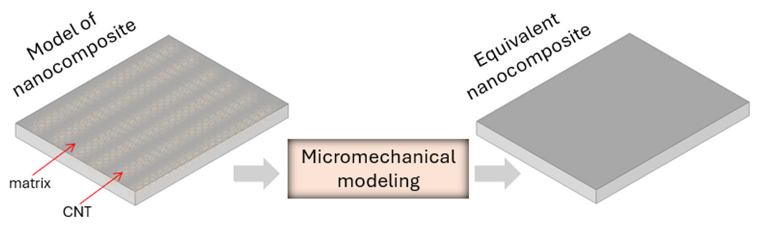
2.1. Micromechanical Modeling

In nanosystem modeling, molecular dynamics simulations are the dominant methodology [29,30,31]. However, in the analysis of mechanical properties, the global response of the nanocomposite is expected, and, thus, micromechanical modeling appears to be an appropriate approach [32]. In micromechanical modeling, the effective (average) macroscopic behavior is based on the micromechanical structure, material properties, and volume fraction of constituents.
For this study, reinforcement was assumed to be in the form of single-walled carbon nanotubes uniformly distributed in the epoxy matrix. Figure 1 schematically depicts the concept of a nanocomposite plate with uniformly distributed carbon nanotubes and is sufficient for this paper. However, for a better understanding of this topic, the reader can study the physical microscopic images of nanotubes, such as scanning electron microscopy (SEM) in 2D and X-ray computed tomography (XCT) in 3D. Examples of such images can be found in [33,34,35].
The uniform dispersion and alignment of carbon nanotubes in a polymer matrix are essential to the production of nanocomposites with improved mechanical properties [25,26,27,28]. As shown by the experimental results of Garcia et al. [11], nanocomposites with highly aligned CNTs can be expected to exhibit the properties of typical long-fiber composites. The CNT/nanocomposite with unidirectional CNTs is an orthotropic body having nine independent material constants in the constitutive equations. For aligned and uniformly distributed CNTs in the matrix, a transversely isotropic body is assumed, which reduces the number of independent constants.
The effective thickness of the CNTs is a crucial issue in estimating the material properties of CNTs. The influence of CNT thickness on the material properties is discussed, for example, in papers [36,37,38]. According to the molecular structural mechanics approach, a CNT is defined as a space frame. The covalent C-C bonds are represented as connecting beams, and the carbon atoms are connecting nodes. Tensile strength, bending stiffness, and torsional stiffness are calculated using the energy equivalence between local potential energies in computational chemistry and strain energies in structural mechanics. For example, based on the force field for benzene and assuming a C-C bond length of 0.142 nm, the cross-sectional diameter and Young’s modulus of the beam element are 0.147 nm and 5.49 TPa, respectively [39]. However, many force field constants are used in the literature to analyze CNTs, resulting in different macroscopic material properties of the nanostructure. As a result, the scatter in the wall thickness of the CNTs is presented in the range of 0.066–0.34 nm [40]. In general, the mechanical properties of CNTs tend to increase with decreasing thickness. CNTs with a small diameter of less than 1 nm and a thickness of 0.34 nm are assumed in this paper. The material data of the nanocomposite’s constituents are presented in Table 1. The current study assumes common material data for CNTs [36] and epoxy [12].
The effective material properties of CNT/nanocomposites are calculated based on Vanin’s model. Vanin [41] proposed an exact elasticity solution for a periodic system of fibers embedded in an isotropic matrix. Vanin’s elasticity approach incorporates the Hashin–Rosen and Christensen models for a transversely isotropic body. In the equations presented below (1a–1e), the isotropic plane (2–3) is perpendicular to the axial direction of the perfectly aligned carbon nanotubes
E 11 V t E t + V m E m + 8 ν t + ν m 2 V t V m G m 1 + V m + V t δ m + V m δ t 1 G m G t ,
G 12 = G 13 G m 1 + V t + V m G m G t V m + 1 + V t G m G t ,   G 23 G m 1 + V t + V m G m G t V m + 1 + V t G m G t ,
ν 21 = ν 31 ν m V t δ m + 1 V t V m 1 + V m + V t δ m + V m δ t 1 G m G t ,
1 E 22 = 1 E 33 ν 21 2 E 11 + 1 8 G m 2 V m δ m 1 + δ t 1 δ m + V t V m G m G t 1 + V m + V t δ m + V m δ t 1 G m G t + 2 G m G 23 ,
ν 23 E 22 = ν 21 2 E 11 + 1 8 G m 2 G m G 23 2 V m δ m 1 + δ t 1 δ m + V t V m G m G t 1 + V m + V t δ m + V m δ t 1 G m G t ,
where δ i = 3 4 ν i , i = t   or   m denotes nanotube and matrix, respectively; V t and V m denote volume fractions; G t and G m denote shear moduli; E t and E m denote Young’s moduli;   ν t and ν m denote Poisson’s ratios; E 11 , E 22 , and E 33 denote nanocomposite Young’s moduli; ν 21 , ν 31 ,   and   ν 23 denote nanocomposite Poisson’s ratios; and G 12 , G 13 , and G 23 denote nanocomposite shear moduli. Additionally, a nanocomposite density is computed from the rule of mixture (ROM) as
ρ = ρ t V t + ρ m 1 V t ,
The volume fractions of nanoreinforcement are typically very low. At higher volume fractions of carbon nanotubes, it has been observed that the mechanical properties of nanocomposites deteriorate due to the formation of CNT agglomerates, which act as stress concentrators. Therefore, the assumed volume fractions of nanotubes are 1%, 3%, and 5%.
The calculated effective properties of CNT/nanocomposites for selected volume fractions are listed in Table 2.

2.2. Constitutive Equations

Classical plate theory with nonlinear von Karman strains is used to characterize many materials subjected to supersonic flow, including CNT/nanocomposite plates [42], metal matrix nanocomposites [43], laminated plates [44,45,46], and shells [47]. The aero–thermoelastic instabilities of supersonic CNT/nanocomposite flat panels were studied by Asadi et al. [7] using the first-order shear deformation theory with nonlinear von Karman relations and the first-order piston theory. Maraghi [24] used the third-order shear deformation theory in the structural modeling of a CNT/nanocomposite sandwich panel to investigate flutter and divergence phenomena. Similarly, Zhang et al. [48] used third-order shear deformation theory in the piezoelectric flutter control of CNT/nanocomposite plates in supersonic airflow. The higher-order shear deformation theory was applied by Avramov et al. [49] to analyze the vibration of CNT/nanocomposite cylindrical shells in supersonic flow. A benchmark for the numerical analysis of composite plates in supersonic flow using a variety of plate theories, including classical, first-order, and higher-order theories has been presented by Muc [50].
The issue of plate flutter is studied here by considering flat, thin nanocomposite plates made of aligned and uniformly distributed carbon nanotubes in a polymer matrix and subjected to a supersonic airflow parallel to the x-axis that generates aerodynamic pressure. Characteristic dimensions in (x, y, z) coordinates are plate lengths a, b, and plate thickness h, respectively, as shown in Figure 2.
According to Kirchhoff’s plate theory (classical plate theory (CPT)), the displacement field of an arbitrary point of a plate is expressed as follows [51]
u v w = u 0 z w 0 x v 0 z w 0 y w 0 ,
where u , v , and w are displacement components in the Cartesian coordinate system (x, y, z); u 0 and v 0 are in-plane displacements in the mid-plane of the plate, and w 0 is the out-of-plane displacement. Once the displacements ( u 0 , v 0 , w 0 ) in the mid-plane are known, the displacements of any arbitrary point (x, y, z) can be computed. Assuming small strains and moderate rotations, non-zero nonlinear von Karman strains can be written in terms of the displacement field. Kinematic relations considering the nonlinear von Karman relations are written as follows [51]:
ε = ε 0 + z κ = u 0 x + 1 2 w 0 x 2 v 0 y + 1 2 w 0 y 2 u 0 y + v 0 x + w 0 x w 0 y + z 2 w 0 x 2 2 w 0 y 2 2 2 w 0 x y ,
where ε 0 and κ are membrane strain and curvature strain, respectively. For thin composite plates, the constitutive relation can be expressed as
N M =   A B B D ε 0 κ ,
where N and M are resultant forces and moments acting on a plate, which are obtained by integrating stresses and stresses multiplied by z, respectively, over plate thickness h; and A , B , and D are extensional, flexural–extensional coupling, and flexural stiffness matrices, defined as
A = h / 2 h / 2 Q d z ,   B = h / 2 h / 2 Q z d z ,   D = h / 2 h / 2 Q z 2 d z ,
where Q is the plane-stress reduced stiffness of the material, expressed in terms of engineering constants
Q = E 11 / 1 ν 12 ν 21 ν 12 E 11 / 1 ν 12 ν 21 0 ν 21 E 11 / 1 ν 12 ν 21 E 22 / 1 ν 12 ν 21 0 0 0 G 12 ,
where E 11 and E 22 are Young’s moduli in the axial direction and the transverse directions; G 12 is the shear modulus; and ν 12 and ν 21 are the major and minor Poisson’s ratios of the orthotropic layer, respectively. In the following equations, the subscript “0” is omitted for convenience.
The CNT/nanocomposite plate is assumed to be a single orthotropic layer, and according to Reddy [51], the non-zero stiffnesses are as follows
A 11 = Q 11 h ,   A 12 = Q 12 h ,   A 22 = Q 22 h ,   A 66 = Q 66 h ,   A 44 = Q 44 h ,   A 55 = Q 55 h ,   D 11 = Q 11 h 3 12 ,   D 12 = Q 12 h 3 12 ,   D 22 = Q 22 h 3 12 ,   D 66 = Q 66 h 3 12 ,
The coupling stiffness matrix B is identically zero for a single orthotropic layer.

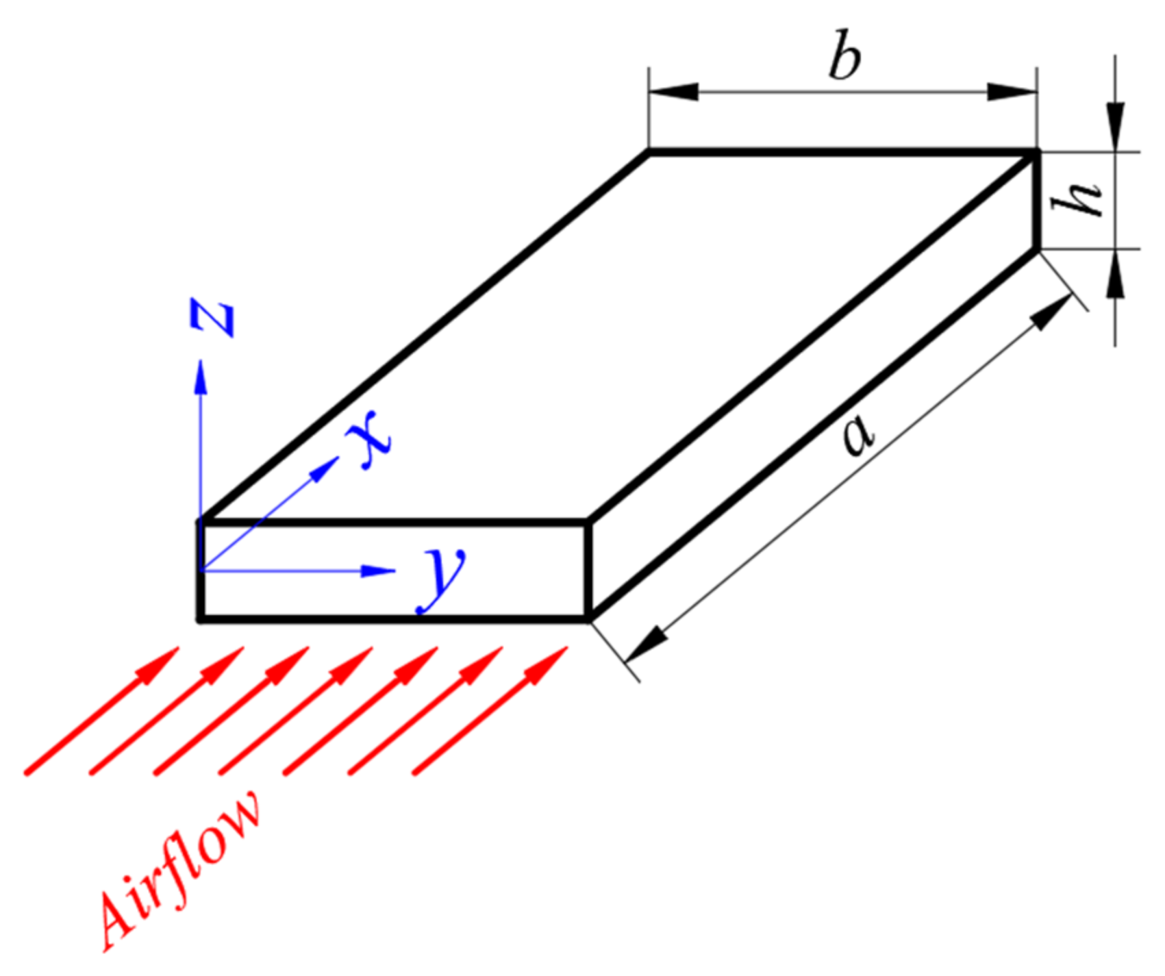
2.3. Equations of Motion

An equilibrium position in a structure occurs, according to Hamilton’s principle, when
t 1 t 2 δ U + δ W δ K d t = 0 ,
where δ U , δ W , and δ K are the virtual strain energy, the virtual work conducted by the external forces, and the virtual kinetic energy, respectively, defined as [50,51]
δ U = Ω σ i j δ ε i j d Ω ,
δ W = S Δ p δ w d S ,
δ K = Ω ρ u t 2 + v t 2 + w t 2 d Ω ,
where Ω , S ,   and   ρ denote the volume, surface, and density of the nanocomposite plate, respectively, Δ p is the aerodynamic pressure, and t is the physical time.
The aerodynamic pressure Δ p of a supersonic airflow acting on the nanocomposite plate is estimated based on first-order piston theory, where a linear function of the lateral deflection of a plate is used. Piston theory is the most commonly used method for elucidating the aerodynamic pressure acting on a body in a supersonic or hypersonic flow [21,52]. First-order piston theory is applicable to calculate the aerodynamic pressure for the supersonic airflow ( 2 M 5 ) [43]. This theory provides a computationally simple aerodynamic model for calculating aerodynamic loads, assuming that the local pressure is related to the local normal component of the air velocity, analogous to the piston moving in a cylinder [42,53]. The aerodynamic pressure field Δ p is described in terms of the out-of-plane displacement w, the air stream density ρ , the air velocity V , and Mach number M of the plate exposed to the supersonic airflow parallel to the x-axis as follows [43,54]:
Δ p = Λ w x μ w t ,
Λ = ρ V 2 / M 2 1 ,   μ = ρ V M 2 2 / M 2 1 3 / 2
Λ is the aerodynamic pressure parameter owing to the inclination of the plate concerning the flow angle direction, while represents the aerodynamic damping [43]. Since the aerodynamic damping always stabilizes the flutter [55], the aerodynamic pressure is given by
Δ p = ρ V 2 M 2 1 w x ,
Hamilton’s principle can be used to derive the equations of motion for a system. Hamilton’s system of equations leads to fourth-order differential linear equations. Since for the flat plate, the membrane and bending strains are uncoupled for the free vibration and flutter analysis, the governing relations are reduced to the study of out-of-plane deflections w only [47]. For the plate exposed to the supersonic airflow parallel to the x-axis (the airflow angle is equal to 0°) the fundamental relation can be written as [46]
D 11 4 w x 4 + 2 D 12 + 2 D 66 4 w x 2 y 2 + D 22 4 w y 4 N x 0 2 w x 2 + N y 0 2 w y 2 + ρ h 2 w t 2 + Λ w x + μ h w t = 0 ,
The problem is reduced to finding out the eigenvalues and corresponding mode shapes of the system for a given value of the aerodynamic pressure parameter Λ .
Assuming that the pair of edges in the y-direction is simply supported, the solution of Equation (13) is looking for the out-of-plane deflection w in the form of a single Fourier series
w y = B n s i n n π y b ,         n = 1 ,   2 ,   ,
where n is the wave number in y-direction and B n are constants. The solution is assumed to be in the form
w = e r x ,  
where r denotes the roots of the characteristic equation. Thus, the solution is a typical eigenvalue problem. Using the above relations and eliminating the damping, Equation (13) is reduced to a one-dimensional problem with an unknown parameter r in the form
D 11 r 4 a 4 2 D 12 + 2 D 66 r 2 a 2 n π b 2 + D 22 n π b 4 N x 0 r 2 a 2 + N y 0 n π b 2 ρ h ω 2 +   Λ r a = 0 ,
where ω denotes frequency. The solution of the flutter problem (Equation (16)) is related to the applied boundary conditions along the x-axis. The boundary conditions considered here are:
  • Simply supported: w = w” = 0 on x = 0 and x = a;
  • Clamped supported: w = w’ = 0 on x = 0 and x = a.
The divergence instability is present for ω = 0, and the flutter instability occurs for ω ≠ 0 [53]. The characteristic Equation (16) for the CPT plate can be written in a more convenient way according to Bolotin [56]
r 2 π 2 k 2 + β r λ = 0 ,
where
k = a 2 m 2 D 11 D 12 + 2 D 66 n b 2 + N x 0 2 π 2 , β = a 3 m 3 D 11 Λ , λ = a 4 m 4 D 11 ρ h ω 2 D 22 n π b 4 N y 0 n π b 2 4 π 4 k 2 ,
and m is the wave number in the x-direction. The solution of the characteristic Equation (17) is a function of only two variables and is written as
r 1 , 2 = μ ± i ν ,    r 3 , 4 = μ ± ν 2 4 μ 2 ,   i = 1 .
Moreover, the parameters β and λ can be expressed using μ and ν as
β = 4 μ ν 2 μ 2 + k π 2 ,     λ = k 2 π 4 + μ b 2 + ν 2 ν 2 3 μ 2 + 2 k π 2 .
Considering boundary conditions, Bolotin [56] gave the explicit form of the determinant in terms of the variables μ and ν
  • For a simply supported plate (SSSS)
Δ k , λ , β = μ 2 c o s h 2 μ c o s h ν 2 2 μ 2 + 2 k π 2 c o s ν + ν 2 μ 2 k π 2 2 + 2 μ 2 μ 2 k π 2 ν 2 2 μ 2 + 2 k π 2 s i n ν 2 ν s i n h ν 2 2 μ 2 + 2 k π 2 = 0 .
  • For a clamped plate (SCSC)
Δ k , λ , β = c o s h 2 μ c o s h ν 2 2 μ 2 + 2 k π 2 c o s ν + k π 2 3 μ 2 ν 2 2 μ 2 + 2 k π 2 s i n ν ν s i n h ν 2 2 μ 2 + 2 k π 2 = 0 .
The eigenvalue curve can be drawn assuming the arbitrary value of constant k in the coordinates (μ, ν).

3. Results and Discussion

3.1. Modeling Verification

Before the detailed analysis of the CNT/nanocomposite plates, the step-by-step analysis of the simply supported isotropic square plate is verified. The calculated results for the square isotropic plate were compared with literature data [45,55,57,58]. The verification showed excellent agreement with existing data reported in the literature.

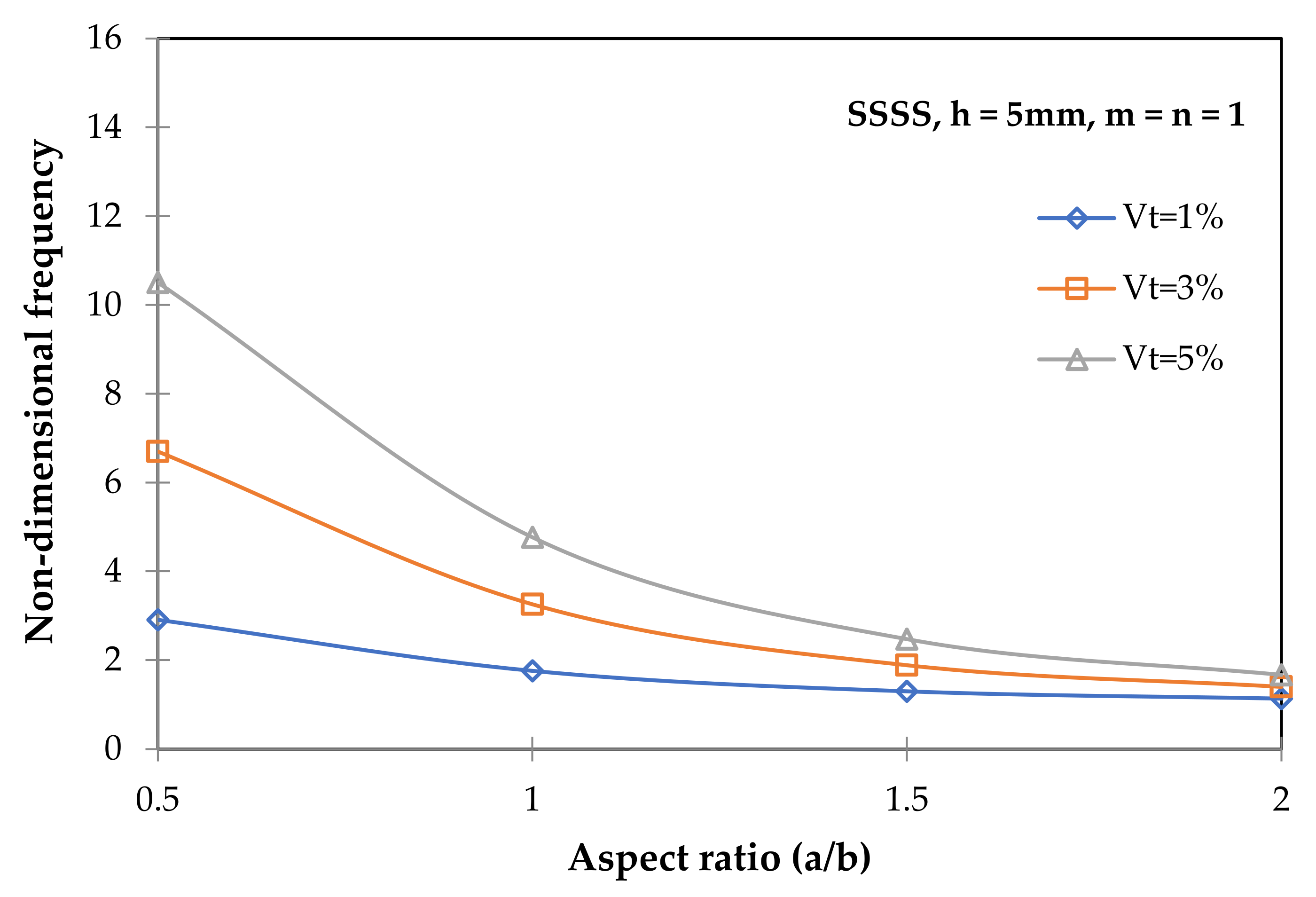
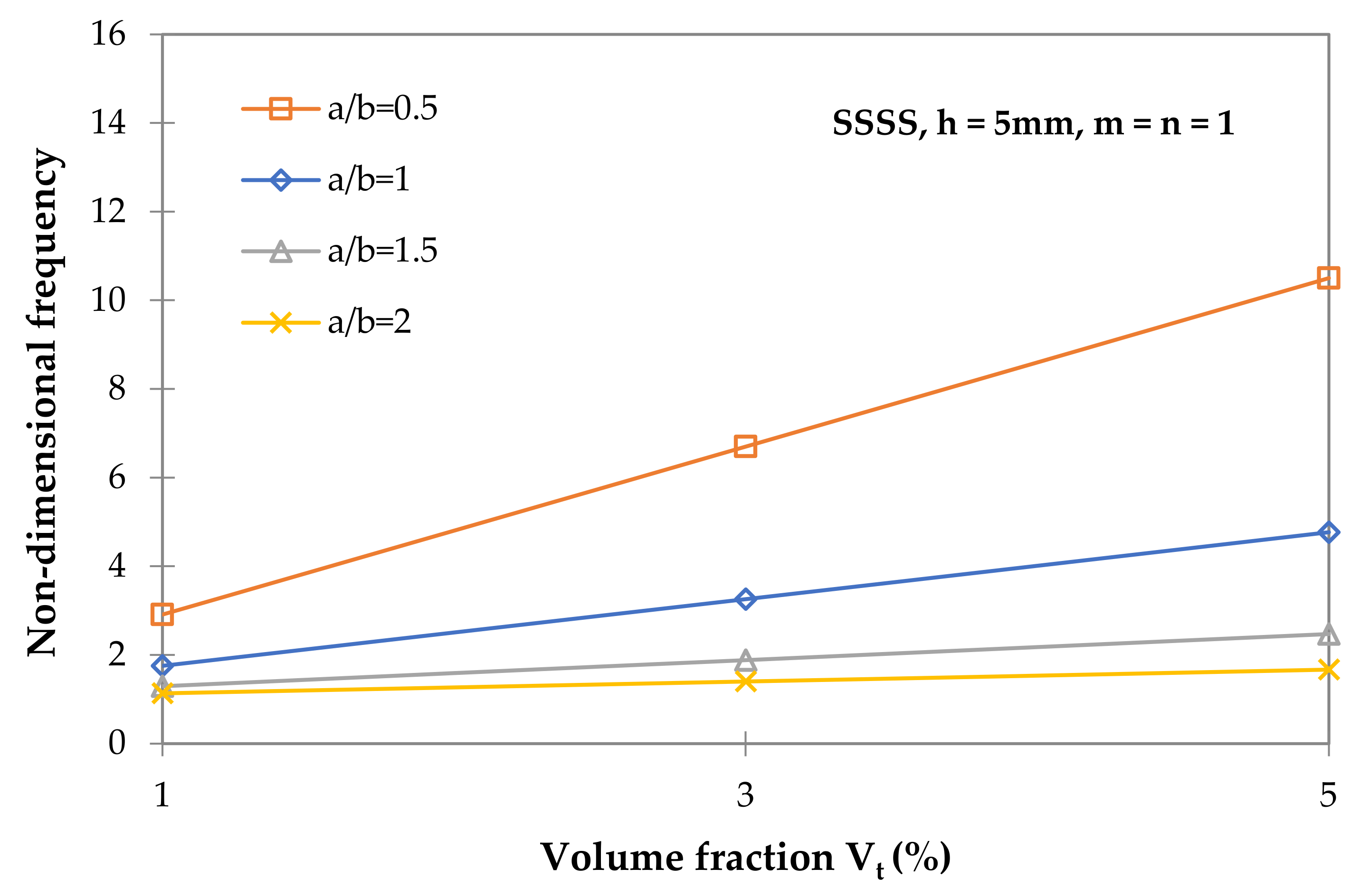
3.2. Free Vibration Analysis of CNT/Nanocomposite Plates

Various geometric parameters and volume fractions are considered in the free vibration analysis of CNT/nanocomposite plates. Plates with thicknesses of 2 mm and 5 mm, assuming the width-to-thickness ratios a/h = 200 (h = 5 mm) and a/h = 500 (h = 2 mm) with different aspect ratios of the plates, i.e., a/b = 0.5; 1; 1.5; and 2, were studied.
Figure 3 shows the variation of the non-dimensional fundamental frequency of various simply supported nanocomposite plates as a function of the plate aspect ratio. The increase in the aspect ratio results in the decrease in the fundamental frequency for all analyzed volume fractions of the nanotubes. Lei et al. [37] also observed a similar degradation of the nanocomposite non-dimensional frequency with increasing plate aspect ratios. The results are in good agreement. Lei et al. [37] reported a 58% reduction in non-dimensional frequency comparing SSSS square (a/b = 1) and rectangular plates (a/b = 2), and current predictions indicate a 64% reduction.
As the volume fraction of CNTs grows, the natural frequency increases, as shown in Figure 4. For the square plate (a/b = 1), a 2.7-fold improvement in frequency was observed when the volume fraction of CNTs was increased from 1% to 5%. It can be seen that the higher the aspect ratio, the smaller the effect of the volume fraction of CNTs on the frequencies. For the rectangular plates, comparing 5% to 1% CNTs for a/b = 1.5 and a/b = 2, there is a 90% and 46% increase in the fundamental frequency, respectively. This is a much lower value than the 2.7-fold increase for the square nanocomposite plate.
Figure 5 shows the fundamental frequency of the SSSS plate as a function of the aspect ratio. The different volume fractions of CNTs and plate thicknesses have been considered. The thinner the nanocomposite plate, the lower the frequency observed. However, the discrepancies tend to worsen as the aspect ratio of the plate increases. The higher the volume fraction, the higher the frequency. The square plate’s increase is approximately 65% when comparing 1% and 5% volume fractions. Comparable observations were presented by Wang et al. [19] for FG CNT/nanocomposite plates with uniform distribution of CNTs where comparable aspect ratios were used.
Figure 6 and Figure 7 show the non-dimensional frequency vs. CNT volume fraction of SSSS square and rectangular (a/b = 2) nanocomposite plates for the first five modes. An observation of the trends and results shown in Figure 3, Figure 4, Figure 5, Figure 6 and Figure 7 reveals some interesting phenomena. For all modes (assuming n = 1), the frequencies are higher for the square plate. The increase in frequency is also observed as the volume fraction of CNTs increases. As expected, the increase in volume fraction causes the increase of non-dimensional frequencies (Figure 6), and the increase in the aspect ratio shows the decrease in eigenfrequencies (Figure 3). Similar thickness-to-width ratios of thin CNT/nanocomposite plates (h/a = 0.005 and h/a = 0.002) and ranges of aspect ratios analyzed (0.5, 1.0, 1.5, 2.0) were studied by Wang et al. [19]. Wang et al. [19] also observed a decrease in frequency with an increasing aspect ratio. It should be noted here that Wang et al. [19] analyzed much higher volume fractions of CNTs (11%,14%, and 17%) compared to the present analysis, which focused on small fractions (1%, 3%, 5%). The choice of such volume fractions of CNTs was dictated by descriptions of experimental work on the difficulty of obtaining uniform distribution of CNTs in the matrix structure at higher fractions and the tendency of CNTs to form agglomerates at higher volume fractions. The proposed volume fractions of CNTs were adopted based on the experimental work of Arena et al. [8], where nanocomposites with low fractions of CNTs were analyzed. To the author’s knowledge, there are no a priori imposed criteria for selecting the CNT volume fraction.
The paper by Wang et al. [19] reported that there was no effect of increasing the thickness-to-width ratio on the natural frequencies of nanocomposite plates. The values of the frequencies were at a constant level, but the authors did not address this, and the results were given only for one volume fraction of CNTs (11%). In the current analysis, it was observed that an increase in thickness at a constant width and length has an effect on the increase in eigenfrequencies, and this is a constant increase (Figure 5). For all CNT fractions analyzed, a constant 2.5-fold increase in the fundamental frequency was obtained for a thickness of 5 mm compared to the values for a thickness of 2 mm. In this sense, the present frequency characteristics can be considered similar to those reported in the work of Wang et al. [19]. In general, an increase in plate thickness causes an increase in natural frequencies.
This indicates that even much lower-volume fractions of nanotubes in composite plates (almost 10 times lower than in the work of, e.g., Wang et al. [19] or Shen et al. [14]), allow us to obtain similar dynamic properties of the structure. In addition, selected nanotube fractions in the range of 1–5% CNT allow for a uniform distribution of CNT and are likely to form a more stable CNT-polymer system than higher CNT fractions. The most important thing from the current analyses is that low-volume fractions of CNT percentages can effectively increase the natural frequencies of nanocomposite plates.

3.3. Flutter Analysis of CNT/Nanocomposite Plates

The present analysis of CNT/nanocomposite flutter phenomena considers mainly the influence of CNT volume fractions and BC. The aeroelastic analysis of square CNT/nanocomposite plates is performed for fully simply supported (SSSS) and clamped (SCSC) structures, assuming an angle flow of 0° and ignoring the damping.
The influence of boundary conditions and CNT volume fraction (k parameter) on the eigenvalue curves is investigated in the first part of the flutter analysis. The effect of the boundary conditions is shown in Figure 8, where the eigenvalue curves for simply supported and clamped CNT/nanocomposite plates are plotted. The contour plot of the eigenvalue curves is drawn according to Equations (21) and (22). The square nanocomposite plate with 1%vol. of nanoreinforcement and 2 mm thickness was used. In the plots, Re denotes the real part of r, while Im is the imaginary part. It can be seen how the boundary conditions determined the shape and position of the eigenvalue curves. The curve for the clamped nanocomposite plate is shifted to the lower pressure value.
Because eigenvalue plots are functions of the k parameter, changing this value can change the shape of the curves. The change in the eigenvalue curves affects the possible solution to the flutter problem. The comparison between the eigenvalue curve for isotropic and orthotropic square plates is shown in Figure 9. It is worth pointing out, that the parameter k is equal to 1 for the isotropic plate, while for the nanocomposite plate with 1%vol. of CNT (orthotropic plate) is much lower and equal to 0.257. For the nanocomposite plate, the eigenvalue curve is narrower and moves down. Figure 9 considers the square clamped plates (SCSC). Moreover, considering the orthotropic plates, the influence of the CNT volume fraction on the eigenvalue curve was analyzed. Figure 10 shows the results of simply supported nanocomposite plates with different volume fractions of CNTs. It can be seen that the higher the volume fraction is, the narrower the eigencurves are. However, the discrepancies are less visible for higher volume fractions of CNTs. For SSSS plates, the orthotropic eigencurves lie within the isotropic one (SSSS 0% CNT), while for SCSC plates, the movement is observed in two directions, as shown in Figure 9. Based on the results presented in Figure 8 and Figure 10, it is evident that the boundary conditions have a higher influence on the eigenvalue curve than the volume fraction of CNT.
The contour plot of non-dimensional pressure and non-dimensional frequency λ for 1% CNT/nanocomposite plate is presented in Figure 11. The increase of the real part of r, the non-dimensional pressure increase, and the non-dimensional frequency λ decrease are visible. The vertical axis (r-Im) correspondends to a situation when the critical aerodynamic pressure β = 0. The coalescence point can be found analytically by plotting the non-dimensional pressure, non-dimensional frequency, and eigenvalue curves.
The method of the analytical (graphical) derivation of the critical aerodynamic pressure for the first mode is shown in Figure 12. The graphical representation considers the case of a simply supported square nanocomposite plate with 1% vol. of CNTs. The critical pressure contour is tangent to the eigenvalue curve (coalescent point). The critical frequency was searched as the intersection at the coalescent point. The coalescent point is strictly determined by the coordinates ( μ ,   ν ) as depicted in Equations (17)–(20). The above point intersects the eigenvalue curve. The left side of the curve shows the pre-flutter behavior, while the right side is associated with the post-flutter behavior. The pre-flutter behavior starts at β = 0 and ends at the coalescent point.
The same approach, as shown in Figure 12, was used to construct the supersonic flutter plots for the other nanocomposites analyzed. The results of critical aerodynamic pressure and coalescence frequency are presented in Table 3. The values of and λ depend on the parameter k, which is directly related to the natural vibration modes. It was observed that for higher volume fractions of CNTs, the critical pressure and coalescence frequency are lowered. However, the same critical frequency for Vt = 3% and 5% was observed in the graphical constructions. The shape of the eigenvalue curves shown in Figure 10 is responsible for the coincidence of the non-dimensional frequency and the small differences in the non-dimensional critical pressure. The shape and position of the eigenvalue curve were almost the same for the cases of 3% and 5% CNTs.

4. Conclusions

The paper was dedicated to the study of the free vibration and flutter characteristics of carbon nanotube-reinforced composite plates, with the core issue being the in-depth analysis of the eigenfrequencies and flutter of classical carbon nanotube/nanocomposite thin plates in supersonic airflow environments. It was assumed that the reinforcing material of the thin plate is uniformly distributed and aligned in the polymer matrix with the low-volume fraction of carbon nanotubes. The analysis of free vibrations and supersonic flutter was presented considering the volume fraction of CNTs, geometrical parameters, and boundary conditions. Micromechanical modeling was applied to predict the mechanical properties of nanocomposites.
The analyses performed led to the following conclusions:
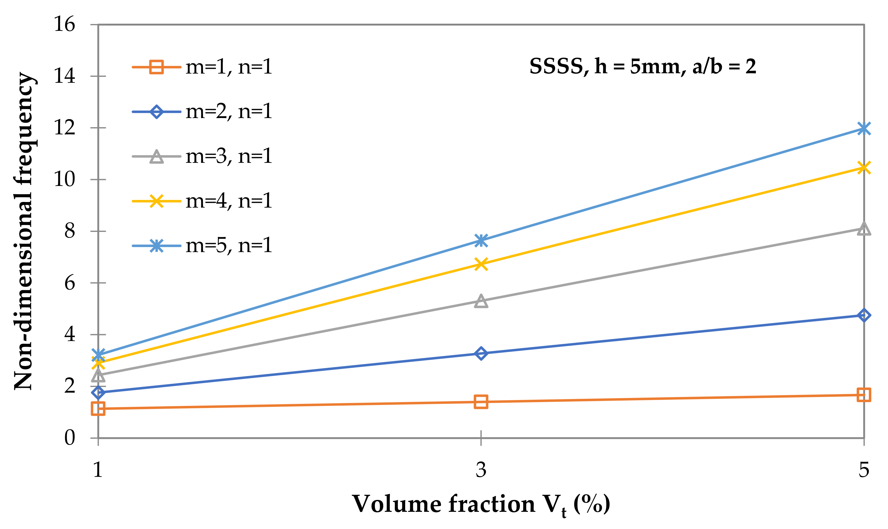
  • For all nanotube volume fractions analyzed, increasing the aspect ratio decreases the fundamental frequency. When the volume fraction of CNTs was increased from 1% to 5%, a 2.7-fold improvement in frequency was observed. The effect of the volume fraction of CNTs on frequencies decreases with increasing aspect ratios.
  • A lower frequency was observed with thinner nanocomposite sheets. However, the differences decrease as the aspect ratio of the plate increases. The growth in thickness at a constant width-to-length ratio influenced the increase in natural frequencies, and it was a constant increase of 2.5-fold.
  • It was shown that even low-volume fractions of nanotubes can effectively increase the natural frequencies of nanocomposite plates.
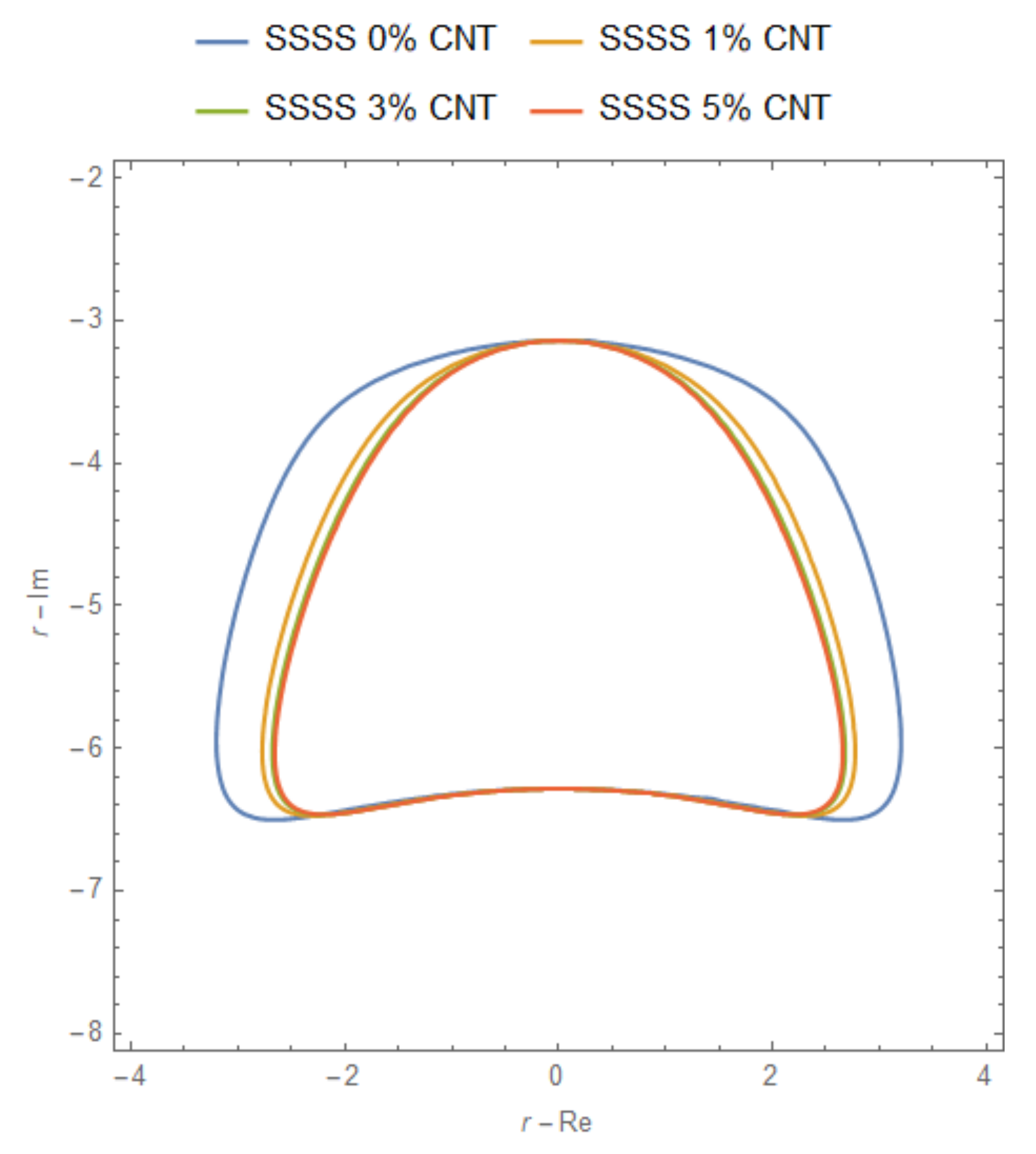
  • It was shown that the higher the volume fraction of CNTs, the narrower the eigenvalue curves. However, the discrepancies are less pronounced for higher CNT volume fractions than isotropic cases.
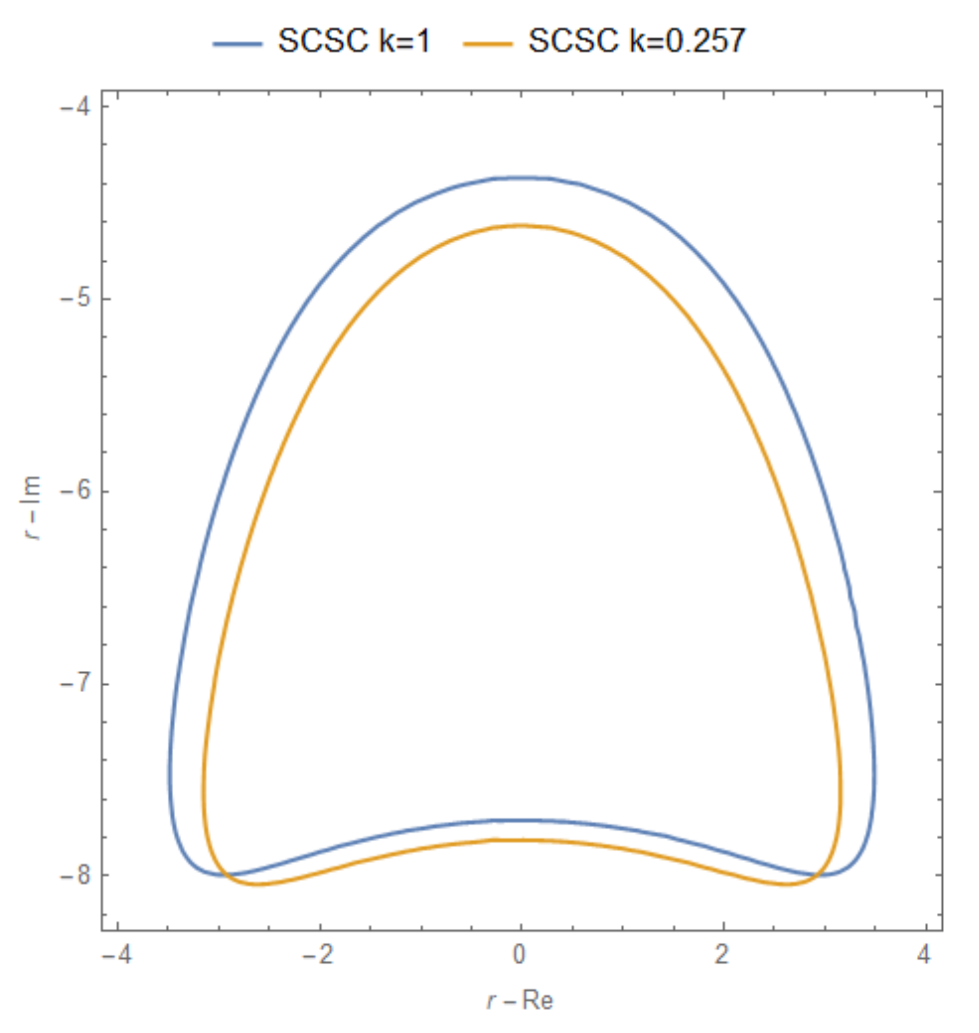
  • It can be seen that the boundary conditions affect the eigenvalue curve more than the CNT volume fraction.
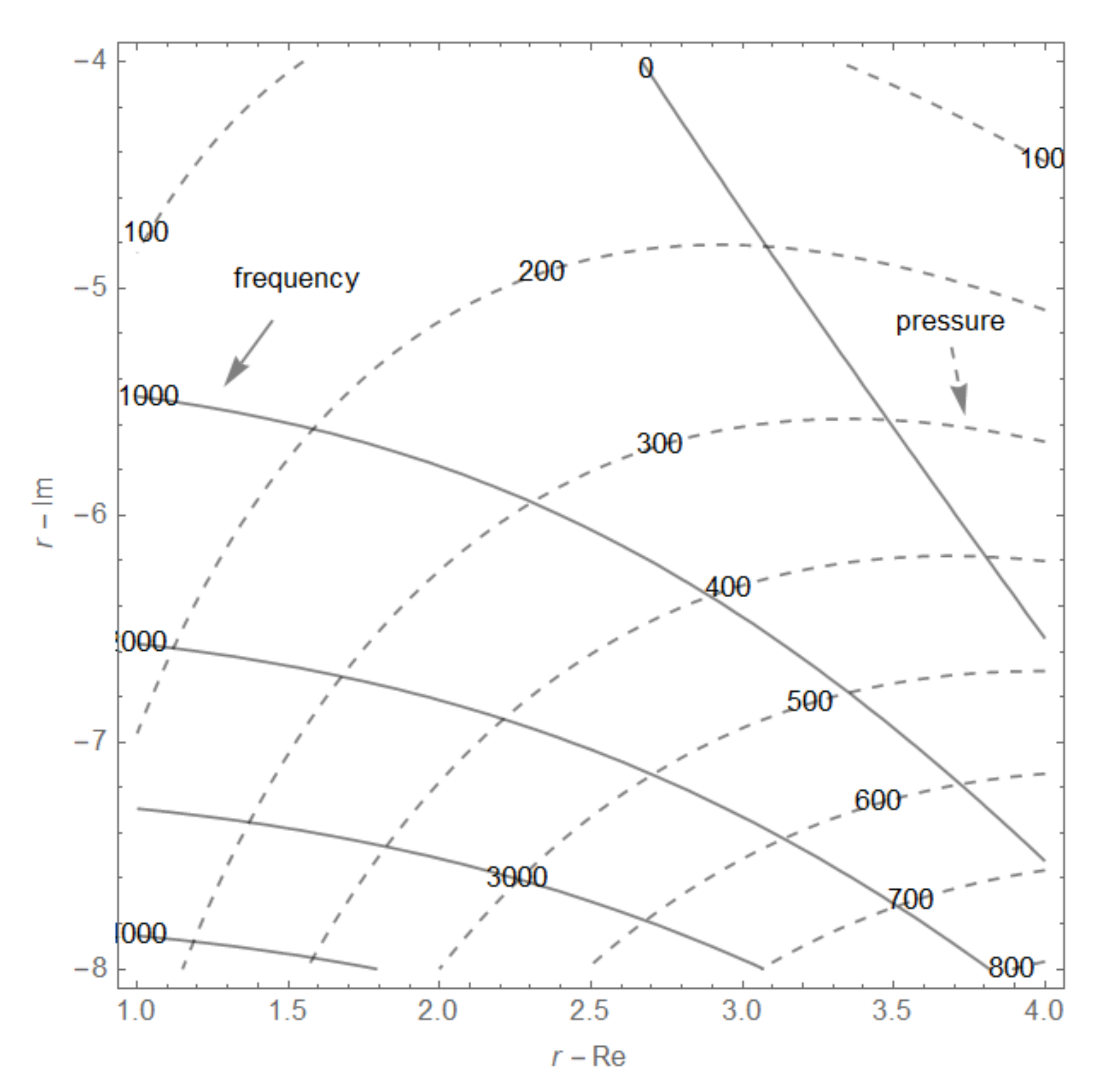
  • The possible solution to the flutter problem was mainly influenced by the changes in the eigenvalue curves. The coincidence or small differences in the position of the coalescence point for higher volume fractions of CNTs were caused by the shape of the eigenvalue curves. For the higher volume fraction of CNTs, there was almost the same shape and position of the eigenvalue curve.
The current study demonstrated the applicability of the analytical (graphical) method in predicting the pre-flutter and post-flutter behavior of nanocomposite plates. It was presented as plots of non-dimensional pressure, non-dimensional frequency, and eigenvalue curves that can be used to analytically find the coalescence point. The extension of the current work should take into account the damping analysis of nanocomposites with CNTs, which was proposed in [10,18].

Funding

This research received no external funding.

Institutional Review Board Statement

Not applicable.

Informed Consent Statement

Not applicable.

Data Availability Statement

Data are contained within the article.

Conflicts of Interest

The author declares no conflict of interest.

References

  1. Ali, Z.; Yaqoob, S.; Yu, J.; D’Amore, A. Critical review on the characterization, preparation, and enhanced mechanical, thermal, and electrical properties of carbon nanotubes and their hybrid filler polymer composites for various applications. Compos. C 2024, 13, 100434. [Google Scholar] [CrossRef]
  2. Liu, Q.; Fan, G.; Tan, Z.; Saba, F.; Guo, Q.; Xiong, D.; Su, Y.; Li, Z.; Zhang, D. Effect of thermomechanical treatment and length-scales on spatial distribution of CNTs in Al matrix. Carbon 2022, 190, 384–394. [Google Scholar] [CrossRef]
  3. Li, W.; Feng, Z.; Weiguang, S.; Xingyuan, X.; Anqing, L.; Yunlun, L.; Chonghai, X.; Yu, S. Green Manufacturing of Flexible Sensors with a Giant Gauge Factor: Bridging Effect of CNT and Electric Field Enhancement at the Percolation Threshold. ACS Appl. Mater. Interfaces 2022, 14, 26024–26033. [Google Scholar]
  4. Yang, H.; Yuan, L.; Yao, X.F.; Zheng, Z.; Fang, D.N. Monotonic strain sensing behavior of self-assembled carbon nanotubes/graphene silicone rubber composites under cyclic loading. Compos. Sci. Technol. 2020, 200, 108474. [Google Scholar] [CrossRef]
  5. Chai, Y.; Gao, W.; Ankay, B.; Li, F.; Zhang, C. Aeroelastic analysis and flutter control of wings and panels: A review. Int. J. Mech. Syst. Dyn. 2021, 1, 5–34. [Google Scholar] [CrossRef]
  6. Liew, K.M.; Lei, Z.X.; Zhang, L.W. Mechanical analysis of functionally graded carbon nanotube reinforced composites: A review. Compos. Struct. 2015, 120, 90–97. [Google Scholar] [CrossRef]
  7. Asadi, H.; Souri, M.; Wang, Q. A numerical study on flow-induced instabilities of supersonic FG-CNT reinforced composite flat panels in thermal environments. Compos. Struct. 2017, 171, 113–125. [Google Scholar] [CrossRef]
  8. Arena, A.; Talóa, M.; Snyder, M.P.; Lacarbonara, W. Enhancing flutter stability in nanocomposite thin panels by harnessing CNT/polymer dissipation. Mech. Res. Commun. 2020, 104, 103495. [Google Scholar] [CrossRef]
  9. Chwał, M.; Muc, A. Design of reinforcement in nano and microcomposites. Materials 2019, 12, 1474. [Google Scholar] [CrossRef]
  10. Lin, R.M.; Lu, C. Modeling of interfacial friction damping of carbon nanotube-based nanocomposites. Mech. Syst. Signal Process. 2010, 24, 2996–3012. [Google Scholar] [CrossRef]
  11. Garcia, E.J.; Hart, A.J.; Wardle, B.L.; Slocum, A.H. Fabrication and nanocompression testing of aligned carbon-nanotube–polymer nanocomposites. Adv. Mater. 2007, 19, 2151–2156. [Google Scholar] [CrossRef]
  12. Fidelus, J.D.; Wiesel, E.; Gojny, F.H.; Schulte, K.; Wagner, H.D. Thermo-mechanical properties of randomly oriented carbon/epoxy nanocomposites. Compos. Part A 2005, 36, 1555–1561. [Google Scholar] [CrossRef]
  13. Shen, S.H. Nonlinear bending of functionally graded carbon nanotube-reinforced composite plates in thermal environments. Compos. Struct. 2009, 91, 9–19. [Google Scholar] [CrossRef]
  14. Shen, H.S.; Xiang, Y. Thermal postbuckling of nanotube-reinforced composite cylindrical panels resting on elastic foundations. Compos. Struct. 2015, 123, 383–392. [Google Scholar] [CrossRef]
  15. Jonsson, E.; Riso, C.; Lupp, C.A.; Cesnik, C.E.S.; Martins, J.R.R.A.; Epureanu, B.I. Flutter and post-flutter constraints in aircraft design optimization. Prog. Aerosp. Sci. 2019, 109, 100537. [Google Scholar] [CrossRef]
  16. Muc, A.; Flis, J.; Augustyn, M. Optimal design of plated/shell structures under flutter constraints—A literature review. Materials 2019, 12, 4215. [Google Scholar] [CrossRef]
  17. Kameyama, M.; Fukunaga, H. Optimum design of composite plate wings for aeroelastic characteristics using lamination parameters. Comput. Struct. 2007, 85, 213–224. [Google Scholar] [CrossRef]
  18. Formica, G.; Talo, M.; Lacarbonara, W. Nonlinear modeling of carbon nanotube composites dissipation due to interfacial stick–slip. Int. J. Plast. 2014, 53, 148–163. [Google Scholar] [CrossRef]
  19. Wang, M.; Li, Z.M.; Qiao, P. Semi-analytical solutions to buckling and free vibration analysis of carbon nanotube-reinforced composite thin plates. Compos. Struct. 2016, 144, 33–43. [Google Scholar] [CrossRef]
  20. Guo, H.; Li, M.; Żur, K.K.; Yuan, J.; Wu, X. Flutter of carbon-based nanohybrid composite panels. Thin-Walled Struct. 2023, 188, 110828. [Google Scholar] [CrossRef]
  21. Liu, C.; Xie, C.; Meng, Y.; Bai, L. Experimental and Numerical Flutter Analysis Using Local Piston Theory with Viscous Correction. Aerospace 2023, 10, 870. [Google Scholar] [CrossRef]
  22. Huang, K.; Guo, H.; Qin, Z.; Cao, S.; Chen, Y. Flutter analysis of laminated composite quadrilateral plates reinforced with graphene nanoplatelets using the element-free IMLS-Ritz method. Aerosp. Sci. Technol. 2020, 103, 105915. [Google Scholar] [CrossRef]
  23. Camacho, P.; Akhavan, H.; Ribeiro, P. Linear aeroelastic analysis of cantilever hybrid composite laminated plates with curvilinear fibres and carbon nanotubes. Compos. Struct. 2021, 266, 113765. [Google Scholar] [CrossRef]
  24. Maraghi, Z.K. Flutter and divergence instability of nanocomposite sandwich plate with magnetostrictive face sheets. J. Sound. Vib. 2019, 457, 240–260. [Google Scholar] [CrossRef]
  25. Khan, S.U.; Pothnis, J.R.; Kim, J.-K. Effects of carbon nanotube alignment on electrical and mechanical properties of epoxy nanocomposites. Compos. Part. A Appl. Sci. Manuf. 2013, 49, 26–34. [Google Scholar] [CrossRef]
  26. Liu, L.; Han, J.; Xu, L.; Zhou, J.; Zhao, C.; Ding, S.; Shi, H.; Xiao, M.; Ding, L.; Ma, Z.; et al. Aligned, high-density semiconducting carbon nanotube arrays for high-performance electronics. Science 2020, 368, 850–856. [Google Scholar] [CrossRef]
  27. Guan, L.-Z.; Tang, L.-C. Dispersion and Alignment of Carbon Nanotubes in Polymer Matrix. In Handbook of Carbon Nanotubes; Springer: Berlin/Heidelberg, Germany, 2021; pp. 1–35. [Google Scholar]
  28. Yin, Z.; Ding, A.; Zhang, H.; Zhang, W. The Relevant Approaches for Aligning Carbon Nanotubes. Micromachines 2022, 13, 1863. [Google Scholar] [CrossRef]
  29. Talapatra, A.; Datta, D. A review of the mechanical, thermal and tribological properties of graphene reinforced polymer nanocomposites: A molecular dynamics simulations methods. Polym. Bull. 2023, 80, 2299–2328. [Google Scholar] [CrossRef]
  30. Hou, G.; Ren, R.; Shang, W.; Weng, Y.; Liu, J. Molecular dynamics simulation of polymer nanocomposites with supramolecular network constructed via functionalized polymer end-grafted nanoparticles. Polymers 2023, 15, 3259. [Google Scholar] [CrossRef]
  31. Muc, A.; Barski, M. Design of particulate-reinforced composite materials. Materials 2018, 11, 234. [Google Scholar] [CrossRef]
  32. Chwał, M.; Muc, A. Buckling and free vibrations of nanoplates—Comparison of nonlocal strain and stress approaches. Appl. Sci. 2019, 9, 1409. [Google Scholar] [CrossRef]
  33. Huang, Y.-J.; Natarajan, S.; Zhang, H.; Guo, F.-Q.; Xu, S.-L.; Chen, Z.; Zheng, Z.-S. CT image-driven computational framework for investigating complex 3D fracture in mesoscale concrete. Cem. Concr. Compos. 2023, 143, 105270. [Google Scholar] [CrossRef]
  34. Kimiyoshi, N.; Chiemi, N.; Keiichi, S.; Yoshinobu, S.; Yoku, I. Tensile properties and fracture behavior of carbon nanotube-sheets/carbon fibers epoxy-impregnated bundle composites. Polym. Polym. Compos. 2022, 30, 1–11. [Google Scholar]
  35. Pei, N.; Shang, J.; Bond, L.J. Analysis of Progressive Tensile Damage of Multi-walled Carbon Nanotube Reinforced Carbon Fiber Composites by Using Acoustic Emission and Micro-CT. J. Nondestruct. Eval. 2021, 40, 51. [Google Scholar] [CrossRef]
  36. Chwał, M. Nonlocal analysis of natural vibrations of carbon nanotubes. J. Mater. Eng. Perform. 2018, 27, 6087–6096. [Google Scholar] [CrossRef]
  37. Lei, Z.X.; Liew, K.M.; Yu, J.L. Free vibration analysis of functionally graded carbon nanotube-reinforced composite plates using the element-free kp-Ritz method in thermal environment. Compos. Struct. 2013, 106, 128–138. [Google Scholar] [CrossRef]
  38. Wang, Z.X.; Shen, H.S. Nonlinear dynamic response of nanotube-reinforced composite plates resting on elastic foundations in thermal environments. Nonlinear Dyn. 2012, 70, 735–754. [Google Scholar] [CrossRef]
  39. Shokrieh, M.M.; Rafiee, R. Prediction of Young’s Modulus of Graphene Sheets and Carbon Nanotubes Using Nanoscale Continuum Mechanics Approach. Mater. Des. 2010, 31, 790–795. [Google Scholar] [CrossRef]
  40. Paris, O. (Ed.) Structure and Multiscale Mechanics of Carbon Nanomaterials; Springer: Berlin/Heidelberg, Germany, 2016. [Google Scholar]
  41. Vanin, G.A. Micro-Mechanics of Composite Materials; Nauka Dumka: Kiev, Ukraine, 1985. [Google Scholar]
  42. Fazelzadeh, S.A.; Pouresmaeeli, S.; Ghavanloo, E. Aeroelastic characteristics of functionally graded carbon nanotube-reinforced composite plates under a supersonic flow. Comput. Methods Appl. Mech. Eng. 2015, 285, 714–729. [Google Scholar] [CrossRef]
  43. Hussein, O.S.; Mulani, S.B. Nonlinear aeroelastic stability analysis of in-plane functionally graded metal nanocomposite thin panels in supersonic flow. Thin-Walled Struct. 2019, 139, 398–411. [Google Scholar] [CrossRef]
  44. Kouchakzadeh, M.A.; Rasekh, M.; Haddadpour, H. Panel flutter analysis of general laminated composite plates. Compos. Struct. 2010, 92, 2906–2915. [Google Scholar] [CrossRef]
  45. Li, J.; Narita, Y. Analysis and optimal design for supersonic composite laminated plate. Compos. Struct. 2013, 101, 35–46. [Google Scholar] [CrossRef]
  46. Muc, A.; Flis, J. Closed form solutions—Analysis and optimal design of supersonic composite laminated flat plates considering mechanical and thermal effects. Compos. Struct. 2019, 230, 111491. [Google Scholar] [CrossRef]
  47. Bakhtiari, M.; Lakis, A.A.; Kerboua, Y. Nonlinear supersonic flutter of truncated conical shells. J. Mech. Sci. Technol. 2020, 34, 1375–1388. [Google Scholar] [CrossRef]
  48. Zhang, L.W.; Song, Z.G.; Liew, K.M. Computation of aerothermoelastic properties and active flutter control of CNT reinforced functionally graded composite panels in supersonic airflow. Comput. Methods Appl. Mech. Eng. 2016, 300, 427–441. [Google Scholar] [CrossRef]
  49. Avramov, K.V.; Chernobryvko, M.; Uspensky, B.; Seitkazenova, K.K.; Myrzaliyev, D. Self-sustained vibrations of functionally graded carbon nanotubes-reinforced composite cylindrical shells in supersonic flow. Nonlinear Dyn. 2019, 98, 1853–1876. [Google Scholar] [CrossRef]
  50. Muc, A. Transverse shear effects in supersonic flutter problems for composite multilayered rectangular plates—Benchmark for numerical analysis. Compos. Part C 2020, 1, 100001. [Google Scholar] [CrossRef]
  51. Reddy, J.N. Mechanics of Laminated Composite Plates and Shells; CRC Press: Boca Raton, FL, USA, 2003. [Google Scholar]
  52. Meijer, M.C.; Dala, L. A generalized formulation and review of piston theory for airfoils. AIAA J. 2016, 54, 17–27. [Google Scholar] [CrossRef]
  53. Arani, A.G.; Soleymani, T. Size-dependent vibration analysis of a rotating MR sandwich beam with varying cross section in supersonic airflow. Int. J. Mech. Sci. 2019, 151, 288–299. [Google Scholar] [CrossRef]
  54. Chen, J.; Han, R.; Liu, D.; Zhang, W. Active flutter suppression and aeroelastic response of functionally graded multilayer graphene nanoplatelet reinforced plates with piezoelectric patch. Appl. Sci. 2022, 12, 1244. [Google Scholar] [CrossRef]
  55. Prakash, T.; Ganapathi, M. Supersonic flutter characteristics of functionally graded flat panels including thermal effects. Compos. Struct. 2006, 72, 10–18. [Google Scholar] [CrossRef]
  56. Bolotin, V.V. Nonconservative Problems of the Theory of Elastic Stability; Pergamon Press: Oxford, UK, 1963. [Google Scholar]
  57. Lin, K.J.; Lu, P.J.; Tarn, J.Q. Flutter analysis of composite panels using high precision finite elements. Comput. Struct. 1989, 33, 561–574. [Google Scholar]
  58. Guo, H.; Żur, K.K.; Ouyang, X. New insights into the nonlinear stability of nanocomposite cylindrical panels under aero-thermal loads. Compos. Struct. 2023, 303, 116231. [Google Scholar] [CrossRef]
Figure 1. The concept of the micromechanical modeling of the equivalent nanocomposite with aligned carbon nanotubes.
Applsci 15 01140 g001
Figure 2. The mechanical model of the equivalent nanocomposite plate subjected to a supersonic airflow in the x-direction. The z-coordinate is determined from the mid-plane of the plate.
Applsci 15 01140 g002
Figure 3. Variation of the non-dimensional fundamental frequency of the simply supported nanocomposite plate as a function of the aspect ratio of the plates (h = 5 mm, m = n = 1) for various volume fractions of CNTs (1%, 3%, and 5%).
Applsci 15 01140 g003
Figure 4. Variation of the non-dimensional fundamental frequency of the simply supported nanocomposite plate as a function of the volume fractions of CNTs for the various aspect ratios of the plates (h = 5 mm, m = n = 1).
Applsci 15 01140 g004
Figure 5. Variation of the fundamental frequency of simply supported nanocomposite plate versus the plate aspect ratio for various plate thicknesses (h = 2 mm, and h = 5 mm) and volume fractions of CNTs (1%, 3%, and 5%).
Applsci 15 01140 g005
Figure 6. Variation of the non-dimensional frequency of simply supported square nanocomposite plates (a/b =1, a/h = 200) versus the volume fraction of CNTs for the first five modes.
Applsci 15 01140 g006
Figure 7. Variation of the non-dimensional frequency of simply supported rectangular nanocomposite plates (a/b = 2, a/h = 200) versus the volume fraction of CNTs for the first five modes.
Applsci 15 01140 g007
Figure 8. The eigenvalue curves for 1% vol. CNT/nanocomposite plate for simply supported case (upper curve) and clamped case (lower curve) for a/b = 1, and h = 2 mm.
Applsci 15 01140 g008
Figure 9. The eigenvalue curves for isotropic plate (k = 1) and 1% CNT/nanocomposite orthotropic plate (k = 0.257) for a/b = 1, and h = 2 mm.
Applsci 15 01140 g009
Figure 10. The eigenvalue curves for various volume fractions of CNTs in nanocomposite plates–SSSS, a/b = 1, h = 2 mm.
Applsci 15 01140 g010
Figure 11. Non-dimensional pressure β (dashed line) and non-dimensional frequency λ (solid line) for 1% CNT/nanocomposite plate– a/b = 1, a/h = 500, h = 2 mm.
Applsci 15 01140 g011
Figure 12. Graphical construction of the flutter problem solution—the coalescence point for 1% CNT/nanocomposite–SSSS square plate.
Applsci 15 01140 g012
Table 1. Properties of nanocomposite constituents.
MaterialYoung’s Modulus
(GPa)
Poisson’s RatioDensity
(kg/m3)
Carbon nanotubes10000.1751400
Epoxy matrix2.9450.351200
Table 2. The effective material properties of CNT/nanocomposites.
Material ConstantCNT’s Volume Fraction
1%3%5%
E11 (GPa)12.91732.8652.804
E22 (GPa)3.33.4693.596
G12 (GPa)1.1131.1581.205
G23 (GPa)1.1091.1451.184
ν210.3520.3570.361
ν230.4890.5140.519
Density (kg/m3)120212061210
Table 3. Comparison of non-dimensional critical aerodynamic pressure and coalescence frequency for CNT/nanocomposite plates (a/b = 1, a/h = 500, h = 2 mm) for the simply supported case.
The Volume Fraction of CNTsSimply Supported Square Plate
Non-Dimensional Critical Pressure βNon-Dimensional
Coalescent Frequency λ
Parameter k
Vt = 1%38512000.257
Vt = 3%36011000.107
Vt = 5%35411000.069
Disclaimer/Publisher’s Note: The statements, opinions and data contained in all publications are solely those of the individual author(s) and contributor(s) and not of MDPI and/or the editor(s). MDPI and/or the editor(s) disclaim responsibility for any injury to people or property resulting from any ideas, methods, instructions or products referred to in the content.

