Article

Unsteady Lifting-Line Free-Wake Aerodynamic Modeling for Rotors in Hovering and Axial Flight

by
Gregorio Frassoldati
1,
Riccardo Giansante
1,2,
Giovanni Bernardini
1 and
Massimo Gennaretti
1,*
1
Department of Civil, Computer Science and Aeronautical Technologies Engineering, Roma Tre University, 00146 Rome, Italy
2
Department of Economics, Engineering, Society, and Business Organisation, University of Tuscia, 01100 Viterbo, Italy
*
Author to whom correspondence should be addressed.
Appl. Sci. 2025, 15(22), 12332; https://doi.org/10.3390/app152212332
Submission received: 1 November 2025 / Revised: 17 November 2025 / Accepted: 18 November 2025 / Published: 20 November 2025
(This article belongs to the Section Acoustics and Vibrations)

Abstract

A time-stepping, lifting-line, computationally efficient tool for preliminary design applications is developed to predict the unsteady aerodynamic loads of rotors operating in hovering and axial flight. The velocity field induced by wake vorticity is computed using a free-wake vortex-lattice model, while sectional aerodynamic loads are evaluated through the application of Küssner and Schwarz’s airfoil theory. The vorticity released by the trailing edge is related to the distribution of bound circulation and is convected downstream to form the vortex-lattice wake. The local bound circulation is determined by applying the Kutta–Joukowski theorem for unsteady flows. The proposed unsteady aerodynamic solver is successfully validated by comparison with both experimental data available in the literature and numerical results obtained by a three-dimensional boundary element method computational tool for potential flow. It does not apply to rotors in edgewise flight conditions and when compressibility effects are not negligible.

1. Introduction

The significant influence of interactional aerodynamic effects on aircraft performance underscores the necessity for efficient aerodynamic modeling. This requirement is particularly critical in rotary wing aircraft, where the inherently unsteady nature of rotor operation demands specialized modeling tools.
Rotary wing blades are usually slender lifting bodies, whose design is often prone to optimization in hovering flight conditions. Simplified aerodynamic models enable the exploration of several possible designs and testing different solutions with a fraction of the computational cost that would be required by more complex CFD tools. In particular, solution tools developed through the application of approaches inspired by the lifting-line method leave specialists free to investigate without the need to process, or mesh, geometries.
Prandtl’s original lift line theory (LLT) [1] was limited to a narrow range of wing geometries. It was subsequently improved by several researchers, such as Weissinger, who adapted LLT to swept wings [2], and Prössdorf and Tordella, who extended LLT to generic curved wings [3] (however, further attempts to reformulate Prandtl’s formulation to overcome some of the original assumptions are available in the literature [4]).
The LLT was later extended to unsteady flow analysis by incorporating the influence of shed vorticity in the wake. Sclavounos, in particular, formulated an unsteady lifting-line theory (ULLT) that divides the solution into two components: an outer component, representing the far-field wake and capturing three-dimensional effects in a Prandtl-type framework, and an inner component, representing the near-wake region adjacent to the wing, where the flow is treated as two-dimensional, similar to Theodorsen’s theory [5].
This model was initially applicable only to rectangular and elliptic wings. Chiocchia et al. [6] extended it to curved wings undergoing oscillatory motion by employing the method of Prössdorf and Tordella [3]. Drela [7] later introduced a notable ULLT formulation and proposed an approximate unsteady extension of the Kutta–Joukowski theorem. Sugar-Gabor subsequently applied Drela’s extension in a new vector form to develop a ULLT suitable for complex wing geometries, including winglets [8]. Boutet and Dimitriadis [9] combined Prandtl’s LLT with Wagner’s unsteady airfoil theory and Drela’s extended theorem to obtain a time-domain ULLT. A similar strategy appears in Ref. [10], where the Wagner indicial response and the circulation are both expressed in state-space form. More recently, Bird and Ramesh revisited Sclavounos’ model to produce an updated version that provides improved accuracy over a wider frequency range and presented an analysis of wake influence on aerodynamic loads predicted by a lifting-line approach [11].The application of an unsteady lifting-line theory to the active gust load alleviation of airplanes is presented in Ref. [12], while the application of a lifting-line theory to complex geometries is discussed in Ref. [13].
However, many of the assumptions introduced in solutions based on the LLT are challenged when they are applied to rotor blades that undergo an arbitrary flow field given by the superposition of rotor revolutions, aircraft motion, and complex wake inflow distribution. Therefore, the problem must be reformulated in a different way. For instance, analytical solutions of airfoil unsteady aerodynamics by Theodorsen [14] and Wagner [15] provide the lift and pitching moment of airfoils of fixed wings in uniform flight, subject to unsteady small perturbation motion, for a linear distribution of downwash.
The present study presents the development and application of a time-domain ULLT formulation suitable for the prediction of unsteady aerodynamic loads arising on rotors in hovering and axial flight conditions.
It is inspired by the frequency-domain ULLT formulation presented in Ref. [16] and extends the work in Ref. [17], both addressing the prediction of the unsteady aerodynamic loads arising on camber morphing wings. Similarly to these works, in order to take into account arbitrary distributions of unsteady downwash along the airfoil produced by the wake vorticity, the sectional aerodynamic loads are described by the Küssner–Schwarz theory. In addition, sectional loads and wake vorticity mutually affect through the Biot–Savart law and the Kutta–Joukowski theorem extended to unsteady flows [18]. Both the Küssner–Schwarz theory and Kutta–Joukowski theorem for unsteady flows are formulated in state-space form, with the dynamics of additional states varying spanwise (as shown later). This enables the development of a computationally efficient, time-domain, fully unsteady ULLT solver, which may consider the shape of the wake evolving according to the fluid flow (free-wake solution mode). The application of the Küssner–Schwarz theory and Kutta–Joukowski theorem for unsteady flows to a ULLT formulation for rotors and their expression in a state-space form to make the time-domain, free-wake solution feasible are novel contributions introduced in this work.
Note that, compared to the work in Ref. [17] on the aerodynamics of fixed wings, here a suited definition of state-space models for sectional loads and bound circulation is introduced due to the nonuniform velocity of the lifting body and the contribution from the shed vorticity released by the several blades that make up the rotor is appropriately formulated (as shown later).
The numerical investigation examines the accuracy of the predictions of the proposed solver in terms of loads arising in hovering and axial flight configurations. To this end, its outcomes are compared with both experimental data and the results of a computational tool based on a boundary element method (BEM) for three-dimensional potential flows, which has been extensively validated [19].

2. ULLT Formulation for Rotary Wings

The model presented below is a fully unsteady lifting-line formulation that releases a vortex-lattice wake allowed to convect under its self-induced velocity field while determining the sectional aerodynamic loads through a state-space implementation of the Küssner–Schwarz model. To solve the lifting-line problem, it employs a state-space representation of the Kutta–Joukowski theorem extended to unsteady flows.
The model implementation is based on the fixed-wing formulation presented by the authors in [17]. Moreover, to consistently express the state-space dynamic relations introduced in the Küssner–Schwarz and Kutta–Joukowski theories, the reduced frequencies characterizing each rotor blade section benefit from a rescaling of the corresponding coefficients (namely, of the poles and zeroes of the rational approximations of the transfer functions involved; see Section 2.5). The effects of the shed and trailed vorticity of the wake are included in different ways to determine the optimal compromise between accuracy and computational cost (see Section 2.5).
Note that sectional loads are determined by Küssner–Schwarz’s theory as it is able to accurately consider the effects resulting from arbitrary distributions of the downwash along the blade profile and, therefore, from the velocity induced by the trailed vorticity of distorted rotor wakes. Linearly distributed downwash is assumed in Theodorsen’s theory [14], while Sears and Küssner’s theories for gust-induced loads consider downwash profiles rigidly convected along airfoils [20,21,22].

2.1. Time-Domain Sectional Loads from Küssner–Schwarz’s Theory

Originally expressed in the frequency domain, Küssne–Schwarz’s theory is reformulated in the time domain to make it suitable for describing loads for rotor blades in arbitrary unsteady motion, subject to complex interactions with wake vorticity (a similar approach was applied by the authors in Ref. [17] for fixed-wing analysis).
To describe Küssner–Schwarz’s model, let V denote the undisturbed flow speed and consider a coordinate system ( x , z ) where the origin is at the midpoint of the airfoil, the x-axis is aligned with the unperturbed flow and the airfoil, directed from the leading to the trailing edge, and the z-axis is positive upwards. Additionally, let b represent the airfoil’s semichord and ω the angular frequency, with the key nondimensional parameter k = ω b / V , which is the reduced frequency.
Assuming that the physical downwash velocity, v, is that produced by the vertical displacement, w, of the airfoil, we have
v = V w x + w ˙
with the displacement expressed as a linear combination of M shape functions:
w ( x , t ) = m = 1 M ψ m ( x ) q m ( t )
where q m represents the m-th generalized Lagrangian coordinate (downwash description aimed at aeroelastic applications). Rewriting Equation (1) in the frequency domain and combining it with Equation (2) yields
v ˜ ( ξ ) = V b w ˜ ξ + i k w ˜ = V b m = 1 M ψ m ξ + i k ψ m q ˜ m
where ξ = x / b is the nondimensional chordwise coordinate, with the leading and trailing edges of the airfoil corresponding to ξ = 1 and ξ = 1 , respectively.
Next, for θ ( ξ ) = arccos ( ξ ) , the downwash is expressed through the following cosine series (for N ):
v ˜ ( ξ ) = V n = 0 N P ˜ n cos n θ ( ξ )
where
P ˜ n = 1 π b m = 1 M 1 1 ψ m ξ + i k ψ m cos n θ ( ξ ) 1 ξ 2 d ξ q ˜ m
Then, it is demonstrated [23,24] that the corresponding pressure jump distribution along the chord is given by
Δ p ˜ ( ξ ) = 2 ρ V 2 a ˜ 0 1 ξ 1 + ξ + 2 n = 1 N a ˜ n sin n θ ( ξ )
where ρ denotes the air density and the a ˜ n coefficients depend on the downwash cosine series coefficients:
a ˜ 0 ( k ) = C ( k ) ( P ˜ 0 + P ˜ 1 ) P ˜ 1 a ˜ n ( k ) = P ˜ n + i k P ˜ n 1 P ˜ n + 1 / 2 n for n 1
The pressure jump distribution can be separated into circulatory and non-circulatory components. The non-circulatory part is
Δ p ˜ n c ( ξ ) = 2 ρ V 2 ( i k 1 ξ 2 ) P ˜ 0 + ( 2 + i k ξ ) 1 ξ 2 1 ξ 1 + ξ P ˜ 1 + 2 n = 2 N S n ( ξ , k ) P ˜ n
where S n ( ξ , k ) is given by
S n ( ξ , k ) = i k 2 ( n 1 ) sin [ ( n 1 ) θ ( ξ ) ] + sin [ n θ ( ξ ) ] + i k 2 ( n + 1 ) sin [ ( n + 1 ) θ ( ξ ) ]
The circulatory part is
Δ p ˜ c ( ξ ) = 2 ρ V 2 1 ξ 1 + ξ C ( k ) Q ^ ˜
where C ( k ) is the lift deficiency function introduced by Theodorsen [14], and Q ^ ˜ is defined as
Q ^ ˜ = P ˜ 0 + P ˜ 1 = 1 π b m = 1 M 1 1 ψ m ξ + i k ψ m 1 + ξ 1 ξ d ξ q ˜ m
For a finite-state representation of the problem (useful for stability analysis and for its time-domain description for aeroservoelastic applications), a second-order rational approximation of the lift deficiency function of the following type is considered [25]:
C ( k ) = 1 2 ( i k z 1 ) ( i k z 2 ) ( i k p 1 ) ( i k p 2 )
where z 1 and z 2 and p 1 and p 2 denote zeros and poles, respectively. This leads to the following description of the circulatory load component:
Δ p ˜ c ( ξ ) = ρ V 2 1 ξ 1 + ξ k 2 ( z 1 + z 2 ) i k + z 1 z 2 r ˜ k 2 ( p 1 + p 2 ) i k + p 1 p 2 r ˜ = Q ^ ˜
where r represents an additional aerodynamic state introduced by the poles of the rational approximation of C ( k ) .
The sectional generalized aerodynamic loads, f ˜ m , to be considered in aeroelastic applications are then obtained by projecting the pressure jump onto the set of shape functions, ψ m , used to express the chordwise displacement:
f ˜ m = f ˜ m c + f ˜ m n c = b 1 1 Δ p ˜ c ( ξ ) + Δ p ˜ n c ( ξ ) ψ m ( ξ ) d ξ
where f ˜ m c and f ˜ m n c denote the circulatory and non-circulatory parts of the generalized aerodynamic loads, respectively.
Combining Equations (10), (12), and (13) and rearranging them in vector form yields the following expression for the circulatory loads
f ˜ c = 2 b ρ V 2 g k 2 ( z 1 + z 2 ) i k + z 1 z 2 r ˜ k 2 ( p 1 + p 2 ) i k + p 1 p 2 r ˜ = h T + i k l T q ˜
where g , h , and l are [ M × 1 ] vectors, whose components are expressed as
g m = 1 2 1 1 1 ξ 1 + ξ ψ m d ξ h m = 1 π b 1 1 1 ξ 2 1 ξ ψ m ξ d ξ l m = 1 π b 1 1 1 ξ 2 1 ξ ψ m d ξ
In the same way, the non-circulatory part of the generalized aerodynamic loads is obtained by combining Equations (4), (7) and (13), which gives, after rearrangement in vector form,
f ˜ n c = 2 b ρ V 2 k 2 C B + i k C A + D B + D A q ˜
where the matrices D and C have dimensions [ M × N ] , while A and B have [ N × M ] dimensions, and their components are defined as
A n r = 1 π b 1 1 cos n θ ( ξ ) 1 ξ 2 ψ r ( ξ ) ξ d ξ B n r = 1 π b 1 1 cos n θ ( ξ ) 1 ξ 2 ψ r ( ξ ) d ξ C m 0 = 1 1 1 ξ 2 ψ m ( ξ ) d ξ C m 1 = 1 1 ξ 1 ξ 2 ψ m ( ξ ) d ξ C m n = 1 1 sin [ ( n + 1 ) θ ( ξ ) ] ( n + 1 ) sin [ ( n 1 ) θ ( ξ ) ] ( n 1 ) ψ m ( ξ ) d ξ for n > 1 D m 0 = 0 D m 1 = 1 1 ( 2 ξ + 1 ) 1 ξ 1 + ξ ψ m ( ξ ) d ξ D m n = 2 1 1 sin n θ ( ξ ) ψ m ( ξ ) d ξ for n > 1
Finally, combining Equations (14) and (16) and performing the inverse Fourier transform, we obtain the following representation of the generalized loads in the time domain:
f ( τ ) = 2 b ρ V 2 C B q ¨ + C A + D B q ˙ + D A q + g r ¨ ( z 1 + z 2 ) r ˙ + z 1 z 2 r r ¨ ( p 1 + p 2 ) r ˙ + p 1 p 2 r = l T q ˙ + h T q
where τ is the nondimensional time variable, defined as τ = t V / b . This expression is the key element of the proposed approach, which derives from the rational approximation of the lift deficiency function in Equation (11) and represents a time-domain, finite-space formulation suitable for free-wake, aeroelastic applications. Note that the velocity coefficients P ˜ n in Equation (4) can be determined for arbitrary distributions of downwash, not necessarily produced by body motion. Thus, this formulation is well-suited for the analysis of rotorcraft configurations where a fundamental contribution to downwash is typically given by the wake inflow.

2.2. Linking Bound Circulation to Lift: Unsteady Kutta–Joukowski Theorem

The canonical formulation for lifting-line models exploits the widely known Kutta–Joukowski theorem for steady flows [26]. Using this approach for analyzing unsteady flight conditions yields a quasi-steady solution approach. To fully account for unsteady effects, the Kutta–Joukowski theorem extended to unsteady flows must be used [18]. For each section of the lifting body, it expresses the bound circulation, Γ , as [18]
Γ ˜ = 1 ρ V H ( k ) L ˜ c
where H ( k ) denotes the inverse of the Kutta–Joukowski frequency response function. Because this function is expressed through transcendental terms (specifically Bessel functions of the reduced frequency), it cannot be readily converted into a state-space formulation in the time domain.
To meet this goal, it is useful to approximate H ( k ) with a rational expression. Since H ( k ) 0 as k , the following form can be adopted for the bound-circulation frequency response function (assuming N H > M H ):
H ( k ) H 0 m = 1 M H ( i k z m H ) n = 1 N H ( i k p n H )
where the constant H 0 , along with the N H poles p n H and the M H zeroes z m H , are selected to achieve the desired level of accuracy. By substituting Equation (19) into (18) and applying the inverse Fourier transform, one obtains the following expression [18]:
Γ ( τ ) = 1 ρ V n = 1 N H c n H r n H ( τ ) r ˙ n H ( τ ) = p n H r n H ( τ ) + L c ( τ ) n = 1 , ,   N H .
In nondimensional time, τ , this expression gives the bound circulation as a function of the time history of the circulatory lift, with the coefficients c n coming from the partial fraction decomposition. The additional states r n arise from the poles of the rational approximation. Choosing M H = 3 and N H = 4 provides a good match with the exact solution across the full range of interest of the reduced frequency, k [18]. It is worth noting that using lower-order rational approximations for H ( k ) would degrade the accuracy of the representation without offering any meaningful reduction in the computational cost of the method.
It is important to note that finite-state approximations of unsteady aerodynamic models date back to the work of Jones [27]. Since then, numerous methods have been proposed for finite-state representations of airfoil unsteady aerodynamics, many of which are reviewed and compared in [28]. From this body of work, it follows that the number of states introduced by the finite-state approximation of the Kutta–Joukowski theorem used here is consistent with the number of states commonly employed in lift-response modeling.

2.3. Inclusion of Three-Dimensional Effects

To include three-dimensional effects into the sectional solution given by Küssner–Schwarz’s formulation, it is necessary to account for the effects of the velocity induced by the wake trailed vorticity.
This is obtained following an approach similar to that applied in the vortex-lattice method: the instantaneous value of bound circulation at a given section of the lifting body defines the vorticity instantaneously released at the trailing edge (shed vorticity), while, at the same time, the spanwise variation in bound circulation defines the local trailed vorticity (see, for instance, [29]). In a discrete time-marching solution, assuming the blade is divided spanwise into small discrete elements, this is equivalent to considering the wake as a combination of ring quadrilateral vortices, each released by one of the blade’s spanwise elements at a given time step.
Then, the use of the Biot–Savart law, combined with the Rankine vortex model [26] for the sake of numerical stability, provides the velocity field, v i , induced by the wake to be included in the definition of the sectional downwash by extending Equation (1) as
v = V w x + w ˙ + v i
The definition of the coefficients P n in Equation (4), pressure jump distribution, and generalized aerodynamic loads are correspondingly extended.
However, in the proposed formulation, the effects of the shed vorticity released by a wing/blade section are already totally or partially accounted for by Küssner–Schwarz’s theory through the contribution of the lift deficiency function [14]. Specifically, when the wake-induced downwash at a given section is evaluated, the effects of the shed vorticity of the lifting body it belongs to are either totally neglected (if the lifting body is a translating wing releasing a shed vorticity closely aligned with that considered in the Theodorsen’s theory) or partially neglected (if the lifting body is a rotating wing in hovering or axial flight, for which the released shed vorticity is practically aligned with that considered in the Theodorsen’s theory only in the wake portion close to the trailing edge; see Section 2.5). Instead, the trailed vorticity effects, which are strictly related to three-dimensional effects, are always fully considered. In the case of multi-body configurations (like, for instance, a wing–tail configuration or a multi-blade rotor), both shed and trailed vorticity effects from other bodies’ wakes are fully accounted for, and these might strongly affect the generated loads when close interactions between bodies and wakes occur.
Overall, the contribution of the induced velocity modifies Equation (17) as
f ( τ ) = 2 b ρ V 2 C B q ¨ + C A + D B q ˙ + D A q + C t ˙ + D t + g r ¨ ( z 1 + z 2 ) r ˙ + z 1 z 2 r r ¨ ( p 1 + p 2 ) r ˙ + p 1 p 2 r = l T q ˙ + h T q + γ
where t is an N-component vector given by
t n ( y , t ) = 1 π V 1 1 cos n θ ( ξ ) 1 ξ 2 v i x ( ξ ) , y , t d ξ , n = 0 , 1 , ,   N
and γ is a scalar expressed as
γ ( y , t ) = 1 π V 1 1 1 ξ 2 1 ξ v i ( x ( ξ ) , y , t ) d ξ
The suitable integration of sectional loads given in Equation (22) along the span gives the total (generalized) loads acting over the body (to be used, eventually, for aeroelastic analysis).

2.4. Time-Marching Scheme

In a time-marching approach, each time step must reach convergence before advancing time. Convergence is assessed by monitoring the change in circulation resulting from variations in lift due to the wake released at that instant.
At the start of a new time step, as thoroughly described in [17], aerodynamic forces are computed for each airfoil using the Küssner–Schwarz model, considering free-stream kinematics, while induced velocity is initially derived solely from the wake elements of previous time steps. The computed sectional circulatory lift is then fed into the unsteady Kutta–Joukowski model to determine the bound circulation for each airfoil. Once these values are available across the wing sections, the new wake is released; however, because this wake actively affects the flow field, the algorithm updates the induced velocity field accordingly. This update triggers another round of sectional force calculations, and the process iterates until the normalized difference in circulation between iterations is negligible. At that point, time is advanced, the wake convects downstream, and a new time step begins.

2.5. Extension to Rotary Wing Applications

The formulation described above can be directly applied to the simulation of unsteady aerodynamics of translating wings. Note that, in the case of a non-rectangular planform, attention must be paid to the spanwise variation in reduced frequency. Indeed, in this case, after defining a global reduced frequency through which the wing dynamics are described, different local sectional reduced frequencies require an appropriate rescaling of the sectional aerodynamic formulations, including rescaling of zeroes and poles of the rational approximations of the lift deficiency function and the Kutta–Joukowski transfer function [29].
However, the application of the presented unsteady aerodynamic formulation can also be extended to rotors in hovering or axial flight. In this case, the spanwise variation in the sectional reduced frequency occurs regardless of the blade planform and is due to the radial variation in the undisturbed flow velocity (for instance, V = Ω r in hovering flight, with Ω and r denoting, respectively, the rotor angular speed and radial position of the section). Therefore, a global reduced frequency is introduced, and local rescaling of the reduced frequency is applied, as already mentioned for the fixed-wing case. In addition, for rotor configurations, the shape of the wake is assigned a priori (for instance, as a simple helical surface or through the application of a semi-empirical model) with the pitch defined in terms of the thrust coefficient or evaluated as a result of the self-induced velocity in a free-wake solution mode [29].
Finally, note that for a typical multi-blade rotor, the wake inflow affecting one of the blades derives from both the wake it generates and the wakes of the other blades. As for the wake inflow from the other blades’ wakes, the proposed formulation considers the contribution due to the whole trailed and shed vorticity.
However, attention must be paid on the evaluation of the contribution from the wake generated by the blade itself. Indeed, Küssner–Schwarz’s aerodynamic theory accounts for the effects from the shed vorticity released by the airfoil, aligned with the free stream. Therefore, for each blade, the effect of the shed vorticity close to the trailing edge is not included in the evaluation of the self-induced inflow, because it can be reasonably considered to be approximately equivalent to that accounted for in the Küssner–Schwarz theory. On the other hand, the effect of the shed vorticity in the return wake (or sufficiently far from the trailing edge) is duly considered and provides a contribution that depends specifically on the shape of the wake, a characteristic peculiar in rotor aerodynamics. Note that the extent of the portion of the wake near the trailing edge not considered in the evaluation of the self-induced inflow from shed vorticity is an issue specifically examined in the numerical investigation (see the next section).
The contribution from the trailed vorticity is fully taken into account, since it originates from three-dimensional effects that are not considered in sectional aerodynamic theories.

3. Numerical Results

This section is devoted to the assessment of the level of accuracy of the prediction of rotor loads provided by the proposed ULLT formulation.
This is accomplished through comparisons with the results obtained by applying a BEM computational tool, which determines the solution of potential flows around three-dimensional lifting bodies in arbitrary motion. It is important to note that this tool has been thoroughly validated in the past against both experimental and numerical data from the literature (see, for instance, Ref. [19]).
In particular, the numerical investigation examines the time history of thrust and torque moment generated by the rotor considered in Ref. [30], with blades subject to a given harmonic pitch and flap motion. In addition, the ULLT solver’s predictions of steady loads for the same rotor in hovering flight are also compared with those measured experimentally [30].
Unless stated otherwise explicitly, the numerical predictions considered in the following section are all obtained by considering a prescribed helicoidal wake shape with pitch length related to the inflow associated with the rotor thrust, as given by the actuator disk theory. Ensuring the same wake shape for all simulation tools, the investigation focuses on the assessment of the accuracy of the aerodynamic solution algorithm proposed.

3.1. Hovering Steady Flight and Convergence Analysis

Firstly, a convergence analysis is performed on the discretization of the blades for load prediction in hovering steady flight, using the ULLT and BEM numerical tools.
The examined rotor is a 40% scaled version of the BO105 main rotor. It is a four-bladed rotor with a radius of R = 2.0 m and rectangular blades, with NACA23012 airfoil cross-sections and a linear twist distribution of ratio θ t w = 4.0 deg/m (see Table 1).
Given a discretization parameter, N, the convergence study is carried out assuming the number of chordwise elements, N c such that N c = 4 × N and the number of spanwise elements, N s , such that N s = 2 × N (chordwise elements correspond to the number of chpordwise panels in the BEM solver and the number of points for downwash evaluation in the ULLT one).
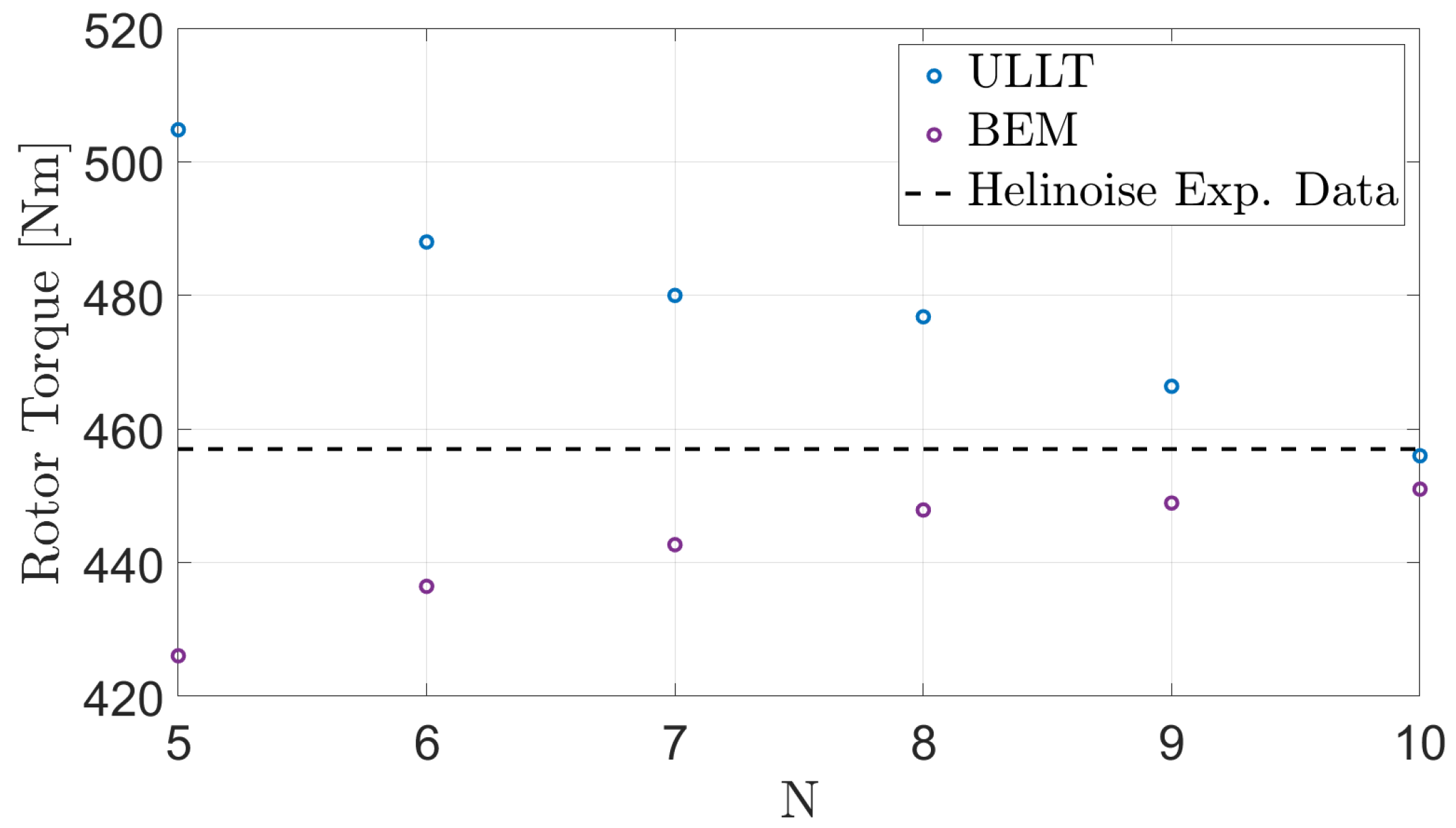
Figure 1 and Figure 2 show the convergence trends of the ULLT and BEM solvers, respectively, in terms of computed thrust and torque. They demonstrate that, for N = 10 , both solvers provide very accurate simulations as compared to the experimental data [30]. The specific relative errors with respect to the measurements are presented in Table 2 and Table 3.
Note that, for both numerical results, the effect of viscous drag on torque moment is estimated by suitably interpolating the tabulated viscous drag coefficients of the NACA 23012 airfoil given for different Reynolds and Mach numbers. The corresponding sectional viscous drag is determined at each spanwise station and integrated along the blade to yield the total torque moment contribution. Compressibility corrections were introduced to the lifting-line results for the purpose of comparison with the experimental data and BEM predictions based on a compressible-flow formulation [19].
As a result of this convergence analysis, the rest of the outcomes presented in this work are obtained by adopting N c = 60 and N s = 30 .
Figure 3 shows the time histories of ULLT and BEM thrust predictions conceived as responses to starting from rest, along with the steady thrust measured experimentally. Regarding the time-marching scheme, these results are obtained by discretizing the rotor revolution into 144 time steps (corresponding to a blade azimuth step of 2.5°). This yields converged results and is used for all the unsteady flight conditions considered in the following section.
The numerical predictions in Figure 3 present very similar trends, with practically coinciding asymptotic steady-state values, which are in excellent agreement with the experimental data (as already proven in Figure 1 and Figure 2 and Table 2 and Table 3).
These results prove the capability of the developed tool to provide accurate steady rotor load predictions.
Finally, note that the ULLT solver developed in this work is written in Fortran using an object-oriented structure, ensuring modularity and enabling straightforward parallelization. With the converged discretization described above, the code running in serial mode on an Intel Xeon CPU requires approximately 3.2 s per iteration.

3.2. Hovering Rotor with Harmonically Pitching Blades

Next, the proposed ULLT solver is validated for unsteady flow conditions. Specifically, the BO105 main rotor model is still assumed to be in hovering flight, but with blades harmonically pitching about the collective pitch angle θ 0.7 = 5 deg. The considered pitching motion has a 1 deg amplitude and 2 / r e v frequency.
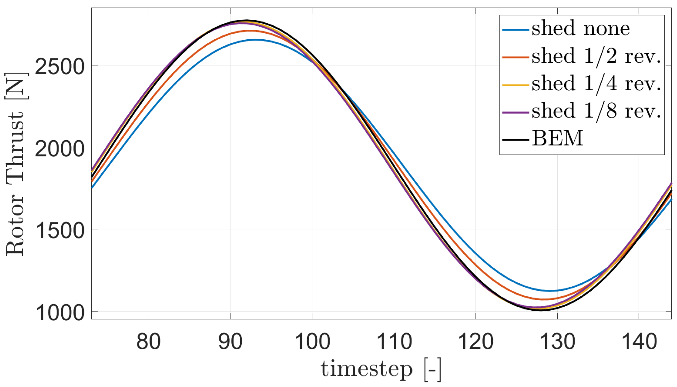
Note that a dedicated numerical investigation proved that the proposed ULLT solver yields its most accurate results when, for each blade and its associated wake, the inflow induced by shed vorticity in the first quarter-revolution of the wake is neglected (see Section 2.5). This is shown in Figure 4, which presents the thrust predicted by the ULLT solver for different extensions of the wake from which self-induced shed vorticity effects are neglected.
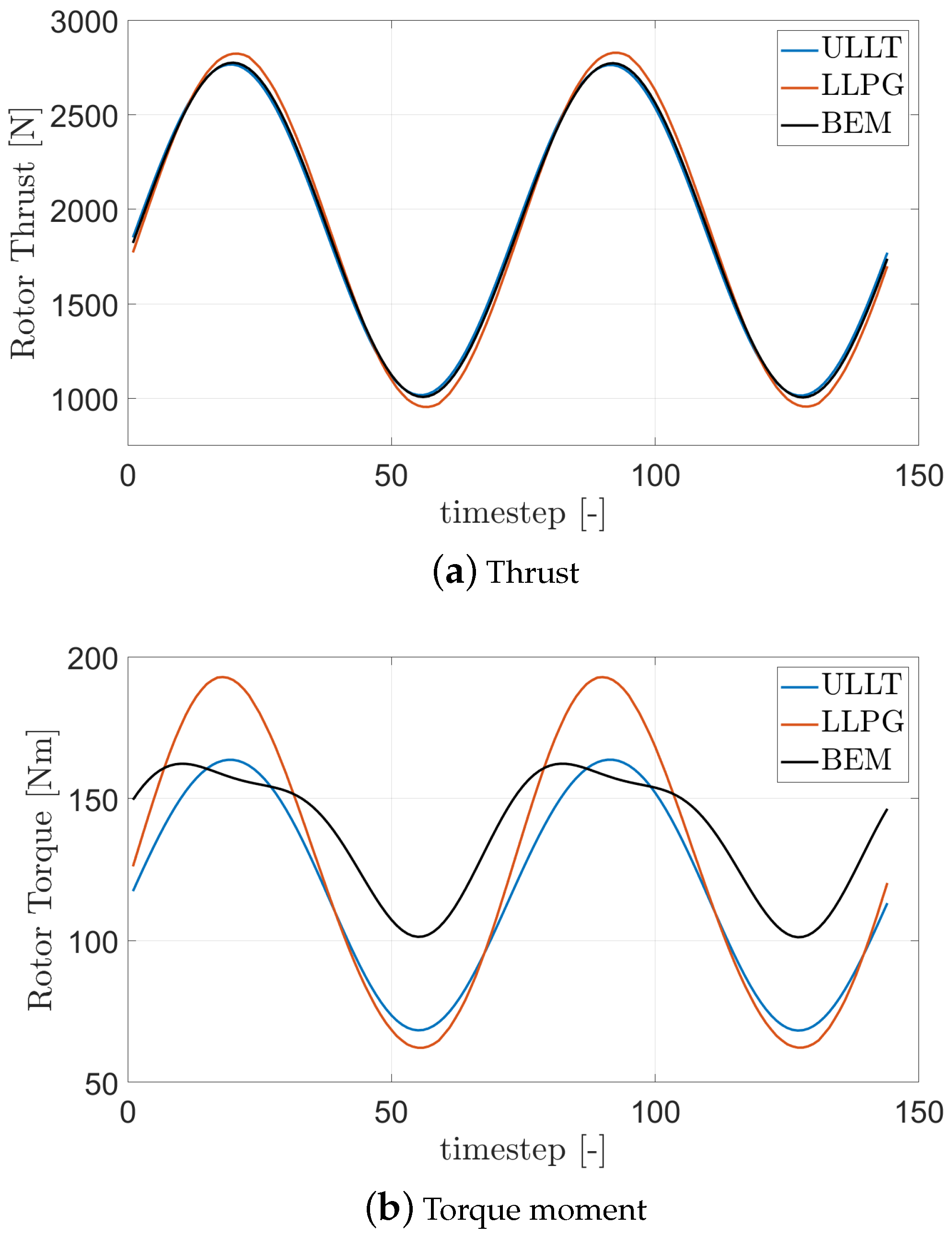
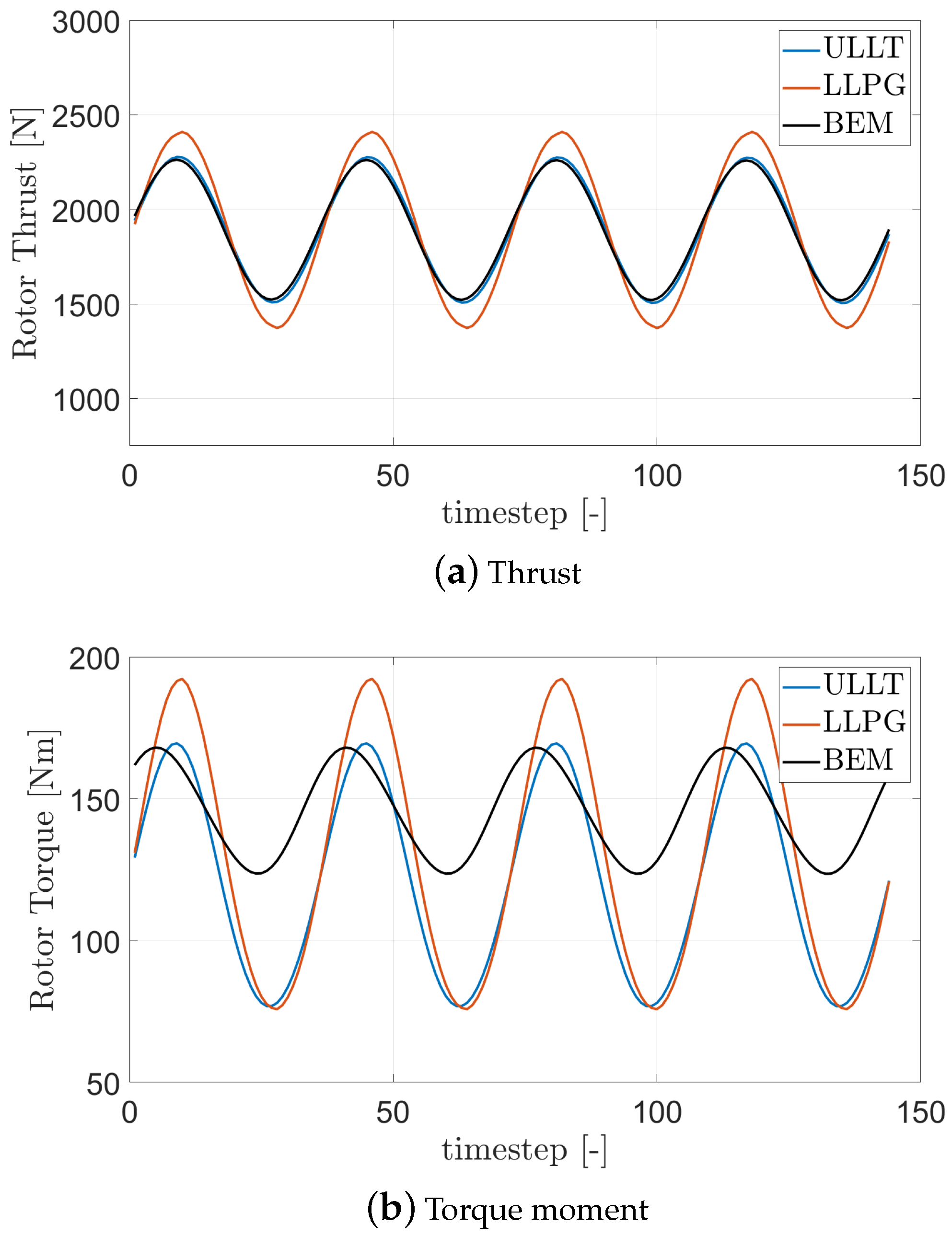
Thus, neglecting the self-induced inflow by shed vorticity in the first quarter-revolution of the wake, the regime time histories of rotor thrust and torque moment evaluated by the ULLT and BEM solvers are depicted in Figure 5 for one rotor revolution (this strategy of evaluating shed vorticity effects is adopted for all the following results). In this figure, they are also compared with the outcomes obtained by a standard Prandtl lifting line-like solver with sectional loads from Glauert’s theory and wake vorticity determined using the Kutta–Joukowski theorem for steady flows (referred to as LLPG).
Note that for the unsteady harmonic conditions, where the BEM solver provides the validation benchmark, viscous corrections have been neglected for the sake of simplicity and a clear definition of the accuracy of the potential-flow solution.
Figure 5a shows excellent agreement between the thrust predicted by the ULLT and BEM solvers. In addition, in this figure, it is possible to observe the slight enhancement of the ULLT solution adopting the unsteady Küssner–Schwarz sectional theory with respect to that given by the standard LLPG tool in terms of both the amplitude and phase of the response.
As regards Figure 5b, which shows the time history of torque, there are larger discrepancies between the ULLT and BEM predictions. This is to be expected, since the BEM solver is inherently capable of predicting induced drag, which is a phenomenon that is due to 3D effects, while lifting line-based approaches can simulate it approximately by appropriately modifying the direction of 2D sectional loads as an effect of the velocity induced by the trailed vorticity. BEM torque prediction is clearly multi-harmonic due to its intrinsic nonlinearity with respect to pressure loads (see, for instance, the well-known expression of induced drag generated by fixed wings in steady flight depending on the square of the total lift), whereas the ULLT solution is dominated by the first harmonic ( 2 / r e v ). However, compared to the LLPG solution, the ULLT result is much closer to the BEM prediction.
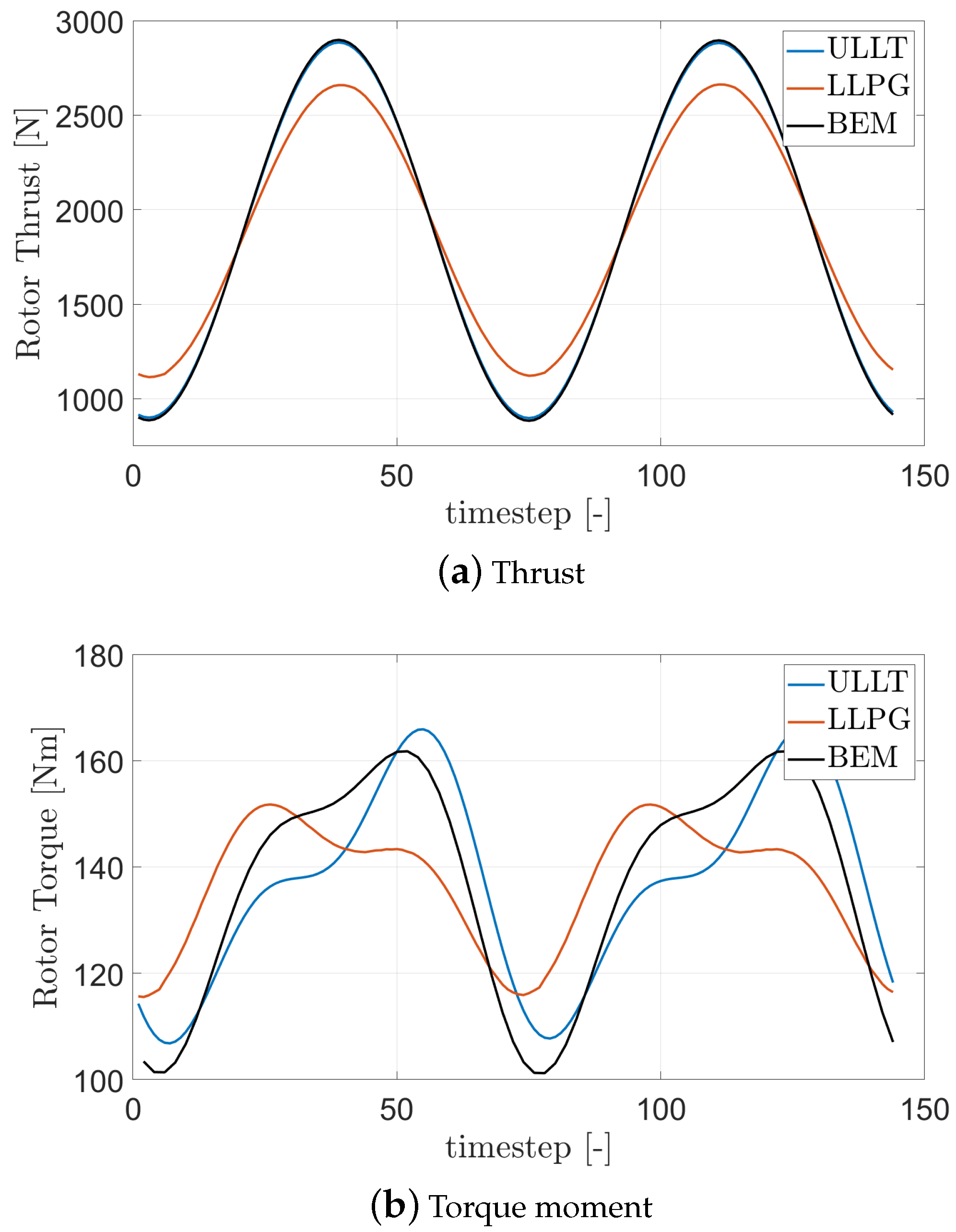
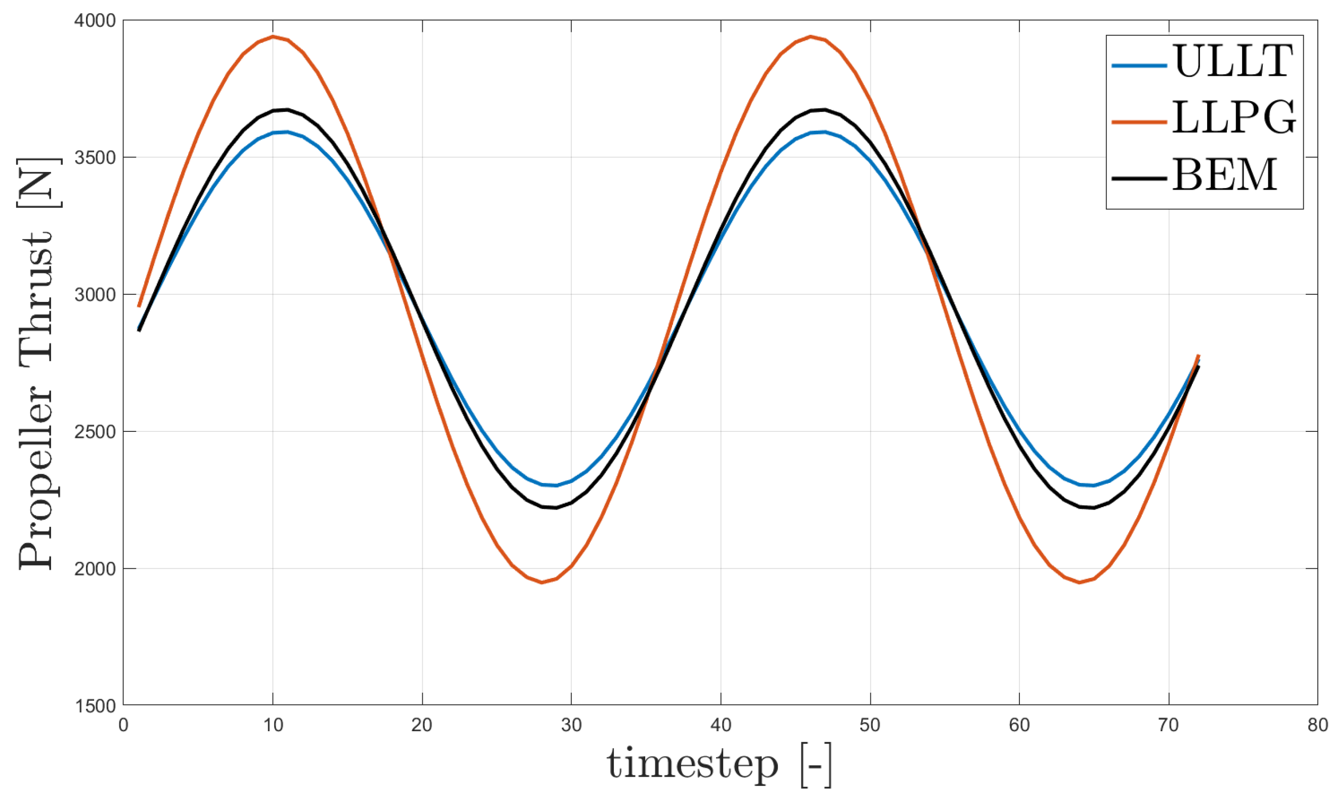
Similar results are obtained for different blade pitching frequencies. This is proven in Figure 6 and Figure 7, which show, respectively, one-revolution time histories of rotor thrust and torque moment due to 1 / r e v and 4 / r e v blade harmonic pitching (the amplitude of pitching motion is still equal to 1 deg). Indeed, in both cases, ULLT predictions of thrust are in excellent agreement with BEM results and significantly improve the LLPG prediction of thrust amplitude and phase. Instead, ULLT predictions of the torque moment present discrepancies with respect to the BEM results but are much better correlated than LLPG predictions, especially in terms of amplitude.

3.3. Hovering Rotor with Harmonically Flapping Blades

Then, the proposed ULLT solver is validated for unsteady flow conditions of the hovering BO105 main rotor model obtained from the harmonic flapping of the blades. Still assuming the collective pitch angle θ 0.7 = 5 deg, a 2 / r e v flapping motion frequency is imposed, with an amplitude such that the maximum tip displacement is 0.01 m.
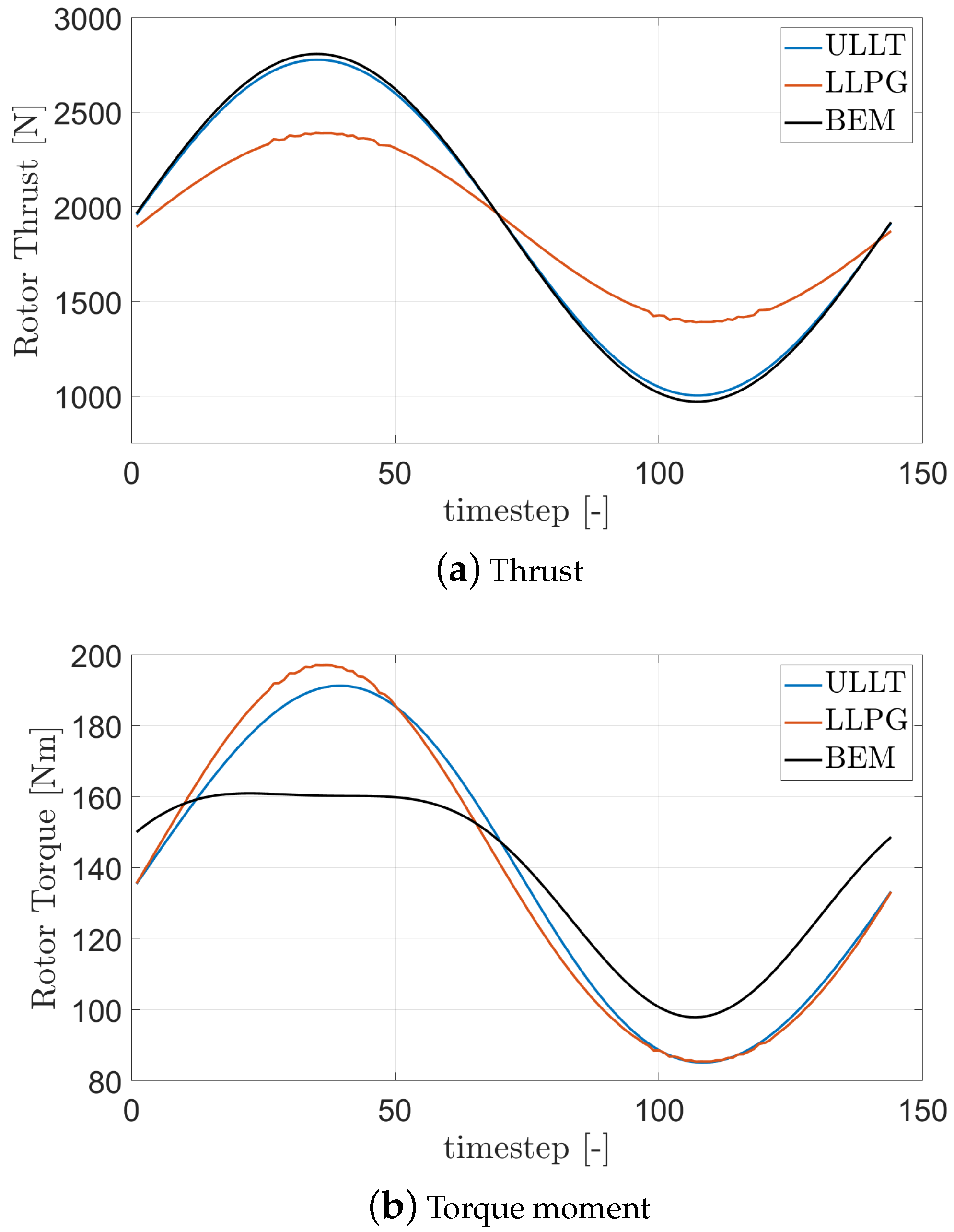
The corresponding time histories of rotor thrust and torque evaluated by the ULLT, BEM, and LLPG solvers are depicted in Figure 8 for one rotor revolution.
Regarding the evaluation of the rotor thrust, observations similar to those regarding Figure 5a can be repeated. Predictions from ULLT are in excellent agreement with BEM results and have greater accuracy than LLPG outcomes. Instead, it is interesting to notice in Figure 8b that in this case the ULLT prediction of the torque moment is much more accurate than that provided for the blade pitching cases. Indeed, a significant second-harmonic contribution also appears in the results given by the ULLT solver, which remarkably reduces the discrepancies with respect to the BEM outcomes. In addition, the prediction of the torque moment by ULLT remains much more accurate than that from the LLPG approach. The enhancement of torque prediction observed in the case of flapping blades is probably the result of the effect of trailing vortices, which is stronger than that arising in the case of pitching blades due to the corresponding larger rate of variation in radial load distribution. Indeed, the torque moment is produced by the local induced drag, which is a three-dimensional effect strongly dependent on the trailed vorticity: blade harmonic flapping produces significant harmonic variation in trailed vorticity that, coupled with local lift, generates multi-harmonic induced drag.
Similar results are obtained for lower and higher frequencies of blade flapping, which are not reported here for the sake of conciseness.
The result shown in this section and in Section 3.2 are especially meaningful, keeping in mind that lifting-line solvers are mainly developed for preliminary design applications. In this context, the improvements introduced in the proposed ULLT enable accurate frequency response predictions over a wide spectral range, thus highlighting its capability to ensure reliable rotorcraft aeroelastic analysis.

3.4. Free-Wake Analysis

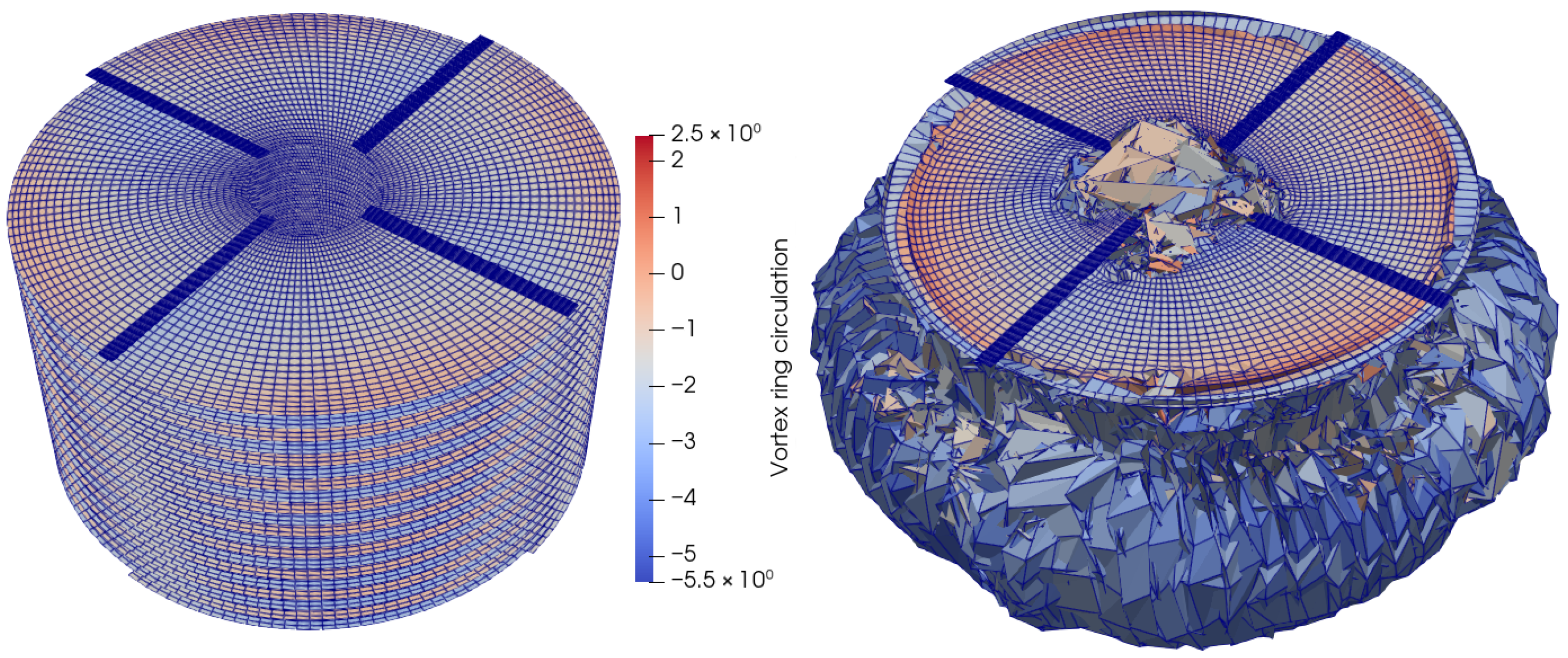
Free-wake modeling offers significant advantages over fixed-wake approaches, as it is able to capture the evolution of the rotor wake’s vortex structures. Unlike fixed-wake models, which assume a stationary wake configuration, free-wake formulations account for the convective and deformable nature of the vortical flow, revealing intricate wake topologies, inherent asymmetries, and evolving patterns that would not be included in a static model (see Figure 9).
The free-wake model provides a detailed wake characterization, which is essential for accurately capturing complex rotor–body interaction effects, such as highly nonuniform and localized load distributions, which may occur, for instance, in slow descent flight.
Figure 9 shows the shapes of the wakes considered in the free-wake and fixed-wake solution modes. The presence of secondary flow patterns in the shape of the free wake, such as the fountain effect at the center of the rotor, is evident.
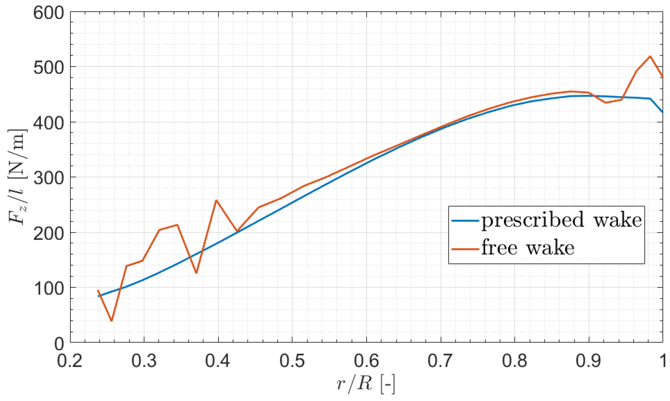
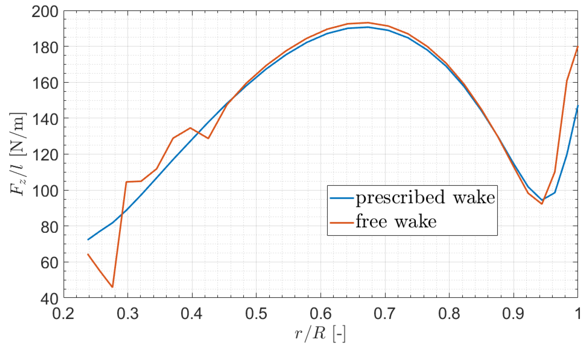
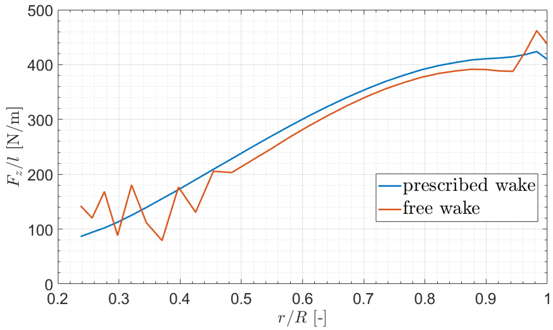
For the hovering rotor with 2 / r e v blade pitching, Figure 10, Figure 11, Figure 12 and Figure 13 show the instantaneous sectional lift distributions computed by the ULLT method through fixed-wake and free-wake solution modes at four equally spaced blade azimuth positions within one angular period of the pitching motion.
On average, the results obtained by the free-wake solution model underestimate those from the fixed-wake analysis at ψ ^ = π / 4 and ψ ^ = π , whereas they overestimate them at ψ ^ = π / 2 and ψ ^ = 3 π / 4 . As a consequence, the overall rotor loads, such as thrust and torque moment, determined by the two approaches present only marginal discrepancies (lower than 3 % ).
However, the sectional load distributions predicted by the two solution modes present significant local discrepancies. Indeed, the wake roll-up in the rotor tip region and the fountain effect in the inner rotor region (see Figure 9) produce an inflow field, which, in turn, generates local, irregular, steep change distributions of sectional loads, which do not occur in the fixed-wake analysis.
These results demonstrate that, even in the simple case of hovering flight, fixed-wake and free-wake simulations provide significantly different local predictions of the loads that affect the estimation of the vibrations and distribution of structural stresses.

3.5. Inflow Velocity Defect

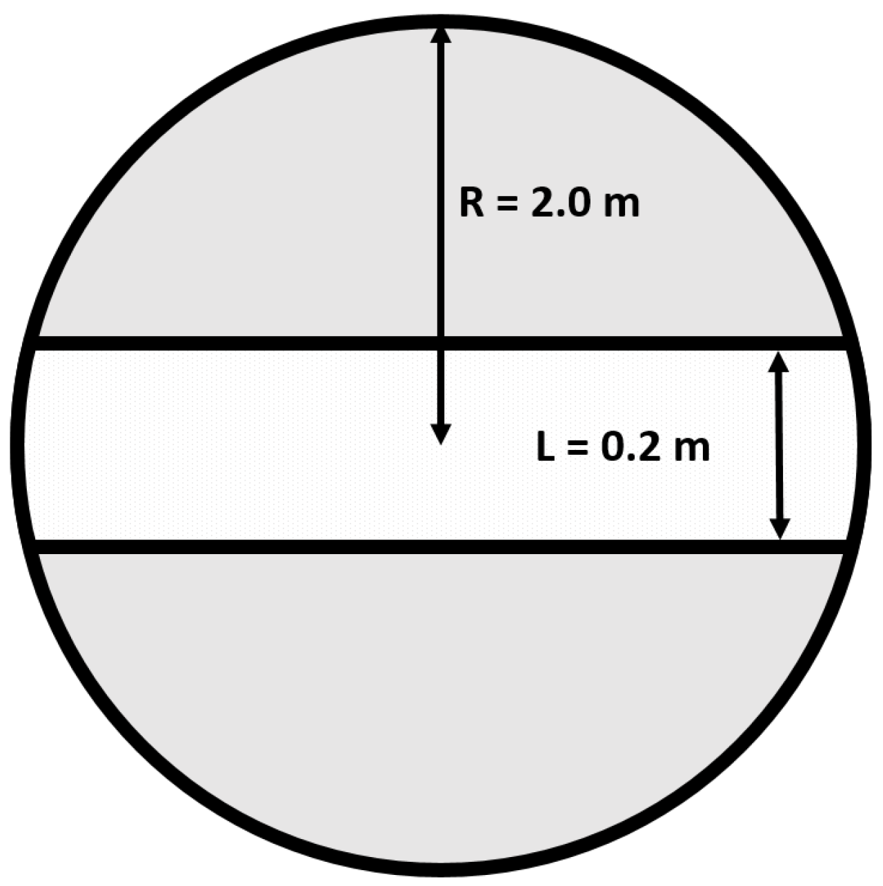
In order to validate the capability of the proposed ULLT solver to predict unsteady rotor loads corresponding to arbitrary inflow patterns, we consider the BO105 main rotor model in hovering flight, under the condition of reduced inflow within the light gray rotor disk region in Figure 14. The inflow velocity defect, which is assumed to be uniform and equal to 2 m/s here, generates a significant chordwise downwash gradient during the blade’s passage through the boundary of the defect region and correspondingly high-frequency components of rotor loads.
In particular, this inflow velocity defect serves as a simple but useful test to assess the accuracy of the proposed ULLT solution in the presence of wake impingement on a rotor blade, which may cause arbitrary chordwise distributions of downwash. Indeed, this phenomenon is quite common as it may occur in several helicopter- and propeller-driven airplane flight conditions (for instance, blade–vortex interaction in the main rotor of helicopters in descent flight or the interaction of wing wake with pushing propellers).
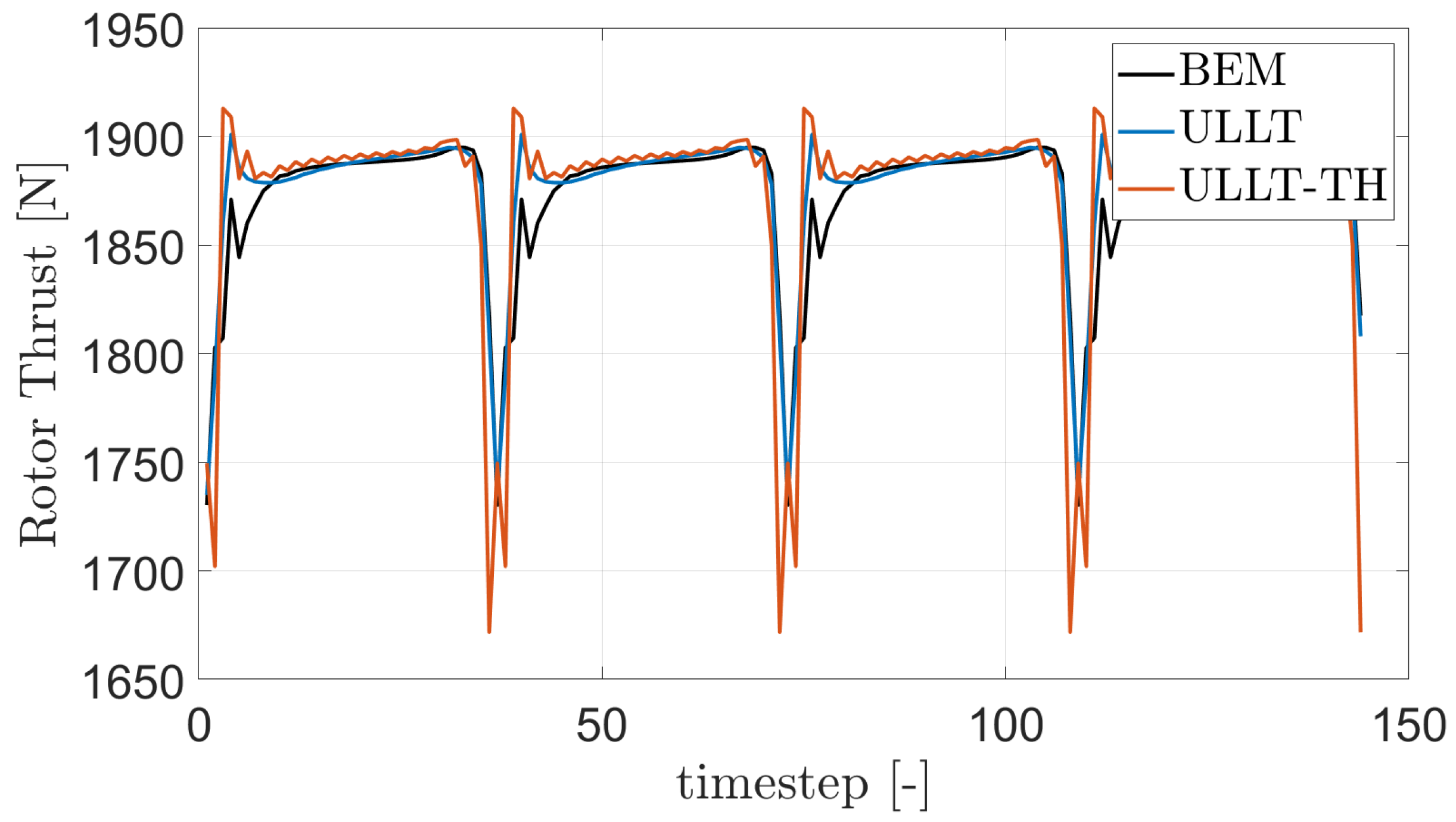
Figure 15 compares the rotor thrust in the presence of the inflow velocity defect predicted by the proposed ULLT, the BEM solver, and a lifting-line solver obtained from that described in Section 2 by replacing the Küssner–Schwarz theory with the Theodorsen theory [14] to define the sectional loads. These results prove that the proposed ULLT solver is able to provide accurate predictions of unsteady loads for arbitrary blade inflow conditions; in fact, its outcome is in good agreement with the BEM results, particularly regarding the strong thrust peak due to the blade’s passage across the boundary of the velocity defect region. The application of the Küssner–Schwarz sectional load theory is essential to account for the arbitrary distribution of downwash along the chord, unlike the widely used Theodorsen theory, which is only valid for linear distributions of downwash along the chord and significantly overpredicts thrust peaks in Figure 15.
A sectional load formulation capable of accounting for arbitrary distributions of downwash along the chord improves the accuracy of performance predictions under various conditions and provides a robust framework for optimizing blade design to mitigate adverse wake effects. This approach is ideal for applications with unconventional aeronautical configurations where complex aerodynamic interactions may occur, such as wing–proprotor eVTOL systems.

3.6. Axial Flight

Finally, the proposed ULLT solver is validated for the simulation of a propeller in axial flight.
A proprotor operating in a predominantly axial-flow regime, typical for forward flight with a high advance ratio, provides an ideal validation case for aerodynamic solvers of tilting rotors, introducing the key physical phenomena that complicate the aerodynamics of tiltrotors. In this regime, the wake behavior is characterized by significant skewing and contraction, requiring the accurate prediction of wake tip vortices. Unlike hover conditions, where free-stream velocity is negligible, axial flight challenges solvers to correctly superimpose the free-stream and induced flow.
The present investigation examines the proprotor described in Table 4. The blades are subject to harmonic pitching around the reference collective pitch value θ 0.75 = 55 deg, with amplitude equal to 1 deg and frequency equal to 2 / r e v .
Figure 16 presents a comparison among the corresponding rotor thrust predicted by the proposed ULLT, BEM, and LLPG solvers. It confirms the good accuracy of the developed solver, which provides predictions in very good agreement with BEM’s predictions for the case of the proprotor in axial flight. In contrast, the standard LLPG solution significantly overestimates the peak-to-peak thrust and exhibits a noticeable phase delay.

4. Conclusions

A novel time-domain, lifting-line formulation for the prediction of unsteady aerodynamics loads of rotors in hovering and axial flight has been introduced. The innovation is rooted in the use of the Küssner–Schwarz sectional solution model, suitably reformulated in the time domain via a rational approximation of the lift deficiency function. This approach is especially effective for computing responses to arbitrary downwash distributions (like those produced by a morphing wing or close vortex–body interactions) without requiring a complex and computationally expensive three-dimensional CFD solver. Furthermore, the formulation naturally adapts to a free-wake strategy, extending its applicability to different aerodynamic configurations. Complementing this, the full representation of load unsteadiness is achieved by incorporating the extension of the Kutta–Joukowski theorem to unsteady flows in a state-space form. The proposed formulation extends the application of the lifting-line method to arbitrarily deformable rotary wings subject to arbitrary inflow but is limited to applications in hovering and axial flight conditions, for which compressibility effects are negligible. As with any lifting-line approach, it is suitable for thin lifting surfaces and for studying problems that do not require detailed local analysis of fluid flow (in terms of either velocity or pressure). First, the proposed ULLT solver was successfully validated against experimental data regarding steady loads generated by a hovering rotor. Then, considering the same hovering rotor with harmonically pitching and flapping blades and a proprotor in axial flight with pitching blades, excellent agreement between the corresponding unsteady thrust predicted by the ULLT tool and that given by a well-validated BEM tool for an unsteady potential-flow solution was obtained. Less accurate predictions of torque moment were observed, which, however, were of significantly higher accuracy than those given by standard LLPG solutions. Quite good correlations were obtained in the case of flapping blade motion, for which significant unsteady trailed vorticity was generated. Successful validation was also achieved for the case of a hovering rotor with a significant inflow velocity defect, for which high-frequency components of loads arose. The suitability of the proposed solver for providing a free-wake simulation of rotor aerodynamics was also demonstrated, and its correlation with fixed-wake analysis proved its ability to predict detailed flow patterns and localized variations in aerodynamic loads. The good agreement of the results obtained by the proposed ULLT solver with the benchmark outcomes proves its capability to predict unsteady loads for rotors in hovering or axial flight subject to arbitrary downwash. This makes it suitable for aeroelastic applications in rotors undergoing arbitrary deformations.

Author Contributions

Conceptualization: G.F., R.G., G.B. and M.G.; methodology: G.F., R.G., G.B. and M.G.; software: G.F., R.G. and G.B.; validation, G.F. and R.G.; writing—original draft preparation: G.F. and R.G.; writing—review and editing: G.F., R.G., G.B. and M.G. All authors have read and agreed to the published version of the manuscript.

Funding

This research received no external funding.

Data Availability Statement

The original contributions presented in the study are included in the paper. Further enquiries can be directed to the corresponding author.

Conflicts of Interest

The authors declare no conflicts of interest.

Nomenclature

Symbols
A , B , C , D matrices of the non-circulatory part of the generalized aerodynamic loads
a n Küssner-Schwarz pressure coefficients
b , c semi-chord and chord lengths, m
C ( k ) Theodorsen (lift deficiency) function
c n coefficients of rational approximation
F z lift force, N
f m , f generalized aerodynamic loads and relative vector
g , h , l vectors of circulatory part of generalized aerodynamic loads
H ( k ) reciprocal of the Kutta–Joukowski frequency response function
kreduced frequency
Ldefect region length, m
Mnumber of modes
Nnumber of Küssner-Schwarz coefficients
P n Küssner-Schwarz downwash coefficients
p n poles of the rational approximation
Qrotor torque, Nm
q m , q Lagrangian coordinates and relative vector
Rrotor radius, m
radditional aerodynamic state, or radial position, m
Trotor thrust, N
t vector of the non-circulatory part of the generalized aerodynamic loads due to the induced velocity
tdimensional time, s
Vunperturbed flow velocity, m/s
vdownwash distribution, m/s
v i induced velocity, m/s
wvertical displacement, m
z n zeroes of the rational approximation
Γ bound circulation, m2/s
Δ p pressure jump distribution, N/m2
θ polar nondimensional chordwise coordinate
θ t w linear twist distribution, deg/m
ξ nondimensional chordwise coordinate
ρ air density, kg/m3
τ nondimensional time
ψ m set of shape functions
ψ ^ rotor azimuthal position, rad
Ω rotor angular speed, rad/s
ω angular frequency, rad/s
Apices
ccirculatory part
Hrelative to the rational approximation of H ( k )
n c non-circulatory part
Abbreviations
BEMBoundary Element Method
CFDComputational Fluid Dynamics
LLPGLifting-Line Theory Prandtl-Glauert
LLTLifting-Line Theory
ULLTUnsteady Lifting-Line Theory
ULLT-THUnsteady Lifting-Line Theory - Theodorsen

References

  1. Prandtl, L. Applications of Modern Hydrodynamics to Aeronautics; NACA TR-116. 1923. Available online: https://ntrs.nasa.gov/api/citations/19930091180/downloads/19930091180.pdf (accessed on 1 October 2025).
  2. Weissinger, J. The Lift Distribution of Swept-Back Wings; NACA TM-1120. 1947. Available online: https://ntrs.nasa.gov/api/citations/20030064148/downloads/20030064148.pdf (accessed on 1 October 2025).
  3. Prössdorf, S.; Tordella, D. On an extension of Prandti’s lifting line theory to curved wings. IMPACT Comput. Sci. Eng. 1991, 3, 192–212. [Google Scholar] [CrossRef]
  4. Phillips, W.F.; Snyder, D.O. Modern Adaptation of Prandtl’s Classic Lifting-Line Theory. J. Aircr. 2000, 37, 662–670. [Google Scholar] [CrossRef]
  5. Sclavounos, P.D. An unsteady lifting-line theory. J. Eng. Math. 1987, 21, 201–226. [Google Scholar] [CrossRef]
  6. Chiocchia, G.; Tordella, D.; Prössdorf, S. The Lifting Line Equation for a Curved Wing in Oscillatory Motion. ZAMM—J. Appl. Math. Mech./Z. Angew. Math. Mech. 1997, 77, 295–315. [Google Scholar] [CrossRef]
  7. Drela, M. Integrated simulation model for preliminary aerodynamic, structural, and control-law design of aircraft. In Proceedings of the 40th Structures, Structural Dynamics, and Materials Conference and Exhibit, St. Louis, MO, USA, 12–15 April 1999; p. 1394. [Google Scholar] [CrossRef]
  8. Sugar-Gabor, O. A general numerical unsteady non-linear lifting line model for engineering aerodynamics studies. Aeronaut. J. 2018, 122, 1199–1228. [Google Scholar] [CrossRef]
  9. Boutet, J.; Dimitriadis, G. Unsteady Lifting Line Theory Using the Wagner Function for the Aerodynamic and Aeroelastic Modeling of 3D Wings. Aerospace 2018, 5, 92. [Google Scholar] [CrossRef]
  10. Izraelevitz, J.S.; Zhu, Q.; Triantafyllou, M.S. State-Space Adaptation of Unsteady Lifting Line Theory: Twisting/Flapping Wings of Finite Span. AIAA J. 2017, 55, 1279–1294. [Google Scholar] [CrossRef]
  11. Bird, H.J.A.; Ramesh, K. Unsteady Lifting-Line Theory and the Influence of Wake Vorticity on Aerodynamic Loads. Theor. Comput. Fluid Dyn. 2021, 35, 609–631. [Google Scholar] [CrossRef]
  12. Yannic Beyer, Y.; Ullah, J.; Steen, M.; Hecker, P. Unsteady Nonlinear Lifting Line Model for Active Gust Load Alleviation of Airplanes. CEAS Aeronaut. J. 2024, 15, 917–932. [Google Scholar] [CrossRef]
  13. Goates, C.D.; Hunsaker, D.F. Modern Implementation and Evaluation of Lifting-Line Theory for Complex Geometries. J. Aircr. 2023, 60, 490–508. [Google Scholar] [CrossRef]
  14. Theodorsen, T. General Theory of Aerodynamic Instability and the Mechanism of Flutter; NACA TR-496. 1935. Available online: https://ntrs.nasa.gov/api/citations/19800006788/downloads/19800006788.pdf (accessed on 1 October 2025).
  15. Wagner, H. Über die Entstehung des dynamischen Auftriebes von Tragflügeln. ZAMM—J. Appl. Math. Mech./Z. Angew. Math. Mech. 1925, 5, 17–35. [Google Scholar] [CrossRef]
  16. Giansante, R.; Bernardini, G.; Gennaretti, M. Unsteady Lifting-Line Theory for Camber Morphing Wings State-Space Aeroelastic Modeling. AIAA J. 2024, 62, 4654–4664. [Google Scholar] [CrossRef]
  17. Frassoldati, G.; Giansante, R.; Bernardini, G.; Gennaretti, M. Unsteady Lifting-Line Free-Wake Aerodynamic Modeling for Morphing Wings. Aerospace 2024, 11, 745. [Google Scholar] [CrossRef]
  18. Gennaretti, M.; Giansante, R. Kutta–Joukowski Theorem for Unsteady Linear Aerodynamics. AIAA J. 2022, 60, 5779–5790. [Google Scholar] [CrossRef]
  19. Gennaretti, M.; Luceri, L.; Morino, L. A Unified Boundary Integral Methodology for Aerodynamics and Aeroacoustics of Rotors. J. Sound Vib. 1997, 200, 467–489. [Google Scholar] [CrossRef]
  20. Sears, W.R. Some Aspects of Non-Stationary Airfoil Theory and Its Practical Application. J. Aeronaut. Sci. 1941, 8, 104–108. [Google Scholar] [CrossRef]
  21. Giesing, J.; Rodden, W.; Stahl, B. Sears Function and Lifting Surface Theory for Harmonic Gust Fields. J. Aircr. 1970, 7, 252–255. [Google Scholar] [CrossRef]
  22. Küssner, H.G. Summary Report on the Nonstationary Lift of Wings. Luftfahrtforschung 1936, 13, 410–424. (In German) [Google Scholar]
  23. Küssner, H.; Schwarz, I. The Oscillating Wing with Aerodynamically Balanced Elevator; NACA TR-991. 1941. Available online: https://ntrs.nasa.gov/api/citations/19930094383/downloads/19930094383.pdf (accessed on 1 October 2025).
  24. Fung, Y. An Introduction to the Theory of Aeroelasticity; Dover Publications, Inc.: New York, NY, USA, 1993. [Google Scholar]
  25. Venkatesan, C.; Friedmann, P.P. New Approach to Finite-State Modeling of Unsteady Aerodynamics. AIAA J. 1986, 24, 1889–1897. [Google Scholar] [CrossRef]
  26. Katz, J.; Plotkin, A. Low-Speed Aerodynamics, 2nd ed.; Cambridge Aerospace Series; Cambridge University Press: Cambridge, UK, 2001. [Google Scholar] [CrossRef]
  27. Jones, R. Operational Treatment of the Nonuniform-Lift Theory to Airplane Dynamics; NACA TN-667. 1938. Available online: https://ntrs.nasa.gov/api/citations/19930081472/downloads/19930081472.pdf (accessed on 1 October 2025).
  28. Peters, D.A. Two-Dimensional Incompressible Unsteady Airfoil Theory—An Overview. J. Fluids Struct. 2008, 24, 295–312. [Google Scholar] [CrossRef]
  29. Gennaretti, M. Fundamentals of Aeroelasticity; Springer Nature: Cham, Switzerland, 2024. [Google Scholar] [CrossRef]
  30. Heller, H.; Splettstoesser, W.; Kloeppel, V.; Cenedese, F. HELINOISE—The European Community Rotor Acoustics Research Program. AIAA J. 1993. [Google Scholar] [CrossRef]
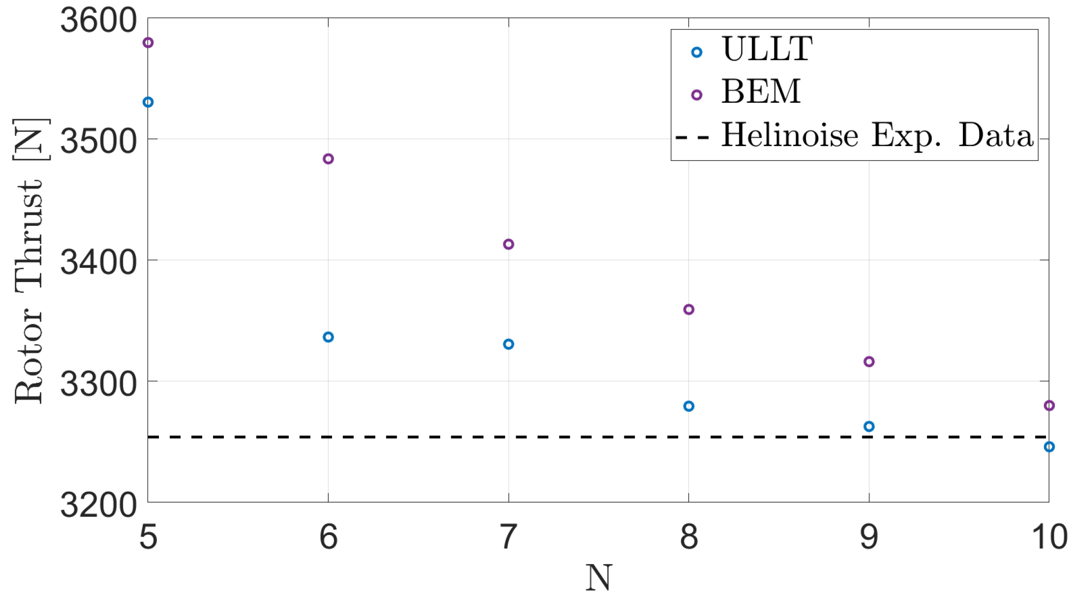
Figure 1. Thrust convergence trend for hovering rotor.
Applsci 15 12332 g001
Figure 2. Torque convergence trend for hovering rotor.
Applsci 15 12332 g002
Figure 3. Experimental and predicted thrust for hovering rotor.
Applsci 15 12332 g003
Figure 4. Shed vorticity contribution effects on ULLT thrust predictions.
Applsci 15 12332 g004
Figure 5. Thrust and torque moment due to 2 / r e v blade harmonic pitching.
Applsci 15 12332 g005
Figure 6. Thrust and torque moment due to 1 / r e v blade harmonic pitching.
Applsci 15 12332 g006
Figure 7. Thrust and torque moment due to 4 / r e v blade harmonic pitching.
Applsci 15 12332 g007
Figure 8. Thrust and torque moment due to 2 / r e v blade harmonic flapping.
Applsci 15 12332 g008
Figure 9. Prescribed-wake and free-wake configurations for hovering rotor with 2 / r e v harmonic pitching motion of blades.
Applsci 15 12332 g009
Figure 10. Sectional lift distribution at ψ ^ = π / 4 .
Applsci 15 12332 g010
Figure 11. Sectional lift distribution at ψ ^ = π / 2 .
Applsci 15 12332 g011
Figure 12. Sectional lift distribution at ψ ^ = 3 π / 4 .
Applsci 15 12332 g012
Figure 13. Sectional lift distribution at ψ ^ = π .
Applsci 15 12332 g013
Figure 14. Region of inflow velocity defect over rotor disk (light gray region).
Applsci 15 12332 g014
Figure 15. Time history of thrust in the presence of inflow velocity defect.
Applsci 15 12332 g015
Figure 16. Proprotor thrust due to 2 / r e v blade harmonic pitching.
Applsci 15 12332 g016
Table 1. HELINOISE rotor characteristics.
Radius (R)2.0 m
Chord0.121 m
Twist Ratio ( θ t w )–4.0 deg/m
Null Twist@0.70R
Root Cutout0.22R
Section AirfoilNACA23012
Rotational Speed1041 RPM
Reference Collective Pitch ( θ 0.7 )5.0 deg
Table 2. Relative error of computed thrust.
NBEMULLT
510.0%8.5%
67.1%2.5%
74.9%2.3%
83.2%1.0%
91.9%0.3%
100.8%0.2%
Table 3. Relative error of computed torque.
NBEMULLT
56.8%10.5%
64.5%6.7%
73.1%5.0%
82.0%4.3%
91.8%2.1%
101.3%0.5%
Table 4. Proprotor characteristics.
Radius (R)3.6 m
Chord0.250 m
Twist Ratio ( θ t w )–7.64 deg/m
Null Twist@0.75R
Root Cutout0.25R
Section AirfoilNACA0012
Rotational Speed300 RPM
Cruise Speed200 keas
Reference Collective Pitch ( θ 0.75 )55 deg
Disclaimer/Publisher’s Note: The statements, opinions and data contained in all publications are solely those of the individual author(s) and contributor(s) and not of MDPI and/or the editor(s). MDPI and/or the editor(s) disclaim responsibility for any injury to people or property resulting from any ideas, methods, instructions or products referred to in the content.