Article

Stability Assessment of Unilateral External Fixator Configurations for Open Tibial Fractures: An Experimental Study

Department of Mechanical Design, Faculty of Mechanical Engineering, University of Sarajevo, 71000 Sarajevo, Bosnia and Herzegovina
*
Author to whom correspondence should be addressed.
Appl. Sci. 2025, 15(22), 12327; https://doi.org/10.3390/app152212327
Submission received: 26 October 2025 / Revised: 17 November 2025 / Accepted: 18 November 2025 / Published: 20 November 2025

Abstract

The primary objective of external fixation is to stabilize bone fractures, with the mechanical characteristics of the fixation system playing a critical role in shaping the biomechanical environment of the fracture and, consequently, the healing process. This study presents an experimental investigation of the stability of eight unilateral external fixation configurations applied to an open tibial fracture. The stiffness of each configuration was evaluated under axial compression, anterior–posterior (AP) bending, medial–lateral (ML) bending, and torsional loading. In addition, the effects of structural parameters—such as the number of half-pins, planarity of the configuration, and interfragmentary distance—on fixator stiffness and generated stresses were examined. The results revealed a linear relationship between applied load and both bone segment displacement and principal stresses. Biomechanical tests demonstrated that biplanar configurations provide sufficient stability for open tibial fractures, while simultaneously offering an optimal structural design for the fixation system. Moreover, the number of half-pins was identified as a statistically significant factor influencing configuration stiffness under axial loading and torsion, with biplanar configurations proving particularly effective in torsional scenarios. However, in AP and ML bending tests, neither configuration type nor any individual parameter produced statistically significant differences in bending stiffness. Interestingly, interfragmentary distance did not exert a statistically significant effect on configuration stiffness under any loading condition. Furthermore, neither configuration type nor the analyzed parameters had a notable influence on the principal stresses measured at the control points.

1. Introduction

Bone tissue discontinuities, commonly referred to as fractures, represent one of the most common forms of trauma. These injuries typically result either from high-energy impacts and mechanical overloading or from structurally weakened bones due to osteoporosis or other pathological conditions affecting bone integrity. Among the key techniques for managing such injuries is external fixation, which provides not only biomechanical stability but also facilitates subsequent medical interventions without the need for additional invasive surgical procedures. Nevertheless, external fixators must meet stringent biomechanical requirements in order to effectively support fracture healing while minimizing the risk of complications [1,2].
External fixation is a therapeutic orthopedic-traumatological method of fracture immobilization involving the insertion of pins or wires into or through the bone and their connection to an external frame. The fundamental concept of this technique has remained unchanged since its inception, while the materials, pins, and fixator designs have undergone significant evolution. External fixation is considered a relatively safe, minimally invasive procedure that enables easy monitoring of the fracture site and associated soft tissue injuries, while ensuring sufficient fracture stability without the presence of fixator components at the fracture line. The success of external fixation depends heavily on a thorough understanding of fracture mechanics, fixation principles, and the structural integrity of the bone-fixator system [3,4].
Numerous studies have identified external fixation as the treatment of choice particularly for complex open fractures of the tibia and femur, due to its effectiveness and low complication rates. It is also used for simpler oblique or transverse fractures [5,6,7]. In clinical practice, the selection of a specific fixator type is often based on the surgeon’s personal preferences and experience [2,8,9].
The strain theory proposed by Perren defines the limits of mechanical strain for tissue differentiation and has been fundamental in fracture management. It emphasizes that both the type and magnitude of mechanical stimuli are critical factors determining the nature of tissue formation within the fracture callus. The degree of fragment immobilization and anatomical repositioning governs the type of tissue that can develop and persist between fracture ends, thereby dictating the type of bone healing: primary, secondary, or non-union. Optimal functional recovery of fractured bones relies on effective immobilization and accurate anatomical reduction of bone segments, which are achieved through proper use of the external fixator. Additionally, early weight-bearing on the injured limb is desirable to accelerate the healing process and minimize the duration of fixation. This approach helps reduce the risk of disuse-related complications such as osteoporosis and muscle atrophy, while promoting the restoration of the bone’s biomechanical properties [10,11,12].
Various types of external fixators have been developed for different clinical applications. For instance, simple fixators offer sufficient stability, modular designs enable rapid and convenient application, and circular fixators with fine wires allow for multiplanar control of small fragments. Moreover, adjustable joints within the system enable controlled dynamization, facilitating targeted compressive forces at the fracture site or between bone fragments [13]. In general, external fixators are expected to meet the following design and clinical criteria: (1) low complication rates, (2) adequate stability for fracture and soft tissue healing, (3) configurational adaptability, and (4) ease of application [14].
The stiffness of fracture stabilization using external fixators is influenced by multiple factors, including the type of fixator, its geometric positioning relative to the bone, and specific application techniques. Both insufficient and excessive stiffness can hinder the healing process. Inadequate stability delays tissue repair, while overly rigid constructs can also impair callus formation. Notably, the stiffness and overall stability of the fixator not only affect the magnitude of interfragmentary motion and alignment at the fracture site but are also directly linked to complications such as screw or pin loosening [15,16,17,18].
In light of modern theories regarding interfragmentary compression during bone healing, contemporary external fixation devices are designed to allow controlled micromotion at the fracture site to stimulate callus formation. Stable, dynamic, and flexible external fixator constructs are capable of maintaining fracture reduction, angular and longitudinal alignment of bone fragments, while simultaneously promoting biologically favorable micromotion [19].
Biomechanical studies of external fixators place significant emphasis on evaluating the influence of design parameters on fixator stability. Experimental investigations are commonly conducted to assess the effects of pin and wire placement and count on the stiffness of hybrid fixators under axial loading and bending in two planes [20]. Similarly, the influence of pin count, connecting rods, and clamp positioning on the stiffness of the Hoffmann unilateral, uniplanar fixator has been examined. These studies typically test fixators under axial compression, anteroposterior (AP) and mediolateral (ML) bending, as well as torsional loading. Deformation of the fixator frame has often been observed at the universal ball joints. Based on experimental findings, it was recommended that the torque applied to ball joint clamps should not be less than 11 Nm to ensure adequate frame stability [21].
Similar experimental methodologies have been applied to investigate the biomechanical performance of internal spinal fixators and to determine the effects of specific structural parameters under various loading conditions [22]. Moroz et al. [23] compared the stability of two external fixator types: the original Hoffmann fixator and the AO tubular fixator, across four configurations. The study included unilateral constructs with one or two connecting rods, dual unilateral autonomous fixators with half-pins inserted at 45°, and a delta-frame configuration in which rods were connected using two transverse bars. Based on biomechanical evaluations, the authors recommended the use of delta or dual-frame configurations for managing high-load scenarios and comminuted fractures with significant bone loss.
Remiger [24] conducted an experimental study comparing the mechanical properties of a pinless external fixator applied to the tibia with AO tubular and Ultra-x fixators. The study concluded that AO tubular fixators demonstrated superior stability under all tested loading conditions. The tests were performed on cadaveric tibiae, and it was determined that axial stiffness was the primary weakness of the pinless fixator, regardless of clamp material, size, or geometry. The pinless fixator exhibited only 61% of the bending stiffness of the comparable AO tubular fixator.
Additional studies have tested external fixators under axial compression to determine stiffness across three identical configurations with varying K-wire diameters. It was found that 3 mm K-wires provided approximately 41% greater stiffness under axial compression compared to 2 mm wires [25].
Experimental and numerical methods have also been employed to analyze the Orthofix Limb Reconstruction System, using a simplified tibia model. The system was evaluated for varying pin numbers and distances between the fixator frame and the bone. Results quantified the load-sharing characteristics of the fracture and demonstrated the dependence of load transfer on the frame-to-bone distance [26].
Simpson et al. [27] investigated and determined the maximum axial forces occurring between bone segments at the fracture site across different patients and fracture pathologies. Using load cells, they monitored axial forces during the healing of both open and closed tibial fractures. Continuous monitoring of fixator loading enables the estimation of fracture stiffness and provides insight into the progression of healing [28]. Furthermore, simulations of the healing process are being developed and validated through in vivo experiments involving continuous implant load monitoring, which in turn allows assessment of the healing process itself [29].
Numerous multidisciplinary research teams are developing their own fixator designs. For example, a monolateral external fixation system for limb lengthening was created with a simpler assembly process compared to commercial systems. The system, composed of clamps, screws, and rails, was tested in accordance with ASTM F1541, and demonstrated stiffness values comparable to commercial devices [30].
Ongoing research focuses on the redesign of existing fixators to improve their biomechanical performance. In study [31], torsional, AP, and ML bending stiffness of the Hoffmann 3 external fixator system were measured and compared with the Hoffmann II MRI fixator, which is widely accepted. Findings indicated that the improved Hoffmann 3 design provided superior stiffness.
Similarly, biomechanical analysis was performed on a prototype unilateral external fixator for tibial fractures, based on the commercial Orthofix system. Both static and dynamic tests were carried out to compare the mechanical characteristics of the prototype to the Orthofix standard. During static testing under axial loading and bending, displacements were monitored using the Aramis optical measurement system. The prototype demonstrated higher stiffness under bending, while the Orthofix fixator exhibited greater stiffness in axial loading. No significant differences were observed during cyclic loading tests [32].
In addition to traditional metallic materials, an increasing number of experimental and numerical studies have investigated the use of composite materials in external fixation devices, owing to their favorable properties. One such study examined an external fixator in which the clamp (socket) was manufactured from carbon fiber/polyphenylene sulfide (C/PPS) pellets, while the rod was fabricated from carbon fiber/epoxy (C/epoxy). Both static and fatigue tests were conducted on two fixator configurations to assess their mechanical performance [33].
As part of a pilot study, a unilateral uniplanar external fixator was tested on a simplified transverse diaphyseal fracture, and subsequently, computational models were developed to assess the stability of the system. These models were used to define an optimal configuration aimed at developing a surgical decision-support tool that assists surgeons in planning fixator configurations based on fracture type and anatomical location. Model validation was carried out through experimental testing in accordance with ASTM F1541 [34].
In another study [35], the authors observed an increase in deformation in the bone model and a decrease in deformation within fixator components during callus maturation under axial loading, bending, and torsional moments. The research focused on analyzing the load transfer mechanisms between the fixator and bone model by measuring strain within the bone-fixator system throughout four healing phases, using both experimental and finite element analysis (FEA) methods. Twenty strain gauges were applied to the fixator and bone model to quantify deformations during the healing process.
In a related investigation [36], a custom-developed electromechanical system was used to monitor the stiffness of an osteotomy during the application of a unilateral fixator. Similarly, real-time monitoring of fracture healing was performed to assess the biomechanical performance of a unilateral external fixator applied to a transverse osteotomy. The study was conducted on six ovine models, with strain gauges attached to the outer surface of the fixator to monitor deformations throughout the healing period [37].
In this study, we conducted an experimental investigation of the stability of eight configurations of the Sarafix unilateral external fixation system for open tibial fractures, analyzing their stiffness and principal stresses at the control points of the fixator frame. Stability tests were performed under axial compression, anteroposterior (AP) bending, mediolateral (ML) bending, and torsion. The effects of the examined factors—the number of half-pins (ranging from four to ten), configuration planarity (uniplanar or biplanar), and interfragmentary gap (20 or 50 mm)—on configuration stiffness and induced stresses were systematically evaluated.

Sarafix External Fixation System

The Sarafix external fixation system is a unilateral, biplanar modular fixator that utilizes half-pins (Schanz screws). The idea for developing the external fixator emerged in May 1992, driven by the insufficient availability of existing fixators in besieged Sarajevo. Shortly thereafter, the first prototype, referred to as the Sarajevo War Fixator (Sarafix), was developed by a multidisciplinary team of orthopedic surgeons and mechanical engineers.
One of the primary design requirements was the ability to apply the fixator rapidly and easily to all segments of the musculoskeletal system. The system was also designed to enable postoperative fragment repositioning without the need to remove the fixator rod or reposition the half-pins.
During the war in Bosnia and Herzegovina, the Sarafix system was extensively used in the treatment of complex gunshot- and blast-related fractures of long bones, contributing to limb salvage in a large number of patients [38]. In peacetime trauma care, it has been applied in the management of accidental injuries, including those caused by traffic accidents and industrial trauma. The Sarafix fixator has been recognized internationally, receiving gold medals at the Brussels Eureka (1995) and the Geneva International Exhibition of Inventions (1996).
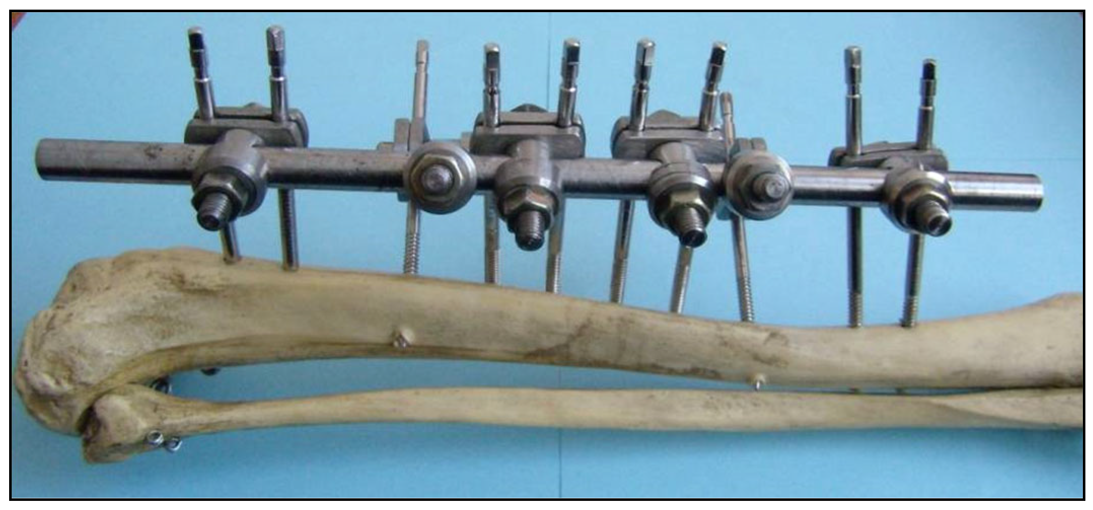
Structurally, the system consists of four main components (Figure 1): the rod (1), clamp holder (2), clamp (3), and half-pin (4).
The conditions under which the Sarafix fixator was developed significantly limited the choice of construction materials. Since materials used in external fixation devices must exhibit not only adequate mechanical strength but also high resistance to chemical influences, stainless steel was selected as the most suitable option, owing to its availability and performance.
Accordingly, the rod, clamp holder, and clamp of the Sarafix system were manufactured from martensitic stainless steel, grade X30Cr13, in compliance with the EN 10088 standard [39]. The fixator employs standard 5 mm Schanz screws (half-pins) made of austenitic stainless steel, grade X2CrNiMo18-14-3, also according to EN 10088.
The rod is produced in two lengths (320 mm and 450 mm). The design of the clamp holder allows for multiplanar placement of half-pins using a single rod. The clamp can be attached either directly to the rod or via the clamp holder. Additionally, the use of a dual-pin clamp reduces the number of individual components required.
The design of the Sarafix system provides rotational and axial mobility between its components: the clamp holder (2) relative to the rod (1), the clamp (3) relative to the clamp holder, and the half-pin (4) relative to the clamp (Figure 2).
Owing to the mobility of its components, the design of the Sarafix system allows independent placement of each half-pin without the need for specialized instruments. The insertion site of each pin is determined not by the geometry of the fixator, but by the condition of the skin and surrounding soft tissues.
Accurate fracture reduction can be achieved without reliance on X-ray, ultrasound, or other imaging modalities. This feature enables effective fracture management not only in well-equipped surgical centers, but also in resource-limited orthopedic units or field hospitals, provided that the surgeon is trained in the use of the device [38].
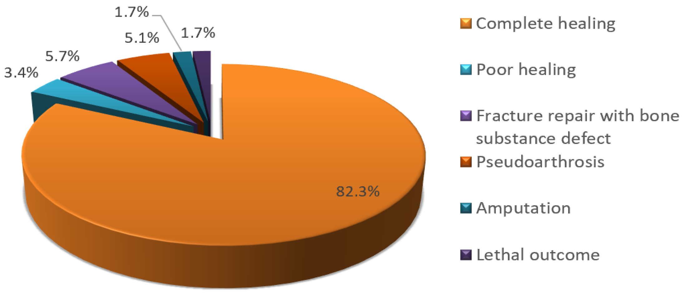
Clinical outcomes with the Sarafix fixator have been exceptionally positive. Results from a study conducted on a sample of 175 applied fixators for extensive limb injuries at the State Hospital Sarajevo, during the war period from May 1992 to May 1995, showed the following:
The success rate of treating grade II and III open fractures using the Sarafix fixator was 82.3% (Figure 3).
Sarafix was used as the definitive immobilization method in 88.3% of cases.
The average fixation duration for the tibia was seven months.
The most frequent anatomical sites for fixator application were: tibia (34.8%), femur (26.3%), humerus (17.2%), ulna (11.4%), radius (10.3%).
Pin-site infections were observed in 6% of patients during treatment.
The most common injury mechanism was open fractures with extensive soft tissue damage caused by shrapnel in 68% of cases; the remaining were gunshot-related fractures.
Despite extensive limb injuries, a high percentage of fractures healed successfully, with good functional outcomes. A distinct subgroup consisted of healed fractures with segmental bone defects, in which limb function was preserved even in cases of severe, high-energy war-related injuries, most frequently caused by grenade shrapnel. Fatal outcomes were primarily associated with severe polytrauma involving other organ systems, where non-orthopedic injuries represented the main cause of death [38,40].

2. Materials and Methods

2.1. Test Configurations of the Sarafix External Fixation System

Prior to testing, and in consultation with orthopedic surgeons, a representative set of Sarafix fixator configurations was defined based on their broad clinical application in tibial fracture treatment. The configurations were designed to align with the study objectives and to account for the anatomical characteristics of the tibia, which is eccentrically located in the lower leg. This anatomical position makes the tibia particularly susceptible to external forces and fractures, while also facilitating the application of external fixators.
Experimental testing was conducted on eight Sarafix configurations (A, B, C, and D), each evaluated at two interfragmentary distances (20 mm and 50 mm), representing open fractures with minor or major bone defects (e.g., gunshot- or shrapnel-induced injuries) (Table 1). The open fracture was modeled at the midshaft of the tibia.
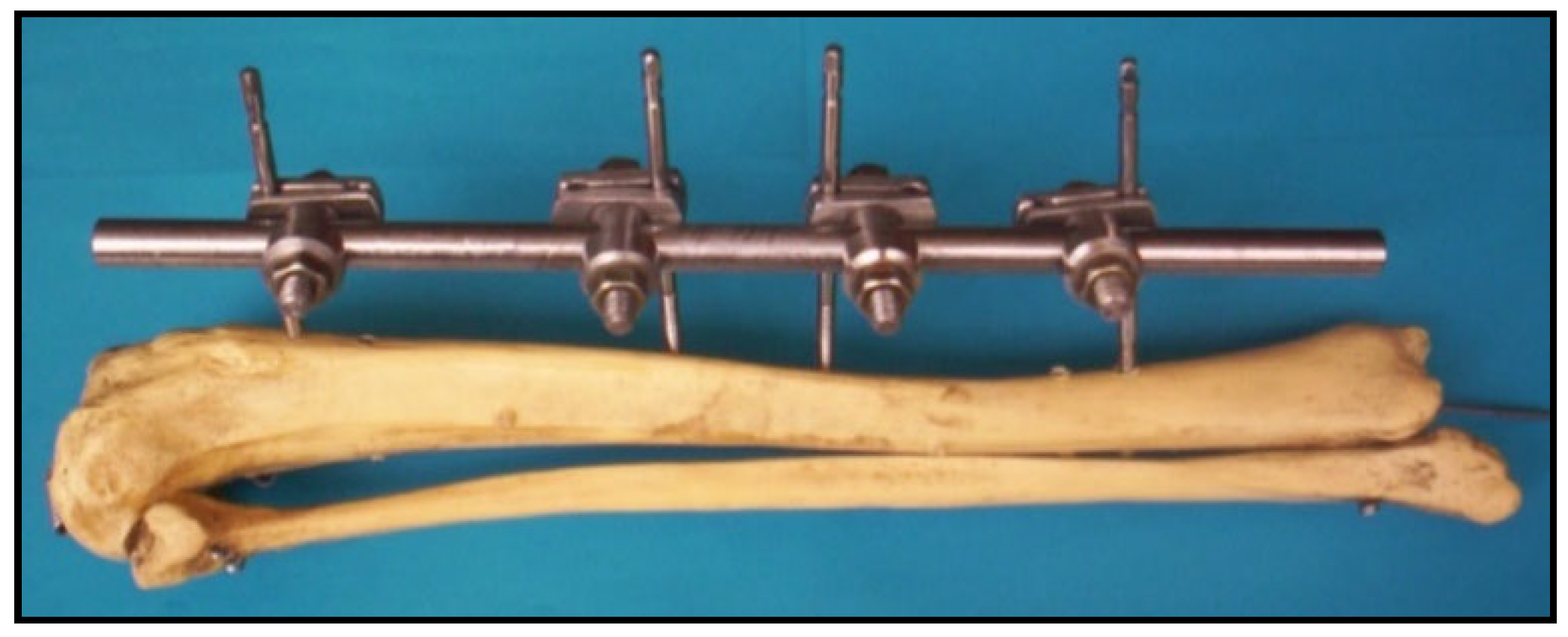
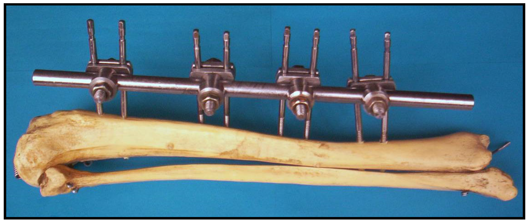
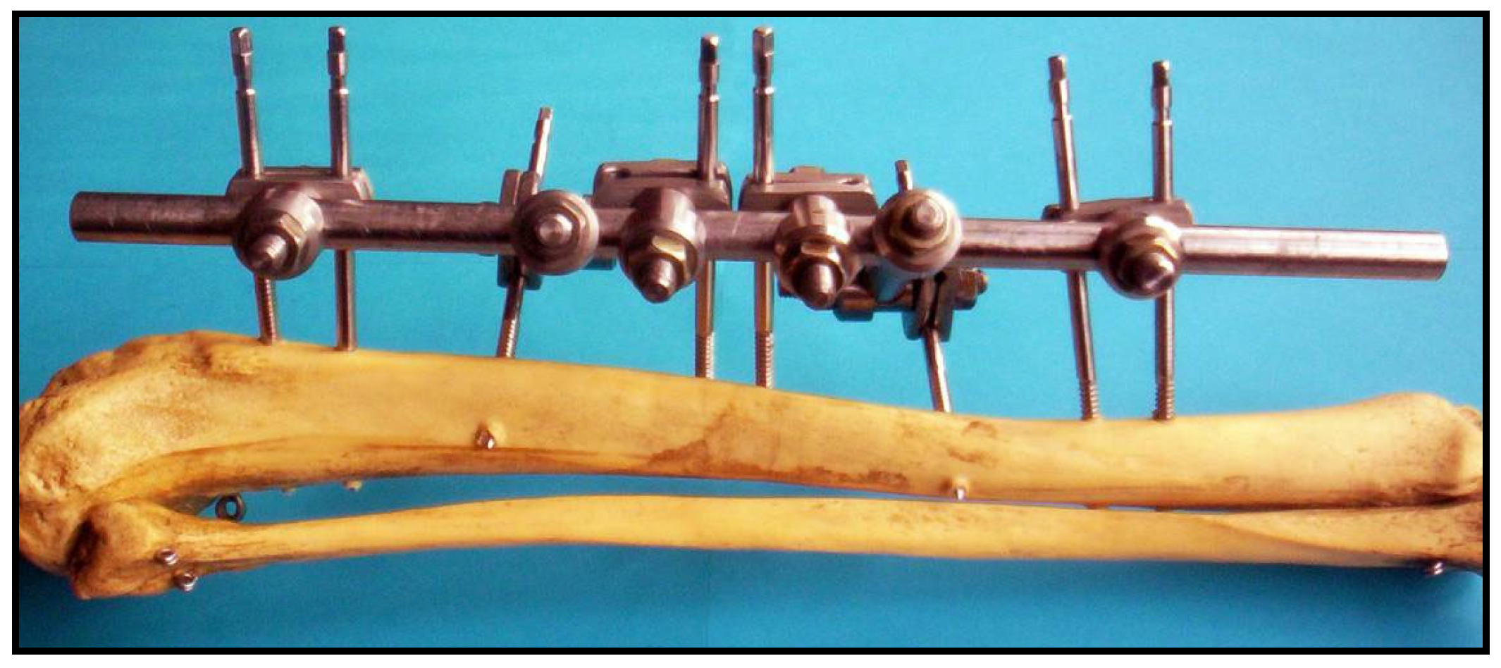
The distance between the fixator rod and the bone model was set to 50 mm, consistent with recommended surgical practice for tibial external fixation. Configurations A and B were uniplanar, with half-pins placed in a single plane (Figure 4 and Figure 5), whereas configurations C and D were biplanar, with half-pins inserted in two planes (Figure 6 and Figure 7). This design enabled comparison of the effects of component position and number (half-pins, clamps, and clamp holders), as well as the interfragmentary gap, on the stability of the fixator configurations.
Configuration A consisted of two half-pins placed in both the proximal and distal bone segments (Figure 4). All half-pins were positioned in the AP plane and oriented parallel to each other. This configuration represents the simplest design, incorporating the fewest structural components of all tested setups.
Configuration B consisted of four half-pins inserted into both the proximal and distal segments of the bone (Figure 5). As in configuration A, all half-pins were positioned in the AP plane and oriented parallel to each other.
Configuration C, like configuration B, consisted of four half-pins placed in both the proximal and distal segments of the bone. However, in configuration C, one half-pin in each segment was positioned in a plane inclined at a 45° angle relative to the AP plane. By means of connector holders, the half-pins were thus arranged in two planes and, together with the other components, formed a triangular (delta) construction that provided biplanar reinforcement of the bone segments (Figure 6).
Configuration D represented a biplanar setup comprising ten half-pins distributed across the proximal and distal bone segments. It essentially extended configuration C by incorporating two additional half-pins positioned in the AP plane (Figure 7).

2.2. Methodology for Evaluating the Stiffness of Fixator Configurations

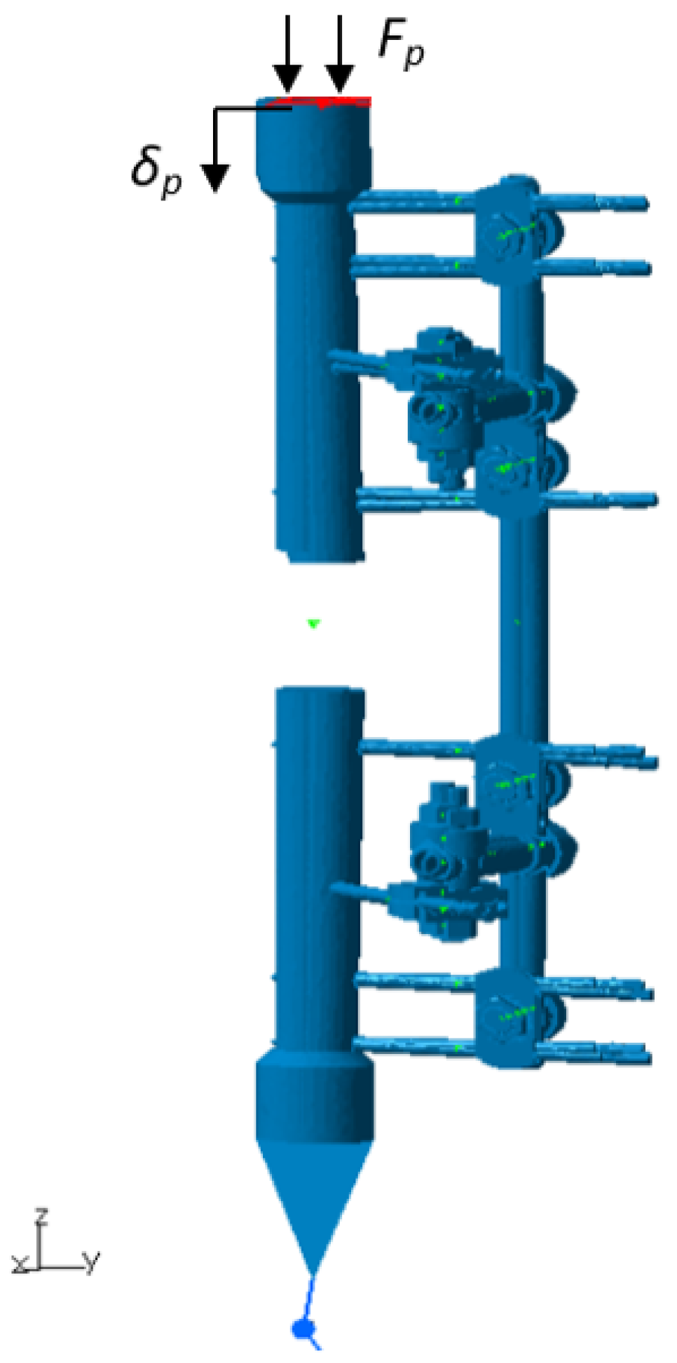
Testing of Sarafix fixator configurations and determination of stiffness under axial loading, anteroposterior (AP) bending, mediolateral (ML) bending, and torsion were performed according to the ASTM F1541 standard (Standard Specification and Test Methods for External Skeletal Fixation Devices) and relevant literature [21,24,41,42,43,44]. For each loading type, the stiffness of the fixator configuration is defined as the ratio of applied load to the displacement or rotation of the bone at the loading site.
The axial compressive stiffness ( C P ) was defined as:
C P = F P δ P
where F P represents the axial compressive force (N), and δ P denotes the axial displacement of the bone segment at the point of load application (mm) (Figure 8).
During axial compression testing, the proximal and distal bone segments were supported by spherical joints. Axial displacement at the load application point was recorded using a calibrated displacement transducer, while the applied compressive force was measured with a force transducer [41].
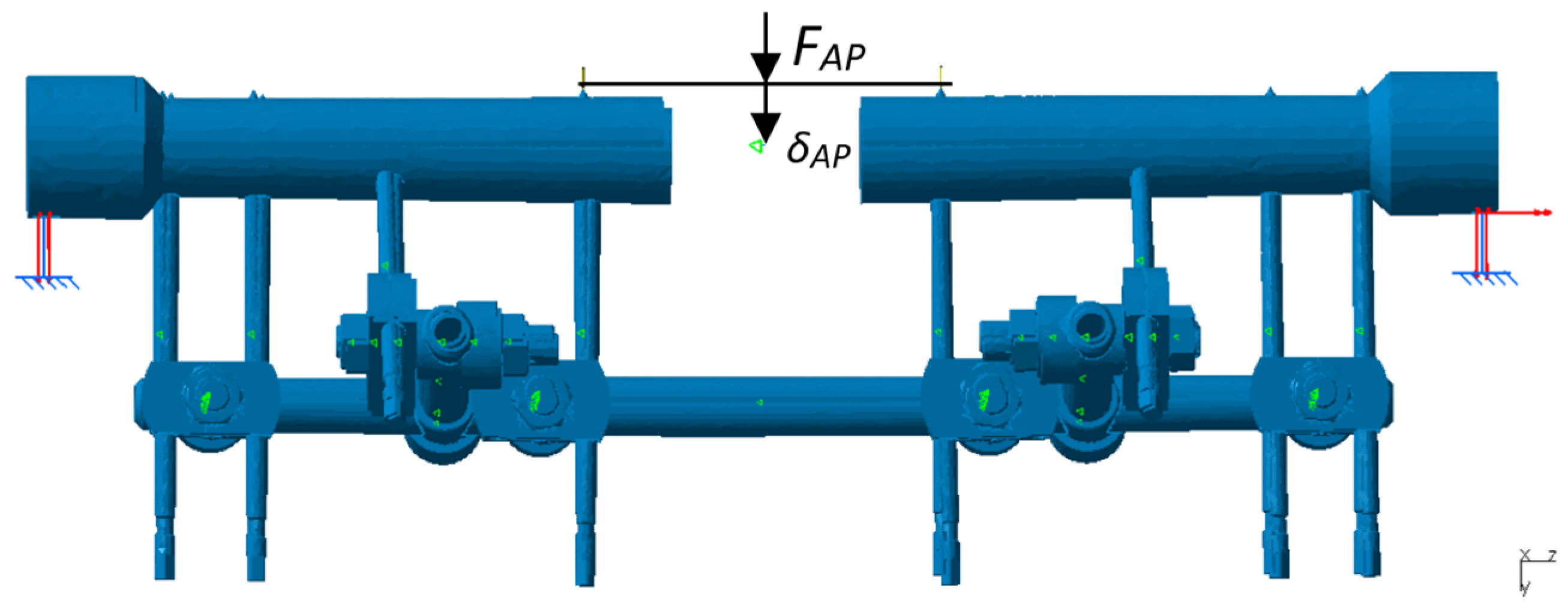
Anteroposterior bending stiffness ( C A P )  and mediolateral bending stiffness ( C M L ) were defined as:
C A P = F A P δ A P C M L = F M L δ M L
where F A P and F M L   represent the bending forces in the AP and ML planes (N), and δ A P and δ M L denote the deflections at the point of load application in the AP and ML planes (mm), respectively (Figure 9 and Figure 10).
Bending tests in the AP and ML directions were performed using the four-point bending method, which is particularly suited for analyzing fixator configurations symmetrical about the fracture plane. During testing, force and deflection were recorded with a force transducer and a displacement transducer, respectively, as in the axial compression test [41].
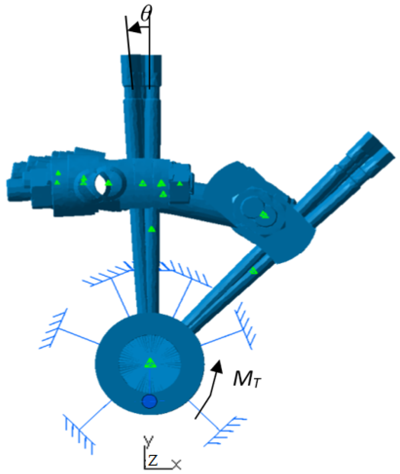
The torsional stiffness of the fixator construct ( C T ) was defined as:
C T = M T θ
where M T is the torsional moment (Nm), and θ is the angular displacement of the distal bone segment at the point of load application (°) (Figure 11).
During torsional testing, a moment was applied about the longitudinal axis of the bone model to the fixator configuration under investigation, while the proximal bone segment was rigidly clamped. Displacement was defined as the relative rotation of the distal segment about the longitudinal axis of the bone model [41].

2.3. Experimental Stress Analysis

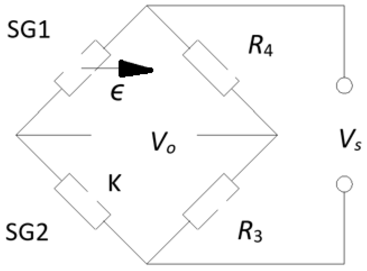
Experimental stress analysis was carried out using linear strain gauges (3/120LY11), a QuantumX data acquisition (DAQ) system, and Catman v3.1 DAQ software (HBM, Hottinger Baldwin Messtechnik GmbH, Darmstadt, Germany). Two full Wheatstone bridges were assembled from active and compensating strain gauges and connected to the QuantumX system. Each bridge configuration consisted of an active strain gauge (SG1) and a compensating (inactive) strain gauge (SG2) (Figure 12). The compensating gauges, identical in type to the active gauges, were mounted on an unloaded metal plate placed near the active gauges on the fixator rod (Figure 13) to eliminate temperature effects. For effective compensation, the plate and the fixator rod were made of the same material [45].
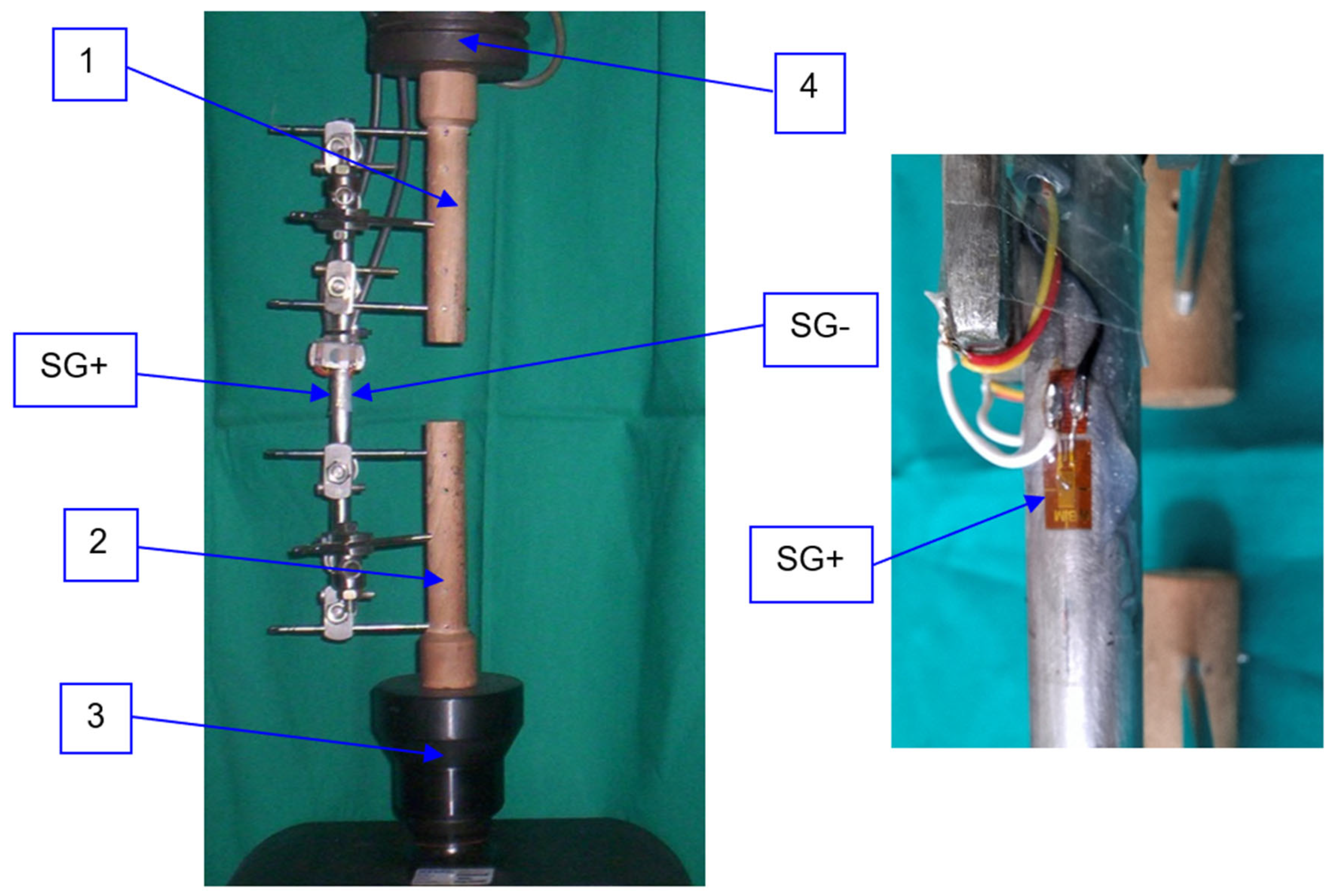
Previous finite element analyses identified critical locations on the fixator rod (SG+ and SG−), providing information on the direction, orientation, and magnitude of the principal stresses [46,47,48]. These studies also indicated that the remaining two principal stresses at the analyzed locations were negligible compared to the maximum and minimum principal stresses. Based on these findings, the active strain gauges were mounted on diametrically opposite sides at the mid-length of the rod: the side closest to the bone model (SG+) to monitor the maximum tensile principal stress ( σ 1 ), and the side farthest from the bone model (SG−) to monitor the maximum compressive principal stress ( σ 3 ) (Figure 13).
Based on the general equation for a Wheatstone bridge:
V o V s = 1 4 R 1 R 1 R 2 R 2 + R 3 R 3 R 4 R 4
or equivalently:
V o V s = K t 4 ϵ 1 ϵ 2 + ϵ 3 ϵ 4
the strain recorded by the strain gauge in the Wheatstone quarter-bridge configuration can be easily obtained, assuming only one active strain gauge:
ϵ = 4 K t V o V s
In Equations (4) and (5), V o represents the output voltage of the Wheatstone bridge, while V s denotes the supply voltage. The terms R 1 through R 4 correspond to the changes in resistance of the strain gauges or resistors within the Wheatstone bridge, and R 1 through R 4 are their initial resistances. The variables ϵ 1 through ϵ 4 indicate the strain measured by each respective gauge, and K t = 1.98 is the gauge factor, i.e., the sensitivity coefficient of the strain gauges [45].
Simultaneous measurement of the absolute values of the maximum positive ( ε 1 ) and maximum negative ( ε 3 ) principal strains on diametrically opposite sides at the mid-length of the fixator rod was performed independently using two separate channels of the QuantumX DAQ system. This setup enabled acquisition of principal strain values at both strain gauge locations individually.
Under axial compression testing, the measured principal strains represent a superposition of bending and compressive components, corresponding to eccentrically applied compressive loading on the fixator rod. In this case, bending strains were substantially greater than the compressive strains. Based on the maximum positive principal strain ( ε 1 ) and the maximum negative principal strain ( ε 3 ), the dominant principal stresses are determined:
σ 1 = ε 1 E σ 3 = ε 3 E
Given that uniaxial stress occurs at the measurement locations in a linearly elastic material, as confirmed by structural analysis [46,47,48], Hooke’s law can be applied in its basic form (Equation (6)).

2.4. Experimental Testing of Fixator Configurations

Experimental testing of the Sarafix fixator configurations was conducted under four loading conditions: axial compression, AP bending, ML bending, and torsion. The maximum load values for each test were defined based on physiological loads typically experienced by external fixators, as reported in in-vivo studies [27,37,49,50,51].
Loading was applied indirectly via the bone model segments. Several pairs of wooden bone models were fabricated to simulate open fractures. Models with an interfragmentary gap of 20 mm had a segment length of 175 mm, while those with a 50 mm gap had a segment length of 160 mm (Figure 13). All models had a diameter of 30 mm and were made of beech wood, selected for its mechanical properties comparable to cortical bone [52,53,54].
One critical factor influencing the biomechanical performance of the fixator is the tightening torque applied to the screw joints on the clamps [21,24,42]. A minimum torque must be ensured to prevent slippage of the joints during testing or clinical use. Any slippage compromises the stability of the entire system and leads to a nonlinear load–displacement response. Therefore, prior to each test, all screw joints of the Sarafix external fixation system were tightened to 20 Nm using a calibrated torque wrench.
After assembly of the Sarafix fixator configurations on the bone models, axial compression testing was performed using a computer-controlled electromechanical universal testing system (Exceed E45.105, MTS Systems Corporation, Eden Prairie, MN, USA). The proximal (1) and distal (2) ends of the bone segments were supported by spherical hinge supports (3 and 4), placed on the lower working surface and the load cell of the testing system (Figure 13).
During axial compression testing, the following parameters were monitored: axial displacement of the proximal bone segment at the load application point, axial load magnitude, and dominant principal stress values at the measurement locations. Axial loading was applied in the range of 0–600 N at a constant rate of 3 N/s.
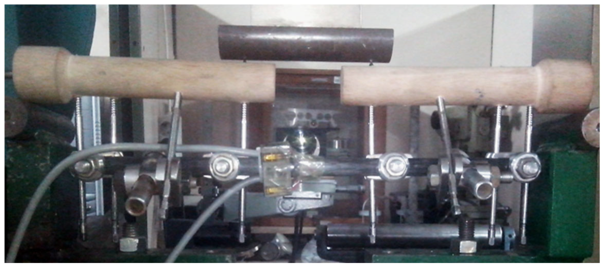
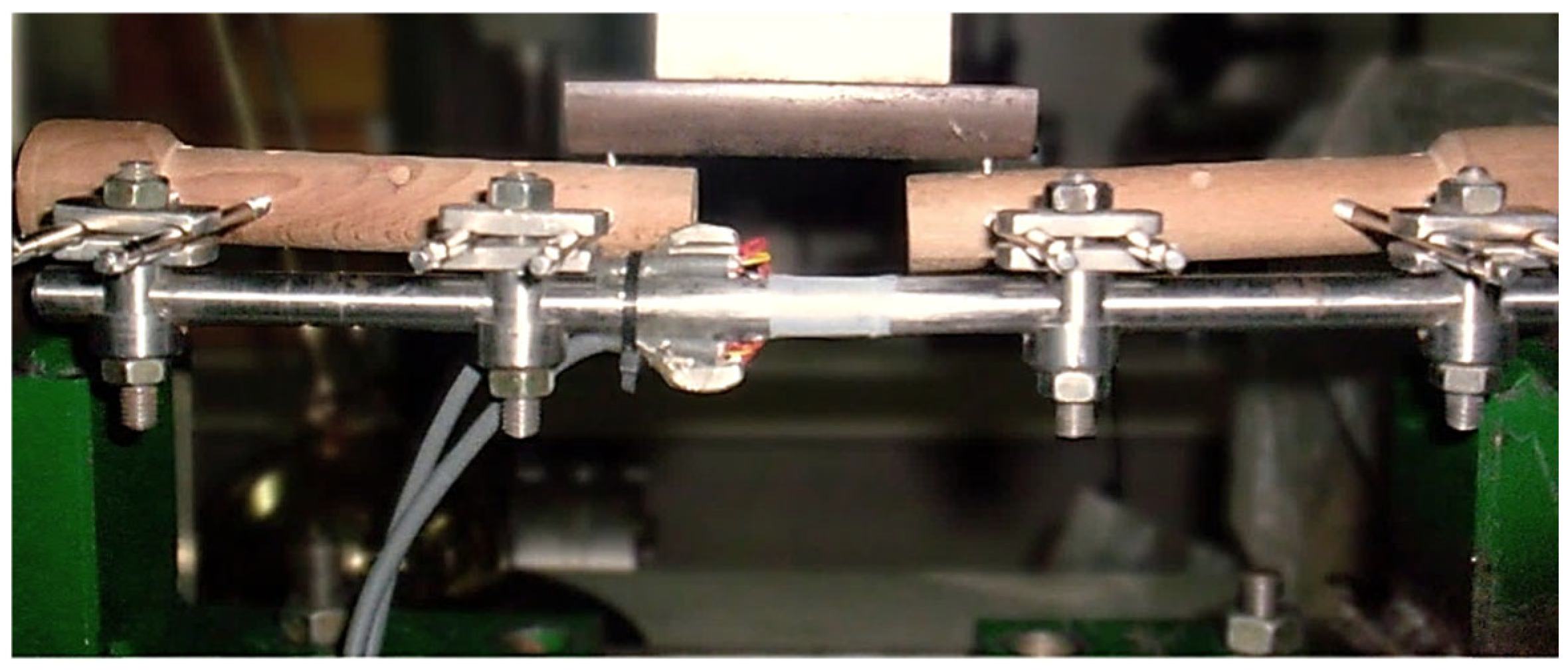
Testing of the Sarafix fixator configurations under AP and ML bending was performed using the same universal testing system as in the axial loading experiments, equipped with a dedicated bone model support fixture (Figure 14 and Figure 15). The load was applied through the tips of two half-wedges positioned on the proximal and distal segments of the bone model, close to the fracture site. This setup corresponds to a four-point bending configuration, in which two equal forces are applied symmetrically between the supports.
During AP and ML bending tests, the monitored parameters included the deflection of the proximal and distal bone segments at the loading points, the magnitude of the bending force, and the dominant principal stress values at the control locations.
Bending loads were applied in the range of 0–500 N at a constant rate of 3 N/s. The support fixture consisted of two horizontally positioned cylindrical rods on which the tibial bone model segments were placed (Figure 14 and Figure 15). The distance between the central axes of the rods was 362 mm. The spacing between the loading points on the adjacent bone segments was 60 mm for an interfragmentary gap of 20 mm and 90 mm for a gap of 50 mm.
Torsional testing of the Sarafix fixator configurations was carried out using a Maximat V13 universal lathe (EMCO GmbH, Salzburger Str. 80, 5400 Hallein, Austria). The proximal bone segment was secured in the lathe chuck, while the distal segment was mounted in a standard ball bearing (type 6208-Z, SKF Group, Hornsgatan 1, SE 415 50 Göteborg, Sweden) using a custom-designed support fixture. The fixture, attached to the lathe carriage (1), consisted of a bearing holder (2) and an adapter (3) (Figure 16).
Torsional loads were applied to the fixator configurations using a calibrated torque wrench (model TEI 12-FU, Snap-on Tools Corp., 2801 80th Street, Kenosha, WI 53143-1410, USA) within a range of 0–15 Nm. During testing, the monitored parameters included the angular rotation of the distal bone segment at the point of torque application and the magnitude of the applied torque.

3. Results

3.1. Results of Axial Compression Testing

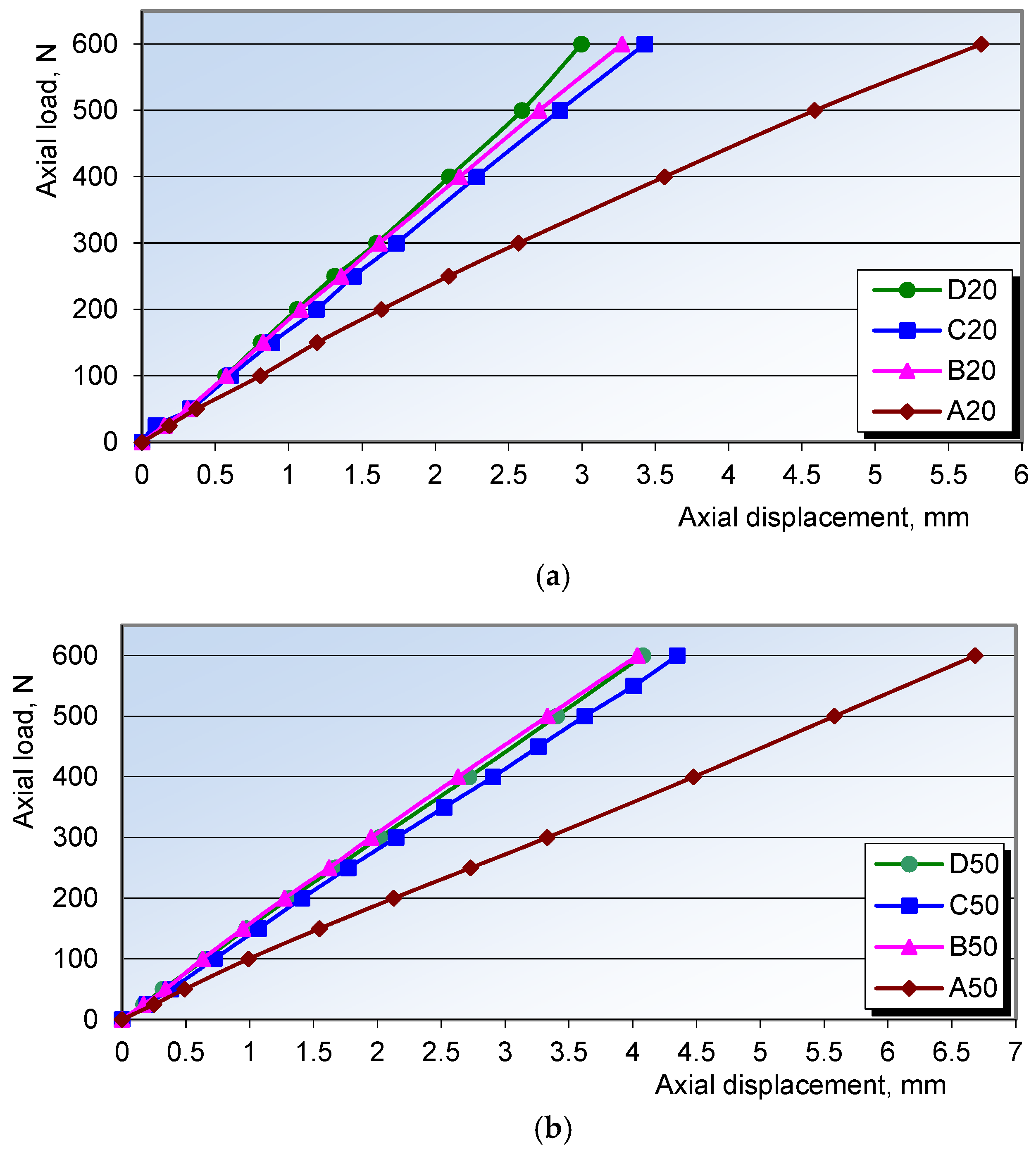
The experimental results for the Sarafix fixator configurations are presented as axial load–displacement diagrams for interfragmentary gaps of 20 mm (Figure 17a) and 50 mm (Figure 17b).
The experimental results, together with their statistical analysis using ANOVA (Table 2) and post hoc tests (Table 3), showed that under axial compressive loading the most influential factor affecting construct stiffness was the number of half-pins.
This effect was particularly evident when comparing configuration A50 (four half-pins) with B50 (eight half-pins) (p = 0.006). In contrast, planarity (comparison of configurations B and C) and interfragmentary distance (comparison of the same configurations at 20 mm and 50 mm) did not have a statistically significant effect on displacements under axial compression.
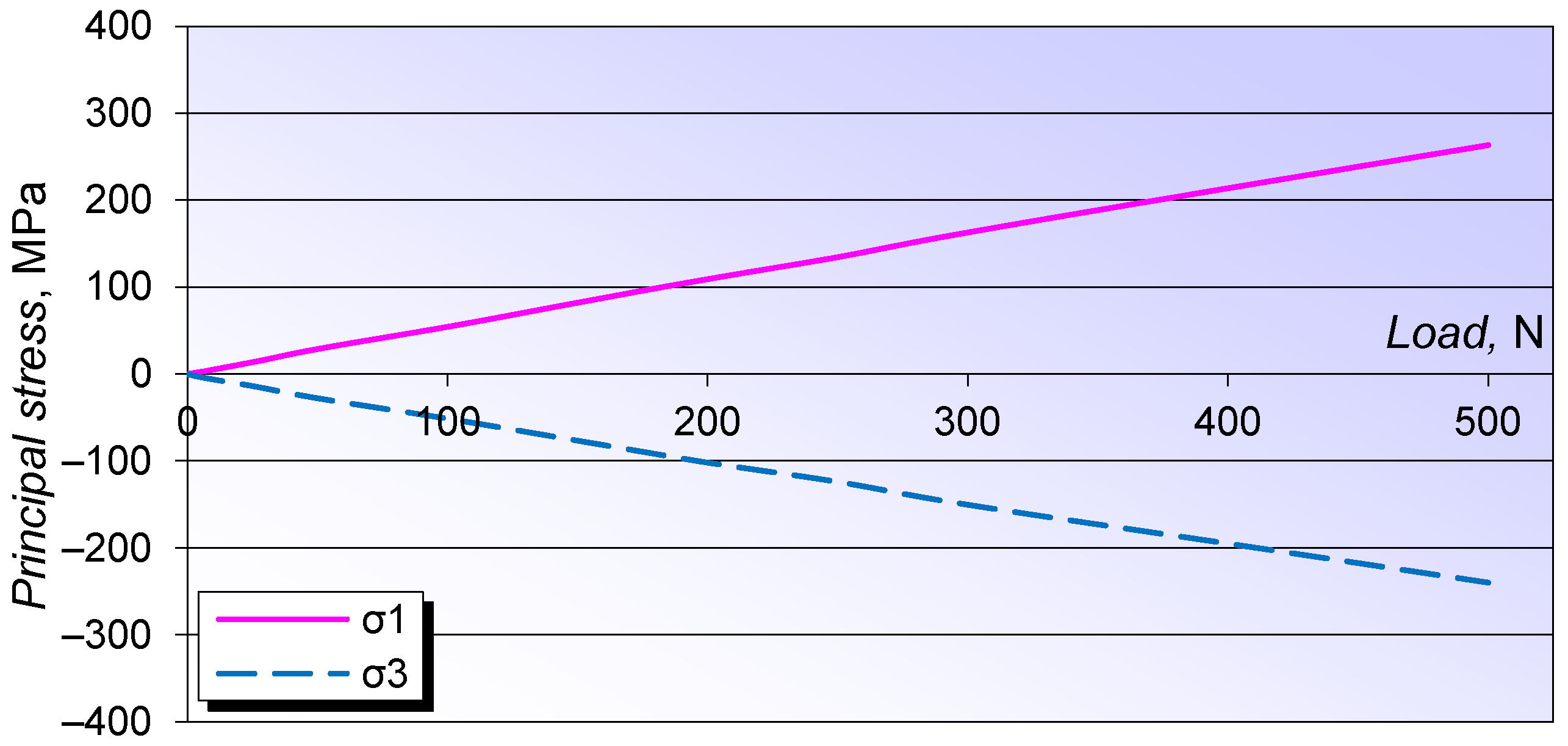
Differences in principal stress values between the tested configurations were minimal. Therefore, the analysis of maximum and minimum principal stresses is presented as principal stress–axial load diagrams only for configurations A and B with interfragmentary gaps of 20 mm (Figure 18a) and 50 mm (Figure 18b). A linear relationship was observed between principal stresses and axial load, with compressive principal stress ( σ 3 ) consistently exceeding tensile principal stress ( σ 1 ) across all configurations. As previously noted, this behavior results from the superposition of bending and compressive stresses in the fixator rod due to eccentric axial loading.
The axial stiffness values and principal stresses for all analyzed configurations are summarized in Table 4. The principal stresses at the measurement locations were highly uniform across configurations and remained well below the yield strength of the fixator rod material.
Based on the obtained results and statistical analysis, it can be concluded that configurations B and D exhibited comparable performance under axial compressive loading, despite differences in their structure and geometry.

3.2. Test Results for Four-Point AP and ML Bending

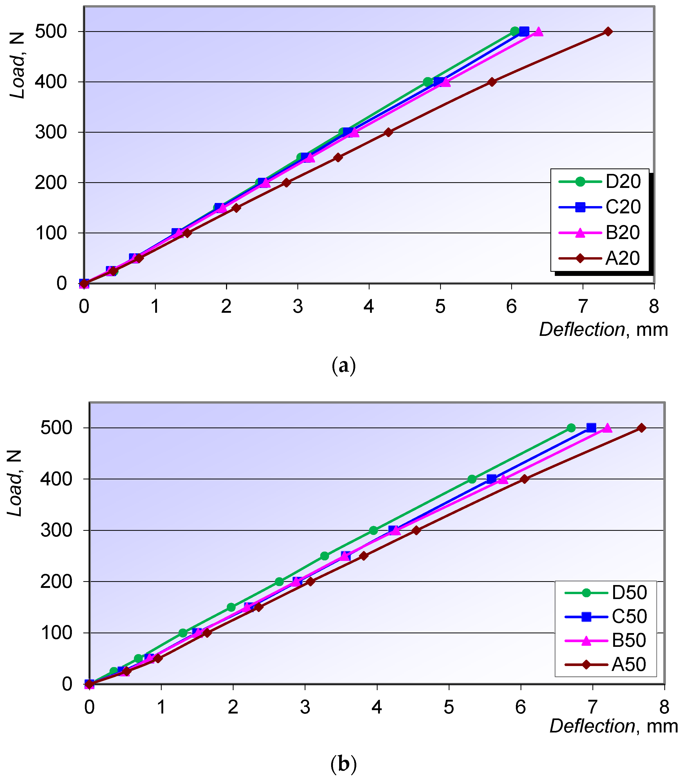
The AP bending results for the Sarafix fixator configurations are presented as load–deflection diagrams for interfragmentary distances of 20 mm (Figure 19a) and 50 mm (Figure 19b). A predominantly linear load–deflection relationship was observed, indicating elastic behavior within the applied load range.
Statistical analysis of the data using ANOVA revealed no statistically significant differences among the configurations or analyzed parameters with respect to deflections under AP bending (Table 5).
Since the differences in principal stress values at the control points among the configurations were negligible, the stress analysis results for the maximum and minimum principal stresses are presented as stress–load dependence diagrams exclusively for the B50 configuration (Figure 20).
Under AP bending, unlike in axial loading, the absolute value of the minimum principal stress ( σ 3 ) is approximately equal to that of the maximum principal stress ( σ 1 ).
The maximum deflection values at the loading site, which were used to determine the AP bending stiffness of the fixator configurations, are presented in Table 6. The table also includes the maximum principal stress values at the analyzed locations. The results show that the magnitudes of the principal stresses at the measurement sites are relatively uniform across all configurations.
The test results for ML bending of the Sarafix fixator configurations with interfragmentary gaps of 20 mm and 50 mm are presented as load–deflection diagrams (Figure 21a,b).
For ML bending, as for AP bending, statistical analysis using ANOVA revealed no statistically significant differences among the configurations or analyzed parameters with respect to deflections (Table 7).
Since the differences in principal stress values among the configurations were negligible, the results of the principal stress analysis at the mid-point of the fixator rod are presented as stress–load diagrams only for the B50 configuration, consistent with the approach used for AP bending (Figure 22).
Similar to AP bending, the absolute value of the minimum principal stress ( σ 3 ) is approximately equal to that of the maximum principal stress ( σ 1 ).
The maximum deflections at the loading site, which were used to determine the ML bending stiffness of the fixator configurations, together with the maximum principal stress values, are presented in Table 8.
Comparison of the AP and ML bending results shows that deflections are significantly greater under ML bending, as the bending plane does not intersect the configuration frame as it does in AP bending. Moreover, the principal stresses at the analyzed points of the fixator configurations are higher under ML bending.

3.3. Torsional Testing Results

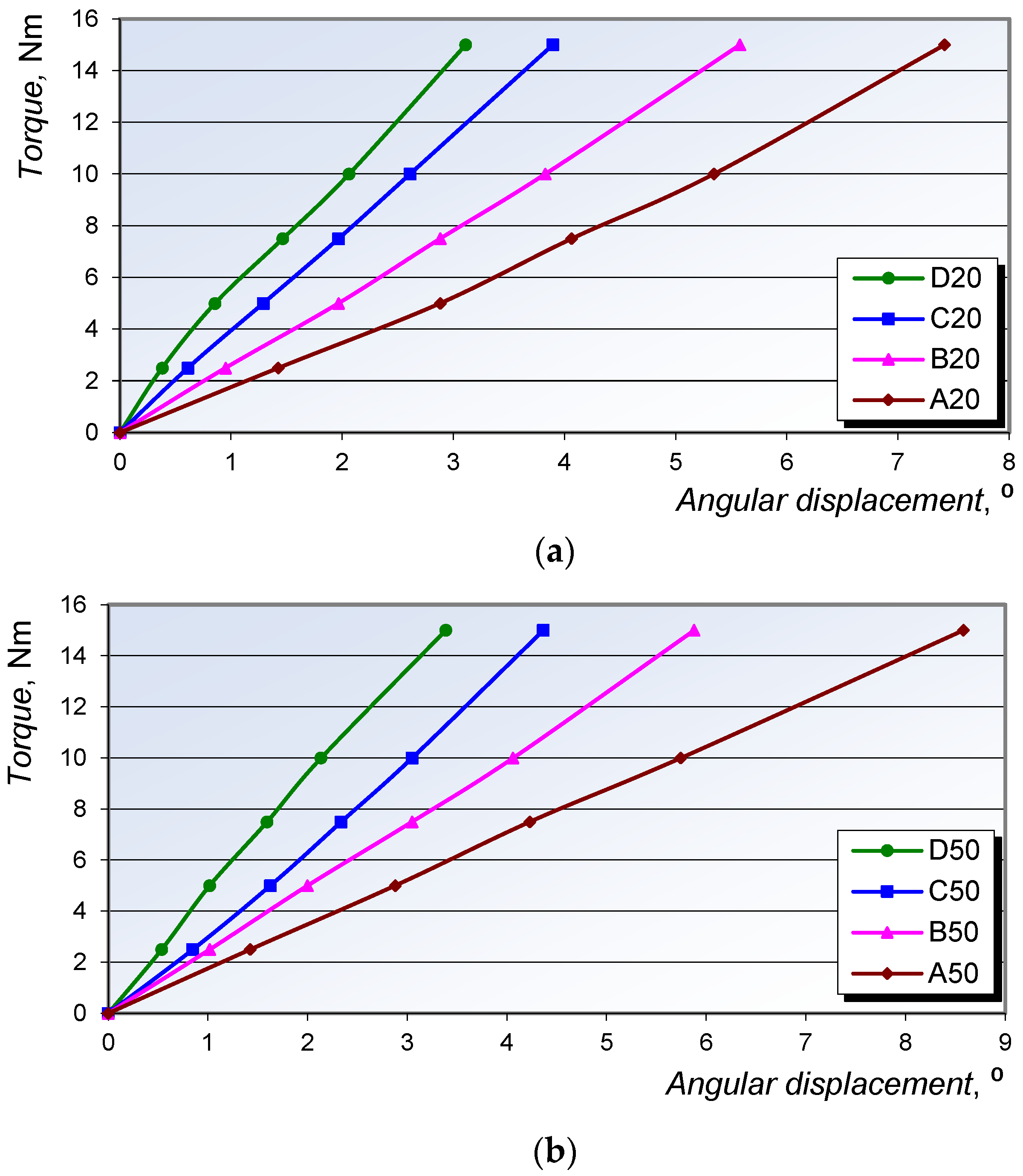
The torsional test results of the Sarafix fixator configurations are presented as torque–angular displacement diagrams at the loading site for configurations A, B, C, and D with interfragmentary distances of 20 mm (Figure 23a) and 50 mm (Figure 23b).
During torsional loading, the advantages of the biplanar configurations (C and D) become evident due to the placement of half-pins in two planes. This arrangement forms a triangular (delta) structure that provides substantially higher torsional stiffness compared to the uniplanar configurations (A and B).
The experimental results, together with their statistical analysis using ANOVA (Table 9) and post hoc tests (Table 10), indicate that torsional stiffness is influenced by two key parameters: configuration planarity and the number of half-pins.
Specifically, comparisons between configurations B20 and C20 (p = 0.021) and B50 and C50 (p = 0.036) reveal a statistically significant effect of planarity on angular displacement. Likewise, comparisons of A20 versus B20 (p = 0.043) and A50 versus B50 (p < 0.001) show that the number of half-pins also significantly affects angular displacement. In contrast, the interfragmentary distance (20 mm vs. 50 mm) did not demonstrate a statistically significant influence on angular displacement under torsional loading.
The maximum angular displacements, used to determine the torsional stiffness of the fixator configurations, are presented in Table 11.

4. Discussion

External fixation remains the preferred method for stabilizing complex fractures, especially those caused by high-energy trauma such as gunshot and explosive injuries. Due to the specific period in which it was developed, the Sarafix external fixation system was first subjected to clinical testing on the most severe war-related open fractures, and later to biomechanical investigations.
In the absence of significant joint slippage, rotational displacements, or plastic deformation of fixator components—which are essential to maintaining anatomical reduction of bone fragments under postoperative loading—a linear relationship between load and segment displacement is required [12,55]. The results of this study confirmed a linear correlation between load and displacement, as well as between load and principal stress, for all tested configurations.
The analysis did not reveal any significant influence of configuration type or the tested parameters on the principal stresses generated at the monitored control points. The highest principal stresses were recorded under axial loading but remained well below the yield strength of the fixator rod material.
The study identified the number of half-pins as the statistically most influential factor affecting the axial stiffness of the fixator, which is consistent with findings reported in previous studies [56,57]. The significance of configuration planarity on fixator stiffness was also confirmed, particularly under torsional loading, where biplanar configurations demonstrated superior performance compared to monoplane configurations, in agreement with the findings of [58]. The parameter interfragmentary distance did not show a statistically significant effect on fixator stiffness under any of the loading conditions tested. It can therefore be concluded that the interfragmentary distance does not substantially influence configuration stability, which represents one of the advantages of the Sarafix fixator.
When general conclusions are drawn regarding configurations applied to tibial fractures, configuration D consistently exhibited the highest overall stiffness across all loading conditions. However, statistically significant differences in axial stiffness were observed only between configuration D and configuration A, and in one comparison with configuration C. For AP and ML bending, no significant differences in bending stiffness were found between configurations. However, in torsional loading, planarity emerged as a significant factor, with only the comparison between biplanar configurations C and D being statistically non-significant. In this case, both planarity and the number of half-pins had statistically significant influence.
It is worth emphasizing that biplanar configurations C and D are better suited to the anatomical geometry of the tibia, allowing placement of half-pins in regions with larger cross-sectional areas, which improves pin–bone interface strength. Given the asymmetric shape, variable cross-section, and anatomically challenging pin placement areas of the tibia, biplane fixation offers a clear mechanical advantage. Based on the presented findings, configuration C is recommended for clinical use in open tibial fractures, as it provides adequate stability under all loading conditions with an optimal structural layout. This recommendation primarily reflects the balance between its superior biomechanical performance across all tested loading scenarios (particularly torsion) and its lower structural complexity. Additionally, configuration C is more anatomically aligned with the tibial geometry and offers greater flexibility in selecting pin insertion sites, thereby enhancing its practical applicability and overall clinical feasibility. On the other hand, the use of configuration A for open tibial fractures is not recommended due to insufficient stability under all analyzed loading conditions, particularly under axial compressive loading and torsion.
Clinical studies [38,40] have demonstrated the high efficacy of the Sarafix system in treating complex open fractures caused by shrapnel injuries, with outcomes comparable to those achieved using circular external fixators [59].
A study [60] of three unilateral fixators (Meyrueis’s, Noor’s, and Hoffmann 3) in both uniplanar and biplanar (dual-rod) configurations revealed that uniplanar designs exhibited significantly lower axial stiffness (48.9, 71.8, and 35 N/mm, respectively) compared to the Sarafix uniplanar configurations. Similar trends were observed under ML bending, with respective stiffness values of 4.4, 4.7, and 6.5 N/mm. Only under torsional loading did the compared fixators achieve similar results, with torsional stiffness of 1.8, 1.6, and 0.8 Nm/deg, respectively, in comparison to Sarafix. As expected, dual-rod configurations of the same systems showed higher axial stiffness (234.7, 228.2, and 98.8 N/mm, respectively), while ML bending stiffness (62.2, 48.3, and 15.2 N/mm, respectively) and especially torsional stiffness (1.5, 1.6, and 1.0 Nm/deg, respectively) were lower compared to Sarafix.
Table 12 provides a quantitative comparison of the biomechanical stiffness of the Sarafix fixator with several commercially available external fixation systems.
Testing of the UNI-FIX (ProSpon, Kladno, Czech Republic) unilateral fixator [33] reported an axial stiffness of 120 N/mm, which is lower than that of the Sarafix configuration B20, considered the most relevant among the configurations tested.
Other studies have reported axial stiffness values for different unilateral fixators: 114 N/mm (Dynamix DFS, Ebifix, Iowa, USA) and 320 N/mm (OrthofixProCallus system, Verona, Italy) [17]. The OrthofixProCallus fixator exhibited higher axial stiffness than the Sarafix, but such results are expected due to differences in design intent and material properties.
Similarly, the commercial OrthofixModulsystem and its redesigned version demonstrated higher axial stiffness (261 and 255 N/mm, respectively) and AP bending stiffness (220 and 294 N/mm) compared to Sarafix [32].
Tests conducted according to the ASTM F1541 standard on a prototype unilateral fixator revealed stiffness values of 117 N/mm (axial), 46 N/mm (AP bending), 8.6 N/mm (ML bending), and 5.8 Nm/deg (torsional) [30]. Comparative testing of commercial fixators Hofmann 3 and Hofmann II MRI reported AP bending stiffness of 31 and 16 N/mm, ML bending stiffness of 59 and 43 N/mm, and torsional stiffness of 1.03 and 0.61 Nm/deg, respectively [33]. In testing of the Dynafix (EBI) fixator in a neutral configuration, the reported stiffness values were: 340 N/mm in axial compression, 230 N/mm in AP bending, 62 N/mm in ML bending, and 3.2 Nm/deg in torsion [42].
Taken together, these findings highlight that the Sarafix fixator provides a balanced combination of stiffness, structural simplicity, and adaptability to tibial anatomy, placing it competitively among commercial external fixators.
Further research on the Sarafix fixator was directed toward the development of a Knowledge-Based Engineering (KBE) system for structural dimensional optimization of the fixator design, which resulted in improvements of the existing construction in terms of reduced weight, displacement, and stress, while simultaneously increasing stiffness [46]. On the other hand, studies were also conducted on the introduction of composite materials into the existing fixator design, which, in addition to reducing weight and stress, further achieved radiotransparency [61].

5. Limitations

The present research was conducted in accordance with ASTM F1541, which specifies both static and dynamic testing requirements for external fixator configurations. In this study, detailed static tests were performed under axial, AP bending, ML bending, and torsional loading, with concurrent stress monitoring on the fixator rod. However, dynamic cyclic testing under axial loading, as prescribed by the standard, was not included.
The experiments were carried out on wooden bone models, with loading rates of 3 N/s for axial and bending tests and 1 Nm/s for torsional tests. In contrast, physiological loading is inherently dynamic, typically reaching its full magnitude within 0.5–1 s [37,50].
Moreover, the present study did not analyze interfragmentary displacements at the fracture site under different loading modes—parameters that directly influence fracture healing and bone consolidation, as highlighted in previous studies [46,47,48,62].

6. Conclusions

The comparative analysis of different fixator configurations provides valuable guidance for orthopedic surgeons in understanding fixation mechanics, the influence of design parameters on construct stability, and in preoperatively selecting the most appropriate configuration to reduce healing time and minimize the risk of non-union. Excessive rigidity in fixator constructs may result in delayed union or non-union, whereas overly elastic configurations can increase the risk of pin-site infection, malunion, or impaired fracture healing.
This study establishes direct relationships between fixator configuration type and stiffness under axial compression, AP bending, ML bending, and torsional loading. Based on these relationships, statistical analysis was used to assess the influence of key design parameters (number of half-pins, configuration planarity, and interfragmentary distance) on construct stiffness. A statistically significant effect of the number of half-pins was observed for both axial and torsional stiffness, while configuration planarity significantly affected torsional stiffness only. Interfragmentary distance did not demonstrate a statistically significant influence under any of the tested loading conditions. Continuous stress monitoring at critical locations of the fixator rod confirmed a linear load–stress relationship, with stress levels substantially below the material yield strength.
The biomechanical experiments demonstrated that biplanar fixator configurations ensure sufficient stability of open tibial fractures under axial loading, AP and ML bending, and torsional loading. The investigated fixator system features a simple and technologically efficient design, straightforward application, the possibility of placing half-pins in two planes using a single rod, and a clamp design that accommodates dual-pin fixation. These characteristics result in a versatile construct capable of forming a wide range of uniplanar and biplanar configurations applicable across the musculoskeletal system, while also ensuring free access to the wound for monitoring and potential secondary interventions.
This research defines an appropriate structural and geometric basis for achieving adequate fracture stability while enabling controlled dynamization, which stimulates and accelerates the consolidation process. Preoperative selection of the optimal fixator configuration thus facilitates surgical planning and reduces the risk of complications such as non-union or pseudoarthrosis.
Given its demonstrated biomechanical properties and clinical efficacy in managing complex open fractures, the investigated low-cost external fixation system can be considered comparable to well-established commercial fixators. Future research should investigate the effect of half-pin insertion angle relative to the AP plane on construct stability, incorporate dynamic and in vivo testing, and further explore the integration of advanced materials into fixator design.

Author Contributions

Conceptualization, E.M. and A.M.; methodology, E.M. and A.M.; software, E.M.; validation, E.M.; formal analysis, E.M. and N.P.; investigation, E.M., N.P., A.M., E.R. and B.M.; resources, E.M., N.P. and A.M.; data curation, E.M., E.R. and B.M.; writing—original draft preparation, E.M. and N.P.; writing—review and editing, E.M., N.P., A.M., E.R. and B.M.; visualization, E.M. and N.P.; supervision, E.M., N.P. and A.M.; project administration, E.M., N.P., E.R. and B.M.; funding acquisition, E.M. and N.P. All authors have read and agreed to the published version of the manuscript.

Funding

This work was supported by the Federal Ministry of Education and Science of Bosnia and Herzegovina [grant number: 0101-7991-13/18, 2018].

Institutional Review Board Statement

Not applicable.

Informed Consent Statement

Not applicable.

Data Availability Statement

Data will be made available on request.

Conflicts of Interest

The authors declare that they have no known competing financial interests or personal relationships that could have appeared to influence the work reported in this paper.

References

  1. Behrens, F. A Primer of Fixator Devices and Configurations. Clin. Orthop. 1989, 241, 5–14. [Google Scholar] [CrossRef]
  2. Behrens, F.; Searls, K. External fixation of the tibia. Basic concepts and prospective evaluation. J. Bone Jt. Surg. 1986, 68, 246–254. [Google Scholar] [CrossRef] [PubMed]
  3. Behrens, F. General Theory and Principles of External Fixation. Clin. Orthop. 1989, 241, 15–23. [Google Scholar] [CrossRef]
  4. Karunakar, M.A.; Bosse, M.J. Principles of External Fixation. In Rockwood & Green’s: Fractures, 5th ed.; LWW: New York, NY, USA, 2001; Chapter 7. [Google Scholar]
  5. Agrawal, H.K.; Garg, M.; Singh, B.; Jaiman, A.; Khatkar, V.; Khare, S.; Batra, S.; Sharma, V.K. Management of complex femoral nonunion with monorail external fixator: A prospective study. J. Clin. Orthop. Trauma 2016, 7, 191–200. [Google Scholar] [CrossRef]
  6. Simpson, A.H.R.W.; Robiati, L.; Jalal, M.M.K.; Tsang, S.T.J. Non-union: Indications for external fixation. Injury 2019, 50, S73–S78. [Google Scholar] [CrossRef]
  7. Bliven, E.K.; Greinwald, M.; Hackl, S.; Augat, P. External fixation of the lower extremities: Biomechanical perspective and recent innovations. Injury 2019, 50, S10–S17. [Google Scholar] [CrossRef]
  8. Abd Aziz, A.U.; Abdul Wahab, A.H.; Abdul Rahim, R.A.; Abdul Kadir, M.R.; Ramlee, M.H. A finite element study: Finding the best configuration between unilateral, hybrid, and ilizarov in terms of biomechanical point of view. Injury 2020, 51, 2474–2478. [Google Scholar] [CrossRef]
  9. Emami, A.; Mjoberg, B.; Karlstrom, G.; Larsson, S. Treatment of closed tibial shaft fractures with unilateral external fixation. Injury 1995, 26, 299–303. [Google Scholar] [CrossRef]
  10. Perren, S.M. Evolution of the internal fixation of long bone fractures. The scientific basis of biological internal fixation: Choosing a new balance between stability and biology. J. Bone Jt. Surg. Br. 2002, 84, 1093–1100. [Google Scholar]
  11. Chao, E.Y.; Inoue, N. Biophysical stimulation of bone fracture repair, regeneration and remodelling. Eur. Cell Mater. 2003, 6, 72–84; discussion 84–85. [Google Scholar] [CrossRef] [PubMed]
  12. Fleming, B.; Paley, D.; Kristiansen, T.; Pope, M. A biomechanical analysis of the Ilizarov external fixator. Clin. Orthop. Relat Res. 1989, 241, 95–105. [Google Scholar] [CrossRef] [PubMed]
  13. Pollack, A.; Ziran, B.H. Principles of External Fixators, Skeletal Injury, 3rd ed.; Browner and Jupiter, Ed.; W.B. Saunders: Philadelphia, PA, USA, 2003; Volume 1, Chapter 9; pp. 179–194. [Google Scholar]
  14. Heim, D.; Regazzoni, P.; Perren, S.M. Current use of external fixation in open fractures. Injury 1992, 23 (Suppl. 2), S1–S35. [Google Scholar]
  15. Terzini, M.; Sicuranza, S.; Alberghina, F.; Ravera, L.; Aloj, D.C.; Bignardi, C. Evaluation of the Structural Behaviour of a Unilateral External Fixator for Osteosynthesis. Open Biomed. Eng. J. 2021, 15, 29–36. [Google Scholar] [CrossRef]
  16. Giotakis, N.; Narayan, B. Stability with unilateral external fixation in the tibia. Strateg. Trauma Limb Reconstr. 2007, 2, 13–20. [Google Scholar]
  17. Burgers, P.T.P.W.; Van Riel, M.P.J.M.; Vogels, L.M.M.; Stam, R.; Patka, P.; Van Lieshout, E.M.M. Rigidity of unilateral external fixators—A biomechanical study. Injury 2011, 42, 1449–1454. [Google Scholar] [CrossRef]
  18. Loi, F.; Córdova, L.A.; Pajarinen, J.; Lin, T.; Yao, Z.; Goodman, S.B. Inflammation, fracture and bone repair. Bone 2016, 86, 119–130. [Google Scholar] [CrossRef] [PubMed]
  19. Fernando, P.L.N.; Abeygunawardane, A.; Wijesinghe, P.C.I.; Dharmaratne, P.; Silva, P. An engineering review of external fixators. Med. Eng. Phys. 2021, 98, 91–103. [Google Scholar] [PubMed]
  20. Yang, L.; Saleh, M.; Nayagam, S. The Effects od Different Wire and Screw Combinations on the Stiffness of a Hybrid External Fixator. Proc. Inst. Mech. Eng. Part H J. Eng. Med. 2000, 214, 669–676. [Google Scholar]
  21. Vossoughi, J.; Youm, Y.; Bosse, M.; Burgess, A.R.; Poka, A. Structural Stiffness of the Hoffmann Simple Anterior Tibial External Fixation Frame. In Proceedings of the 5th Southern Biomedical Engineering Conference, Baton Rouge, LA, USA, 20–21 October 1986. [Google Scholar]
  22. Alkalay, R.N.; Sharpe, D.; Bader, D.L. The effects of design and configuration on the biomechanical response of an internal spinal fixator. Proc. Inst. Mech. Eng. Part H J. Eng. Med. 1999, 213, 137–146. [Google Scholar] [CrossRef]
  23. Moroz, T.K.; Finlay, J.B.; Rorabeck, C.H.; Bourne, R.B. Stability of the Original Hoffmann and AO Tubular External Fixation Devices. Med. Biol. Eng. Comput. 1988, 26, 271–276. [Google Scholar]
  24. Remiger, A.R. Mechanical Properties of the Pinless External Fixator on Human Tibiae. Br. J. Accid. Surg. Inj. 1992, 23 (Suppl. 3), S28–S42. [Google Scholar] [CrossRef]
  25. Kumara, R.; Guptab, R.C.; Mishra, S. Experimental Testing of Joshi’s External Stabilizing System (JESS) under Axial Compression. Int. J. Eng. Res. Technol. 2014, 3, 599–603. [Google Scholar]
  26. Martins Amaro, A.; Fátima Paulino, M.; Manuel Roseiro, L.; Augusta Neto, M. The Effect of External Fixator Configurations on the Dynamic Compression Load: An Experimental and Numerical Study. Appl. Sci. 2020, 10, 3. [Google Scholar] [CrossRef]
  27. Simpson, A.H.R.W.; Cunningham, J.L.; Kenwright, J. The Forces which Develop in the Tissues During Leg Lenghtening: A Clinical Study. J. Bone Jt. Surg. Br. Vol. 1996, 78, 979–983. [Google Scholar] [CrossRef]
  28. Windolf, M.; Varjas, V.; Gehweiler, D.; Schwyn, R.; Arens, D.; Constant, C.; Zeiter, S.; Richards, R.G.; Ernst, M. Continuous implant load monitoring to assess bone healing status—Evidence from animal testin. Medicina 2022, 58, 858. [Google Scholar] [CrossRef] [PubMed]
  29. Feist, A.; Hetreau, C.; Ernst, M.; Varga, P.; Schwarzenberg, P. Sensor-validated simulations predict fracture healing outcomes in an ovine model. Results Eng. 2025, 25, 104518. [Google Scholar] [CrossRef]
  30. Carrera-Pinzón, A.F.; Leyton, A.; Machado Caicedo, A.; García, J.J.; Casanova, F. Development of an easy-to-assemble external fixation system for bone transport. DYNA 2019, 86, 53–59. [Google Scholar]
  31. Sellei, R.M.; Kobbe, P.; Dienstknecht, T.; Lichte, P.; Pfeifer, R.; Behrens, M.; Brianza, S.; Pape, H.-C. Biomechanical properties of different external fixator frame configurations. Eur. J. Trauma Emerg. Surg. 2014, 41, 313–318. [Google Scholar] [CrossRef]
  32. Pavić, A.; Kodvanj, J.; Surjak, M. Determining the stability of novel external fixator by using measuring system Aramis. Tech. Gaz. 2013, 20, 995–999. [Google Scholar]
  33. Padovec, Z.; Růžička, P.; Sedláček, R.; Růžička, M. Design, analysis and testing of an external fixation device manufactured from composite materials. Appl. Comput. Mech. 2017, 11, 145–154. [Google Scholar] [CrossRef]
  34. Sellahewa, T.; Weerasinghe, C.; Silva, P. Biomechanical Evaluation Method to Optimize External Fixator Configuration in Long Bone Fractures—Conceptual Model and Experimental Validation Using Pilot Study. Appl. Sci. 2021, 11, 8481. [Google Scholar] [CrossRef]
  35. Zhao, X.; Li, J.; Chen, Y.; Tao, C.; Ji, R. Investigation of load transfer process between external fixator and bone model by experimental and finite element methods. J. Appl. Biomater. Funct. Mater. 2019, 17, 2280800019826512. [Google Scholar] [CrossRef]
  36. Paulino, M.F.; Roseiro, L.M.; Balacó, I.; Neto, M.A.; Amaro, A.M. Evaluation of Bone Consolidation in External Fixation with an Electromechanical System. Appl. Sci. 2022, 12, 2328. [Google Scholar] [CrossRef]
  37. Grasa, J.; Gomez-Benito, M.J.; Gonzalez-Torres, L.A.; Asiain, D.; Quero, F.; Garcia-Aznar, J.M. Monitoring In Vivo Load Transmission Through an External Fixator. Ann. Biomed. Eng. 2010, 38, 605–612. [Google Scholar] [CrossRef]
  38. Đozić, Š.; Salihefendić, R.; Baralić, E.; Fazlagić, S.; Đikić, S.; Bašić, S.; Kulenović, F. External Fixator Sarafix in the Treatment of War Injuries of the Extremities at the State Hospital Sarajevo from May 1992 to May 1995. In Proceedings of the 1st Congress of War Surgery with International Participation, Sarajevo, Bosnia and Herzegovina, 12–15 May 1996. [Google Scholar]
  39. EN 10088-1:2014; Stainless Steels – Part 1: List of Stainless Steels. European Committee for Standardization (CEN): Brussels, Belgium, 2014.
  40. Salihefendic, R.; Djozic, S.; Fazlagic, S.; Basic, S.; Baralic, E.; Djikic, S.; Beavis, J.P. The use of the Sarafix external fixator for the treatment of war injuries. Inj. Int. J. Care Inj. 1997, 28, 242–243. [Google Scholar]
  41. ASTM Standard F1541-02; Specification and Test Methods for External Skeletal Fixation Devices. ASTM International: West Conshohocken, PA, USA, 2015.
  42. Koo, T.K.K.; Chao, E.Y.S.; Mak, A.F.T. Fixation Stiffness of Dynafix Unilateral External Fixator in Neutral and Non-neutral Configurations. Bio-Med. Mater. Eng. 2005, 15, 433–444. [Google Scholar]
  43. Oh, J.K.; Lee, J.J.; Jung, D.K.; Kim, B.J.; Oh, C.W. Hybrid External Fixation of Distal Tibial Fractures: New Strategy to Place Pins and Wires without Penetrating The Anterior Compartment. Arch. Orthop. Trauma Surg. 2004, 124, 542–546. [Google Scholar] [CrossRef]
  44. Grubor, P.; Grubor, M.; Asotic, M. Comparison of stability of different types of external fixation. Med. Arch. 2011, 65, 157–159. [Google Scholar] [CrossRef] [PubMed]
  45. Khan, A.S.; Wang, X. Strain Measurements and Stress Analysis; Prentice-Hall: Englewood Cliffs, NJ, USA, 2001. [Google Scholar]
  46. Mešić, E.; Pervan, N.; Muminović, A.J.; Muminović, A.; Čolić, M. Development of knowledge-based engineering system for structural size optimization of external fixation device. Appl. Sci. 2021, 11, 10775. [Google Scholar] [CrossRef]
  47. Mešić, E.; Muminović, A.; Čolić, M.; Petrović, M.; Pervan, N. Development and Experimental Verification of a Generative CAD/FEM Model of an External Fixation Device. Tech. J. 2020, 14, 1–6. [Google Scholar] [CrossRef]
  48. Mešić, E.; Muminović, A.; Čolić, M.; Petrović, M.; Pervan, N. Structural Size Optimization of an External Fixation Device. Adv. Sci. Technol. Res. J. 2020, 14, 233–240. [Google Scholar] [CrossRef]
  49. Seide, K.; Weinrich, N.; Wenzl, M.E.; Wolter, D.; Jürgens, C. Three-dimensional load measurements in an external fixator. J. Biomech. 2004, 37, 1361–1369. [Google Scholar] [CrossRef]
  50. Fu, X.; Liu, S.; Wang, N.; Ji, Y.; Lu, L.; Chen, T.; Gu, M.; Chai, Z.; Yu, D.; Liu, Y.; et al. Measurement of the dynamic axial load-share ratio in vivo could indicate sufficient callus healing in external fixators. BMC Musculoskelet. Disord. 2025, 26, 139. [Google Scholar] [CrossRef] [PubMed] [PubMed Central]
  51. Claes, L.; Laule, J.; Wenger, K.; Suger, G.; Liener, U.; Kinzl, L. The Influence of the Stiffness of the Fixator on Maturation of Callus after Segmental Transport. J. Bone Jt. Surg. 2000, 82, 142–148. [Google Scholar] [CrossRef]
  52. Murdoch, A.H.; Mathias, K.J.; Shepherd, D.E. Investigation into the material properties of beech wood and cortical bone. Biomed. Mater. Eng. 2004, 14, 1–4. [Google Scholar]
  53. Nefjodovs, V.; Andze, L.; Andzs, M.; Filipova, I.; Tupciauskas, R.; Vecbiskena, L.; Kapickis, M. Wood as Possible Renewable Material for Bone Implants—Literature Review. J. Funct. Biomater. 2023, 14, 266. [Google Scholar] [CrossRef] [PubMed]
  54. Kretschmann, D.E. Mechanical properties of wood. Environments 2010, 5, 34. [Google Scholar]
  55. Yilmaz, F.; Bllhan, O.; Karakurt, L.; Arslan, N.; Serin, E. Mechanical performance of hybrid Ilizarov External Fixator in comparison with Ilizarov Circular External Fixator. Clin. Biomech. 2003, 18, 518–522. [Google Scholar] [CrossRef]
  56. Taylor, K.F.; Sharma, J.; Davisson, N.A.; Roush, E.P.; Jones, C.M.; Lewis, G.S. Effect of Metacarpal Fixation Configuration on Strength and Fracture Gap Displacements in a Cadaveric Model of Externally Fixed Distal Radius Fractures. Hand 2021, 16, 241–247. [Google Scholar] [CrossRef] [PubMed]
  57. Sternick, M.B.; Dallacosta, D.; Bento, D.Á.; Reis, M.L.D. Relationship Between Rigidity of External Fixator and Number of Pins: Computer Analysis Using Finite Elements. Rev. Bras. Ortop. 2012, 47, 646–650. [Google Scholar] [CrossRef]
  58. Salas, C.; Hoopes, D.; Reda Taha, M.M.; DeCoster, T.A. External Fixation for Treating Tibial Shaft Fractures Using a Triangular Two-Planar Frame: A Computational and Biomechanical Study. Univ. New Mex. Orthop. Res. J. 2017, 6, 25. [Google Scholar]
  59. Lovisetti, G.; Rohilla, R.; Siwach, K. Circular external fixation as definitive treatment for open or comminuted femoral fractures: Radiologic and functional outcomes. J. Clin. Orthop. Trauma 2019, 10 (Suppl. 1), S115–S122. [Google Scholar] [CrossRef] [PubMed]
  60. Kouassi, K.J.; Cartiaux, O.; Fonkoué, L.; Detrembleur, C.; Cornu, O. Biomechanical study of a low-cost external fixator for diaphyseal fractures of long bones. J. Orthop. Surg. Res. 2020, 15, 247. [Google Scholar] [CrossRef] [PubMed] [PubMed Central]
  61. Pervan, N.; Mešić, E.; Muminović, A.J.; Delić, M.; Muratović, E.; Trobradović, M.; Hadžiabdić, V. Biomechanical Performance Analysis of the Monolateral External Fixation Devices with Steel and Composite Material Frames under the Impact of Axial Load. Appl. Sci. 2022, 12, 722. [Google Scholar] [CrossRef]
  62. Mešić, E.; Avdić, V.; Pervan, N.; Muminović, A. A new Proposal on Analysis of the Interfragmentary Displacements in the Fracture Gap. TEM J. 2015, 4, 270–275. [Google Scholar] [CrossRef]
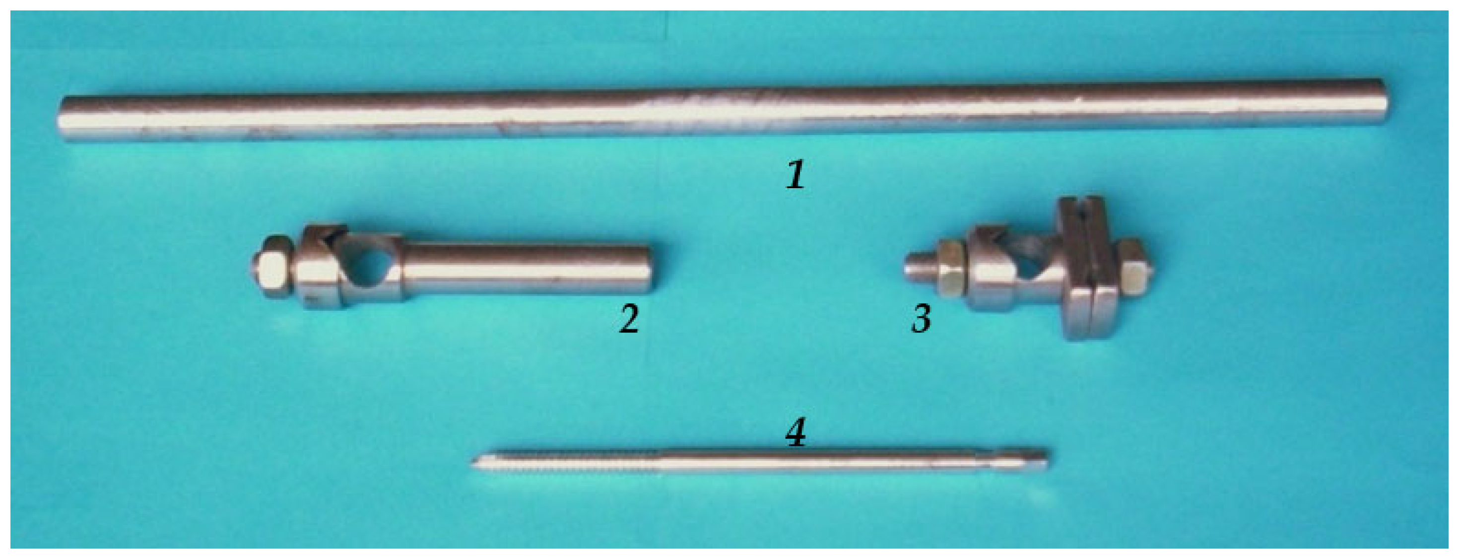
Figure 1. Components of the Sarafix external fixation system.
Applsci 15 12327 g001
Figure 2. Conceptual framework of the Sarafix external fixation system.
Applsci 15 12327 g002
Figure 3. The healing success rate of grade II and III open fractures treated with the Sarafix external fixator [38].
Applsci 15 12327 g003
Figure 4. Configuration A.
Applsci 15 12327 g004
Figure 5. Configuration B.
Applsci 15 12327 g005
Figure 6. Configuration C.
Applsci 15 12327 g006
Figure 7. Configuration D.
Applsci 15 12327 g007
Figure 8. Concept of axial loading test.
Applsci 15 12327 g008
Figure 9. Concept of four-point AP bending test.
Applsci 15 12327 g009
Figure 10. Concept of four-point ML bending test.
Applsci 15 12327 g010
Figure 11. Concept of torsion test.
Applsci 15 12327 g011
Figure 12. Wheatstone quarter-bridge with compensating strain gauge.
Applsci 15 12327 g012
Figure 13. Setup for axial compression loading test.
Applsci 15 12327 g013
Figure 14. Experimental setup for AP bending test of the C50 configuration.
Applsci 15 12327 g014
Figure 15. Experimental setup for ML bending test of the B50 configuration.
Applsci 15 12327 g015
Figure 16. Experimental setup for torsional testing of the D50 configuration.
Applsci 15 12327 g016
Figure 17. Axial load–displacement diagrams for fixator configurations with interfragmentary gaps of 20 mm (a) and 50 mm (b).
Applsci 15 12327 g017
Figure 18. Relationship between principal stresses and axial load for interfragmentary gaps of 20 mm (a) and 50 mm (b).
Applsci 15 12327 g018
Figure 19. Load–deflection diagrams for fixator configurations under AP bending, with interfragmentary gaps of 20 mm (a) and 50 mm (b).
Applsci 15 12327 g019
Figure 20. Variation of principal stress values under AP bending (configuration B50).
Applsci 15 12327 g020
Figure 21. Load–deflection diagrams for fixator configurations under ML bending, with interfragmentary gaps of 20 mm (a) and 50 mm (b).
Applsci 15 12327 g021
Figure 22. Variation of principal stress values in the case of ML bending (configuration B50).
Applsci 15 12327 g022
Figure 23. Torque–angular displacement diagrams for fixator configurations, with interfragmentary gaps of 20 mm (a) and 50 mm (b).
Applsci 15 12327 g023
Table 1. Tested Sarafix fixator configurations for tibial application.
ConfigurationTypeNumber of
Half-Pins
Number of ClampsNumber of Clamp Holders
A50Unilateral uniplanar44
A20
B50Unilateral uniplanar84
B20
C50Unilateral biplanar6 + 2/45°62
C20
D50Unilateral biplanar8 + 2/45°62
D20
Table 2. ANOVA—Displacement.
Sum of SquaresdfMean SquareFpη2η2pω2
Configuration86.3712.335.84<0.0010.0880.0880.073
Residuals897.14252.11
Table 3. Post Hoc Comparisons: Configurations subjected to axial compression.
Comparison
Configuration ConfigurationMean DifferenceSEdftptukey
A20-B200.78690.2944252.6780.132
-C200.71710.2944252.4400.225
-D200.89130.2774253.2170.030
-A50−0.49850.277425−1.8000.621
-B500.52650.2774251.9010.551
-C500.03940.2624250.1501.000
-D500.49090.2774251.7720.639
B20-C20−0.06980.310425−0.2251.000
-D200.10440.2944250.3551.000
-A50−1.28550.294425−4.375<0.001
-B50−0.26040.294425−0.8860.987
-C50−0.74750.280425−2.6740.133
-D50−0.29600.294425−1.0070.973
C20-D200.17410.2944250.5930.999
-A50−1.21570.294425−4.1370.001
-B50−0.19060.294425−0.6490.998
-C50−0.67780.280425−2.4250.232
-D50−0.22620.294425−0.7700.995
D20-A50−1.38980.277425−5.017<0.001
-B50−0.36470.277425−1.3160.892
-C50−0.85190.262425−3.2540.027
-D50−0.40040.277425−1.4450.836
A50-B501.02510.2774253.7000.006
-C500.53790.2624252.0550.446
-D500.98950.2774253.5710.009
B50-C50−0.48720.262425−1.8610.579
-D50−0.03560.277425−0.1291.000
C50-D500.45150.2624251.7250.671
Table 4. Results of axial compression testing of Sarafix fixator configurations.
ConfigurationMaximum Axial Displacement
δp, mm
Axial Stiffness
Cp, N/mm
Principal Stresses, MPa
σ1, SG+σ3, SG−
D504.08 (0.03)147.05325 (2.24)−380 (3.54)
D203.00 (0.09)200325 (2.83)−378 (3.96)
C504.35 (0.04)137.93330 (2.38)−375 (3.59)
C203.43 (0.02)174.93320 (2.15)−366 (3.18)
B504.04 (0.12)148.51334 (1.28)−374 (3.42)
B203.27 (0.04)183.49319 (1.26)−370 (2.50)
A506.69 (0.06)89.69326 (4.65)−379 (4.69)
A205.72 (0.12)104.9326 (2.89)−381 (3.87)
Note: The values in parentheses represent standard deviation.
Table 5. ANOVA—Deflection: Configuration subjected to AP bending.
Sum of SquaresdfMean SquareFpη2η2pω2
Configuration AP bending1.7570.2510.3880.9090.0070.007−0.011
Residuals240.063720.645
Table 6. Test results of Sarafix fixator configurations under AP bending.
ConfigurationMax. Deflection in the AP Plane
δAP, mm
AP Bending Stiffness
CAP, N/mm
Principal Stresses, MPa
σ1, SG+σ3, SG−
D502.36211.86269−274
D202.38210.08268−272
C502.54196.85268−271
C202.59193.05267−272
B502.48201.61263−269
B202.35212.77264−270
A502.81177.94262−265
A202.77180.51260−264
Table 7. ANOVA—Deflection Configuration subjected to ML bending.
Sum of SquaresdfMean SquareFpη2η2pω2
Configuration ML bending14.262.370.5070.8030.0100.010−0.010
Residuals1370.32934.68
Table 8. Results of testing Sarafix fixator configurations under ML bending.
ConfigurationMax. Deflection in the ML Plane
δML, mm
AP Bending Stiffness
CML, N/mm
Principal Stresses, MPa
σ1, SG+σ3, SG−
D506.7074.63278−282
D206.0582.65276−280
C506.9871.63283−286
C206.1880.91280−284
B507.2169.35292−297
B206.3878.37290−295
A507.6865.10292−297
A207.3568.03291−296
Table 9. ANOVA—Angular displacement.
Sum of SquaresdfMean SquareFpη2η2pω2
Configuration Torsion47.976.84118.5<0.0010.3230.3230.305
Residuals100.42720.369
Table 10. Post Hoc Comparisons: Configurations subjected to torque.
Comparison
Configuration ConfigurationMean DifferenceSEdftptukey
A20-B200.450860.1452723.103770.043
-C200.936960.1452726.45012<0.001
-D200.938230.1452726.45892<0.001
-A50−0.149350.145272−1.028140.970
-B500.461870.1452723.179550.035
-C500.922640.1452726.35155<0.001
-D500.896550.1452726.17195<0.001
B20-C200.486100.1452723.346360.021
-D200.487380.1452723.355150.020
-A50−0.600210.145272−4.131910.001
-B500.011010.1452720.075781.000
-C500.471780.1452723.247780.028
-D500.445690.1452723.068180.048
C20-D200.001280.1452720.008791.000
-A50−1.086310.145272−7.47827<0.001
-B50−0.475090.145272−3.270580.026
-C50−0.014320.145272−0.098571.000
-D50−0.040410.145272−0.278171.000
D20-A50−1.087580.145272−7.48706<0.001
-B50−0.476370.145272−3.279370.026
-C50−0.015600.145272−0.107371.000
-D50−0.041690.145272−0.286961.000
A50-B500.611220.1452724.20769<0.001
-C501.071990.1452727.37969<0.001
-D501.045900.1452727.20009<0.001
B50-C500.460770.1452723.172000.036
-D500.434680.1452722.992410.060
C50-D50−0.026090.145272−0.179601.000
Table 11. Results of testing Sarafix fixator configurations under torque.
ConfigurationMax. Angular Displacement
θ, °
Torsional Stiffness
CT, Nm/°
D503.83.95
D202.785.40
C504.363.44
C203.893.86
B505.882.55
B205.582.69
A508.581.75
A207.422.02
Table 12. Comparative stiffness values of different external fixators.
Stiffness/FixatorMeyrueis’s (One Rod)Noor’s
(One Rod)
Hoffmann 3
(One Rod)
Orthofix Modul
System
Dynafix (EBI)Sarafix
C20
Axial (N/mm)48.971.835261340174.93
AP bending
(N/mm)
--31220230193
ML bending
(N/mm)
4.44.76.5-6280.91
Torsional
(Nm/deg)
1.81.61.03-3.23.86
Disclaimer/Publisher’s Note: The statements, opinions and data contained in all publications are solely those of the individual author(s) and contributor(s) and not of MDPI and/or the editor(s). MDPI and/or the editor(s) disclaim responsibility for any injury to people or property resulting from any ideas, methods, instructions or products referred to in the content.