Article

Finite Element Simulation Analyses of Load-Bearing Capacity of RPP Material-Based Shoe Box

1
College of Marine Equipment and Mechanical Engineering, Jimei University, Xiamen 361021, China
2
Tongda Smart Tech (Xiamen) Co., Ltd., Xiamen 361027, China
*
Author to whom correspondence should be addressed.
Appl. Sci. 2025, 15(22), 12314; https://doi.org/10.3390/app152212314
Submission received: 3 November 2025 / Revised: 16 November 2025 / Accepted: 18 November 2025 / Published: 20 November 2025
(This article belongs to the Section Applied Industrial Technologies)

Abstract

The shoe box plays a significant role in daily life. Traditional shoe boxes have problems with poor moisture resistance and unclear load-bearing capacity. In this study, recycled polypropylene (RPP) was used as the shoe box material, and its mechanical properties were analyzed through a combination of experiments and finite element simulations to determine its load-bearing capacity. Firstly, the structure of the shoe box was designed, and experiments were conducted on the RPP shoe box to determine the load-bearing failure range. Secondly, the finite element software ANSYS WORKBENCH 2023 R1 was used to evaluate the load-bearing capacity of the shoe box in open and closed states. Finally, the results obtained from the simulation were analyzed. The failure range of the open state obtained by simulations is 13.5–15.5 kg, which is consistent with the experimental results (13.2–15.4 kg), and both results exhibited lower buckle failure: the maximum stress and strain both occur at the lower buckle. At 14.5 kg, the maximum stress is 29.67 MPa, exceeding the flexural strength, and the strain is 0.025, exceeding the fracture elongation, which meets the failure conditions. This study provides theoretical and technical support for the lightweight and high-load-bearing design of RPP shoe boxes.

1. Introduction

The shoe box is an important item for storing shoes as a daily household item. It cannot only effectively protect shoes from physical damage such as extrusion, friction, and collision during transportation, storage, or display, but also isolate external moisture and dust to keep shoes clean and dry, thereby extending the service life of shoes. Additionally, it can prevent the fading and aging of shoe upper materials caused by ultraviolet rays. The shoe box is also an important carrier of a brand; through a unique design, logos, colors, and text, it can convey the brand’s concept and culture. For example, the design of high-end shoe boxes can enhance the product’s grade and added value, attracting consumers to purchase them.
At present, the main materials of shoe boxes are corrugated cardboard and cardboard, which are popular due to their low cost, easy processing, and good environmental friendliness. However, they have shortcomings with poor moisture resistance and a low load-bearing capacity. With the increasing demand from consumers for environmental protection and a high-end experience, recycled materials, plastics, fabrics, and bio-based materials have also been gradually adopted. In contrast, recycled polypropylene (RPP) shoe boxes exhibit remarkable advantages: they offer superior moisture resistance, a higher load-bearing capacity, and excellent recyclability. Unlike cardboard that degrades under repeated loads, RPP maintains its structural integrity even after multiple usage cycles, making it a more durable and sustainable alternative for footwear packaging. Notably, footwear packaging is governed by specific standards such as the Chinese national standard GB/T 36975-2018 (General Technical Requirements for Footwear) [1] and international regulations, which mandate performance criteria for load bearing, material sustainability, and dimensional stability.
Recycled polypropylene (RPP) packaging, owing to its recyclability and performance advantages, resonates with the rising consumer demand for eco-conscious products and is gradually emerging as a preferred solution for high-end footwear packaging [2]. RPP is mainly derived from daily miscellaneous materials, bottle cap materials, ton bag materials, washing machine materials, automotive interior materials, cable materials, etc. The diversity of its sources leads to significant performance differences, and its overall performance is slightly inferior to that of virgin polypropylene (PP). However, its remarkable environmental value and resource recycling potential have promoted in-depth research on related modification and application. Studies have shown that waste RPP can be ultrafined into micro-scale powder using solid-phase shear milling technology, and synergistically combined with nano-silica to construct a superhydrophobic coating. This technology not only realizes the high-value utilization of recycled plastics but also endows the material with moisture-proof and self-cleaning properties [3]. As the core forming method for RPP products, injection molding process parameters have a significant impact on material performance. In hot runner injection molding, the melt temperature dominates the transformation from β crystals to α crystals, thereby affecting the mechanical stability of the products [4]. In terms of reinforcement modification, post-industrial recycled glass fibers can be used as the reinforcing phase of RPP, effectively improving its structural strength while ensuring material recyclability, providing a feasible path for material development oriented to a circular economy [5]. The addition of recycled short, milled carbon fibers also exhibits excellent reinforcement effects. When the fiber content is 5 wt%, the tensile modulus of RPP composites can be increased by 47.3% [6]. As a natural reinforcing agent, date palm microfibers can significantly improve the Shore-D hardness and tensile strength of RPP at a dosage of 10 wt%, providing new ideas for the construction of bio-based composite systems [7]. It is worth noting that RPP is often blended with other recycled plastics in practical applications, and the compatibility and thermal stability of the blending system are key research directions. Studies have found that when the mass ratio of recycled polyethylene (rPE) to RPP is 6:4, the thermodynamic properties and interfacial bonding state of the blend reach the optimal level [8]. In terms of molding process optimization, the application of in-mold rheological automatic control technology can control the mechanical property fluctuation of RPP injection-molded products within 5%, providing technical support for the consistency of mass production [9]. In addition, improving the solubility of RPP through partial oxidation modification can realize the large-scale preparation of superhydrophobic coatings, expanding the functional application scenarios of materials while practicing the concept of environmental protection [10]. In studies on the modification and application of RPP, diversified reinforcement strategies and functionalization technologies continue to expand its application boundaries: RPP nanocomposites reinforced with graphene nanoplatelets (GNPs) perform prominently. When the GNP addition reaches 20 Phr, the tensile strength increases by 15.6 MPa, and the thermal stability and electrical conductivity are significantly improved, providing a new path for the high-performance development of RPP [11]. Using tannic acid/stearic acid synergistically modified calcium carbonate as a filler can increase the tensile strength of RPP composites from 27.44 MPa to 30.53 MPa and simultaneously optimize toughness and thermal stability. This modification scheme has both environmental and cost advantages [12]. Research on the milling machinability of RPP wood–plastic composites shows that by optimizing milling parameters (such as spindle speed 600 rpm, feed rate 0.2 mm/rev), processing efficiency and surface quality can be significantly improved, laying a process foundation for its large-scale application in construction and other fields [13]. In the field of functionalization, RPP composite foam combined with metal powder can achieve electromagnetic shielding function, and the shielding efficiency is increased by 10–20% in the X-band, showing application potential in fields such as electronic packaging [14]. The bionanocomposite prepared by RPP and date palm nanofiller performs excellently in 3D printing. The tensile strength can reach 25.5 MPa at 3 wt% nanofiller content, providing a reference for the development of sustainable materials in the field of additive manufacturing [15]. Post-consumer RPP can be successfully spun into multifilament yarns after purification, with a tensile strength of 4.2 cN/dtex, breaking the traditional limitations of recycled plastics in high-value textile applications [16]. Surface-modified RPP fibers can also significantly enhance the anti-aging performance of asphalt, with the carbonyl content reduced by about 50%. The modification idea opens up a new direction for the cross-field engineering application of RPP [17].
In terms of the application expansion of finite element analysis (FEA), it demonstrates powerful analytical capabilities in multiple disciplines: In the field of structural mechanics, it can be used to study the bending and buckling behavior of porous beams reinforced with functionally graded carbon nanotubes [18], and can also realize the refined mechanical response analysis of helical wire ropes under multi-axial dynamic loads [19]. In composite material engineering, it is suitable for both the fatigue performance evaluation of adhesive joints in wind turbine blades [20] and the optimization of the mechanical properties of perforated prestressed concrete frames combined with artificial neural networks [21]. In the biomedical field, FEA can explore the influence of mandibular kinematics on dental structures [22], assist in the optimization of bionic nail treatment schemes for osteoporotic femoral fractures [23], and even be used for the biomechanical evaluation of the diameter of subperiosteal implant screws [24]. In terms of engineering design and optimization, FEA can support the fatigue life prediction of excavator turntables [25], the response surface method optimization of electromagnetic forming process parameters [26], and the accuracy verification of wind turbine bearings [27]. Meanwhile, the development of open-source MATLAB solvers [28], the macro-scale simulation of bainite transformation on the flow behavior of steel [29], the frequency domain finite element analysis of beam structure cracks [30], and even the visualization of FEA results through augmented reality to assist in the evaluation of clamping concepts [31] all reflect the broad potential of FEA in method innovation and cross-field applications.
However, existing studies mostly focus on the macro-mechanical property characterization of RPP composites, and there is still a lack of research on the stress distribution and failure mechanism of RPP structural parts (such as shoe boxes) under actual opening, closing, and load-bearing conditions. To overcome this problem, this study uses RPP as the shoe box material. Through a combination of experimental tests and finite element simulations, it analyzes the load-bearing failure range of the shoe box in open and closed states, simulates the stress and deformation laws of key parts, verifies the consistency between simulation and experimental results, and provides data support for the engineering application of RPP in shoe boxes and similar packaging structural parts. However, this study has limitations regarding its experiments and finite element simulations, such as the lack of long-term testing and the adoption of linear–elastic approximation. These limitations, however, do not diminish the significance of this study. Instead, they point to potential avenues for future research, while the current work still offers valuable insights into the short-term load-bearing performance of RPP shoe boxes.
The remaining structure of this paper is as follows. Section 2 introduces the specific properties of the RPP material, the shoe box structure, the failure test methods of the shoe box, and the applied finite element formulas. Section 3 presents the settings of the finite element software. Section 4 draws the results, and the Section 5 draws the conclusions.

2. Materials and Methods

2.1. Material Properties

The basic physical properties of the RPP material used for the shoe box in this study are shown in Table 1.

2.2. Structural Model

The shoe box consists of three parts, an outer shell, an inner liner, and a handle, with a total mass of 2.2 kg. Figure 1 shows the 2D diagram of the shoe box, where Figure 1a is the front view and Figure 1b is the side view. In Figure 1, L is the total length of the shoe box, H is the total height of the shoe box, W is the total width of the shoe box, and A is the maximum opening angle of the shoe box. Stiffeners are located at the upper and lower buckle locations of the inner liner and outer shell, and a filet design is applied to the transition positions of the outer shell. Specific values and tolerances of key parts are listed in Table 2. Figure 2 shows the 3D diagram of the shoe box, where Figure 2a is the closed state of the shoe box and Figure 2b is the open state of the shoe box. To clarify how the geometric parameters (L, W, H, A) translate into boundary conditions and contacts in the finite element model, we define the model as follows: L (total length of the shoe box) determines the longitudinal dimension. We constrain the longitudinal displacement at the bottom end of the outer shell as a boundary condition. W (total width) defines the lateral dimension, with no displacement constraint in this direction to simulate free movement. H (total height) represents the vertical dimension, and the top end of the inner liner is free of constraints. Angle A is set by configuring the revolute joint.
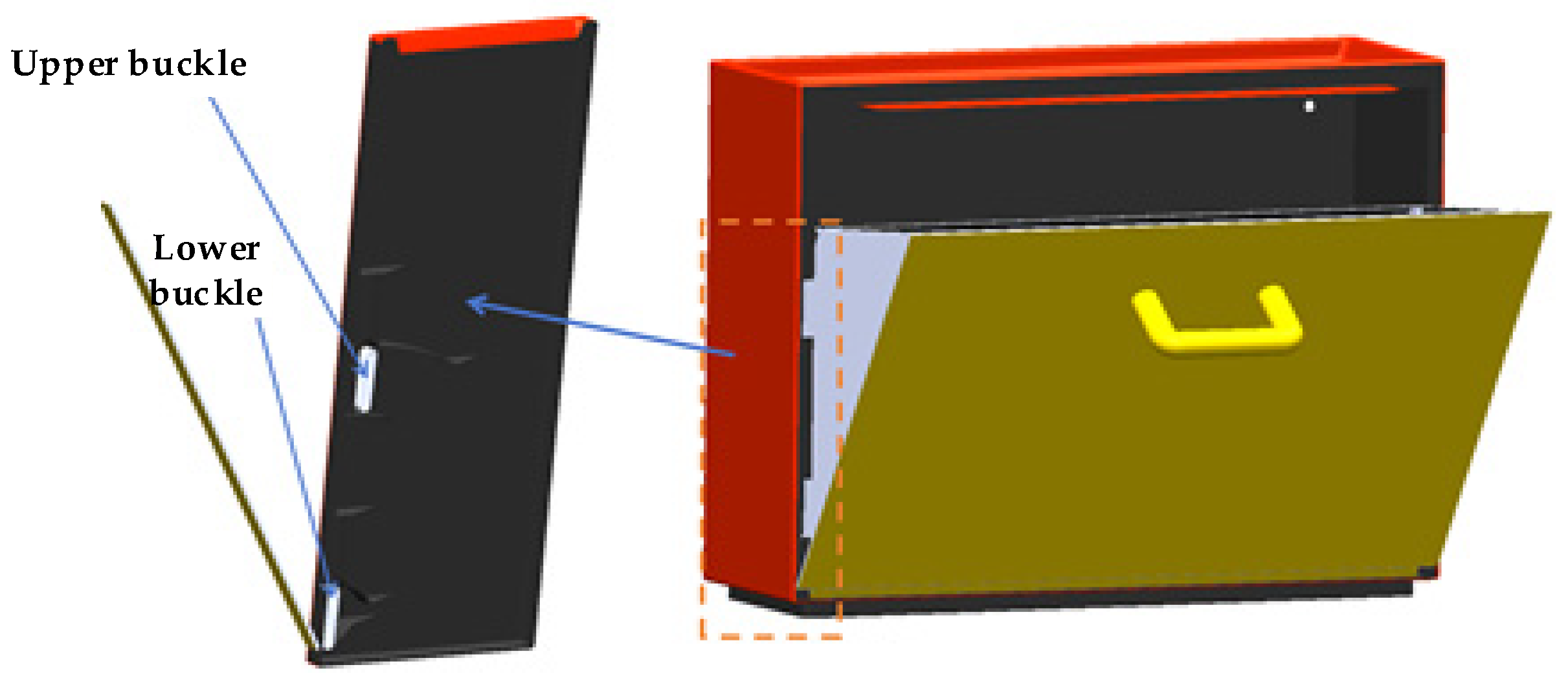
Figure 3 shows the internal working principle of the shoe box, where the upper buckle and the lower buckle (including the rotating shaft) are fixed on the side of the box. The structural diagrams of the upper buckle and the lower buckle are shown in Figure 4. The inner liner is opened and closed through the two lower buckles of the outer shell. When the shoe box is opened, the weight of the shoes is borne by the two upper buckles and two lower buckles. There are four bolt holes on the back of the outer shell of the shoe box for installation, enabling wall-mounted installation. The inclined surface of the inner liner is used for placing shoes.

2.3. Experimental Overview

2.3.1. Experimental Purpose

In the closed state, the key parts bear much less force compared with the open state, so we only consider the experimental analysis of the open state. We determine the load-bearing failure range of the RPP shoe box in the open state (according to the material property table, the flexural strength of the RPP material used for the shoe box is 28 MPa and the fracture elongation is 0.02) and clarify the load-bearing mass range when the shoe box fractures. Through multi-dimensional observations and repeated verification, the reliability and consistency of the experimental results are ensured.

2.3.2. Experimental Setup and Conditions

Experimental samples: 2 RPP shoe boxes of the same batch (named as S1 and S2), with no obvious scratches, dents, or other initial damage to the appearance; the material uniformity meets the production standards verified by the manufacturer. Load carrier: 2.2 kg standard A4 cartons (size: 297 mm × 210 mm × 150 mm, made of corrugated cardboard); the mass of each carton is calibrated with an electronic scale to ensure the mass deviation of a single carton is ≤±0.02 kg. These cartons are used to simulate the equivalent load of the shoe mass.
Experimental environment: The laboratory temperature is controlled at 25 ± 2 °C, and the relative humidity is 50 ± 5%. This is to avoid additional impacts of temperature and humidity fluctuations on the mechanical properties of RPP.
Auxiliary tools: A high-definition digital camera (used to record the deformation and fracture characteristics of the shoe box during the loading process) and a steel ruler (accuracy: 1 mm, used to measure the deformation).

2.3.3. Experimental Procedures

The “stepwise static loading + real-time observation” method was adopted, with the specific process as follows:
Initial state calibration: Place the shoe box on a horizontal and stable experimental platform in the open state. Use a digital camera to take photos of the initial appearance of the key parts of the shoe box, which serves as the reference for deformation comparison.
Graded loading: Place the 2.2 kg A4 cartons on the load-bearing area of the inner liner of the shoe box one by one in a stable manner. After loading each carton, let it stand for 30 s, and then observe the structural changes in the shoe box.
State recording: After each loading, record whether the shoe box has “irreversible deformation” or “fracture” through visual observation and digital camera shooting. For suspected deformation, use a steel ruler to measure the size of the key parts to quantify the deformation degree. To ensure reproducibility and statistical confidence, each sample (S1 and S2) was subjected to five tests.

2.3.4. Experimental Results

Loading process of sample S1 (0–13.2 kg): When loaded to the 3rd carton (6.6 kg), slight sagging was observed in the load-bearing area of the inner liner with the naked eye, but it could fully rebound after the load was removed. When loaded to the 6th carton, there was no obvious gap at the joint between the upper and lower buckles and the outer shell, and no cracks or fractures were found in any parts; the shoe box could still bear the load stably. Load of 15.4 kg (7 cartons): At the moment of loading the 7th carton, fracture occurred at the connection between the lower buckle and the inner liner. After the fracture, the inner liner lost its load-bearing capacity, and the cartons slipped off.
Repeat verification of sample S2: To verify the repeatability of the experimental results, the same loading process was carried out on sample S2. When loaded with the 6th carton, there was no irreversible damage; when loaded with the 7th carton, fracture also occurred at the connection between the lower buckle and the inner liner, and the fracture position and morphology were highly consistent with those of sample S1.
After each test, the sample was allowed to stand for a short interval before conducting the next test, and three more tests were performed following the same procedure (resulting in a total of five tests per sample).
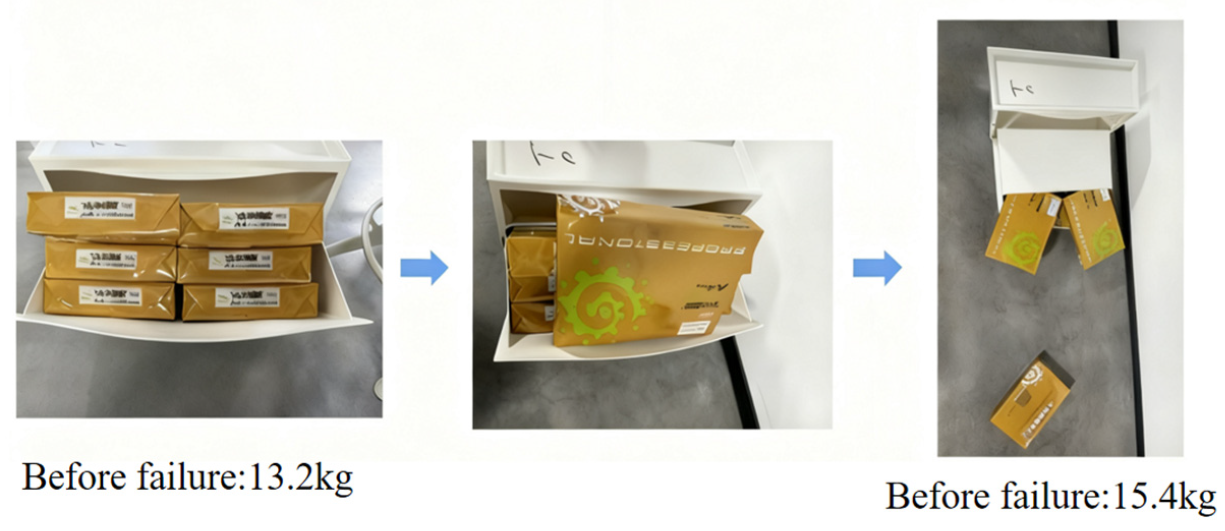
Through the experimental verification of two samples from the same batch (with a total of ten experiments conducted), it was found that, on average, when the load-bearing mass of the inner liner is in the range of 13.2–15.4 kg in the open state, the structure of the RPP shoe box fractures and fails, which is in agreement with the results obtained from the subsequent finite element method (FEM). Moreover, the fracture positions are consistent, all being at the connection between the lower buckle and the inner liner, indicating that this part is the “mechanical weak point” of the shoe box’s load bearing. In the subsequent finite element simulation, the stress distribution and failure mechanism of this part will be focused on, and the load-bearing performance in the closed state will be verified. Figure 5 shows the experimental process.

2.4. Finite Element Modeling

To accurately simulate the mechanical response of the RPP shoe box under load-bearing conditions, it is necessary to rely on the core theories of elastic mechanics and finite element methods to establish a quantitative relationship between “material–structure–load”. This section expounds the theoretical basis of the subsequent simulation analysis from three aspects, the basic equations of elastic mechanics, the stress–strain constitutive relation, and the finite element discretization principle, providing support for the establishment of the shoe box model and the interpretation of results.

2.4.1. Basic Equations of Elastic Mechanics

Under the assumptions of small deformation and linear elasticity, the mechanical behavior of a continuous medium must satisfy three core equations, an equilibrium equation, a geometric equation, and a constitutive equation, which together describe the field distribution laws of stress, strain, and displacement.
Equilibrium equation (motion equation): For a micro-element in 3D space, the balance between external forces and internal forces must satisfy the following partial differential Equation (1) when considering inertial forces:
σ x x x + τ y x y + τ z x z + F x = ρ 2 u t 2 τ x y x + σ y y y + τ z y z + F y = ρ 2 v t 2 τ x z x + τ y z y + σ z z z + F z = ρ 2 w t 2
σ x x , σ y y , σ z z are normal stress components; τ y x , τ z x , τ x y , τ z y , τ x z , τ y z are shear stress components; F x , F y , F z are volume force (such as gravity) components; ρ is material density; u , v , w are displacement components along the x , y , z directions; and t is time.
For the static load-bearing analysis of the shoe box, the inertial term ρ 2 u t 2 can be ignored, and the equation degrades to the static equilibrium equation, where external forces and internal forces are directly balanced.
Strain is the geometric derivative of the displacement field. The equations of normal strain and shear strain Equation (2) are as follows:
ε x x = u x ,       ε y y = v y ,       ε z z = w z ,       γ x y = u y + v x ,       γ y z = v z + w y ,       γ z x = w x + u z
In the equation, ε x x , ε y y , ε z z are normal strain components; γ x y , γ y z , γ z x are shear strain components. The geometric equation directly relates the “displacement field” and “strain field”, which is the core input condition for the subsequent constitutive equation.

2.4.2. Stress–Strain Constitutive Relation

The constitutive equation describes the physical response law of “stress–strain” of materials. For isotropic linear elastic materials (such as the mechanical behavior of RPP before yielding), it obeys Hooke’s law in a generalized form, and its matrix form is given as follows in Equation (3):
σ x x σ y y σ z z τ x y τ y z τ z x = E ( 1 + ν ) ( 1 2 ν ) 1 ν ν ν 0 0 0 ν 1 ν ν 0 0 0 ν ν 1 ν 0 0 0 0 0 0 1 2 ν 2 0 0 0 0 0 0 1 2 ν 2 0 0 0 0 0 0 1 2 ν 2 ε x x ε y y ε z z γ x y γ y z γ z x
Among them, E is the elastic modulus (tensile modulus), and ν is Poisson’s ratio. This equation relates the “strain field” and “stress field” and is the core basis for “material property assignment” in finite element simulation.

2.4.3. Finite Element Discretization Principle

(1)
Element Displacement Interpolation and Stiffness Matrix
For any element, the relationship between the node displacement vector { δ } e and the displacement { u } at any point in the element can be described by the shape function matrix as follows (Equation (4)):
{ u } = [ N ] { δ } e
Combining the geometric equation (strain–displacement relationship) and the constitutive equation (stress–strain relationship), the element stiffness matrix [ K ] e can be derived as follows (Equation (5)):
[ K ] e = V [ B ] T [ D ] [ B ] d V
In the equation, [ B ] is the strain–displacement matrix (obtained by differentiating the shape function [ N ] with respect to coordinates), [ D ] is the constitutive matrix (derived from the generalized Hooke’s law), and V is the element volume.
(2)
Assembly and Solution of the Overall Equation
Through “element assembly”, the stiffness matrices of all elements are integrated into the overall stiffness matrix [ K ] . Combined with the boundary conditions and the load vector { F } , the overall displacement equation is solved as follows (Equation (6)):
[ K ] { Δ } = { F }
where { Δ } is the overall node displacement vector. After obtaining the displacement, the strain and stress fields are back-calculated through the geometric equation and constitutive equation, realizing the full-process calculation from “displacement to stress and strain”.

2.4.4. Material Nonlinearity and Limitations of Linear–Elastic Approximation

The finite element framework in Section 2.4.1, Section 2.4.2 and Section 2.4.3 relies on linear–elastic assumptions (small deformations, linear stress–strain behavior), which are retained as the basis for subsequent calculations. However, RPP (a polymer) exhibits inherent viscoelasticity, plasticity, and damage under loading phenomena not captured by linear elasticity, making it an approximate treatment.
For more realistic modeling of RPP, the following numerical models are being considered:
Viscoelastic models: The Maxwell model (spring–dashpot series) describes time-dependent deformation, with its 1D constitutive equation as follows (Equation (7)):
ε ˙ = σ ˙ E + σ η
where E = elastic modulus, η = viscosity, and σ ˙ / ε ˙ = stress/strain rates.
(1)
Bilinear plasticity model: Elastic up to yield stress σ y , then plastic deformation with tangent modulus E t . as follows (Equation (8)):
σ = E ε σ σ y σ y + E t ( ε ε y ) σ > σ y
Von Mises yield criterion is calculated as follows (Equation (9)):
σ eq = 3 2 s : s σ y
where ε y = σ y / E (yield strain), σ eq = equivalent stress, and s = deviatoric stress tensor.
(2)
Damage mechanics model: Quantifies microcrack evolution via scalar damage variable d (0 = undamaged, 1 = fully damaged) as follows (Equation (10)):
σ eff = σ 1 d
Damage evolution (Lemaitre’s model) is calculated as follows (Equation (11)):
d ˙ = ε ˙ p 1 d Y R n
where σ eff = effective stress, σ = nominal stress, ε ˙ p = plastic strain rate, Y = damage energy release rate, R = damage resistance, and n = material parameter.

3. Finite Element Software Settings

3.1. Analysis Purpose

The finite element software ANSYS WORKBENCH was used to simulate the deformation, stress, and critical failure mass of the RPP shoe box in the open state under different bearing masses. To more intuitively show the situation of the open state, the closed state was used as a control. For the simulation results, focus should be placed on parts such as the upper buckle and lower buckle, as they are the key parts for bearing mass. To facilitate simulation analysis, the non-essential handle component is omitted.

3.2. Establishment of the Simulation Model

When establishing the finite element model of the shoe box, since the shoe box has few components and a simple shape, there is no need to simplify the model. To determine the deformation and stress state of the open state under force, the SOLIDWORKS model of the shoe box in the open state was saved as an X_T format that can be opened by WORKBENCH. Before entering the simulation interface, the RPP material was set in advance. The static module was added to the main interface, and relevant parameters were set. The common unit system, i.e., millimeter (mm), kilogram (kg), and Newton (N), was used in the finite element solver. Therefore, the stress unit displayed in the contour diagram in the post-processing stage is megapascal (MPa).

3.2.1. Material Assignment

In the WORKBENCH interface, material properties were assigned to the materials to be simulated and analyzed. The material properties are shown in Table 1. Figure 6 shows the two states of the shoe box in the WORKBENCH interface, where Figure 6a is the closed state and Figure 6b is the open state.

3.2.2. Contact Setting: Closed State

There are 3 pairs of contacts between the outer shell and the inner liner. The 3 contacts are the 2 contacts between the lower buckles of the inner liner and the lower buckles of the outer shell, and the contact between the outer surface of the outer shell and the inner surface of the inner liner. The contacts are defined as no-separation contacts, because this type of contact is suitable for components that are in close contact but may have relative sliding, which is suitable for shoe box simulation. In the contact setting, the inner liner was set as the contact surface, and the outer shell was set as the target surface. The reason for this is that the outer shell needed to be observed finally and has high stiffness, so it is set as the target surface. To balance convergence and accuracy, the augmented Lagrangian method was used as the contact algorithm.
Open state: There are 4 pairs of contacts between the outer shell and the inner liner, which are the 2 contacts between the upper buckles of the inner liner and the upper buckles of the outer shell, and the 2 contacts between the lower buckles of the inner liner and the lower buckles of the outer shell. These 4 contacts are no-separation friction contacts. To prevent the inner liner from rotating and detaching from the outer shell under force, the inner liner was still set as the contact surface and the outer shell as the target surface in the contact setting.
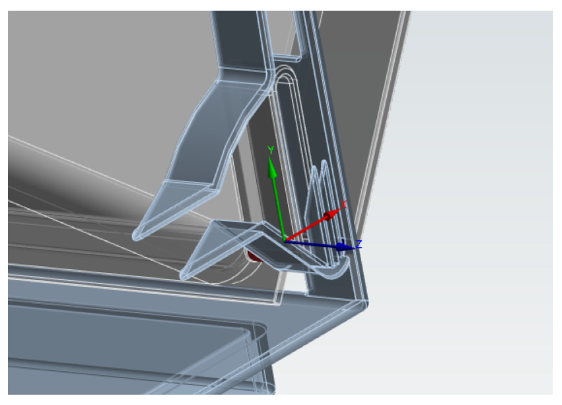
In addition to setting contacts, a revolute joint should also be set. The inner liner opens and closes around the lower end of the lower buckle of the outer shell. Therefore, a revolute joint in the connection pair was set at the lower end of the lower buckle. The characteristic of the revolute joint is that the two set parts rotate around the z-axis. For the specific setting of the revolute joint, the lower buckle of the outer shell was set as the reference, and the lower buckle of the inner liner was set as the moving part. Figure 7 shows the setting of the revolute joint.

3.2.3. Mesh Generation

To better control the mesh quality and more accurately obtain the stress between components, a local refinement method for special positions was adopted. Tetrahedral elements were used for mesh discretization of each component, and the elements were refined as regularly as possible. The basic mesh size of the outer shell is 8 mm, and that of the inner liner is 10 mm. The contact areas of the upper and lower buckles of the outer shell and inner liner (key parts) were refined, with a refinement size of 0.7 mm. Figure 8 shows the mesh generation of the closed shoe box. The total number of meshes is 181,585, and the number of nodes is 343,769.
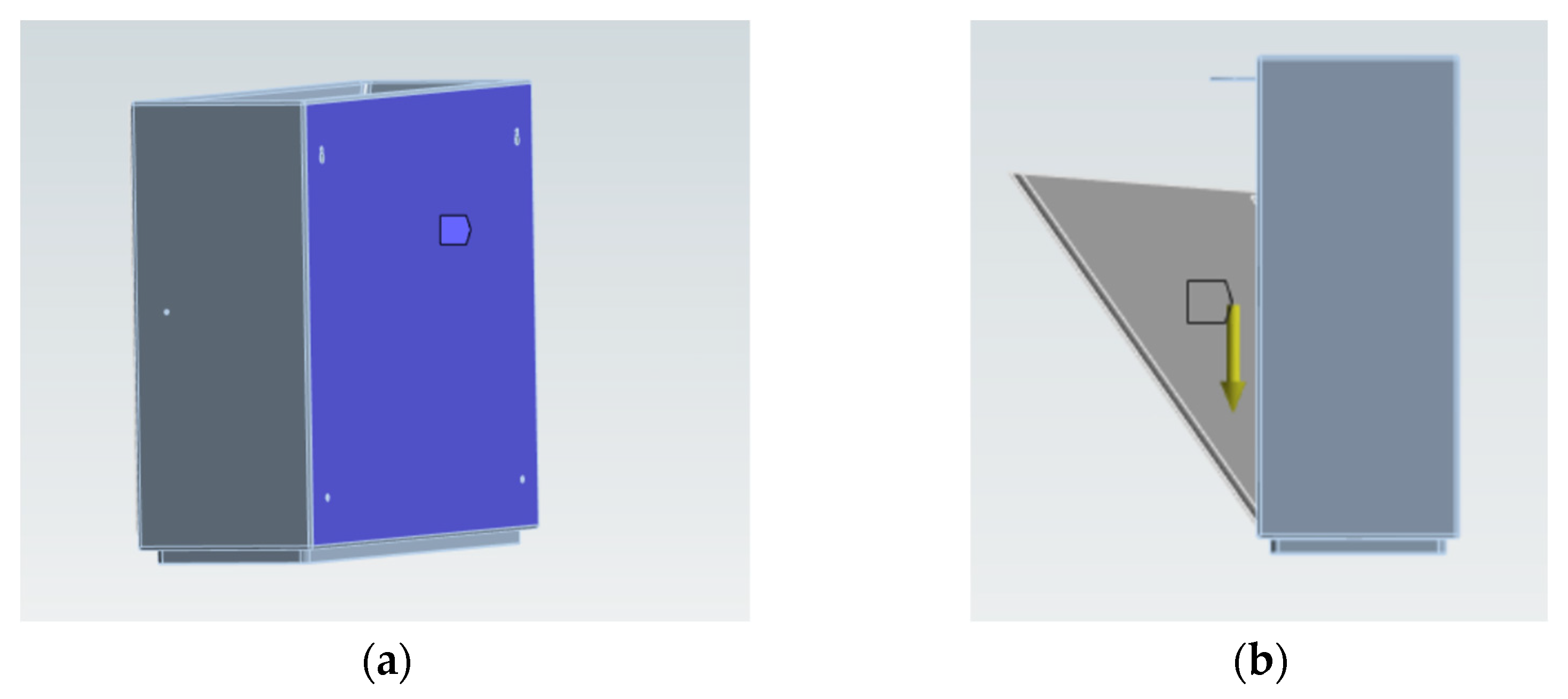
To accurately capture the interaction between components, their fitting dimensions were considered and the design gaps were retained. Boundary constraint conditions were set at the contact area between the right outer shell of the shoe box and the wall, and a downward standard Earth gravity constraint (9.8 m/s2) was applied. To fully consider the time response, the time step was set to 10 steps, and the time was 1 s. Figure 9 shows the constraint settings, where Figure 9a is the displacement constraint and Figure 9b is the gravity constraint.
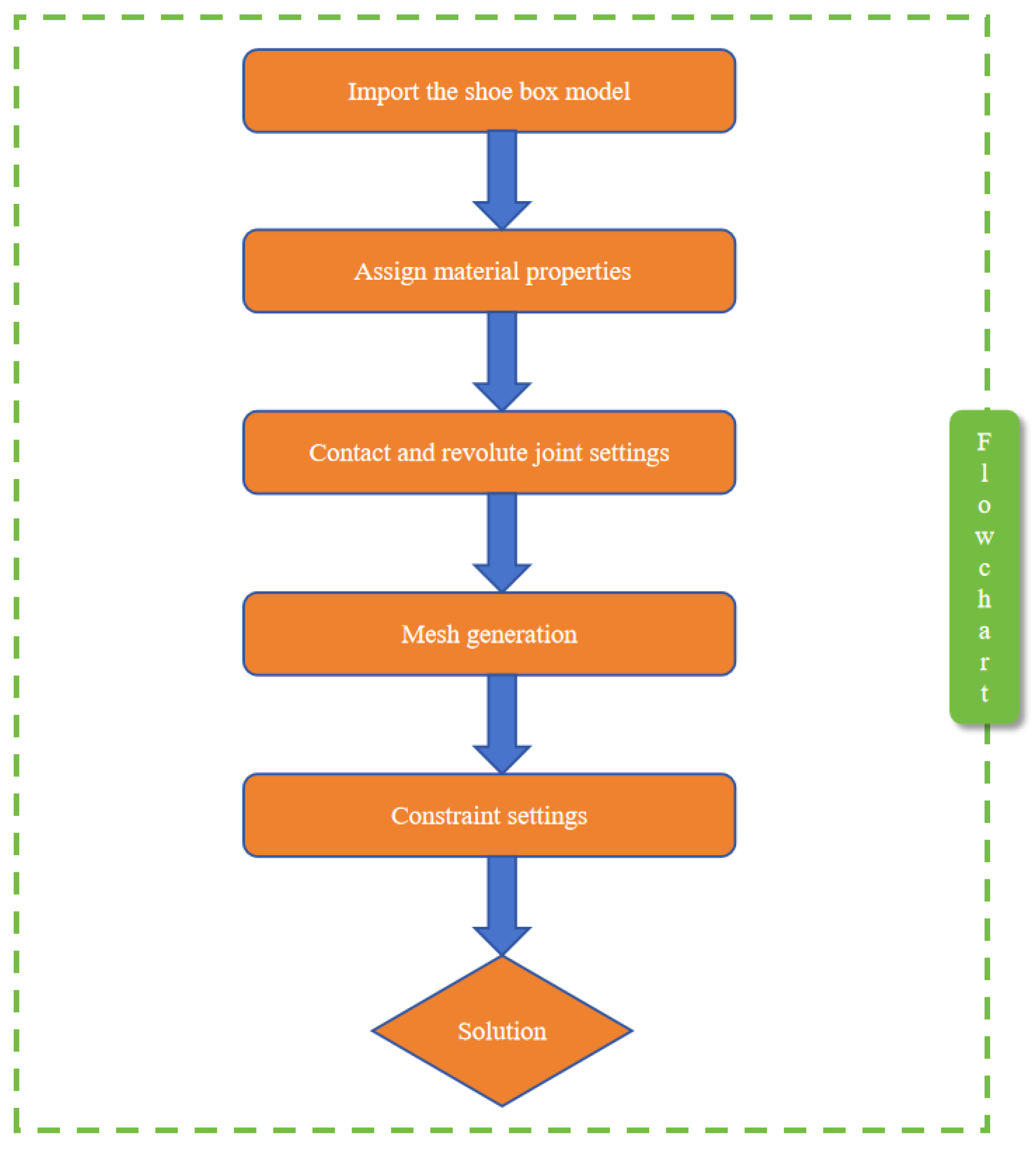
To reduce the impact of components and increase the calculation speed, the shoe mass was converted into a force load acting on the inner liner of the shoe box in this study. The direction is the same as that of gravity acceleration (vertically downward). For more accurate expression, the mass range from 11.5 kg to 16.5 kg was selected. The magnitudes of each force load are shown in Table 3. Based on all the above, Figure 10 shows the flow chart of the finite element software settings.

4. Results

4.1. Stress and Strain Responses Under Different Working States

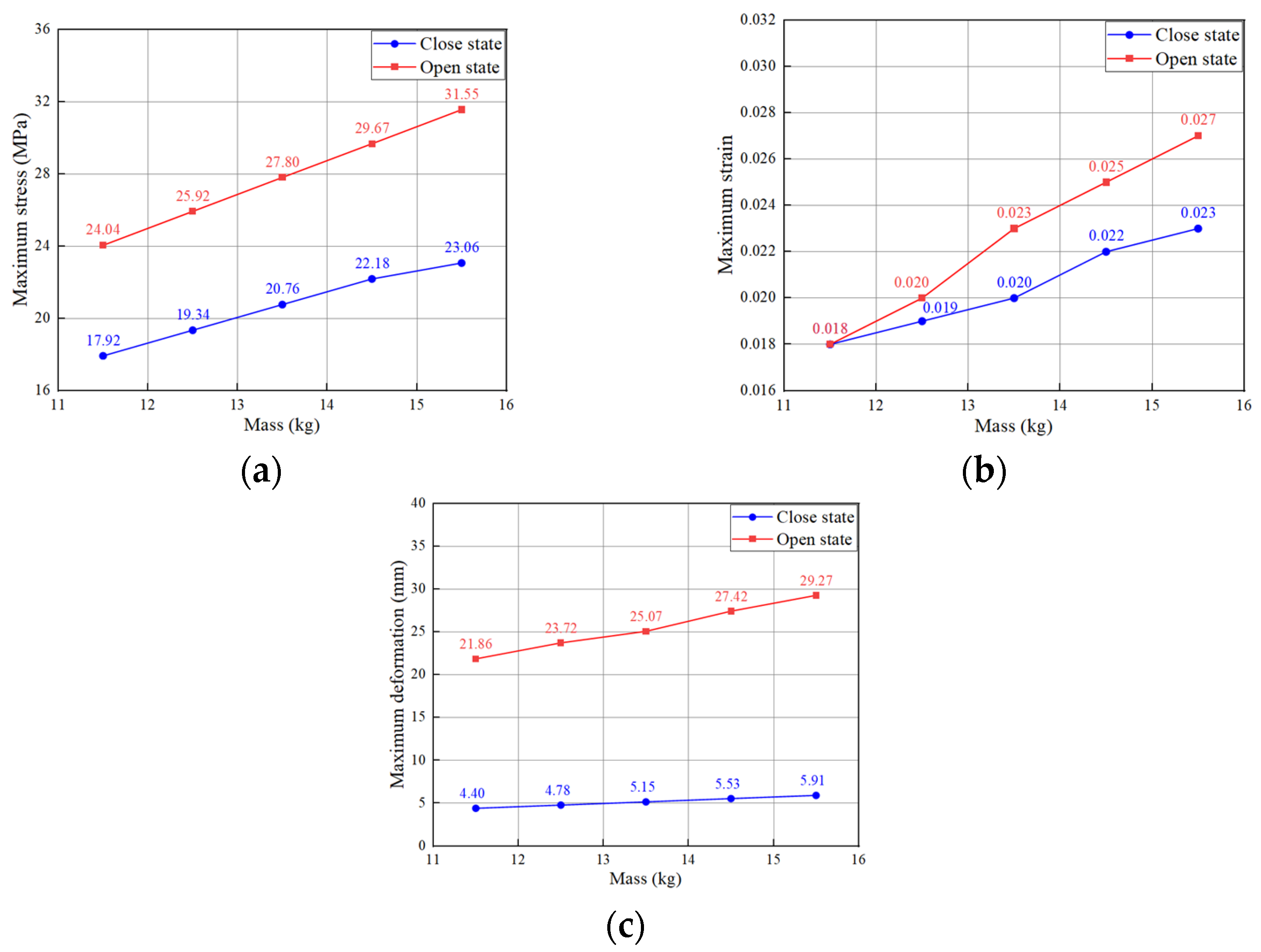
Figure 11 shows the line charts of maximum equivalent stress, maximum equivalent strain, and maximum deformation of the shoe box in the closed state and open state. Figure 11a is the line chart of maximum stress; Figure 11b is the line chart of maximum strain; and Figure 11c is the line chart of maximum deformation. The horizontal axis represents the applied force mass (which can also be converted into load), and the vertical axis represents each dependent variable. In general, under the two working states, the maximum stress, maximum strain, and maximum deformation all increase approximately linearly with the increase in mass. However, the mechanical response of the open state is more sensitive to the load, and the growth rates of stress and strain are significantly higher than those of the closed state. The specific characteristics are as follows:
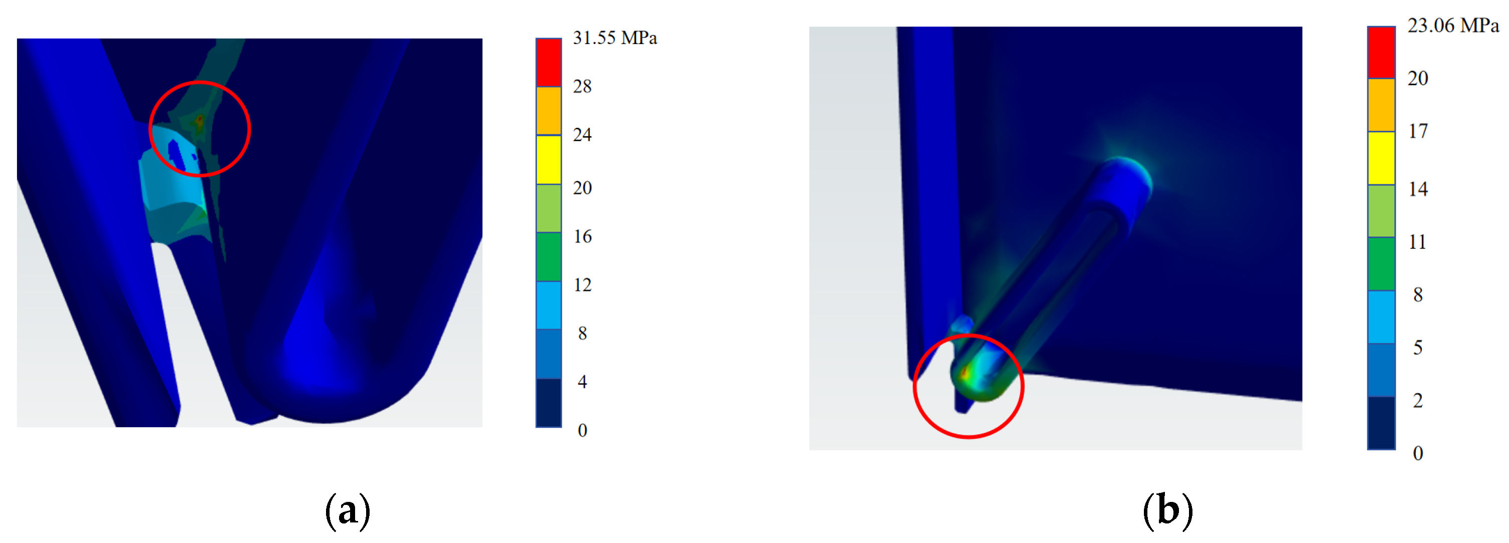
It is worth noting that the maximum stress and strain occur at the lower buckle regardless of the closed or open state. In the closed state, the maximum stress is always lower than the flexural strength of RPP; even when the mass reaches 15.5 kg, the maximum stress is only 23.06 MPa, still retaining a strength redundancy of about 17.6%. In the open state, the stress increases more significantly: when the load is 13.5 kg, the maximum stress reaches 27.80 MPa (close to the flexural strength); when the mass reached 14.5 kg, the stress rose to 29.67 MPa (exceeding the flexural strength); and when the mass reaches 15.5 kg, it further reaches 31.55 MPa.
Under the initial load of 11.5 kg, the maximum strains of the closed and open states are similar, indicating that the difference in structural stiffness between the two states is not significant at low loads. With the increase in mass, the strain growth rate of the open state is faster: when the mass is 13.5 kg, the maximum strain of the open state reaches 0.023 (exceeding the fracture elongation of RPP), while that of the closed state is only 0.020; when the mass increased to 15.5 kg, the maximum strain of the open state further rose to 0.027, and that of the closed state is 0.023. This trend indicates that the structural constraint of the shoe box is weaker in the open state (e.g., the interaction between the inner liner and the outer shell decreases), and the local load-bearing areas (such as the upper buckle and the rotating shaft of the lower buckle) are more prone to plastic deformation. In the closed state, the strain has exceeded the limit when the mass is 14.5 kg, but the stress does not reach the strength limit. This characteristic of “strain exceeding the limit first and stress reaching the limit later” is observed under the linear–elastic model. To avoid artifacts of this simplification, future work will adopt an elastic–plastic model (e.g., J2 model with isotropic hardening) and check against the Huber–Mises criterion to further verify the “stress–strain coupled triggering” mechanism of RPP fracture.
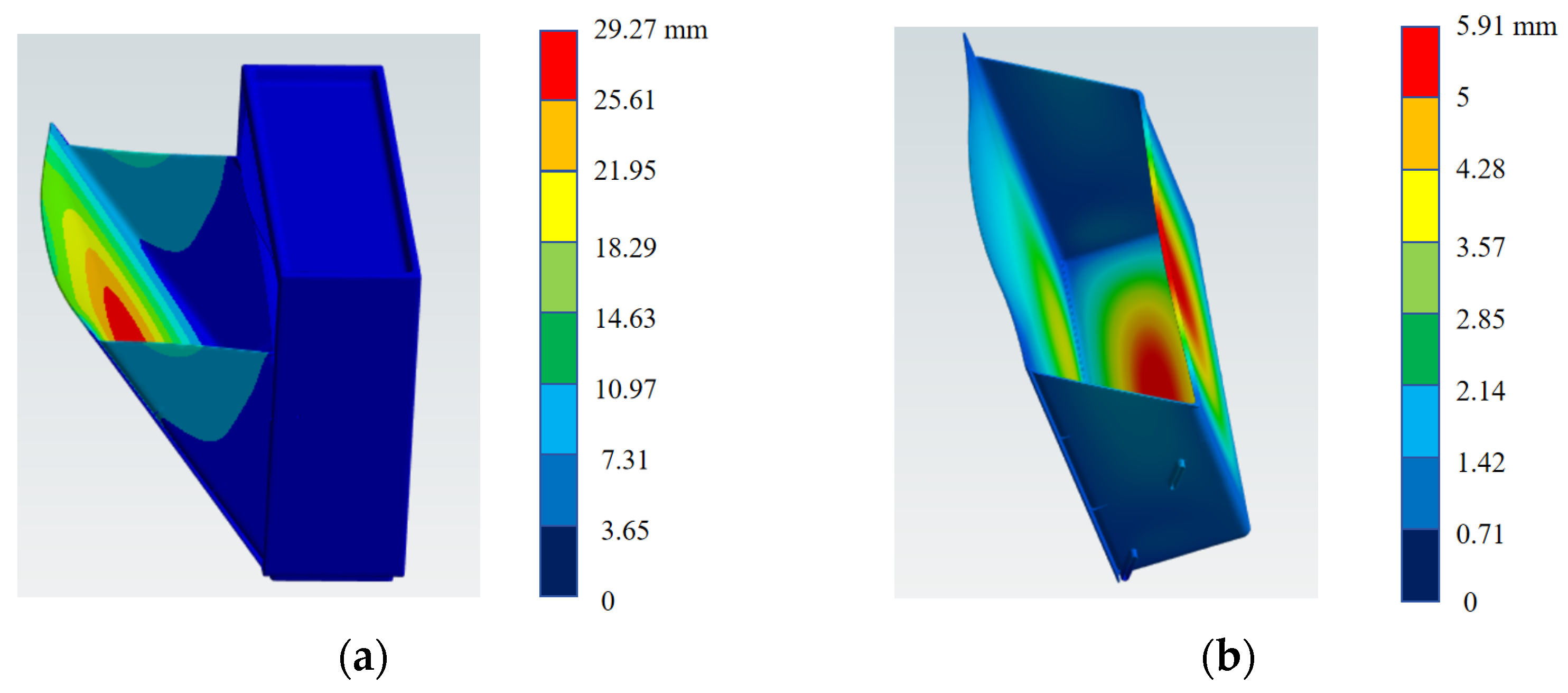
In the open state, the strain exceeds the fracture elongation and the stress approaches the flexural strength at 13.5 kg, indicating that the shoe box may fracture and fail. However, no fracture occurred at 13.5 kg in the experiment. The reason may be that the chemical bonds and molecular chain bonding forces of the material have not been damaged (i.e., the stress state), and the plastic deformation at this time is still in the “recoverable or stable development” stage, which has not reached the fracture threshold of “molecular chain fracture or interface debonding”. When the mass is 14.5 kg, both the stress and strain exceed the allowable values, indicating that fracture and failure will definitely occur. Figure 12 shows the contour diagrams of the maximum stress positions in the two states, where Figure 12a is the contour diagram of the maximum stress position in the open state and Figure 12b is the contour diagram of the maximum stress position in the closed state. Figure 13 shows the contour diagrams of the deformation positions in the two states, where Figure 13a is the contour diagram of the deformation position in the open state and Figure 13b is the contour diagram of the deformation position in the closed state. Regardless of the open or closed state, the maximum stress occurs at the rotating shaft of the lower buckle, indicating that the rotating shaft of the lower buckle is the first to fail, which is consistent with the experiment.

4.2. Mechanical Response Analysis of the Upper Buckle in the Open State

In addition to the lower buckle (analyzed in the previous subsection), the upper buckle is also a key part. Since the upper buckle does not bear the load when the shoe box is closed (only the lower buckle is in contact and bears the load), only the deformation, strain, and stress of the upper buckle in the open state need to be focused on. Figure 14 shows the line charts of the maximum stress, strain, and deformation of the upper buckle. Figure 14a is the line chart of the maximum stress of the upper buckle; Figure 14b is the line chart of the maximum strain of the upper buckle; and Figure 14c is the line chart of the maximum deformation of the upper buckle. Although the maximum stress of the upper buckle increases continuously with the increase in mass, it is always lower than the flexural strength of RPP: at 13.5 kg, the stress is 21.22 MPa (with a strength redundancy of about 24.2%); at 15.5 kg, the stress rises to 25.78 MPa (with a strength redundancy of about 8.0%). The strain of the upper buckle has the same variation trend as the stress with the increase in mass, but the “criticality” of the strain growth is more prominent than that of the stress: at 13.5 kg, the strain reaches 0.020, which is equal to the fracture elongation of RPP; at 15.5 kg, the strain further rises to 0.023, exceeding the fracture elongation. This indicates that when the load is ≥13.5 kg, the “plastic deformation degree” of the local material of the upper buckle has reached the “strain critical condition for fracture”. It can be seen from the deformation curve that the maximum deformation of the upper buckle increases continuously and linearly with the increase in mass: the deformation is 1.80 mm at 11.5 kg, increases to 2.10 mm at 13.5 kg, and reaches 2.40 mm at 15.5 kg. Since the strain exceeds the fracture elongation, this deformation is plastic deformation, and the macro-geometric integrity of the structure will gradually degrade with the increase in load.
Under the load of 15.5 kg, the strain of the upper buckle exceeds the limit, but the stress does not reach the strength limit. This characteristic of “strain exceeding the limit first and stress reaching the limit later” further reflects that the fracture of RPP is a process of “stress–strain coupled triggering”. Therefore, the upper buckle in the current state has the risk of “excessive plastic deformation”, but no immediate fracture occurs. Figure 15 shows the stress distribution and deformation state contour diagrams of the upper buckle, where Figure 15a is the stress of the upper buckle and Figure 15b is the deformation of the upper buckle. The stress on the lower part is greater than that on the upper part, and the deformation degree increases from the lower right to the upper left. The reason may be that the stress and deformation near the inner liner are larger.

4.3. Mechanical Response of the Outer Shell Surface in Closed and Open States

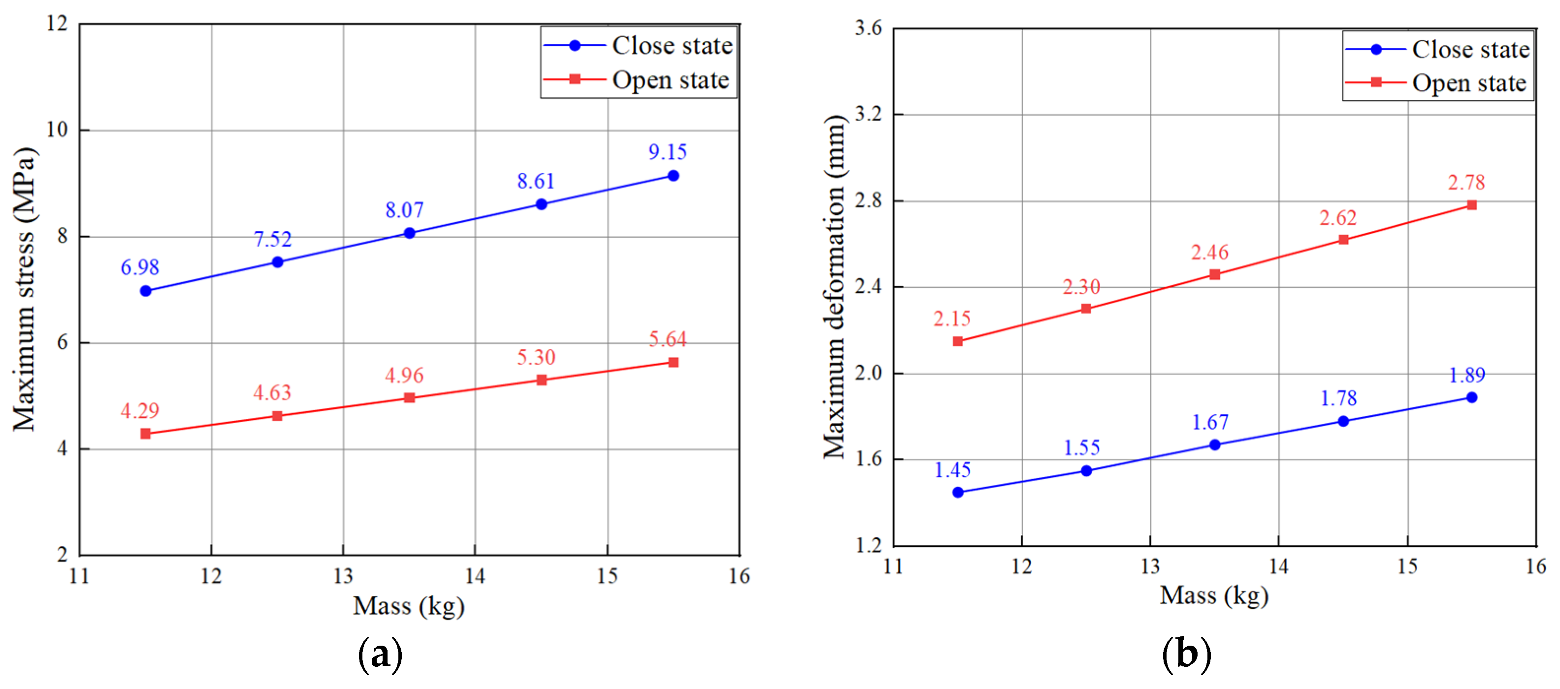
Figure 16 shows the line charts of the maximum stress and maximum deformation of the contact area between the outer shell and the inner liner (the outer shell surface) of the shoe box in the closed mode and open mode. Figure 16a is the line chart of the maximum stress of the contact part; Figure 16b is the line chart of the maximum deformation of the contact part. Combining the structural characteristics of the two working states (the outer shell is in close contact with the inner liner in the closed state, and there is no contact in the open state), the differences in the load-bearing and deformation behaviors of the outer shell can be analyzed.
It can be seen from the maximum stress curve that the stress in the closed mode is significantly higher than that in the open mode: at 11.5 kg, the stress in the closed mode is 6.98 MPa, which is 1.62 times that in the open mode; at 15.5 kg, the stress in the closed mode is 9.15 MPa, which is still 1.62 times that in the open mode. This difference is due to the “contact synergy effect” between the outer shell and the inner liner. In the closed state, the load is transmitted through the contact interface between the inner liner and the outer shell, and the outer shell needs to bear the load together with the inner liner, so the stress is more concentrated. In the open state, the contact surface of the outer shell lacks direct load transmission from the inner liner and only needs to bear the indirect load of its own area, so the stress level is lower. The maximum deformation curve shows the opposite trend: the deformation growth rate of the open mode is much higher than that of the closed mode. This is because in the closed state, the inner liner forms a “rigid support” for the outer shell, limiting the plastic deformation of the outer shell. In the open state, the outer shell loses the support of the inner liner, resulting in a decrease in structural stiffness and a higher tendency to deform under the same load, which is reflected in the mechanical response of “low stress but large deformation”.
The comparison between the two modes shows that the “contact cooperation between the outer shell and the inner liner” is a key factor affecting the mechanical properties of the shoe box.
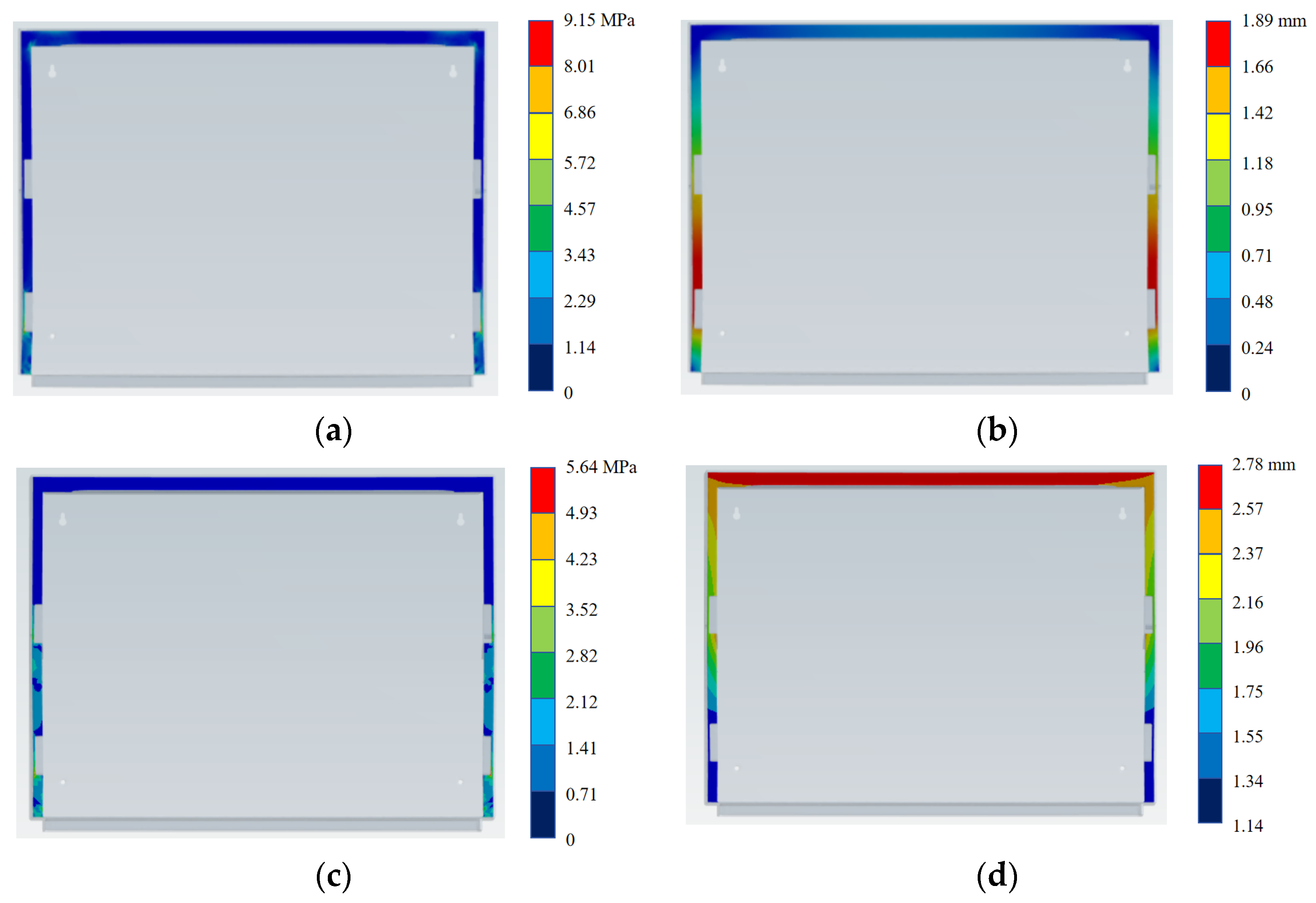
The “contact cooperative load bearing” in the closed state increases the stress of the outer shell but effectively controls the deformation through “inner liner support”, ensuring the overall stiffness of the structure. The “non-contact state” in the open state reduces the stress of the outer shell but increases the risk of excessive deformation due to a “lack of support”. Figure 17 shows the contour diagrams of the stress and deformation states of the contact part in the two states, where Figure 17a is the stress contour diagram of the contact part in the closed state; Figure 17b is the deformation contour diagram of the contact part in the closed state; Figure 17c is the stress contour diagram of the contact part in the open state; and Figure 17d is the deformation contour diagram of the contact part in the open state. It can be seen that the stress concentration in the closed state is distributed at the lower buckle, while the stress concentration in the open state is distributed at the upper and lower buckles and the area between them. The deformation in the closed state is concentrated in the middle of the upper and lower buckles, which will make the middle of the shoe box bulge, while the deformation in the open state is concentrated at the upper part.

5. Conclusions

This study systematically analyzed the load-bearing characteristics, stress–strain deformation responses, and failure mechanism of an RPP shoe box under different working states using a combination of experimental tests and finite element simulations, and drew the following conclusions:
(1)
The experimental results of the load-bearing limit of the shoe box show that the failure load in the open state is 13.2–15.4 kg, which is manifested as the fracture of the lower buckle and the slipping of the inner liner. In the finite element simulation, when the load reaches 13.5 kg, the stress of the lower buckle is close to the flexural strength of RPP, and the local strain exceeds the fracture elongation. The possible reasons for the slight discrepancies between the experimental results and the finite element results are as follows:
(i)
Load resolution: Differences in how the load is incremented between experimental tests and numerical simulations.
(ii)
Weighing error: Inherent variability in experimental weight measurements.
(iii)
Contact conditions: Variations in friction, contact area, or component fit between physical tests and finite element models.
(2)
The flexural strength and fracture elongation of RPP are the core parameters for judging the fracture of the shoe box. When the local strain exceeds the fracture elongation but the stress does not reach the flexural strength, the material does not fracture immediately due to “excessive plastic deformation but remaining strength redundancy”, but there is a risk of “delayed fracture”. When the stress reaches the flexural strength and the strain exceeds the limit, “stress–strain coupled fracture” is triggered, which is the main failure mode of the shoe box in the open state.
(3)
Closed state: Due to the “contact cooperative load bearing between the outer shell and the inner liner”, the stress distribution is more uniform, the deformation is limited by the support of the inner liner, the overall load-bearing capacity is stronger, and there is no risk of local strain exceeding the limit. Open state: After losing the support of the inner liner, the lower buckle becomes a “stress-dominated high-risk fracture part”, and both the upper and lower buckles are “strain-dominated potential deformation parts”, so the overall mechanical performance is significantly weaker than that in the closed state.
(4)
Based on the research results, the structural optimization of the shoe box can focus on two directions: For the open state, strengthen the “stress fracture resistance” design of the lower buckle and optimize the “strain deformation resistance” design of both the upper and lower buckles. For the closed state, utilize the “contact synergy effect between the outer shell and the inner liner” and improve the overall load-bearing efficiency by optimizing the contact part between the inner liner and the outer shell.
This study clarifies the material properties, structural characteristics, and simulation analysis of an RPP shoe box and provides theoretical and technical support for the lightweight and high-load-bearing design of recycled polypropylene packaging products.

Author Contributions

Conceptualization, Y.T. and J.F.; methodology, H.Z.; software, J.L.; validation, J.L.; formal analysis, J.F.; investigation, H.Z.; resources, J.L.; data curation, H.Z.; writing—original draft preparation, Y.T.; writing—review and editing, J.F. and J.L.; visualization, Y.T.; supervision, Y.T.; project administration, Y.T.; funding acquisition, J.F. All authors have read and agreed to the published version of the manuscript.

Funding

This research was supported by the National Natural Science Foundation of China (grant number: 42506217), Fujian Provincial Natural Science Youth Funding (grant number: 2024J08195), Fujian Provincial Natural Science General Funding (grant number: 2023J01791), the Xiamen City Department of Science and Technology (grant number: 3502Z202471046), and the Fujian Provincial Department of Education (grant number: JZ230027).

Institutional Review Board Statement

Not applicable.

Informed Consent Statement

Not applicable.

Data Availability Statement

Data will be made available upon request.

Conflicts of Interest

Author Jie Luo was employed by the company Tongda Smart Tech (Xiamen) Co., Ltd. The remaining authors declare that the research was conducted in the absence of any commercial or financial relationships that could be construed as a potential conflict of interest.

References

  1. GB/T 36975-2018; General Technical Requirements for Footwear. Standards Press of China: Beijing, China, 2018.
  2. Beghetto, V.; Sole, R.; Buranello, C.; Al-Abkal, M.; Facchin, M. Recent Advancements in Plastic Packaging Recycling: A Mini-Review. Materials 2021, 14, 4782. [Google Scholar] [CrossRef] [PubMed]
  3. Wang, X.T.; Liang, Y.F.; Pu, Z.C.; He, J.; Yang, S.Q. Transforming waste to treasure: Superhydrophobic coatings from recycled polypropylene for high-value application. Prog. Org. Coat. 2024, 188, 108248. [Google Scholar] [CrossRef]
  4. Bowen, N.; Guyer, C.; Rippon, T.; Daly, M.; Gao, P.; Galati, V.; Lograsso, S.; Johnston, S.; Masato, D. Mechanical and crystallization properties of hot runner injection molded virgin and recycled polypropylene. Polym. Eng. Sci. 2024, 64, 2241–2255. [Google Scholar] [CrossRef]
  5. Shahroodi, Z.; Krempl, N.; Zidar, D.; Mayrhofer, T.; Kirschnick, U.; Arbeiter, F.; Duretek, I.; Holzer, C. Waste-to-Value Feasibility Study: Assessing the Viability and Quality of Incorporating Different Postindustrial Glass-Fiber Composites into Postconsumer Recycled Polypropylene. ACS Sustain. Chem. Eng. 2024, 12, 12619–12631. [Google Scholar] [CrossRef]
  6. Zheng, Y.T.; Gu, F.; Wang, B.; Wang, Z.; Gao, C.; Zhou, Y.; Hall, P. Thermal and mechanical behaviour of recycled short milled carbon fibre reinforced polypropylene and recycled polypropylene composites: A comparative study. J. Mater. Res. Technol. 2024, 32, 4221–4233. [Google Scholar] [CrossRef]
  7. Albedah, A.; Abdo, H.S.; Mohammed, S.; Bouiadjra, B.A.B.; Al-Ghurabi, E.H.; Alothman, O.Y. Potential of recycled polypropylene: A study on effect of natural fiber on the morphology and properties of biocomposite. J. King Saud Univ. Sci. 2024, 36, 103167. [Google Scholar] [CrossRef]
  8. Zhang, W.C.; Shen, J.; Guo, X.G.; Wang, K.; Jia, J.; Zhao, J.T.; Zhang, J.S. Comprehensive Investigation into the Impact of Degradation of Recycled Polyethylene and Recycled Polypropylene on the Thermo-Mechanical Characteristics and Thermal Stability of Blends. Molecules 2024, 29, 4499. [Google Scholar] [CrossRef]
  9. Krantz, J.; Nieduzak, Z.; Licata, J.; O’Meara, S.; Gao, P.; Masato, D. In-mold rheology and automated process control for injection molding of recycled polypropylene. Polym. Eng. Sci. 2024, 64, 4112–4127. [Google Scholar] [CrossRef]
  10. Li, X.K.; Wang, J.Q.; Chan, S.P.; Teong, S.P.; Zhang, Y.G. Scalable superhydrophobic coatings with recycled polypropylene. Green Chem. 2024, 26, 4493–4497. [Google Scholar] [CrossRef]
  11. Dananjaya, V.; Abeykoon, C. Thermo-mechanical and electrical properties of graphene nanoplatelets reinforced recycled polypropylene nanocomposites. Int. J. Lightweight Mater. Manuf. 2025, 8, 374–384. [Google Scholar] [CrossRef]
  12. Yu, C.H.; Ye, L.D.; Li, D.C.; Liu, H.B.; Wei, Q.Y.; Huang, Y.Y.; Wu, Z.J.; Zhang, L.L.; Li, Z.W.; Lu, S.R. Synergistic effect of tannic acid/stearic acid/calcium carbonate/recycled polypropylene polymer composites and molecular dynamics simulation study. Polym. Compos. 2025, 46, 9134–9147. [Google Scholar] [CrossRef]
  13. Teklemuz, T.G.; Gerezgiher, A.G.; Tesfay, A.G. Enhancing the machinability of recycled polypropylene composites reinforced with waste cotton and pine sawdust through milling parameters optimization. J. Thermoplast. Compos. Mater. 2025, 38, 4122–4140. [Google Scholar] [CrossRef]
  14. Marrocco, V.; Surace, R.; Brandonisio, E.; Marasco, I.; Pagano, C.; Tonetti, C.; Errico, V.; Calò, G.; Campanelli, S.L.; Fassi, I. Investigating EMI shielding performance of recycled polypropylene (PP) composite foams with reused metal powders. Mater. Des. 2025, 254, 114106. [Google Scholar] [CrossRef]
  15. Alzebdeh, K.; Alsafy, M.; Al-Kindi, K.; Al-Anqoodi, A.; Al-Alawi, A.; Al-Hinai, N. Optimization and Characterization of Recycled Polypropylene and Date Palm Nanocomposites for 3D Printing Applications. J. Mater. Eng. Perform. 2025, 34, 24073–24089. [Google Scholar] [CrossRef]
  16. Frankenbach, L.A.; Lukoschek, S.; Kruppke, I.; Cherif, C. Multifilament spinning of mechanically recycled polypropylene from post-consumer sources for a circular economy in textile applications. Sci. Rep. 2025, 15, 14047. [Google Scholar] [CrossRef] [PubMed]
  17. Chen, S.; Cao, Y.M.; He, X.Y.; Su, Y.; Wang, Y.J.; Wang, W.T.; Yang, C.; Jin, Z.H.; Fan, M.; Liu, Z.H.; et al. Preparation and ageing resistance enhancement of RP/SBS composite asphalt by heterostructure copper oxalate nanoparticles/recycled polypropylene fiber. Constr. Build. Mater. 2025, 473, 140992. [Google Scholar] [CrossRef]
  18. Belabed, Z.; Tounsi, A.; Bousahla, A.A.; Tounsi, A.; Khedher, K.M.; Salem, M.A. Mechanical behavior analysis of FG-CNTRC porous beams resting on Winkler and Pasternak elastic foundations: A finite element approach. Comput. Concr. 2024, 34, 447–476. [Google Scholar] [CrossRef]
  19. Li, H.L.; Yan, H. Refined finite element analysis of helical wire ropes under multi-axial dynamic loading. Adv. Eng. Softw. 2025, 200, 103823. [Google Scholar] [CrossRef]
  20. Liu, Z.; Liang, J.L.; He, Z.F.; Liu, X.; Liu, H.D.; Shao, Z.J. A developed fatigue analysis approach for composite wind turbine blade adhesive joints using finite-element submodeling technique. Eng. Fail. Anal. 2024, 164, 108701. [Google Scholar] [CrossRef]
  21. Wu, Y.C.; Chen, J.B.; Zhu, P.; Zhi, P. Finite Element Analysis of Perforated Prestressed Concrete Frame Enhanced by Artificial Neural Networks. Buildings 2024, 14, 3215. [Google Scholar] [CrossRef]
  22. Özcan, C.; Lestriez, P.; Özcan, M.; Josset, Y. Finite element analysis of dental structures: The role of mandibular kinematics and model complexity. Front. Dent. Med. 2024, 5, 1461909. [Google Scholar] [CrossRef]
  23. Shen, X.; Guo, H.; Chen, G.X.; Lian, H.Y.; Guo, W.; Wang, Z.; Xu, Z.H.; Li, Z.T. Finite element analysis of proximal femur bionic nail for treating intertrochanteric fractures in osteoporotic bone. Comput. Methods Biomech. Biomed. Eng. 2025, 28, 1991–2002. [Google Scholar] [CrossRef] [PubMed]
  24. Kundakcioglu, A.; Gedik, B. Comparison of Screws with Different Diameters in Subperiosteal Implant Application with Finite Element Analysis. Int. J. Med. Sci. 2024, 21, 2595–2602. [Google Scholar] [CrossRef] [PubMed]
  25. Xian, C.; Zhang, H.; Kim, Y.C.; Zhang, H.; Liu, Y. Programmed system for fatigue life prediction of excavator turntables based on multi-body dynamics and finite element analysis. Heliyon 2024, 10, e33126. [Google Scholar] [CrossRef] [PubMed]
  26. Satonkar, N.; Venkatachalam, G.; Pitchumani, S.V. Finite Element Analysis of Electromagnetic Forming Process and Optimization of Process Parameters Using RSM. Mathematics 2024, 12, 1622. [Google Scholar] [CrossRef]
  27. Kim, S.W.; Song, J.W.; Hong, J.P.; Kim, H.J.; Kang, J.H. Finite Element Analysis and Validation of Wind Turbine Bearings. Energies 2024, 17, 692. [Google Scholar] [CrossRef]
  28. Wang, B.; Bai, J.T.; Lu, S.B.; Zuo, W.J. An open source MATLAB solver for contact finite element analysis. Adv. Eng. Softw. 2025, 199, 103798. [Google Scholar] [CrossRef]
  29. Faraji, T.; Irani, M.; Korpala, G.; Ostwald, C.; Hatscher, A.; Prahl, U. Modeling the influence of bainite transformation on the flow behavior of steel using a macroscale finite element analysis. Int. J. Plast. 2025, 184, 104189. [Google Scholar] [CrossRef]
  30. Sahu, O.; Das, P.; Muni, M.K.; Pradhan, N.; Basa, B.; Sahu, S.K. Frequency-Based Crack Effect Study on Beams Under Free Vibration Using Finite Element Analysis. Eng. Trans. 2024, 72, 95–114. [Google Scholar] [CrossRef]
  31. Maier, W.; Möhring, H.C.; Feng, Q.; Wunderle, R. Augmented reality to visualize a finite element analysis for assessing clamping concepts. Int. J. Adv. Manuf. Technol. 2024, 133, 2293–2302. [Google Scholar] [CrossRef]
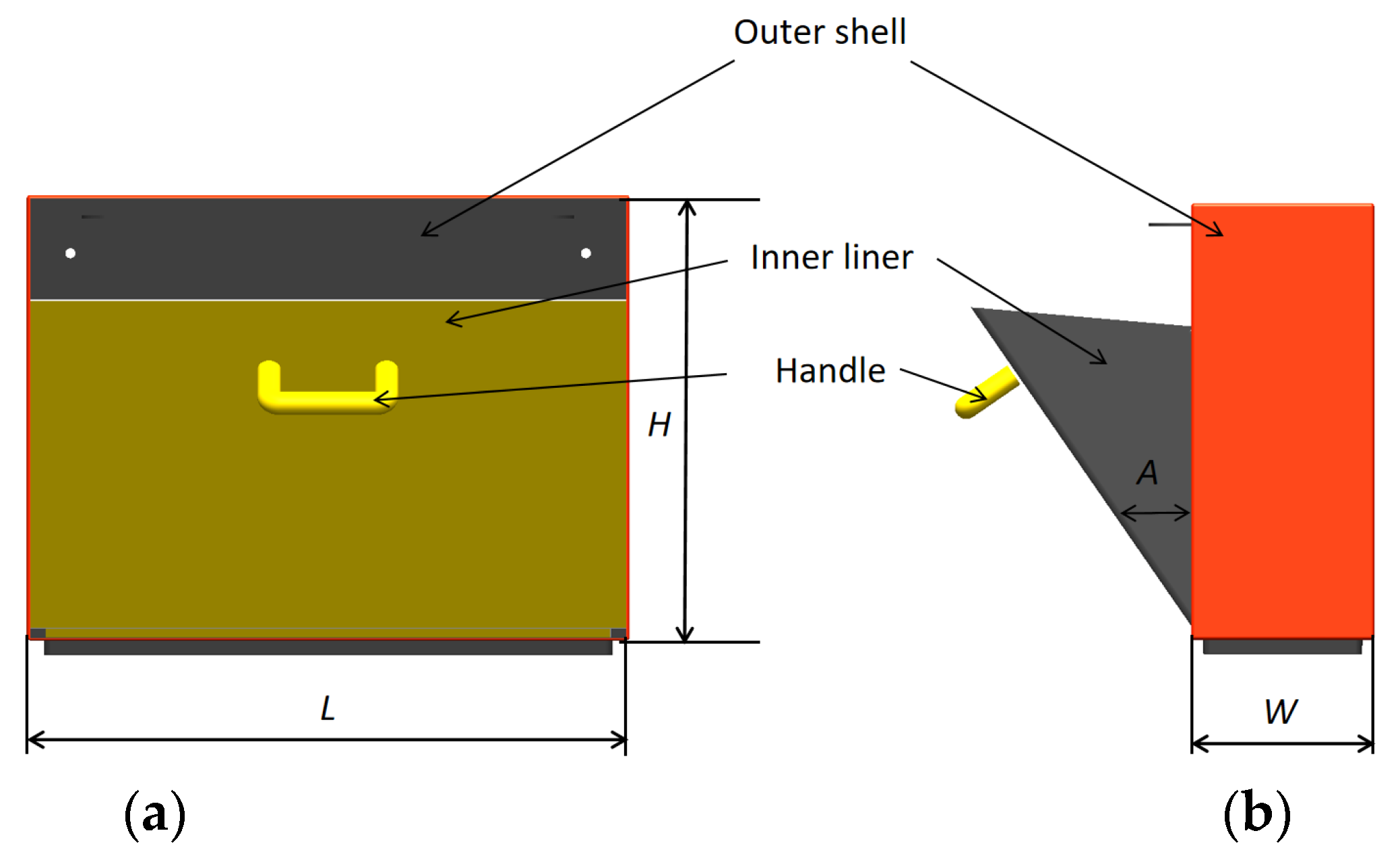
Figure 1. The 2D structural design of the RPP shoe box: (a) front view, (b) side view.
Applsci 15 12314 g001
Figure 2. The 3D schematic diagram of the RPP shoe box: (a) closed state of the shoe box, (b) open state of the shoe box.
Applsci 15 12314 g002
Figure 3. Internal view of the shoe box.
Applsci 15 12314 g003
Figure 4. Structural diagrams of the buckles: (a) upper buckle, (b) lower buckle.
Applsci 15 12314 g004
Figure 5. Schematic diagram of the experimental process.
Applsci 15 12314 g005
Figure 6. Two states of the shoe box in the WORKBENCH interface: (a) closed state, (b) open state.
Applsci 15 12314 g006
Figure 7. Setting of the revolute joint.
Applsci 15 12314 g007
Figure 8. Mesh generation of the closed shoe box.
Applsci 15 12314 g008
Figure 9. Constraint settings: (a) displacement constraint, (b) gravity constraint.
Applsci 15 12314 g009
Figure 10. Flow chart.
Applsci 15 12314 g010
Figure 11. Line charts of maximum stress, strain, and deformation in the two states: (a) maximum stress, (b) maximum strain, (c) maximum deformation.
Applsci 15 12314 g011
Figure 12. Contour diagrams of maximum stress in the two states: (a) maximum stress in open state (marked with a red circle), (b) maximum stress in closed state (marked with a red circle).
Applsci 15 12314 g012
Figure 13. Contour diagrams of deformation in the two states: (a) deformation in open state, (b) deformation in closed state.
Applsci 15 12314 g013
Figure 14. Line charts of maximum stress, strain, and deformation of the upper buckle: (a) maximum stress of the upper buckle, (b) maximum strain of the upper buckle, (c) maximum deformation of the upper buckle.
Applsci 15 12314 g014
Figure 15. Stress distribution and deformation distribution contour diagrams of the upper buckle in the open state: (a) stress of the upper buckle, (b) deformation of the upper buckle.
Applsci 15 12314 g015
Figure 16. Line charts of maximum stress and maximum deformation of the contact part between the outer shell and the inner liner: (a) maximum stress of the contact part, (b) maximum deformation of the contact part.
Applsci 15 12314 g016
Figure 17. Contour diagrams of stress and deformation of the contact part: (a) stress of the contact part in closed state, (b) deformation of the contact part in closed state, (c) stress of the contact part in open state, (d) deformation of the contact part in open state.
Applsci 15 12314 g017
Table 1. Physical properties of RPP material.
Name/UnitValue
Elastic modulus/MPa1250
Density/(kg/m3)950
Poisson’s ratio0.4
Flexural strength (MPa)28
Fracture elongation0.02
Table 2. Specific values and tolerances of key parts.
ParameterSymbolValueTolerance
Total length of the shoe boxL513 mm±1 mm
Total width of the shoe boxW159 mm±1 mm
Total height of the shoe boxH392 mm±1 mm
Maximum opening angle of the shoe boxA35°±1°
Outer shell thickness 5 mm±0.1 mm
Inner liner thickness 3 mm±0.1 mm
Filet Radius 2 mm±0.1 mm
Stiffener 3 mm±0.1 mm
Table 3. Constraint forces.
Shoe Mass/kgForce Load/N
11.5112.7
12.5122.5
13.5132.3
14.5142.1
15.5151.9
NoteForce load = shoe mass × 9.8 m/s2
Disclaimer/Publisher’s Note: The statements, opinions and data contained in all publications are solely those of the individual author(s) and contributor(s) and not of MDPI and/or the editor(s). MDPI and/or the editor(s) disclaim responsibility for any injury to people or property resulting from any ideas, methods, instructions or products referred to in the content.