Abstract
To extend the time between the overhauls of helicopters, a novel collaborative methodology that takes into account uncertain misalignment errors by considering the shape and performance of the gear is built. Firstly, the digital characteristics of contact patterns, such as the reference point and direction angle, are extracted. Secondly, an optimization model calculates the equivalent misalignment by minimizing deviations in the reference point and direction angle between two contact patterns. This equivalent misalignment accounts for uncertainty misalignment errors introduced by complex gear support deformation. Thirdly, the ease-off is utilized to derive the pinion target surface that can sustain meshing performance under an equivalent misalignment, similar to the original gear in real conditions. This way it integrates with the optimization theory for flank reconstruction to redesign the pinion surface. Simulations reveal that the critical digital characteristics of the contact path on the original gear under the equivalent misalignment mirror those of the original gear in real conditions. Moreover, the surface parameters of the redesigned pinion result in an identical surface under a different equivalent misalignment, maintaining similar contact and dynamic performance. This proposed collaborative design approach, considering the shape and performance while accounting for uncertain misalignment errors through ease-off, greatly improves the gear transmission behavior.
1. Introduction
In a helicopter transmission system, the meshing performances of the input stage drive mechanism, known as the spiral bevel gear (SBG), greatly influences the helicopter transmission system. The uncontrollable vibration in the SBG caused by high-speed and heavy-load conditions will lead to a significant reduction in the time between overhauls (TBOs) of domestic reducers and affect the helicopter’s usage efficiency. The contact pattern on the gear surface is a crucial indicator for assessing its performance. Due to the challenging working conditions of helicopters, the bearing deformation of the gearbox body, bearing system, and shaft system in the helicopter reducer results in uncertain misalignment errors in the SBG. The uncertain misalignment errors cause the contact pattern to deviate from its ideal position, known as equivalent misalignment [1], which has a severe impact on gear performance.
Research on gear transmissions with misalignment has been conducted by numerous researchers in recent years to address the issues related to their performance. Several innovative approaches have been proposed by researchers such as Simon [2], Tang [3,4,5], Hu [6], and Guan [7] for analyzing the loaded performance of the misaligned gears. The effect of misalignment on gear performance, including transmission error (TE) and contact path (CP), has also been talked over by experts like Litvin [8], Simon [9], Liu [10], Vivet [11], Su [12], Wang [13], Fang [14], Ni [15], Kumar [16], Yang [17], Guan [18], and Song [19]. Given the increasing requirements for gear dynamic performance in practical engineering applications, extensive analysis has been carried out by experts like Yang [20], Lu [21], Wang [22], Hu [23], Zhao [24], and Xie [25] for exploring the influence of misalignment on the vibration issues through nonlinear dynamic modeling. Additionally, optimization design methods have been proposed by researchers like Simon [26,27] and Bai [28] for improving the loaded performance of gears with misalignment by lowering the impact of misalignment.
However, due to the complexity of the SBG deformation, it is difficult to accurately calculate and measure their equivalent misalignment. To solve this problem, Cai [29] and Mu [30] proposed a novel identification strategy of equivalent misalignment and set up a redesign mechanism for the SBG with misalignment according to the TE and contact pattern. Ease-off technology, which can control the TE and contact pattern well, may provide novel methods for the redesign of the misaligned SBG. Many researchers have conducted research on the design of a high-performance SBG with ease-off. Chen [31], Wang [32,33], Mu [34,35,36], and Li [37] proposed novel active topography modification approaches for the SBG according to the TE and contact pattern to improve performance, and they also verified the effectiveness of those approaches in improving loaded performance and dynamic performance. Despite numerous studies conducted by scholars on the ease-off for SBG, they did not take into account the impact of misalignment.
To guarantee the stable functioning of the SBG in extreme circumstances, the collaborative design of shape and performance for the SBG considering uncertain misalignment errors was put up. Firstly, the digital characteristics of the contact pattern were obtained through the parameterized recognition of the contact pattern. Secondly, the equivalent misalignment was obtained through the optimization model aiming at minimizing deviation in the reference point and direction angle of CP between two contact patterns, and the uncertain misalignment errors of the SBG caused by the complex support deformation were transformed into the corresponding equivalent misalignment. Thirdly, combined with optimization design theory, the ease-off technology was used for flank reconstruction to redesign the pinion surface, ensuring that its meshing performance remained consistent with the original SBG despite encountering equivalent misalignment. Simulations reveal that the percentage deviation in the maximum contact stress between the redesigned SBG and original SBG is less than 0.2%, the percentage deviation in the maximum tensile stresses on the gear and pinion between the redesigned SBG and original SBG is less than 0.4% and 0.7%, respectively, and the percentage deviation of the RMA based on the lumped mass method and the structural dynamics method between the redesigned and original SBG is less than 0.6% and 0.5%, respectively. Therefore, this research provides a legitimate approach for enhancing the meshing characteristics of the SBG in the most extreme circumstances.
2. Parametric Description of Contact Pattern
The pattern photos (Figure 1) serve as the actual physical evidence of the contact patterns on gear surfaces in actual working conditions.
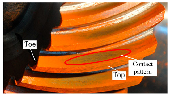
Figure 1.
Contact pattern photos.
These contact patterns are crucial for conducting in-depth studies on the high-performance design for the SBG. Additionally, the proposal and parameterized description of the numerical features of the contact patterns lay the foundation for the quantitative analysis of the relationship between the misalignment and contact pattern. Figure 2 illustrates the parameterized description of the contact pattern on the rotating projection of gear surface, which mainly consists of the reference point PM (xM, yM) (the horizontal ordinate of the reference point is equal to the horizontal ordinate of the midpoint on the gear surface) and direction angle α.
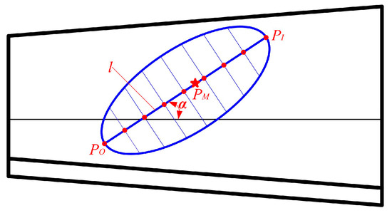
Figure 2.
Numerical characteristics of CP.
The detailed analysis method for the parametric description of contact pattern is as follows [29,30].
Based on the machining parameters of the spiral bevel gear, the long axis direction of the contact ellipse can be calculated through the TCA. Within the contour of the tooth surface imprint, parallel lines are selected at certain intervals in the direction of the long axis of the contact ellipse. The intersection points of each parallel line and the imprint contour are calculated separately, and then a polygonal area composed of these points is used to replace the continuous contact imprint. The calculation of the imprint area and center point coordinates is converted into the calculation of the polygonal area and center of gravity.
With the flank equation, the contact ellipse’s major-axis direction can be calculated by incorporating the geometric parameters and machining parameters of the SBG. Within the contour of the contact pattern, the equidistant parallel lines along the major-axis direction are selected, and the intersections between the equidistant parallel lines and the boundary line of contact pattern are calculated; then, the polygonal area formed by these intersections represents the contact pattern.
Assuming the number of vertices of the polygonal area is N, the N-Polygon can be divided into n − 2 triangles. The formula for calculating the area of any triangle is as follows:
The calculation formula for the reference point PM (xM, yM) is as follows:
The instantaneous contact ellipse’s major-axis corresponds to the parallel line segment determined by the intersection points of the equidistant parallel lines and contact-pattern boundary line. The midpoint of the parallel line segment corresponds to the current meshing point, and the combination of these meshing points forms the CP on the gear surface. The CP can be mathematically described as a quadratic function, obtained by employing the least square method to fit the meshing points.
where ai (i = 1, 2, 3) denotes the factors of the second-order CP equation.
The direction angle α should theoretically be the angle between the tangent line of the contact trace at the reference point and the pitch cone line. Here, the calculation of the direction angle α is simplified as the angle between the line connecting the entry meshing point (PI (xI, yI)) and the exit meshing point (PO (xO, yO)), and the pitch cone line, as follows:
3. Misalignment Identification
The harsh conditions experienced by helicopters cause the gearbox body, bearing system, and shaft system in the main reducers to deform when loaded, leading to the occurrence of uncertain misalignment errors in the SBG. These uncertain misalignment errors result in the actual meshing position deviating from its ideal position, which is reflected as equivalent misalignment (Figure 3). The coordinate system Sh is the meshing coordinate system of the spiral bevel gear transmission. The coordinate systems S1 and S2 are rigidly connected to the pinion and gear, respectively, and an auxiliary coordinate system Sc is added to describe the misalignment. φ1 and φ2 are the meshing angles of the pinion and gear. ΔΣ is the shaft angle error, ΔE is the center distance error, ΔP is the pinion axial error, and ΔG is the gear axial error. The misalignment of the SBG primarily includes the shaft angle error (ΔΣ), center distance error (ΔE), pinion axial error (ΔP), and gear axial error (ΔG) [29].
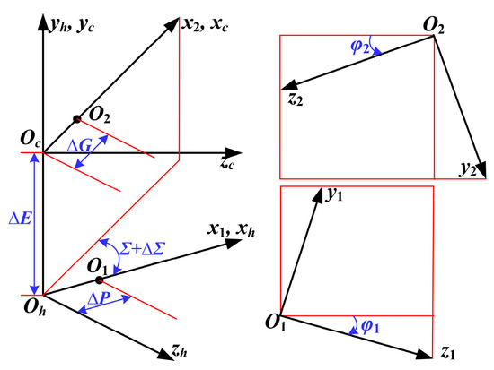
Figure 3.
The main misalignment factors.
The CP is the collection of meshing points during entire meshing process of the SBG. For the CP of the SBG under any group of misalignments, if the reference point and direction angle remain the same, then the points on the gear surface when meshing occurs will be exactly the same. The relative curvature relationship between the gear and pinion surfaces will also remain consistent, resulting in other numerical characteristics of the contact pattern being identical. By controlling the reference point and CP direction angle, the precision identification of equivalent misalignment can be achieved.
3.1. Tooth Contact Analysis
The position and normal vectors are as follows.
here, φj and θj (j = p, g) represent the flank parameters. φi (i =1, 2) is the meshing angle. Mh1, Mc2, and Mhc are the coordinate transformation matrices.
Based on the meshing coordinate system shown in Figure 3, the TCA equations are obtained as follows [38]:
In the case where a group of misalignments is known, the TCA equation consists of five independent equations and six unknown variables, and the six unknown variables are as follows: φj and θj (j = p, g) represent the flank parameters; φi (i =1, 2) is the meshing angle. By solving the TCA equation using the provided pinion meshing angle φ1, the other flank parameters φp, θp, φg, and θg and the meshing angle of the gear named φ2 are obtained. And the current meshing point is determined. The CP is composed of multiple meshing points, which are obtained by iteratively solving the TCA equation system with incremental changes in the pinion meshing angle. Thus, the reference point P′M (x′M, y′M), the entry meshing point P′I (x′I, y′I), and exit meshing point P′O (x′O, y′O) on the CP are obtained.
3.2. Equivalent Misalignment Calculate
The positioning of the engaging on the gear surface is determined by the flank parameters, meshing angle, and misalignment. When identifying misalignment, it is sufficient to determine a set of equivalent misalignments based on the CP. This approach eliminates the need for precise calculations of the exact misalignment. Instead of searching for the “true misalignment,” the focus shifts to finding the “equivalent misalignment”. This alternative approach allows for a more accurate and efficient solution to the calculation and measurement of the misalignment in the SBG. In Figure 4, the parametric diagram of gear surface’s CP is depicted, illustrating its numerical properties such as reference point coordinates P′M (x′M, y′M) and direction angle α′.
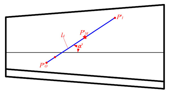
Figure 4.
The CP’s numerical properties.
With the provided misalignment, the CP (Figure 4) marked as ld is obtained with the TCA, and the reference point, entry meshing point, and exit meshing point on the CP ld are
where D represents misalignment and P′j represents a point on the CP.
Then the direction angle of the CP ld can be obtained as follows:
When the CP direction angle and reference point are identical, the contact pattern remains unchanged, resulting in the same performance for the SBG in both cases. Then, a mathematical model (Equation (11)) is introduced, where the objective is to minimize deviation in the CP direction angle and reference point between two CPs. The variables represent equivalent misalignment. The equivalent misalignment of the SBG under actual operating conditions is obtained by solving the optimization model using the simulated annealing-gravity search cooperative intelligent optimization algorithm.
4. Flank Redesign Under Equivalent Misalignment
To improve the performance of the SBG under equivalent misalignment, the redesign of the pinion surface incorporating the identified misalignment is carried out. The pinion’s processing parameters are then adjusted using ease-off to achieve a SBG that exhibits a favorable meshing performance. The design of the pinion functional surface follows these basic principles: Firstly, the TE curve and CP curve, which should align with the original SBG, are planned. Secondly, the pinion’s auxiliary surface is created with the TE. Thirdly, the correction value ζ, along the instantaneous meshing line, is computed and added to pinion auxiliary surface. This process results in a pinion functional surface that exhibits a meshing performance consistent with the original SBG when positioned correctly. The position vector of the pinion functional surface is
where and
denote the auxiliary surface’s position and unit normal vectors.
The following are the modified surface’s position and unit normal vectors:
where sp and θp stand for coordinate parameters, φp and φ1 stand for the cradle and pinion meshing angle.
Hence, the normal deviations between the modified and functional surfaces are as follows:
where d stands for the machining parameters.
Finally, the optimization model (Equation (18)) is able to produce the redesigned pinion surface with the objective of lowering the normal deviation between the two surfaces.
5. Dynamics Analysis
5.1. The Lumped Mass Method
The lumped mass method is used to model the SBG, which creates a dynamic model with multiple degrees of freedom (Figure 5a) [39]. To simplify the dynamics analysis, the dynamic model is simplified to a two-dof dynamic model (Figure 5b), which only considers the rotational degrees of freedom of the gear and pinion, and the two-dof can be simplified to the direction of the meshing line. The dynamic equation is then derived by incorporating the excitation from the meshing stiffness, loaded TE, and meshing impact (Fs) into the dynamic model as described below:
where Fn stands for the normal load, Ii (i = 1, 2) represents a moment of inertia, Ti (i = 1, 2) represent torque, and ri (i = 1, 2) represents the equivalent base circle radius at the reference point.
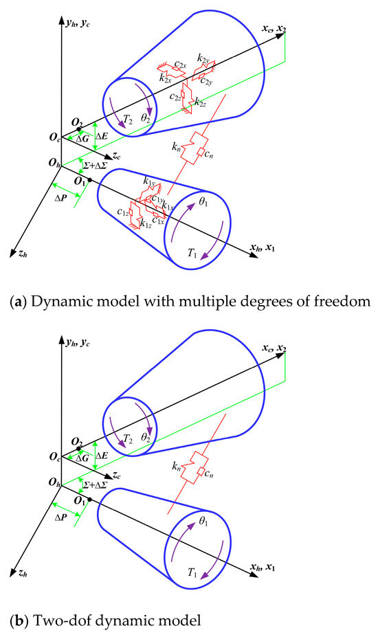
Figure 5.
Dynamic model based on lumped mass method.
However, the meshing stiffness excitation and loaded TE excitation are determined using LTCA, and the meshing impact excitation is determined using the impact theory [40,41]. Then the relative displacement along the normal direction of the meshing point between the tooth surfaces of the gear and pinion is calculated, and the vibration velocity and acceleration of the SBG are obtained by calculating the first and second derivatives of the relative displacement.
5.2. Structural Dynamics Method
The fundamental principle of structural dynamics for the SBG is depicted in Figure 6.
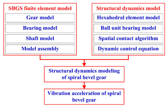
Figure 6.
The basic principle of structural dynamics.
- (1)
- Establishment of meshing model for the spiral bevel gear
According to the machining principle of the spiral bevel gear, the coordinates of discrete points on the tooth surface are generated using machining parameters as variables and tooth surface equations as the basis.
The array of discrete points on the tooth surface is filled to form a point cloud. By programming according to the definition of elements in the finite element theory, an accurate mesh model of the spiral bevel gear can be obtained. Based on the meshing equation of the spiral bevel gear, the contact relationship and relative position between the gear and pinion, the coordinate transformation matrix, is obtained. The node coordinates of the gear and pinion can be transformed from the local coordinate system to the assembly coordinate system through a coordinate transformation matrix to achieve the assembly of the spiral bevel gear (Figure 7a). The mesh generation of the web plates, shafts, and support structures can draw on the generation process of gear models, generate discrete nodes through basic dimensional parameters, and then write mesh elements.
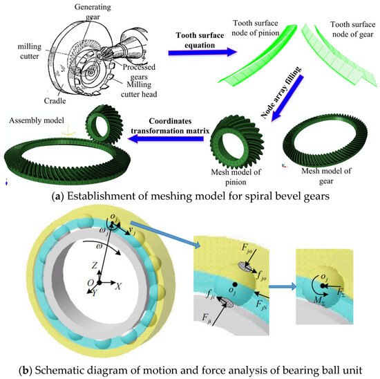
Figure 7.
Structural dynamics.
- (2)
- Establishment of structural dynamic model
A simplified calculation model of a 3D hexahedron element is built using the structural mechanics theory. By utilizing a reverse motion solving method, the calculation expression for the hexahedron element is obtained. The novel ball element bearing model is proposed based on the characteristics of helicopter ball bearings. The force on ball element is obtained based on the contact analysis between the inner and outer rings, ball element, and cage (Figure 7b). By leveraging established spatial contact algorithms and integrating the contact features of the high-speed SBG and bearings, the contact calculation model and spatial contact algorithm tailored for structural dynamics are developed. Drawing from the meshing damping model of the gear dynamics theory, the relative velocity between the pinion and gear is utilized for calculating the meshing damping force, which is then used to define damping and introduce a variable damping model. Furthermore, the dynamic control equations for improving the structural dynamics are obtained.
- (3)
- Establishment of structural dynamic model for spiral bevel gears
Combining the meshing model for the spiral bevel gear with the structural dynamic model, a structural dynamic model for the spiral bevel gear is built up. The vibration acceleration of the spiral bevel gear is determined with the structural dynamic model of the spiral bevel gear.
6. Numerical Example
To assess the success of the collaborative design of shape and performance for the SBG while accounting for uncertain misalignment errors, an analysis of a helicopter SBG is conducted as a case study. The geometric and processing parameters of the SBG can be found in Table 1 and Table 2. The actual misalignment of the original SBG under real operating conditions was named as Da, and the actual CP shown in Figure 8 and Table 3 was obtained based on the parametric description of the contact pattern.

Table 1.
Geometric parameters.
Table 2.
Processing parameters.
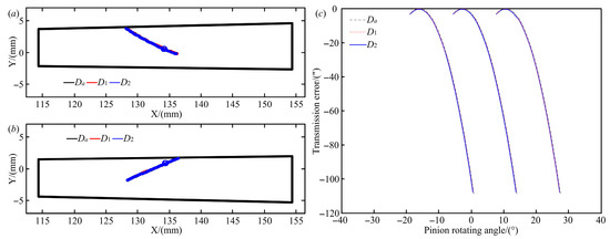
Figure 8.
Meshing performances of the original SBG in different groups of misalignments (a–c).
Table 3.
Numerical characteristics of CP.
The standard position of the original SBG was named D0; two groups of equivalent misalignments of the original SBG in real working conditions were determined using the identification method for the equivalent misalignment (Equation (11)) and named D1 and D2 (Table 4). The meshing quality of the original SBG in different groups of misalignments were analyzed using the TCA, and the corresponding CPs and TEs were obtained and listed in Figure 8 and Table 3. Compared with the actual CP, the deviations in the reference points on the CPs of the gear and pinion under the equivalent misalignment D1 were 0.0113 mm and 0.0099 mm, respectively; the deviations in the CP direction angle of the gear and pinion under the equivalent misalignment D1 was 0.0550° and 0.0115°, respectively. The deviations in the reference points on the CPs of the gear and pinion under the equivalent misalignment D2 were 0.0043 mm and 0.0140 mm, respectively, the deviations in the CP direction angle of the gear and pinion under the equivalent misalignment D2 were 0.0369° and 0.0180°, respectively. Therefore, the numerical characteristics of the CPs of the gear and pinion under the equivalent misalignment generated based on the identification method for the equivalent misalignment were very close to the actual CP of the SBG under the actual working conditions. For the CP of the SBG under any groups of misalignments, when their reference points and direction angles are the same, the meshing points on gear surface are exactly the same. The relative curvature relationship between the gear and pinion surfaces is also consistent, which will result in other numerical characteristics of the contact pattern being the same, and indicating that the equivalent misalignment has been successfully rectified with high precision.
Table 4.
Values of misalignment.
The pinion surfaces whose CP and TE under the equivalent misalignments D1 and D2 were consistent with the original SBG without misalignment were created using ease-off. The pinions’ modified surfaces and their machining parameters (Table 2) were derived based on the pinion redesign method considering equivalent misalignment. Based on the gear surface equation, the flank deviation of the redesigned pinion is generated (Figure 9). It is shown that the maximum deviation of the redesigned pinion surface under two groups of equivalent misalignments is only 1 µm. As shown in Figure 10, the CPs and TEs of the redesigned SBG under the equivalent misalignments D1 and D2 are obtained with the TCA.
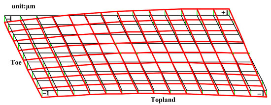
Figure 9.
Difference surface of redesigned pinion surface with equivalent misalignment.
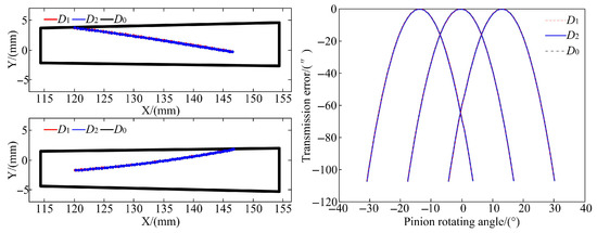
Figure 10.
Meshing performance of redesigned gear based on equivalent misalignment.
Through analysis, it was found that their TEs and CPs were basically consistent. For different groups of equivalent misalignments, the absolute positions of the gear and pinion in the meshing coordinate system are different, which results in the different machining parameters for the redesigned pinion surface, as shown in Table 2. But the relative position of the gear and pinion is the same, which determines that the micro geometry of the redesigned pinion surface is also the same, with the same gear, and the meshing performances of the SBG with the redesigned pinion are also basically the same. In theory, for completely equivalent different misalignment combinations, the machining parameters of the redesigned pinion surface using the same method will result in completely identical flank geometry, and the SBG composed of the redesigned pinion and same gear have exactly the same performance. Therefore, for the redesign of pinion under the actual working conditions, there is no need to accurately identify the uncertain misalignment errors caused by the deformation of the gear support system. There is only a need to calculate a group of equivalent misalignments and redesign the pinion surface under the group of equivalent misalignments using the collaborative design method.
The identification and equivalence analysis of the equivalent misalignment based on the TCA only reflect the no-load meshing performance of the SBG. To verify the equivalence of the equivalent misalignment obtained using the collaborative design method for the SBG considering the uncertain misalignment errors, it is necessary to analyze the contact pattern of the SBG under working conditions. And there is a strict correspondence between the contact pattern and tooth stress under the specific loads and boundary conditions. Here, when the load is 2000 Nm, the loaded performances of the original SBG under a standard position and the redesigned SBG under the groups of equivalent misalignments D1 and D2 are calculated with LTCA and illustrated in Figure 11 and Table 5. In Figure 11a, the maximum contact stress of the original SBG under the standard position is 1001.5444 MPa, and the maximum contact stresses of the redesigned SBG under equivalent misalignments D1 and D2 are 1000.3946 MPa (0.1148%) and 1002.2740 MPa (0.0728%); therefore, the percentage deviation of the maximum contact stress between the redesigned SBG and original SBG is less than 0.2%, and the percentage deviation of the maximum contact stress of the redesigned SBG under the different groups of equivalent misalignment is only 0.1879%. Analysis of Figure 11b reveals that the maximum tensile stress on gear of the original SBG under the standard position is 309.7505 MPa, and the maximum tensile stresses on the gear of the redesigned SBG under the equivalent misalignments D1 and D2 are 310.9788 MPa (0.3965%) and 309.9731 MPa (0.0719%). Through analysis, it is found that the percentage deviation of the maximum tensile stresses on the gear between the redesigned SBG and original SBG is less than 0.4%, and the percentage deviation of the maximum tensile stress on the gear of the redesigned SBG under the different groups of equivalent misalignments is only 0.3234%. As shown in Figure 11c, it is found that the maximum tensile stress on the pinion of the original SBG under the standard position is 202.5837 MPa, and the maximum tensile stresses on the pinion of the redesigned SBG under the equivalent misalignments D1 and D2 are 202.2701 MPa (0.1548%) and 201.2235 MPa (0.6714%). Through data analysis, it is found that the percentage deviation of the maximum tensile stress on the pinion between the redesigned and original SBG is less than 0.7%, and the percentage deviation of the maximum tensile stress on the pinion of the redesigned SBG under the different groups of equivalent misalignments is only 0.5174%. In summary, the different groups of equivalent misalignments result in the different machining parameters of the redesigned pinion, but the maximum tooth stresses of the original SBG under the standard position and redesigned SBG under equivalent misalignment are basically consistent, and their tooth stress curves throughout the entire meshing process are also basically match, indicating that their loaded deformation and tooth force are basically the same, resulting in an identical contact pattern on the gear surface. So, the collaborative design method can obtain a high-performance SBG whose meshing performance considering the uncertainty misalignment errors is consistent with the original SBG in the perfect environment. That is to say, this method can eliminate the impact of the uncertain misalignment errors caused by loaded deformation of the gear support system.
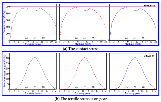
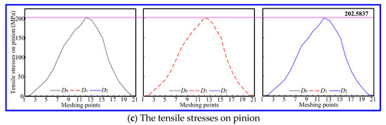
Figure 11.
The tooth stresses of the SBG.
Table 5.
LTCA results.
To substantiate the effectiveness of the collaborative design method in reducing the impact of uncertainty errors caused by the loaded deformation of the gear support system on the meshing performance of the SBG, it is necessary to compare and analyze the dynamic performance of the SBG under working conditions. Here, when the load is 2000 Nm and the input speed is 10,000 rpm, the vibration acceleration of the original SBG under the standard position and the redesigned SBG under equivalent misalignment are calculated with the help of the lumped mass method and the structural dynamics theory, and presented in Figure 12 and Table 6.
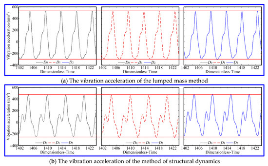
Figure 12.
The vibration acceleration of the SBG.
Table 6.
Dynamic performance.
In Figure 12a, according to the lumped mass method, the root mean square of vibration acceleration (RMA) of the original SBG under the standard position is 260.6903 m/s2, and the RMA of the redesigned SBG under the equivalent misalignments D1 and D2 are 262.5036 MPa (0.5805%) and 259.8249 MPa (0.3320%); therefore, the percentage deviation of the RMA between the redesigned and original SBG is less than 0.6%, and the percentage deviation of the RMA of the redesigned SBG under the different groups of equivalent misalignments is only 1.0216%. As seen from Figure 12b, based on the method of structural dynamics, the RMA of the original SBG under the standard position is 250.3621 MPa, and the RMA of the redesigned SBG under the equivalent misalignments D1 and D2 are 251.1382 MPa (0.3100%) and 249.8363 MPa (0.2100%). Through data analysis, it is found that the percentage deviation of the RMA between the redesigned SBG and original SBG is less than 0.5%, and the percentage deviation of the RMA of the redesigned SBG under the different groups of equivalent misalignments is only 0.5184%. In summary, the different groups of equivalent misalignments result in different machining parameters of the surface, but the RMA of the original SBG under the standard position and the redesigned SBG under equivalent misalignment are basically consistent. Although there is a slight deviation between the structural dynamics results and the lumped mass method results, the fluctuation rules of the vibration acceleration curves obtained by the two methods also basically match, indicating that their dynamic performances are basically the same. Therefore, the collaborative design method can obtain a high-performance SBG whose meshing performance considering the uncertainty errors is consistent with the original SBG under ideal working conditions. That is to say, this method can eliminate the impact of uncertainty errors caused by loaded deformation on the transmission performance of the SBG.
7. Conclusions
To ensure the stable operation of an aviation transmission system and enhance the meshing quality of the SBG in real-world conditions, the collaborative design of shape and performance for the SBG considering the uncertain misalignment errors caused by the loaded deformation of the gear support system was put up. The simulation analysis led to the following insightful conclusions.
- (1)
- With the digital feature extraction of the contact pattern of the SBG in real-world scenarios, the equivalent misalignment can be identified using the optimal model aimed at reducing the deviation in reference point and direction angle of the CP. The reference point coordinate and the direction angle of the CP named ld are very similar to those of the CP named la. For the CP of the SBG under any groups of misalignments, when their reference point and direction angle are the same, the meshing points on gear surface are exactly the same. The relative curvature relationship between the gear and pinion surfaces is also consistent, which will result in the other numerical characteristics of the contact pattern being the same, and indicating that the equivalent misalignment has achieved a high level of solving accuracy.
- (2)
- According to ease-off, the pinion working surfaces with good performances are redesigned with different groups of equivalent misalignments. And the maximum deviation of the redesigned pinion surfaces with different groups of equivalent misalignments is only 1 µm. For different equivalent misalignments, the absolute positions of the gear pair in the meshing coordinate system are different, which results in different machining parameters for the redesigned pinion. But the relative position of the gear pair is basically the same, which determines that the redesigned pinion surface is also basically the same.
- (3)
- Using the TCA and LTCA, the meshing performances of the redesigned SBG under equivalent misalignment are compared with the original SBG in real-world scenarios. The TCA results showed that the CP and TE of the redesigned SBG under equivalent misalignment are consistent with the original SBG in real-world scenarios. LTCA results showed that the percentage deviation in the maximum contact stress between the redesigned SBG and original SBG is less than 0.2%, the percentage deviation of the maximum tensile stresses on gear between the redesigned SBG and original SBG is less than 0.4%, and the percentage deviation in the maximum tensile stress on the pinion between the redesigned and original SBG is less than 0.7%. In other words, the maximum contact stresses and maximum tensile stresses of the redesigned SBG under equivalent misalignment are consistent with the original SBG in real-world scenarios, and the tooth stress curves throughout the entire meshing process also basically match, indicating that the loaded deformation and tooth force of the SBG are basically the same. This indicates that the redesigned gear has a good meshing performance, and the equivalence of equivalent misalignment is also verified.
- (4)
- Based on the lumped mass method and structural dynamics theory, the dynamic performances of the redesigned SBG under the different groups of equivalent misalignments are analyzed and compared with the original SBG in real-world scenarios. The dynamic analysis results showed that the percentage deviation in the RMA with the lumped mass method between the redesigned and original SBG is less than 1%, and the percentage deviation in the RMA with the structural dynamics method between the redesigned SBG and original SBG is less than 0.5%. That is to say, the RMA of the original SBG in real-world scenarios and the redesigned SBG under the equivalent misalignment are basically consistent. Although there is a slight deviation between the structural dynamics results and the lumped mass method results, the fluctuation rules of the vibration acceleration curves obtained by the two methods also basically match, indicating that the dynamic performance of the SBG is basically the same. This indicates that the redesigned gear has a good meshing performance, and the equivalence of equivalent misalignment is also verified.
Author Contributions
Conceptualization, Y.M. and X.H. (Xiangying Hou); data curation, Y.M.; formal analysis, Y.M.; funding acquisition, Y.M.; methodology, Y.M. and X.H. (Xiangying Hou); resources, X.H. (Xueming He); supervision, F.X.; visualization, F.X.; writing—original draft, Y.M. All authors have read and agreed to the published version of the manuscript.
Funding
This research was funded by the National Science Foundation of China, grant numbers 52205056 and 51975251. This research was funded by China Postdoctoral Science Foundation, grant number 2023M731424. This research was funded by Jiangsu Province Engineering Research Center of High-Level Energy and Power Equipment, grant number JSNYDL-202403.
Institutional Review Board Statement
Not applicable.
Informed Consent Statement
Not applicable.
Data Availability Statement
The original contributions presented in this study are included in the article. Further inquiries can be directed to the corresponding author.
Acknowledgments
We thank all reviewers and editors for their valuable comments and suggestions.
Conflicts of Interest
The authors declare no conflicts of interest.
References
- Simon, V. Optimal machine tool setting for hypoid gears improving load distribution. ASME J. Mech. Des. 2001, 123, 577–582. [Google Scholar] [CrossRef]
- Simon, V. Computer simulation of tooth contact analysis of mismatched spiral bevel gears. Mech. Mach. Theory 2007, 42, 365–381. [Google Scholar] [CrossRef]
- He, D.; Ding, H. A new analytical identification approach to the tooth contact points considering misalignments for spiral bevel or hypoid gears. Mech. Mach. Theory 2018, 121, 785–803. [Google Scholar] [CrossRef]
- Tang, J.Y. Error tooth contact analysis of spiral bevel gears transmission. Chin. J. Mech. Eng. 2008, 44, 1138–1139. [Google Scholar] [CrossRef]
- Tang, J.Y.; Du, J. Active design method of spiral bevel gears considering mounting error sensitivity. China Mech. Eng. 2009, 20, 1197–1202. [Google Scholar]
- Hu, Z.H.; Ding, H. Numerical determination to loaded tooth contact performances in consideration of misalignment for the spiral bevel gears. Int. J. Mech. Sci. 2018, 151, 110261. [Google Scholar] [CrossRef]
- Guan, Y.B.; Fang, Z.D. Tooth contact analysis of crown gear coupling with misalignment. Mech. Mach. Theory 2019, 126, 295–311. [Google Scholar] [CrossRef]
- Litvin, F.L.; Chen, J.S.; Sep, T.M.; Wang, J.C. Computerized simulation of transmission errors and shift of bearing contact for face-milled hypoid gear drive. ASME J. Mech. Des. 1995, 117, 262–268. [Google Scholar] [CrossRef]
- Simon, V. Influence of tooth errors and misalignments on tooth contact in spiral bevel gears. Mech. Mach. Theory 2007, 43, 1253–1267. [Google Scholar] [CrossRef]
- Liu, G.L.; Zhang, R.T.; Zhao, N. Quantitative analysis of the influence of installation errors on the contact pattern of spiral bevel gears. Appl. Mech. Mater. 2011, 86, 278–282. [Google Scholar] [CrossRef]
- Vivet, M.; Tamarozzi, T.; Desmet, W.; Mundo, D. On the modelling of gear alignment errors in the tooth contact analysis of spiral bevel gears. Mech. Mach. Theory 2021, 155, 104065. [Google Scholar] [CrossRef]
- Su, Y.L.; Xu, M. Tooth contact analysis of spiral bevel gear based on assembly misalignment. J. Xi’an Univ. Technol. 2017, 33, 107–112. (In Chinese) [Google Scholar] [CrossRef]
- Wang, Z.; Jian, Y. Analysis and study on the influence of installation error on spiral bevel gear tooth surface contact trajectory. J. Mech. Transm. 2014, 38, 21–24. (In Chinese) [Google Scholar]
- Fang, Z.D.; Cao, X.M. Inverse evaluation of equivalent misalignment under real operating mode and redesign of aviation spiral bevel gears. China Mech. Eng. 2007, 18, 3001–3005. (In Chinese) [Google Scholar]
- Ni, G.X.; Song, C.S.; Fang, Z.; Zhang, Z. Effects of geometric design parameters and misalignments on contact ellipse of crossed beveloid gears. Mech. Mach. Theory 2021, 165, 104441. [Google Scholar] [CrossRef]
- Kumar, P.; Hirani, H.; Agrawal, A.K. Effect of gear misalignment on contact area: Theoretical and experimental studies. Measurement 2019, 132, 359–368. [Google Scholar] [CrossRef]
- Yang, X.; Song, C.; Zhu, C.; Liang, C.; Sun, R. Impacts of misalignments on mesh behaviors of face-hobbed hypoid gear considering system deformation. IEEE Access 2019, 7, 79244–79253. [Google Scholar] [CrossRef]
- Guan, Y.; Fang, Z.; Yang, X.; Chen, G. Effects of misalignment and crowning on contact characteristics of crown gear coupling. Proc. Inst. Mech. Eng. Part C J. Mech. Eng. Sci. 2019, 233, 4397–4417. [Google Scholar] [CrossRef]
- Song, B.; Chen, J.; Zhou, Z.; Rong, K.; Zhao, J.; Ding, H. Sensitive misalignment oriented loaded contact pressure regulation model for spiral bevel gears. Mech. Mach. Theory 2023, 188, 105410. [Google Scholar] [CrossRef]
- Yang, L.; Zeng, Q.; Yang, H.; Wang, L.; Long, G.; Ding, X.; Shao, Y. Dynamic characteristic analysis of spur gear system considering tooth contact state caused by shaft misalignment. Nonlinear Dyn. 2022, 109, 1591–1615. [Google Scholar] [CrossRef]
- Lu, X.; Zhang, J.; Ma, L.; Lin, J.; Wang, J.; Wang, J.; Dai, H. Effects of misalignment on the nonlinear dynamics of a two-shaft rotor-bearing-gear coupling system with rub-impact fault. J. Vibroeng. 2017, 19, 5960–5977. [Google Scholar] [CrossRef]
- Wang, P.; Xu, H.; Ma, H.; Han, H.; Yang, Y. Effects of three types of bearing misalignments on dynamic characteristics of planetary gear set-rotor system. Mech. Syst. Signal Process. 2022, 169, 108736. [Google Scholar] [CrossRef]
- Hu, Y.H.; Du, Q.G.; Xie, S.H. Nonlinear dynamic modeling and analysis of spur gears considering uncertain interval shaft misalignment with multiple degrees of freedom. Mech. Syst. Signal Process. 2023, 193, 110261. [Google Scholar] [CrossRef]
- Zhao, G.; Guo, J.N.; Wang, X.F.; Liu, Z.S. Dynamics of rotor-gear coupling-bearing system with misalignment. J. Dalian Univ. Technol. 2011, 132, 359–368. [Google Scholar]
- Xie, S.; Du, Q.; Hu, Y. Nonlinear dynamic modeling and analysis of spur gears considering dynamic contact state under misalignment errors. Int. J. Non-Linear Mech. 2023, 152, 104401. [Google Scholar] [CrossRef]
- Simon, V. Machine-tool settings to reduce the sensitivity of spiral bevel gears to tooth errors and misalignments. ASME J. Mech. Des. 2008, 130, 082603. [Google Scholar] [CrossRef]
- Simon, V. Optimal tooth modifications in face-hobbed spiral bevel gears to reduce the influence of misalignments on elastohydrodynamic lubrication. ASME J. Mech. Des. 2014, 136, 071007. [Google Scholar] [CrossRef]
- Bai, B.; Kuang, Y.; Guo, W.; Mao, S.; Mucchi, E. Influence of misalignment on beveloid gear tooth contact and dynamic characteristics in transfer case transmission of AWD Vehicle. Shock Vib. 2021, 2022, 7565845. [Google Scholar] [CrossRef]
- Cai, X.W.; Fang, Z.D. Redesign of pinion surface for spiral bevel gears with misalignment. J. Harbin Inst. Technol. 2015, 47, 57–62. (In Chinese) [Google Scholar]
- Mu, Y.; Xie, F.; He, X. An ease-off tooth surface redesign for spiral bevel gears considering misalignment under actual working conditions. Trans. Can. Soc. Mech. Eng. 2023, 47, 618–625. [Google Scholar] [CrossRef]
- Chen, P.; Wang, S.; Li, F.; Zou, H. A direct preset method for solving ease-off tooth surface of spiral bevel gear. Mech. Mach. Theory 2023, 179, 105123. [Google Scholar] [CrossRef]
- Wang, Q.; Jiang, J.; Chen, H.; Tian, J.; Su, Y.; Guo, J. Design and analysis for hypoid gears with ease-off flank modification. Appl. Sci. 2022, 12, 822. [Google Scholar] [CrossRef]
- Wang, Q.; Zhou, C.; Gui, L.; Fan, Z. An ease-off based approach to designing a high-order transmission motion for face-milled spiral bevel gears. Int. J. Veh. Des. 2019, 81, 241–264. [Google Scholar] [CrossRef]
- Mu, Y.M.; He, X.M.; Fang, Z.D. Design and dynamic performance analysis of high-contact-ratio spiral bevel gear based on ease-off technology. Int. J. Precis. Eng. Manuf. 2021, 22, 1963–1973. [Google Scholar] [CrossRef]
- Mu, Y.M.; He, X.M.; Fang, Z. An innovative ease-off flank modification method based on the dynamic performance for high-speed spiral bevel gear with high-contact-ratio. Mech. Mach. Theory 2021, 162, 104345. [Google Scholar] [CrossRef]
- Mu, Y.M.; He, X.M. Design and dynamic performance analysis of high-contact-ratio spiral bevel gear based on the higher-order tooth surface modification. Mech. Mach. Theory 2021, 161, 104312. [Google Scholar] [CrossRef]
- Li, G.; Zhu, W.D. An active ease-off topography modification approach for hypoid pinions based on a modified error sensitivity analysis method. ASME J. Mech. Des. 2019, 141, 093302. [Google Scholar] [CrossRef]
- Su, J.Z.; Fang, Z.D.; Cai, X.W. Design and analysis of spiral bevel gears with seventh-order function of transmission error. Chin. J. Aeronaut. 2013, 26, 1310–1316. [Google Scholar] [CrossRef]
- Mu, Y.M.; Hou, X.Y.; He, X.M. Research on active precontrol strategy for shape and performance of helicopter spiral bevel gears. Appl. Sci. 2023, 13, 8527. [Google Scholar] [CrossRef]
- Mu, Y.M.; Fang, Z.D.; Zhang, X.J. Theoretical analysis on meshing impact of spiral bevel gears. J. Huazhong Univ. Sci. Technol. (Nat. Sci. Ed.) 2018, 8, 7–11. [Google Scholar] [CrossRef]
- Mu, Y.M.; Fang, Z.D.; Li, W.L. Impact analysis and vibration reduction design of spiral bevel gears. Proc. Inst. Mech. Eng. Part K J. Multi-Body Dyn. 2019, 233, 668–676. [Google Scholar] [CrossRef]
Disclaimer/Publisher’s Note: The statements, opinions and data contained in all publications are solely those of the individual author(s) and contributor(s) and not of MDPI and/or the editor(s). MDPI and/or the editor(s) disclaim responsibility for any injury to people or property resulting from any ideas, methods, instructions or products referred to in the content. |
© 2025 by the authors. Licensee MDPI, Basel, Switzerland. This article is an open access article distributed under the terms and conditions of the Creative Commons Attribution (CC BY) license (https://creativecommons.org/licenses/by/4.0/).