1. Introduction
Screw rotors are key components of screw kneaders, screw pumps and screw compressors [
1,
2,
3]. To fully take the advantages of the rotors’ helical surfaces, these fluid machines are usually of simple structure, high reliability, and low energy consumption. Meanwhile, the tolerance requirements of the helical surfaces are strict. Large geometrical errors would degrade the product performances significantly. Compared with planer and cylinder surfaces, helical surfaces are much harder to be machined due to their complex geometries. The helical surfaces on screw rotors can be manufactured by milling, grinding, plastic forming, casting and additive manufacturing [
4,
5]. Currently, disc milling is commonly used for the mass production of screw rotors with the advantages of a simple tool trajectory, high machining efficiency and good machining consistency [
6]. To achieve disc milling, the first problem to be solved is the robust and precise generation of the cutter profiles.
Traditionally, an analytical method was used for cutter profile design by solving the contact equation derived from the envelope theory of gearing [
7,
8,
9]. The obtained cutter profile can theoretically be free of error when the tooth profile can be represented by a simple function [
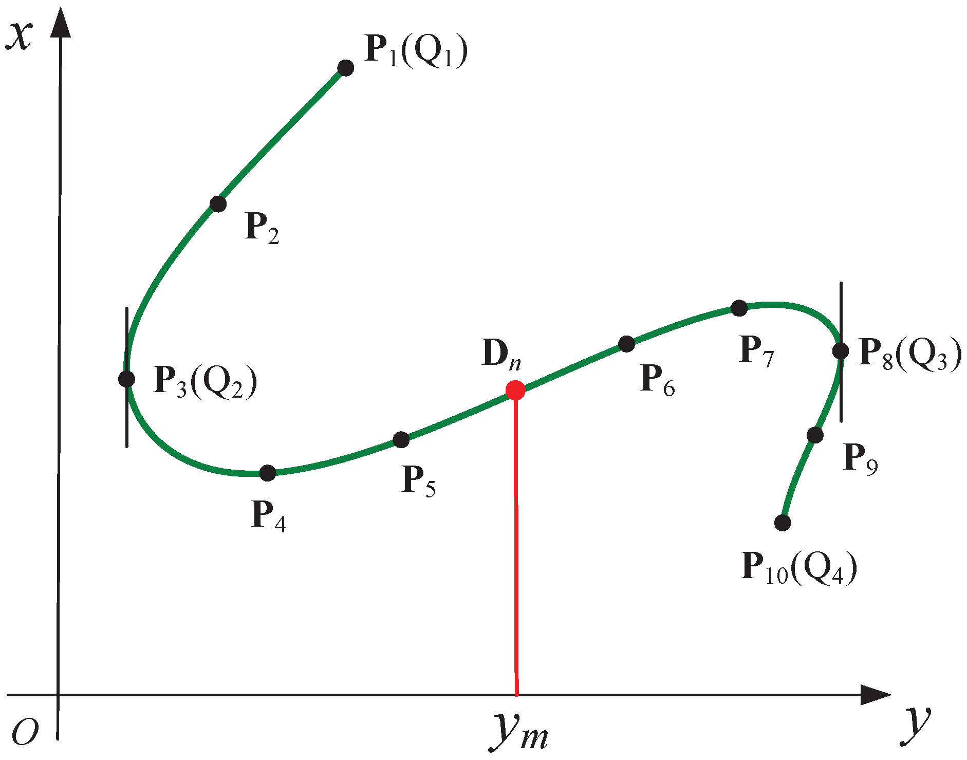
10]. However, tooth profiles are rarely expressed by a simple function but are commonly represented by discrete points [
11]. In this case, these points should be fitted by parametric methods to determine their derivative values ahead of solving the contact equations [
12]. The most common approach is to use a cubic spline to fit the rotor profile at the end planer, then build the contact equation according to the gearing enveloping theory, ultimately determining the contact line by solving the equation. A method for optimization of the installation angle and center distance was proposed by Liu [
13] based on the solution of the contact-line equation using Matlab. Achmad fit the original rotor profile using a cubic spline in order to obtain the partial derivatives at each contact point [
14]. Arifin also used a cubic spline to fit the rotor profile and to design the profile of whirling milling tools [
15]. This method has also been used to optimize the position of inserts in a disk-type milling cutter for the formed milling of screw rotors [
16]. Luu used constraints on the contact condition to generate the cutting-edge profile of an internal cylindrical skiving cutter [
17]. Su built the contact-line equation according to the meshing relationship between the worm and formed grinding wheel and solved the equation by using the fsolve method in Matlab [
18]. Li used the Newton–Raphson method to determine the points on the contact line between a formed grinding wheel and a helical gear [
19]. However, the contact-line equation is usually nonlinear and must be built by a tedious derivation procedure; therefore, it should be solved by a complex algorithm.
The disadvantages of the analytical method can be summarized as follows [
20]:
- (1)
The process of establishing the contact equations is rather complex, and solving the nonlinear contact equation requires professional math skills.
- (2)
Numerical instability easily occurs near singular points when solving the contact equations, which may lead to a faulty cutter profile.
- (3)
The fitting error and the subsequently enlarged deviation error deteriorate the accuracy of the cutter profile, especially at the end points.
To simplify the cutter profile generation processes, several numerical methods have been developed. Sun et al proposed a cutter profile generation method based on the geometric requirement that the normal vector of the helical surface at the contact line must intersect with the revolving axis of the tool [
21]. It also needs to solve a nonlinear equation to achieve a contact point. To avoid the solution of the nonlinear equations, one option is the minimum distance method, where a contact point is achieved on each of the helical curves [
22]. Thus, the machinability of the helical surface is difficult to analyze. The computational accuracy is also subject to the point density generated on the helical curves. CAD approaches have the advantages of being intuitive and effective, as the machining process is considered a process of interference of the cutter with workpiece, with the interfered portion removed by the cutter [
23,
24,
25]. The Boolean subtraction operation of the CAD approaches involves complex mathematics, and the tool surface is also required to be represented in the form of a mathematical equation. This process requires massive computations and is time consuming. The cutter designer should also be an expert in the advanced operation of the expensive software necessary to establish a 3D numerical model of the rotor. Meanwhile, the irregular distribution of triangular meshes at the intersection region between the tooth profile and cylinder significantly influences the computational accuracy [
26]. The digital graphic scanning method was developed for the generation of the grinder profile, but its accuracy is limited by the smallest pixel size [
27]. The obtained cutter profile is also discontinuous and needs to be smoothed by curve fitting.
Machinability analysis is necessary before the machining process due to the geometry complexity of screw rotors. The machinability related to the material of the cutter and rawpiece, the process parameters and the external environment could only be analyzed by conducting a milling or grinding experiment. Tao predicted the machining error of a screw rotor profile by analyzing the measurement results and then built a prediction model to determine the compensation values in order to improve the machining accuracy [
28]. Jiang used the particle swarm algorithm to calculate the minimum total grinding curve length of a wheel disc in order to equilibrate its degree of wear [
29]. Liu built a machining error influence model for the screw rotor profile considering the center distance, installation angle and grinding wheel wear [
30]. An installation parameter optimization model for the machining of the screw rotors was also built by Liu in order to improve the machining performance [
31]. A prediction model for the milling force was proposed by Wang based on the process kinematics and cutter workpiece engagement in order to reduce the error caused by cutting force [
32]. The cutting interference is the most common machinability problem related to the cutter profile design and should be carefully examined. However, the traditional tool profile design method based on solving the contact equation is incapable of detecting the cutting interference directly. In that case, a subsequent manual checking or simulation of the three-dimensional mesh model of the cutter and the workpiece is needed [
33]. This is a complex and time-consuming procedure, and the detection accuracy is limited by the precision of the three-dimensional model.
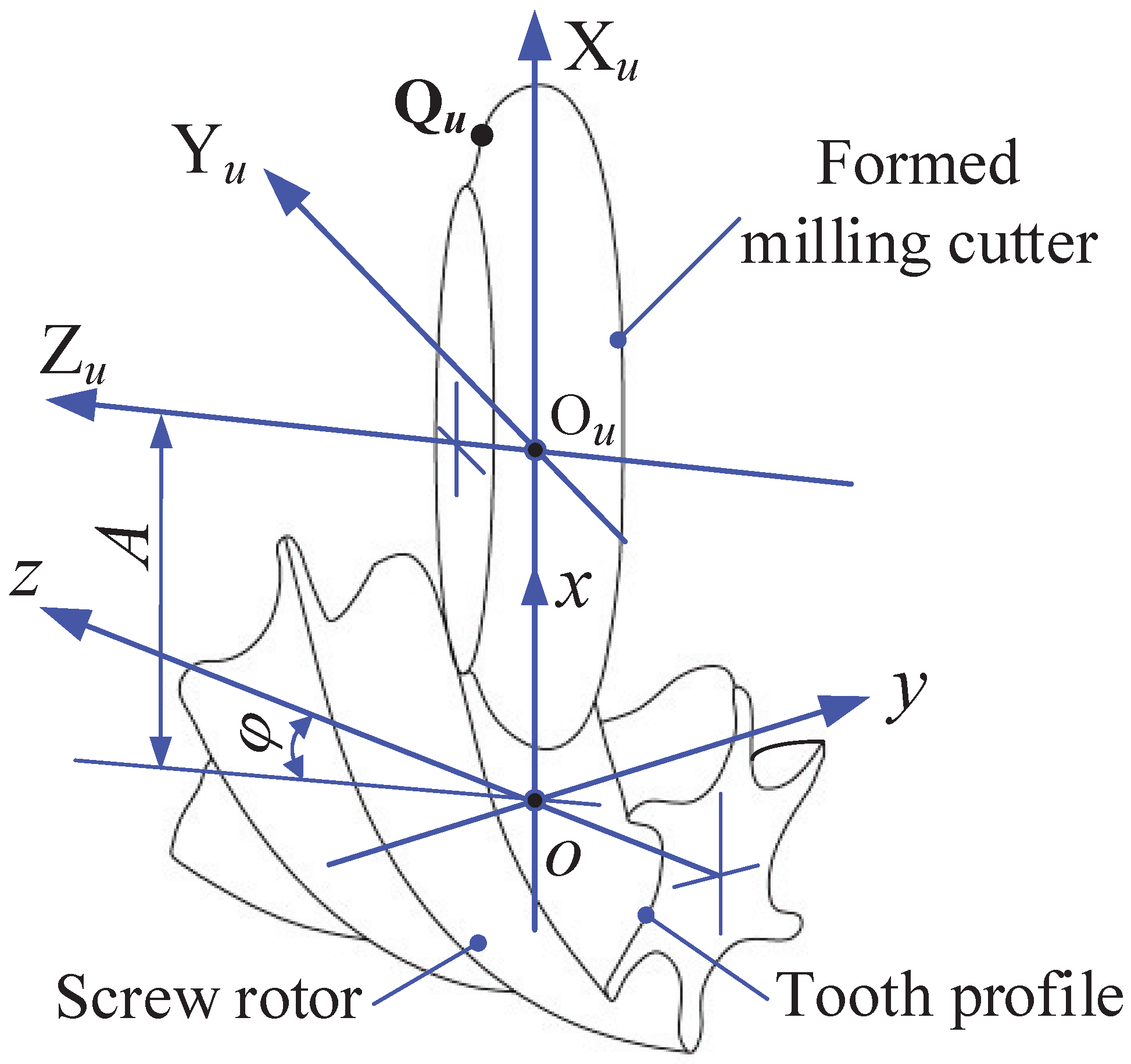
In order to simplify the procedure of formed milling cutter design for screw rotor profiles represented by either equations or discrete points, a general numerical method which does not rely on the contact line equation is proposed. Furthermore, the machinability related to the milling cutter design could be analyzed simultaneously. The rest of the paper is organized as follows. In
Section 2, the numerical method for the formed cutting tool profile design is presented. In
Section 3, two screw rotor profiles are used to verify the proposed method. In
Section 4, machinability related to the cutter profile is discussed. Finally, the conclusions are drawn in
Section 5.
3. Experiments and Discussion
The geometrical data of two screw rotors are used to generate the correspond formed cutter profiles by using the proposed numerical method. The first one has a helical surface with an arc tooth profile, which is represented by an equation of continuity. In that case, an error-free cutter profile can be obtained by using the analytical method. The cutter profile which is calculated by using the proposed numerical method is compared with the one that is calculated by using the analytical method in order to verify the computational accuracy of the proposed method. The second screw rotor has a helical surface which is represented by discrete points. The cutter profile is calculated to verify both the computational accuracy and the efficiency of the proposed numerical method.
3.1. Cutter Profile Generation for an Arc Tooth
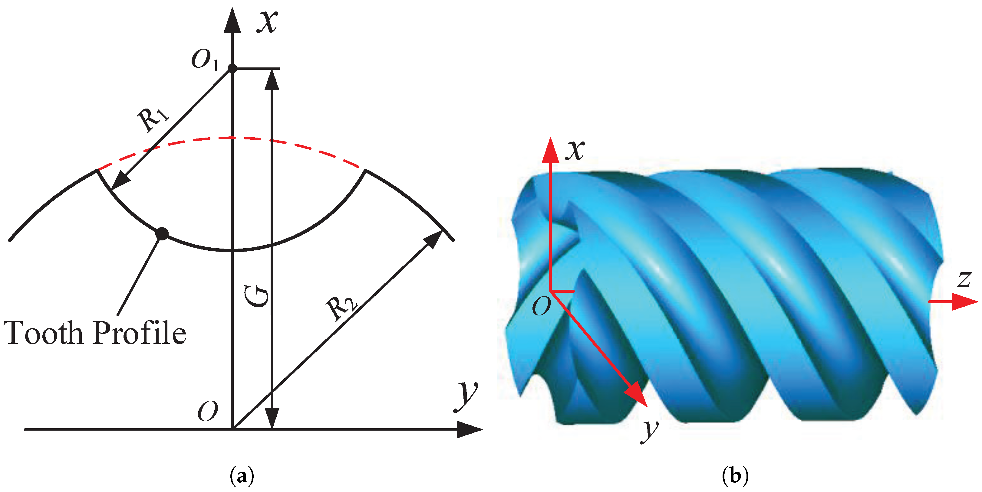
The arc tooth profile used for veficication and its 3D model are shown
Figure 6a and
Figure 6b, respectively. The function of the tooth profile is
The detailed geometry and the machining parameters are listed in
Table 1. To quantitatively evaluate the accuracy of the numerical method, the analytical method is also adopted to calculate the cutter profile where the contact equations were solved by use of the classical Levenberg–Marquardt algorithm [
35].
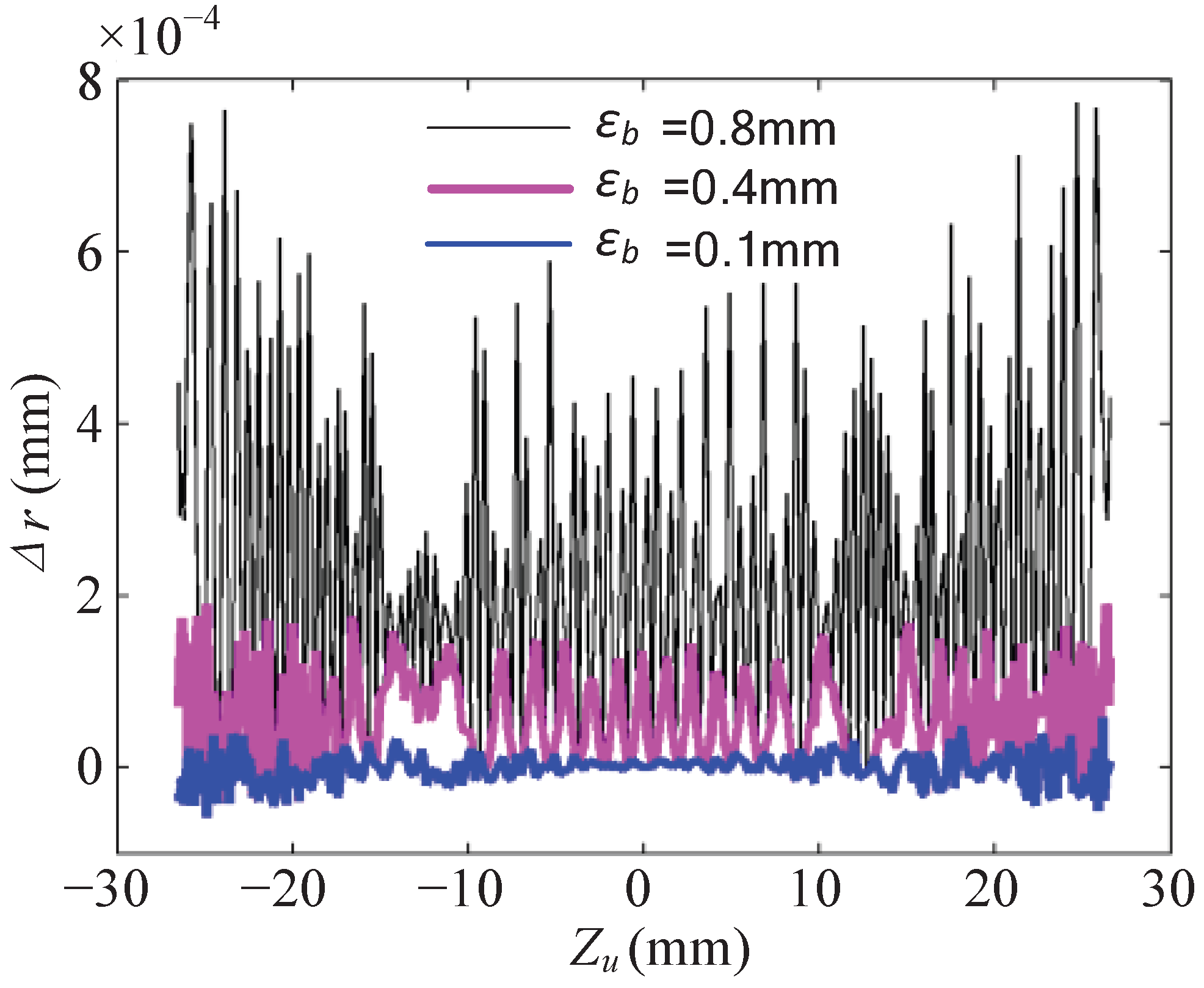
Based on the computation principle, when the tooth profile is given by discrete points, the cutter profile error generated by the proposed numerical method is only subjected to the interpolation error of the tooth profile, the computation accuracy of the intersection points between the spline and the intersection plane , and the subdivision process to find the minimum distance point. For this case, is set to mm; thus, its influence on the profile error of the cutter can be neglected. To reveal the relationship between the cutter profile error and the remaining two factors, three experimental schemes are carried out—namely, , and .
For
, points are sampled on the arc tooth profile with an equal angle of 0.01 rad. The threshold value of the subdivision is first set to
mm. For ease of comparison, the
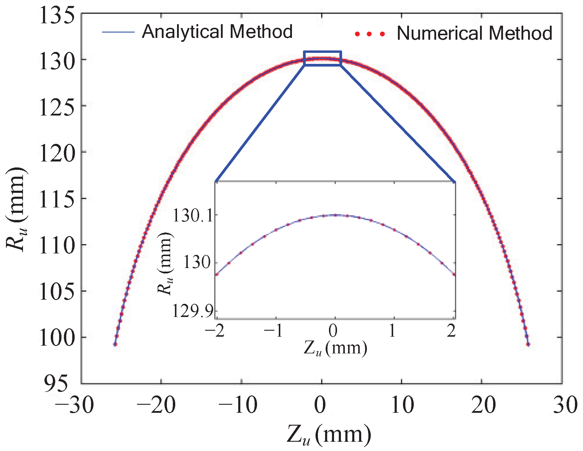
coordinates of the points of the cutter profile are generated in the same way as the ones that are used in the analytical method. The obtained cutter profiles are shown in
Figure 7, where the result of the numerical method is well accordant with the result of the analytical method. The radius deviation is computed and shown in
Figure 8. The maximum deviation (MD) is 0.7741 µm, and the root mean squares (RMS) value is 0.3111 µm. Then, the subdivision threshold value
is set to 0.4 mm and 0.1 mm, respectively, and the deviations reduce significantly. For all of the above situations, the maximum deviations are within 1 µm, which indicates the high calculation precision of the proposed numerical method.
However, when
is further decreased to 0.04 mm and 0.01 mm, the maximum deviation remained unchanged, as shown in
Table 2. As analyzed above, the error is most probably introduced by the B-spline interpolation. To verify this assumption, the experiment scheme,
, is carried out where the points are resampled on the arc tooth at an equal angle of 0.002 rad. The maximum deviations are also listed in
Table 2. When
mm, the maximum deviation value reduces to 0.0016 µm, which is far less than that in
.
For , the intersection points are obtained not by the intersection of the interpolated B-spline curve and the straight line, but by combining the tooth function and the intersection planes, where no interpolation error exists. The maximum deviation reduces to 0.0004 µm at mm. The above results indicate that the proposed method can achieve an extremely high precision when the interpolation error is well controlled.
3.2. Cutter Profile Computation for the Point Represented Tooth Profile
The surface geometry and the machining parameters of the screw rotor are listed in
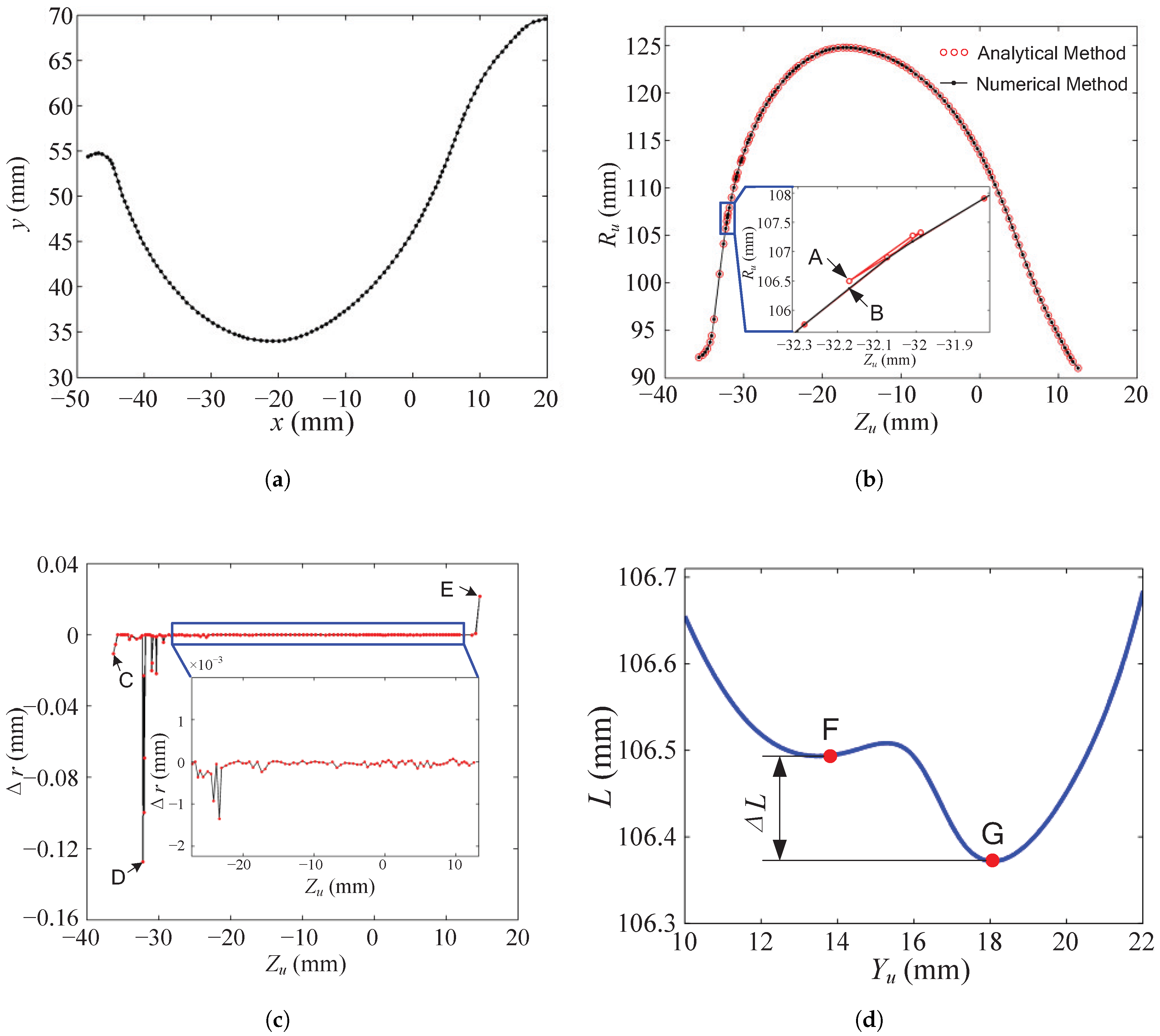
Table 3. The tooth profile of this screw rotor is represented by discrete points, as shown in
Figure 9a, where the point intervals are equal. The analytical method and the proposed numerical method are used to calculate the cutter profile according to the tooth profile, respectively. For easy comparison, the
coordinates of the points in the analytical method and the proposed numerical method are equal, and the number of points on the cutter profile is equal to the number of points on the tooth profile. Some of the coordinates of points on the tooth profile are listed in
Table A1. Some of the coordinates of points on the cutter profile generated by the analytical method are listed in
Table A2. Some of the coordinates of points on the cutter profile generated by the proposed numerical method are listed in
Table A3.
As shown in
Figure 9b, the cutter profile is calculated using an analytical method by solving the contact equations [
14]. The deviation value of each point is obtained by using cubic B-spline fitting with the multiple knots technique at the boundary. The result shows that the distribution of the points on the tool profile is no more uniform. In addition, there are several singular points, as shown in the enlarged part of this figure.
The profile of the cutter obtained by using the proposed numerical method is also shown in
Figure 9b. Most of the profile obtained by using the analytical method closely coincides with the result of the proposed numerical method. However, at the enlarged portion, the numerical method obtains a smoother profile than the analytical method.
To further compare the two cutter profiles, the deviations of
are computed as shown in
Figure 9c. The computational precision and efficiency of the numerical method and the analytical method are listed in
Table 4. The error of the numerical method is only
of that of the analytical method. The computational time of the Matlab program for the numerical method is
lower than that when using the analytical method. More importantly, the numerical method can be applied to any type of screw rotor profiles without building the contact line equation and taking its derivative, which is the most time-consuming operation of the analytical method.
The deviation curve is analyzed from three aspects:
- (1)
The boundary points obtained by the analytical method, C and E, have large deviation values. This is because the derivative values are very sensitive to the boundary condition of the interpolation, and the derivative values significantly affect the solving of the contact equations.
- (2)
The singular points obtained by the analytical method, including point D and the points nearby in
Figure 9c, have even larger deviations. The maximum deviation value at the singular point A in
Figure 9b is
mm, which is not allowed for the machining of a screw rotor.
- (3)
The deviation value of most points on the deviation curve, as shown in the expanded portion of
Figure 9c, is within 1.5 µm. This indicates that the numerical method can reach as precise results as the analytical method under normal conditions.
The intersection curve where A is located is extracted and analyzed to figure out how the singular points occur when using the analytical method. The curve of distance from the intersection point to the rotation center is plotted in
Figure 9d. The point G is the real global minimum point of the distance curve. The corresponding point on the distance curve of point A is F, which is a local minimum point obtained by the analytical method. The distance variation from F to G is
mm, which is the same as the deviation value at point D in
Figure 9c. Thus, the material near point A will be over-cut. The numerical method, on the other hand, obtained the real global minimum point.
4. Machinability Analysis
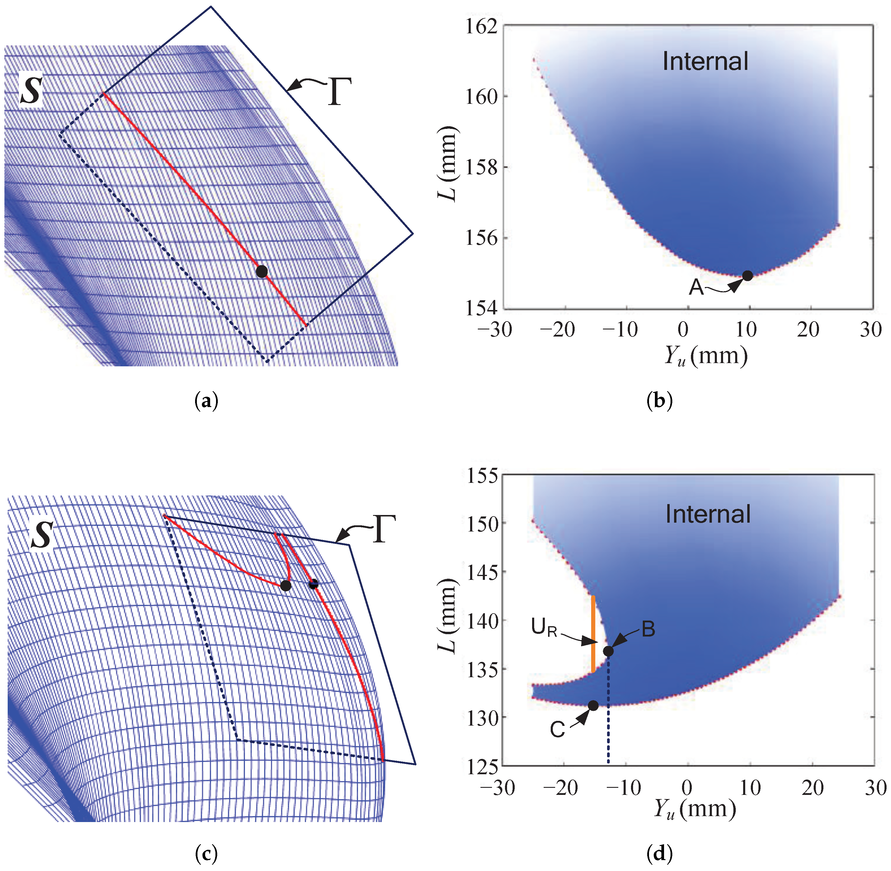
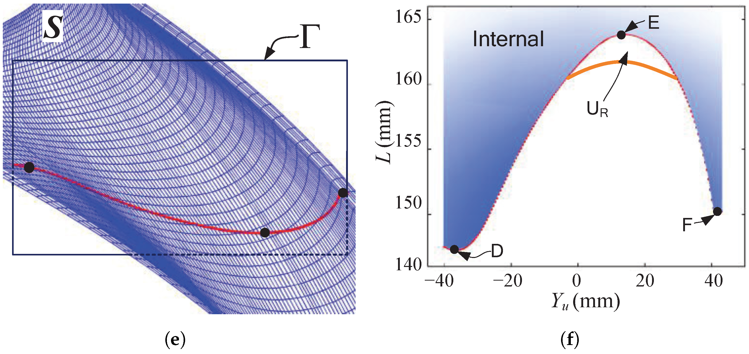
The machinability related to the cutter profile design is analyzed according to each of the intersection curves, as shown in
Figure 10, where the intersection curves between the intersection planes and the helical surfaces are denoted along with the distance curve.
When the cutter is not interfering with the helical surface within the intersection plane, as shown by
Figure 10a,b, the distance curve has a unique minimum point. The minimum value equals the radius of the cutter in this intersection plane. However, the intersection curve could be more complicated, as shown in
Figure 10c, where two intersection curves are obtained. The distance curves also consist of two curves, as shown in
Figure 10d. The point with the minimum distance can only exist on the lower curve. If C is the minimum point and C(
) < B(
), the block material above the point C, indicated by
, cannot be removed due to self-occlusion. Another interference problem case is shown in
Figure 10e,f, which usually occurs when the radius of the cutter is larger than the minimum radius of the intersection curve. A global maximum point E exists on the distance curve, and the material near this region,
, cannot be removed. Otherwise, the cutter would interfere with the internal material of the desired surface.
The machinability analysis is carried out simultaneously with the cutter profile generation process by examining each of the intersection curves. The desired helical surface can be obtained when no interference occurs.
5. Conclusions
A general numerical method is proposed to design the formed milling cutters for the machining of various kinds of helical surfaces. A group of intersection planes are built in which contact points are searched via the subdivision method and the Newton iteration method. In that case, the cutter profile could be obtained without building and solving the nonlinear contact equation, and the problem of singularities can be prevented.
Two cutter profiles are designed to verify the proposed method. The results indicate that the computational accuracy and efficiency are significantly improved compared with the commonly used analytical method. Furthermore, the machinability related to the cutter profile design can be easily justified simultaneously with the contact point searching process.
The proposed method can also be used for the profile design of the formed grinding wheels. Future work will be devoted to the cutting process analysis related to the cutting force, process parameters, tool wear and error compensation.

