1. Introduction
In precision machining and ultra-precision machining, many factors can produce machining error in CNC machine tools, such as spindle motion error, or external disturbance responses, such as thermal deformation, excessive force, and vibration [
1,
2,
3]. Spindle motion error is the most important factor in producing error [
4,
5,
6]. Several measurements are required during the machining of the workpiece to improve its manufacturing accuracy, and transferring the workpiece from the machine tool to the inspection equipment is not only time-consuming but may also introduce new installation errors. It is crucial to separate the surface morphology data of the workpiece and the spindle motion error from the detection results to obtain real surface data of the workpiece, namely error separation technology [
7,
8,
9].
As noted in Reference [
10], Donaldson et al. were the first to apply the reversal methods to separate spindle motion errors in measuring spindle rotation accuracy. This method has attracted attention because of its simple operation and ease of engineering. Subsequently, multi-sensor fusion technology has gradually become a research hotspot [
11,
12,
13]. Liu et al. proposed a three-probe error separation technique, that measured the morphology of cylindrical workpieces by contacting a measured cylinder with a double V-shaped surface [
14]. Shi et al. proposed a hybrid three-sensor detection method, and the new method has better robustness to error sources [
15]. Kim et al. developed and validated a compact curved-edge displacement sensor (CES) that can be embedded in a spindle for real-time measurement of spindle dynamic characteristics and cutting forces during machining and for high-precision process monitoring [
16]. Baek et al. developed a precision measurement method to evaluate the radial, axial, and tilt error motions of rotating devices using Fourier model-based multi-probe error separation techniques [
17]. However, an increase in the number and types of sensors inevitably increases the cost of detection and the complexity of data processing [
18,
19,
20]. Therefore, it is crucial to propose a detection method that supports multiple rotation angles and that is computationally simple.
At present, the method for detecting the rotation accuracy of a spindle is to install a standard ball or standard cylinder at the spindle end. This method typically detects the displacement signal at the standard device and then applies the error separation method to eliminate the shape error of the standard device, indirectly obtaining the rotation accuracy of the spindle [
21,
22]. However, the installation eccentricity error of a standard device can introduce systematic measurement errors, seriously restricting the engineering universality of this method. The in situ detection method of workpieces can simultaneously obtain information on machining accuracy and spindle error, providing higher detection efficiency and practicality [
23]. The three-point method is limited by first-order harmonic suppression, whereas the reversion method does not exhibit this limitation [
24,
25,
26]. Although the reversal method is simple to operate, it requires a reversal of 180° to effectively obtain spindle rotation accuracy. The difficulty in reversing large workpieces limits the application of such engineering methods [
27,
28]. Therefore, there is an urgent need to develop a surface morphology detection method with a wider range of workpiece rotation angles and more convenient calculations.
This work proposes a novel method for detecting the surface morphology of workpieces at any rotation angle. The traditional inversion method is limited to 180° rotation, while the three-point method suppresses the first harmonic in the signal. These limitations have prompted us to develop a flexible, accurate, and low-cost solution applicable to any rotation angle. The highlights of the proposed method are as follows:
- (1)
Allow the workpiece to complete the inspection at any rotation angle (no 180° constraint), with higher flexibility.
- (2)
Avoid the suppression of first-order harmonics by the three-point method and preserve complete spectral information.
- (3)
Simultaneously separate the spindle motion error and the true contour of the workpiece from the same set of data.
- (4)
Based on the extracted true contour, arithmetic mean deviation, cylindricity, and axis straightness are directly obtained, reducing on-machine inspection costs.
The rest of this work is organized as follows.
Section 2 introduces the detection method for the spindle motion error.
Section 3 depicts the separation method for the spindle motion error. In
Section 4, the simulation verification and analysis are conducted using the separation method. In
Section 5, a measurement experiment is performed, and the results are analyzed. Finally, the conclusions are presented in
Section 6.
2. Detection Method for Spindle Motion Error
As illustrated in
Figure 1, the motion error generated by the spindle during rotation includes two tilting motions and three translational motions. As indicated in
Figure 1a, the pure axial motion error
of the spindle along the
z-direction is represented. As displayed in
Figure 1b, the radial motion errors
and
of the spindle along the
x and
y axes are represented, respectively. As demonstrated in
Figure 1c, the tilt motion errors
and
of the spindle around the
x and
y directions are represented, respectively.
To ensure the stability of the machining process, the spindle’s stiffness is usually high. Therefore, spindle deformation is ignored in this work. Since the spindle is connected to the spindle box via rolling bearings, the assembly tolerances and geometric errors of the bearings will be reflected in the rotational motion of the spindle, resulting in spindle motion errors. Typically, the periodic error signals generated during spindle motion are caused by geometric errors in the raceway, known as synchronization errors, which manifest as frequency components that are multiples of the spindle speed in the frequency domain. Non-periodic error signals are caused by rolling element errors, also known as asynchronous errors. The above two types of errors together constitute the spindle motion error [
29].
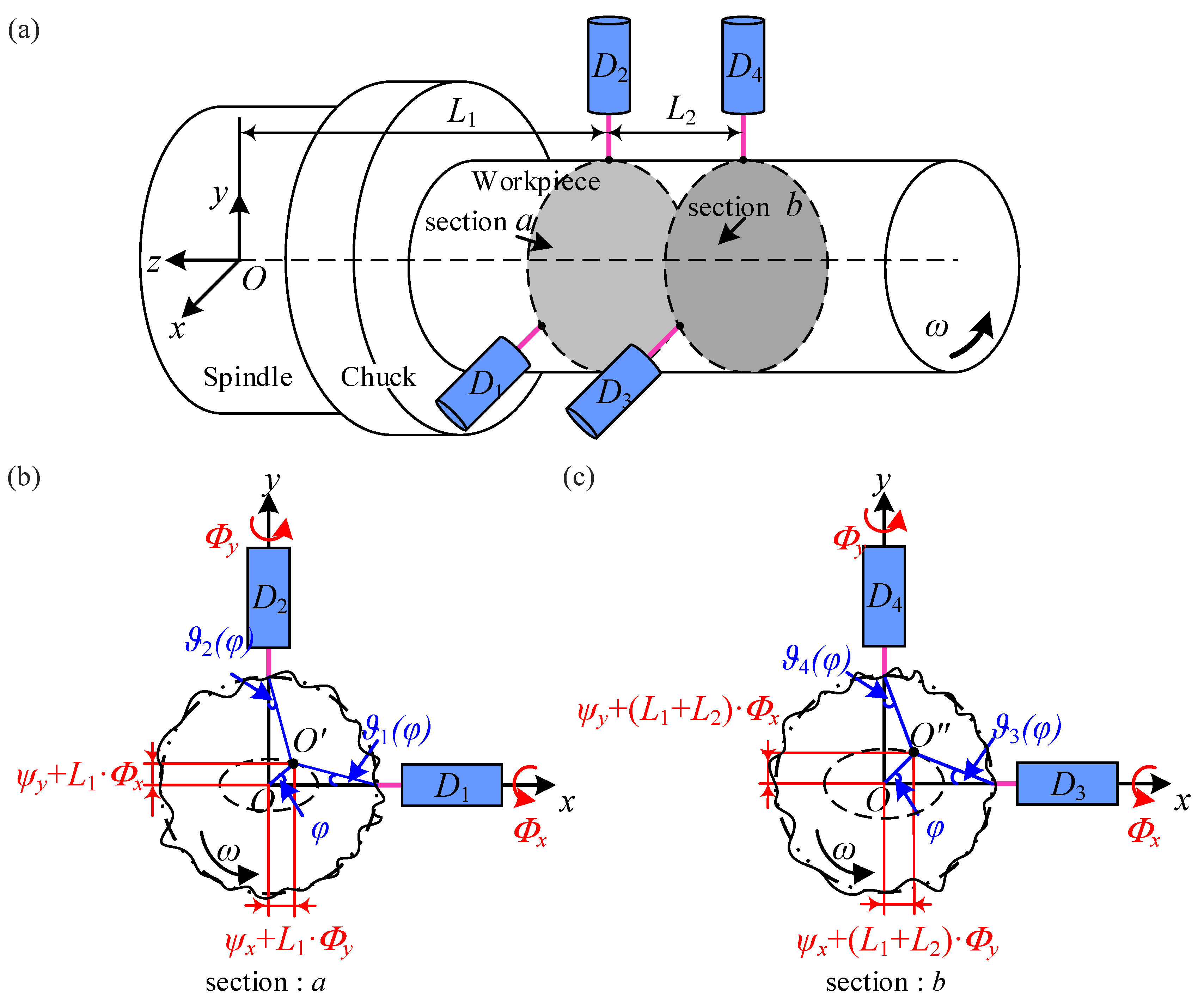
In this work, displacement sensors are used to obtain spindle motion errors. Subsequently, based on the geometric relationship between sensor readings, spindle motion errors, and workpiece morphology, spindle motion error is decoupled from workpiece shape. The sensor mounting position for the spindle motion error detection system is illustrated in
Figure 2. The workpiece is connected to the spindle through a chuck.
Oxyz is a fixed coordinate system, where O is the ideal center of the spindle when it is stationary.
is the center of rotation of section
a, and the distance between the center of the section and the center of the spindle is
L1.
is the center of rotation in section
b. The
z-axis coincides with the spindle axis, and
R is the ideal radius of the workpiece. Sensors
D1 and
D2,
D3, and
D4 were installed in sections
a and
b, respectively. The distance between the two cross-sections is
L2. Sensors
D1 and
D3 are parallel to the
x-axis of the coordinate system, and sensors
D2 and
D4 are parallel to the
y-axis of the coordinate system.
Assuming the angular position of the spindle is
φ, the actual profiles of the workpiece cross-sections
a and
b can be represented as
and
, respectively. The radial motion errors of the spindle are
and
, and the tilting errors are
and
. The readings of the four displacement sensors can be represented as follows:
Assuming that
N measurement points are uniformly distributed along the circumference of the measured cross-section of the workpiece, the position of each measurement point can be represented as
. Due to the radius of the workpiece being much larger than the motion error of the spindle, the readings of the 4 sensors in Equation (1) can be expressed as
With
and
α1 =
α3 = 0;
α2 =
α4 = π/2;
P1 =
P3 =
T2 =
T4 =
x;
P2 =
P4 =
T1 =
T3 =
y;
H1 =
H2 =
L1;
H3 =
H4 =
L1 +
L2;
q =
a for
n = 1 or 2;
q =
b for
n = 3 or 4.
3. Separation Method for Spindle Motion Error
In this section, an error separation method based on the arbitrary rotation angle of the workpiece is proposed. As can be seen from the previous section, the readings of displacement sensors contain spindle motion errors and workpiece contour information, among which spindle motion errors are composed of synchronous motion errors and asynchronous motion errors. Due to the workpiece being connected to the spindle through a chuck, the frequency of its profile information in the detection signal is completely consistent with the working frequency of the spindle, which results in coupling between the workpiece morphology and the synchronous motion error of the spindle. Unlike this, asynchronous errors have random characteristics and cannot form a fixed correlation with the contour of the workpiece. Therefore, to accurately extract the true contour of the workpiece, the signals of the spindle over
M working periods can be averaged, thereby achieving effective neutralization of asynchronous errors [
30]. At this point, the readings of the sensor within
M working periods of the spindle can be expressed as
where
n represents the sensor number,
i is the angular position, and
j is the work period of the spindle.
If the sensor readings at the initial position in Equation (4) are represented by
A, the sensor readings after the workpiece rotates are represented by
B, and the rotation angle is denoted as
βn, then we can obtain
The detection data of sensors
D1 and
D2 before and after rotation can be expressed as follows:
Similarly, the detection data of sensors
D3 and
D4 before and after rotation can be expressed as follows:
Equations (6) and (7) can be expressed in the form of a linear system of equations
AX =
b, and solving for
X can obtain the synchronization motion error
of the spindle and the actual profile
of the section. Then, by substituting the synchronization motion error
of the spindle into Equation (3), the tilting error
can be solved as follows:
the radial motion error
can be expressed as follows:
Next, an error separation method based on the arbitrary rotation angle of the workpiece was derived. When
βn = π/2, Equation (6) can be expressed as
where
.
Equation (11) is full-rank and nonsingular, and the system of equations has a unique solution. When βn = π/2, Equation (7) is similar.
When
βn = π, this method is the same as the Donaldson inversion method [
31,
32]. Equation (6) can be expressed as
where
;
.
Equation (13) is full-rank and nonsingular, and the system of equations has a unique solution. When βn = π, Equation (7) is similar.
When
βn = 3π/2, Equation (6) can be expressed as
where
;
.
Equation (15) is full-rank and nonsingular, and the system of equations has a unique solution. When βn = 3π/2, Equation (7) is similar.
In other cases, Equations (6) and (7) can be expressed in the form of linear equations and are abbreviated as
By substituting the detection data of sensors
D1 and
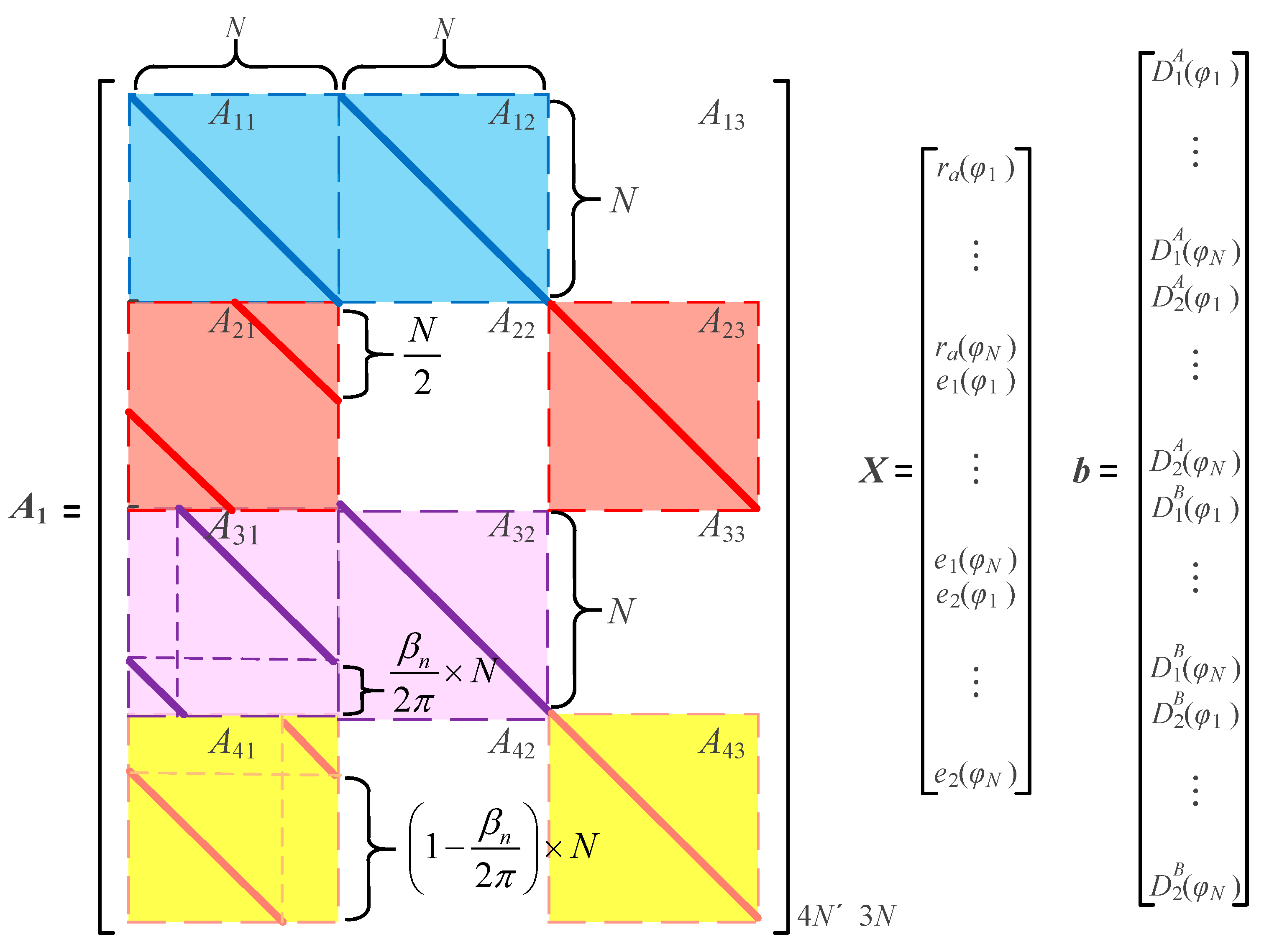
D2 into Equation (16), and each part is shown in
Figure 3.
Vector
b is composed of sensor detection data. The unknown parameters of linear equation
X include the workpiece roundness error
and synchronization motion error
. Coefficient matrix
A1 in
Figure 3 can be denoted as a partitioned matrix:
where
Ek is the identity matrix of
k order;
;
n1 =
βn/2π ×
N,
n2 = (1 −
βn/2π) ×
N,
n3 =
N;
A13,
A22,
A33, and
A42 are zero matrices. O
m is the zero matrix.
The least square method was applied to determine vector
X in Equation (16), one has
The spindle synchronization motion error , , and surface morphology of section a contained in vector X. Similarly, substituting the detection data of sensors D3 and D4 into Equation (18), the vector X, namely the spindle synchronization motion error , , and surface morphology of the workpiece in section b, can also be solved.
Finally, the synchronization motion error obtained for different rotation angles βn can be substituted into Equations (8) and (9) to obtain the tilting error and radial motion error .
4. Simulation Verification
In this section, the accuracy of the proposed method is verified using numerical simulations. Due to the influence of sensor position and spacing on sensor measurement signals, and according to the recommendations in the sensor manual, the installation spacing of sensors D1 and D3 is set to be 50 mm, with the installation spacing of sensors D2 and D4 set identically. The installation position of the sensor was the same as that shown in the detection principle described in the previous section. The distance between sensors D1 and D3 and the reference plane was set as 100 mm.
The morphology of the workpiece
ra(
φi)(
i = 1, 2, …,
N) is generated by a random function rand with
N points uniformly distributed within the interval [
rL,
rU], that is
where
γr is the length of interval.
The synchronous motion error of the spindle will periodically occur with the rotation of the spindle. Therefore, the Fourier series can be used to represent it, and one gets
where
φi is the spindle rotation angle;
Aj is the
j-th harmonic coefficient;
αL is the initial phase angle.
According to Equation (20), the expressions for the radial runout errors
δx,
δy along the
x and
y directions of the spindle and the tilting angle swing errors
εx,
εy around the
x and
y axes can be written as
For the convenience of analysis, the first two orders of the Fourier series were selected, and the simulation parameters for the radial motion error of the spindle are shown in
Table 1.
As shown in
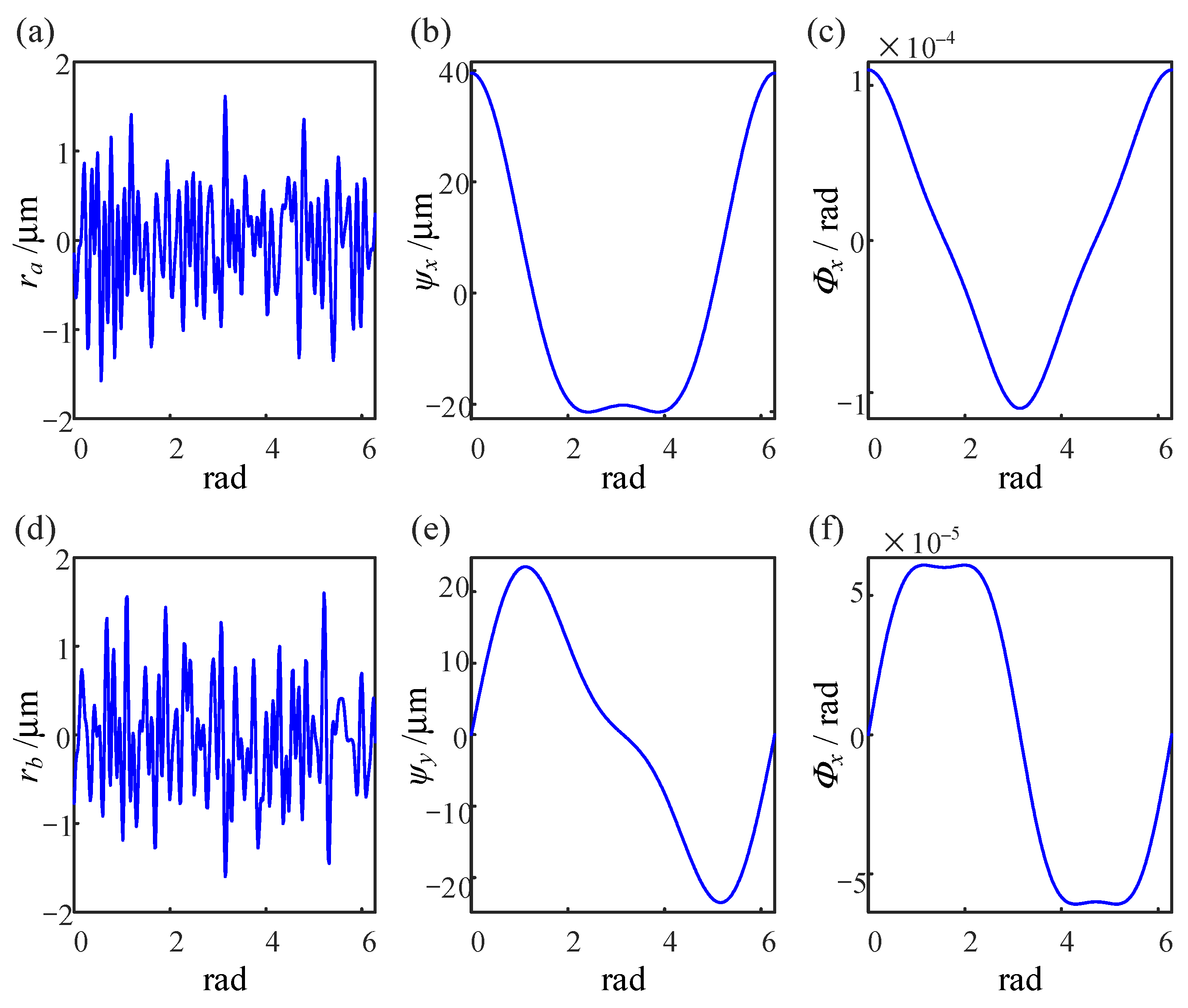
Figure 4, 360 sampling points were taken in one period to construct the surface topography and spindle synchronous motion error of the two sections, among which the synchronous motion error of the spindle included the radial motion and tilting errors.
If
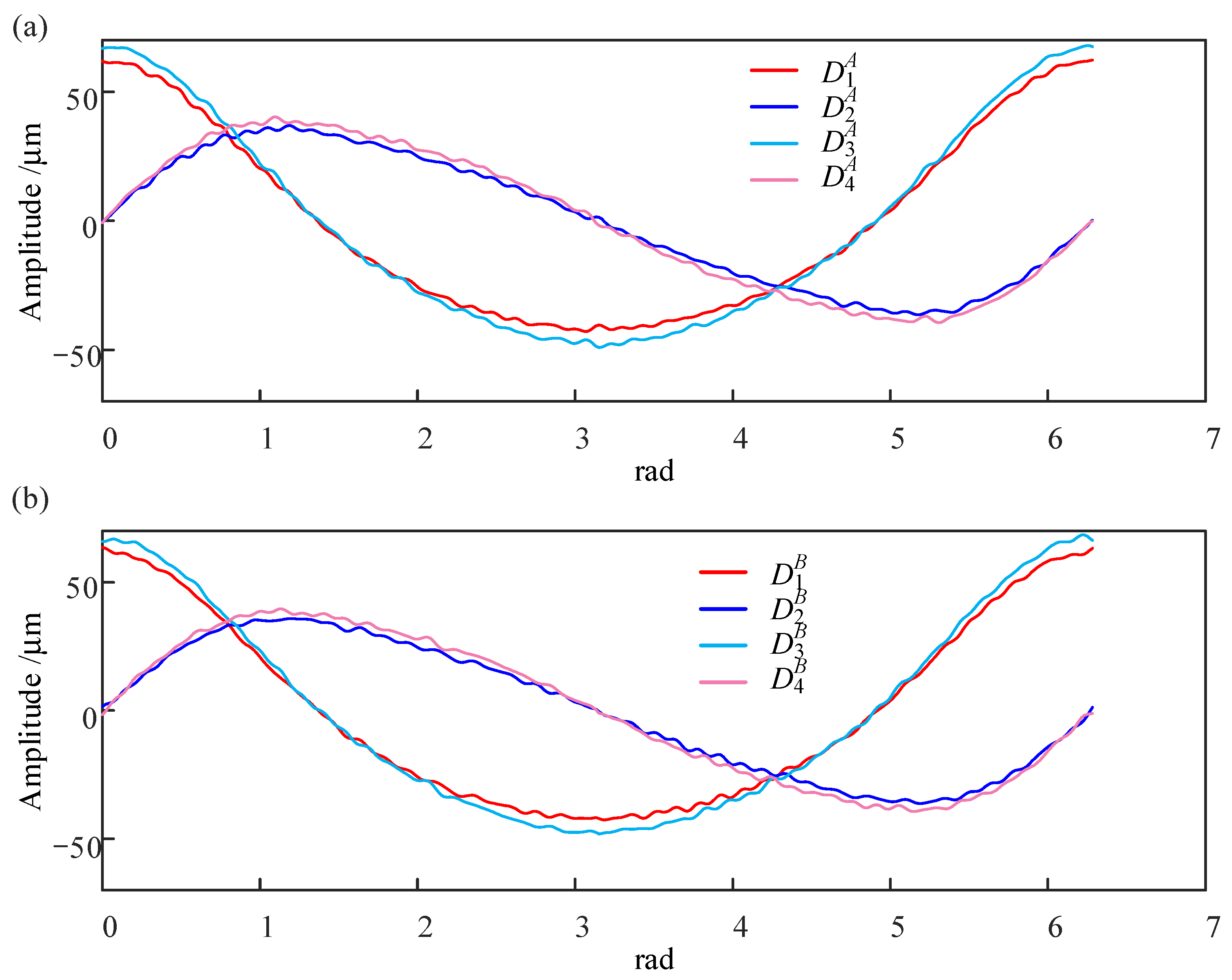
βn = π/2, the theoretical reading of the sensor consists of two parts: spindle motion error and workpiece surface topography. As shown in
Figure 5, The sensor readings before workpiece rotation are
,
,
, and
, The sensor readings after workpiece rotation are
,
,
, and
.
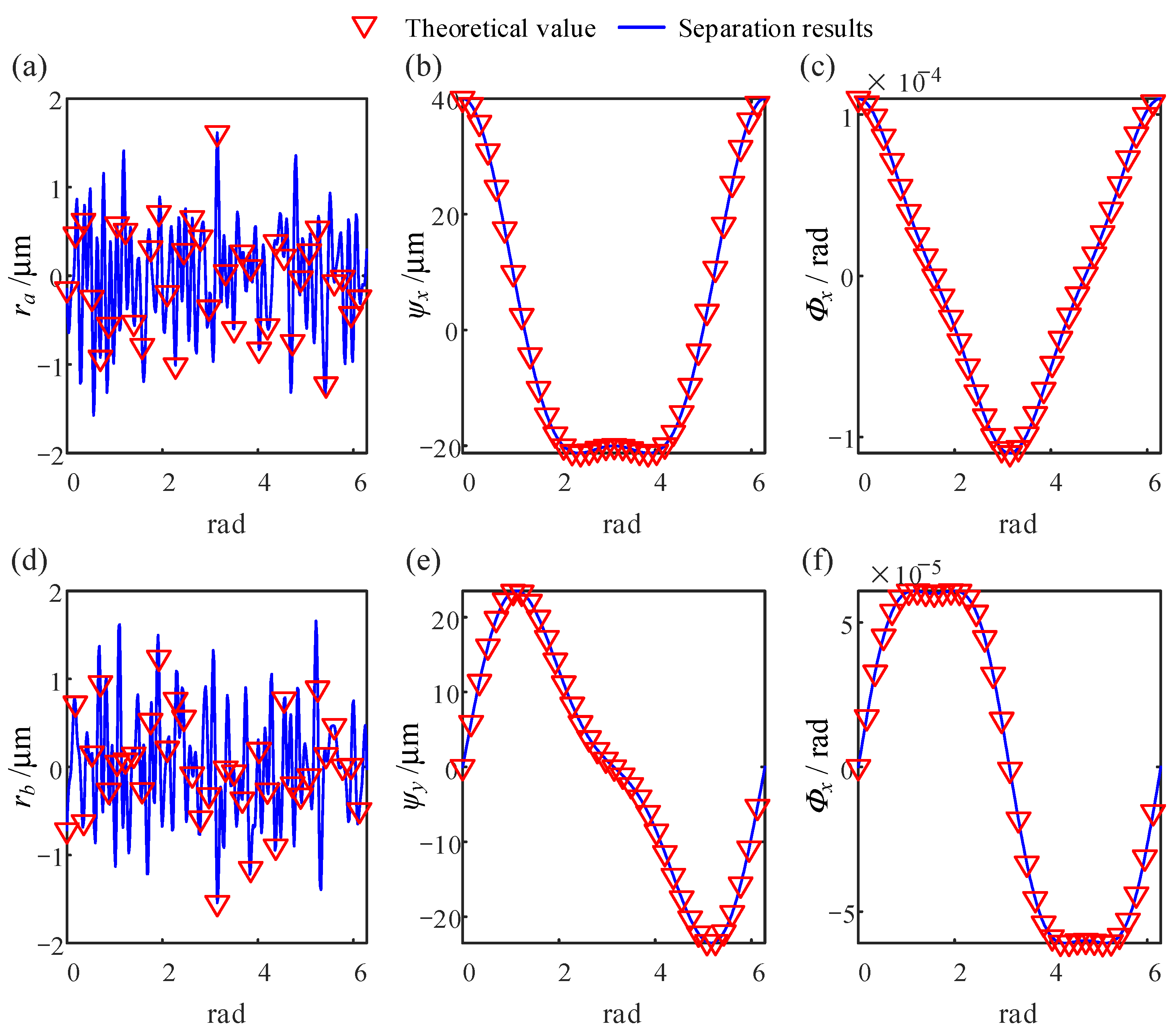
Figure 6 shows a comparison between the theoretical data and separation results. It can be observed that the cross-section surface topography data and spindle motion error data after algorithm processing are consistent with those before processing.
The calculation error between the theoretical and separation values can be evaluated using the mean square error (MSE), mean absolute error (MAE), and the determination coefficient
R2. The MSE can be expressed as
where
Ntol is the total amount of data.
The MAE can be expressed as
The determination coefficient
R2 can be expressed as
where
denotes the sum of squares of the data residuals,
denotes the sum of squares of the total data,
denotes the theoretical data,
denotes the mean value of the separation results, and
denotes the separation results.
The MSE between the separation and theoretical values was 9.2202 × 10⁻¹⁹, with an MAE of 7.2177 × 10⁻¹⁹, determining the coefficient R2 as 1. This indicates the high computational accuracy of the proposed algorithm in separating the spindle synchronization error and the workpiece section topography data from the detection data. In addition, in simulated environments, the method’s calculation time is 0.2 s, marginally longer than the 0.1 s of traditional methods.
In addition, the influence of different workpiece rotation angles
βn on the separation results was studied. The calculation results range from 30° to 330°, with an increment of 30°, for a total of 11 rotation angles, as shown in
Figure 7.
The higher the similarity between the separation result and the theoretical value, the closer the value of
R2 in Equation (24) is to 1. The influence of the different rotation angles on
R2 is shown in
Figure 8.
When β = m × π/2(m = 1, 2, 3), the surface morphology ra(φi) of the workpiece and spindle synchronous motion error en(φi) are completely separated from the detection signal. In other cases, slight computational errors may exist between the separation and theoretical values. The workpiece profile is more sensitive to these numerical errors than the spindle motion error, but the deviations remain within acceptable limits.
In this work, the Weierstrass-Mandelbrot function (W-M) is applied to simulate asynchronous motion errors of the spindle [
33,
34]. Its expression is as follows:
where
G is set to 1 × 10
−4;
Dz is distributed within (1,2);
γ is commonly set to 1.5;
n is the frequency index, and
n1 satisfies
γn1 = 1/
La (
La denotes the sampling length).
In this section, the arithmetic mean deviation
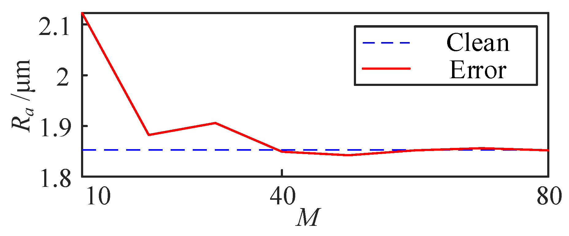
Ra of the simulated profile of workpiece is 1.85 μm, and the
Ra of the asynchronous error is 1.53 μm. The effect of spindle asynchronous error motion on the workpiece cross-section
Ra is shown in
Figure 9. As the number of periods
M increases, the
Ra value of the workpiece section with asynchronous error gradually approaches the theoretical value of the workpiece section without asynchronous error.
Separation results show that the proposed algorithm achieves high computational accuracy when solving synchronous, asynchronous, and workpiece topography data. The synchronous motion error of the spindle has little effect on the surface morphology of the workpiece. Asynchronous errors can be reduced in its impact on separation results by increasing the number of work periods.
The circular cross-section shape of the rotating workpiece exhibits deterministic periodic signal characteristics. The Fourier series expansion equation of cylindrical workpieces is as follows [
35]:
where
θ denotes the polar angle;
Z is the axial coordinate system;
r0 is the average radius of the circle cross-section of the workpiece;
k denotes the harmonic number;
ak and
bk are the Fourier series of roundness error profiles.
The mean radius of the workpiece
r0 is 30 mm during the simulation and the Fourier harmonics coefficients
ak and
bk are listed in
Table 2.
The theoretical profiles of the workpiece are shown in
Figure 10a.
Figure 10b–d shows the projection of the cylindrical outline in three directions. The spindle synchronization error is consistent with the simulations in the previous section. The cross-section data and motion error data were combined to form the sensor simulation reading. The cylindrical cross-section data are then separated from the sensor signals using the method proposed in this study.
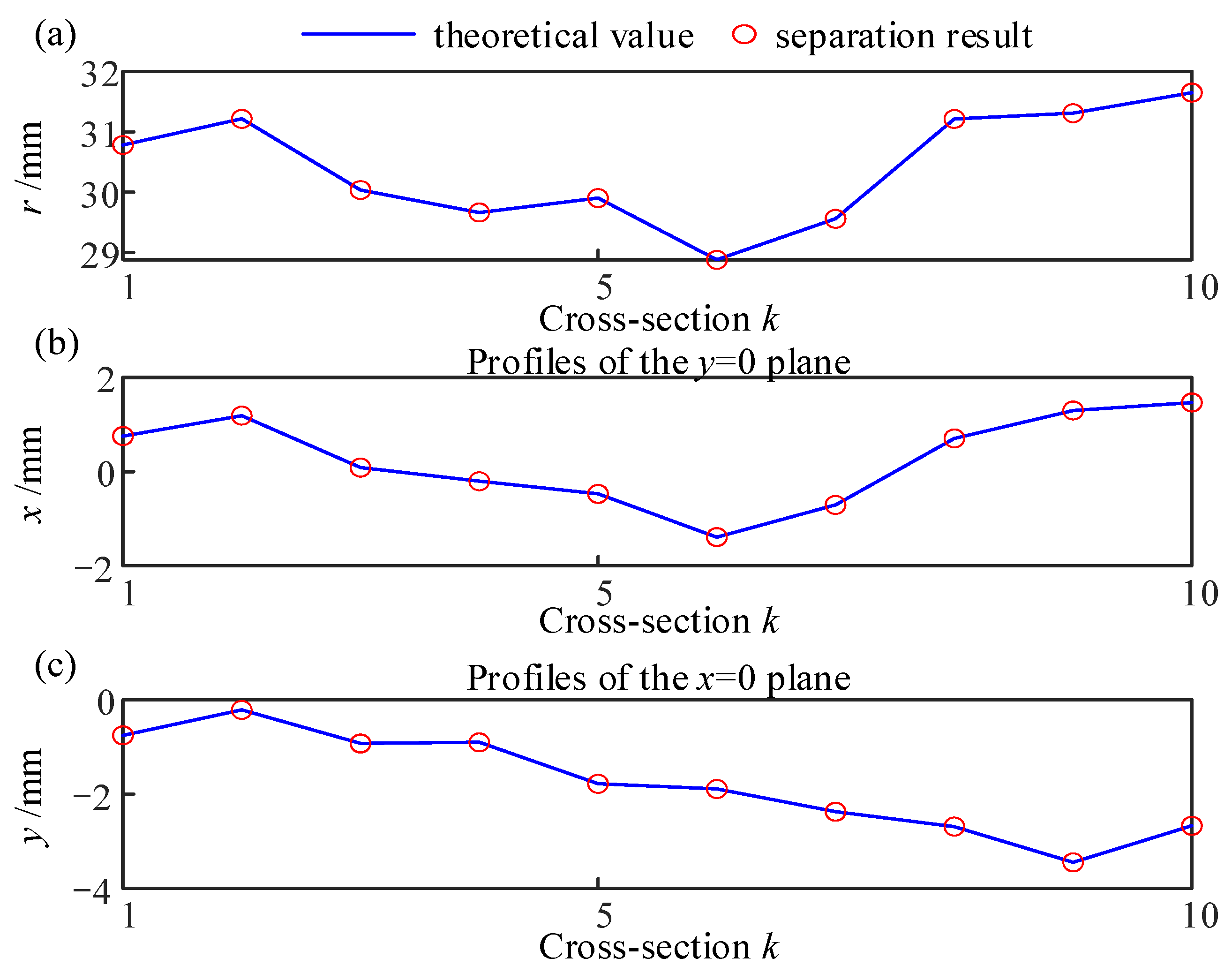
A comparison between the theoretical and separation results of the line connecting the profile of the busbar and the center of the cross-section is shown in
Figure 11. The effect of the spindle synchronization error on the detection results of the cylindrical busbar is very small.
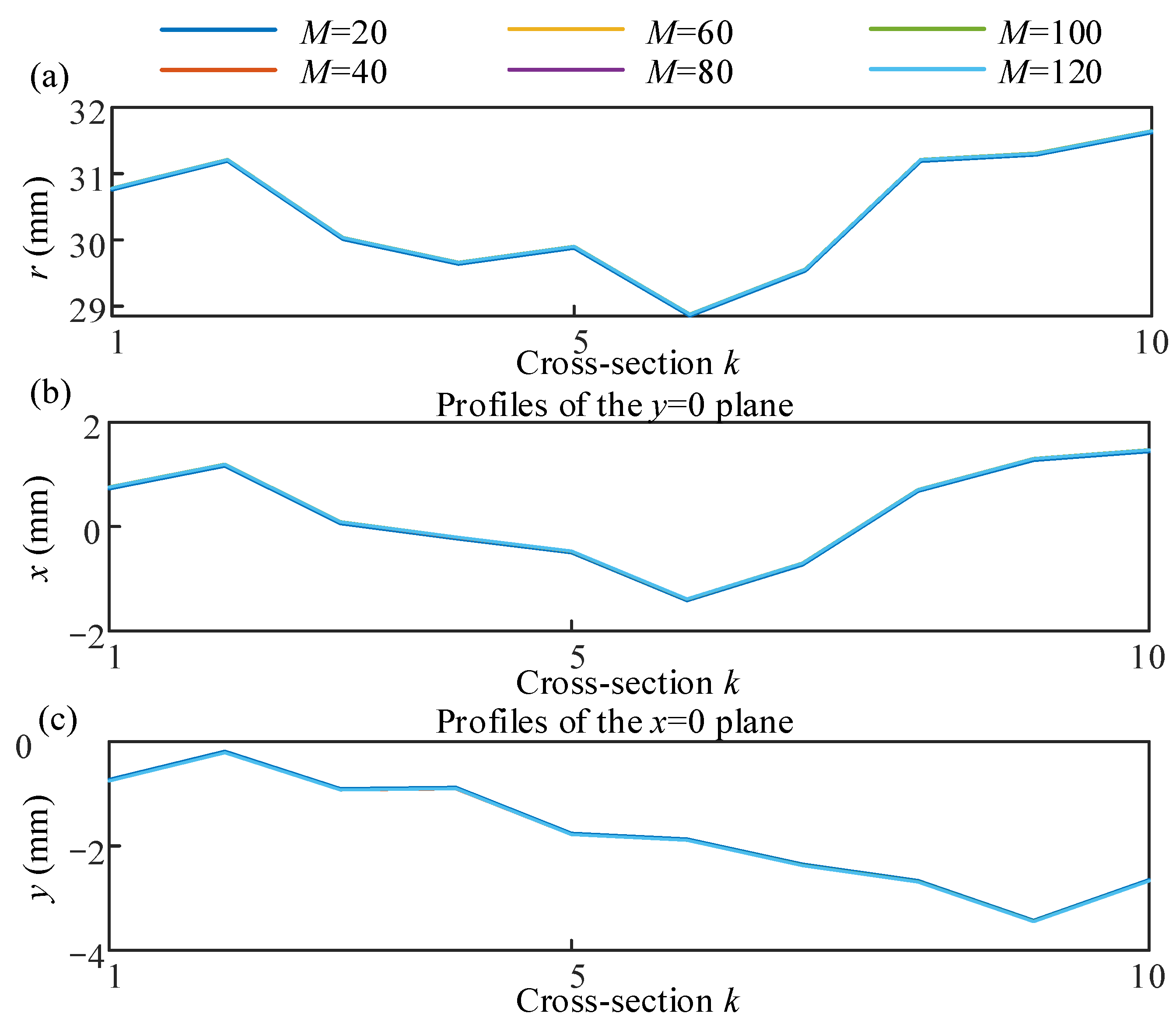
The spindle asynchronous error is consistent with that described above. Increasing the number of periods of the spindle can neutralize the asynchronous error. The variation in spindle asynchronous error with the
M in the workpiece cross-section profile is shown in
Figure 12. The axis straightness and cylindricity of the simulated cylindrical workpiece are 3.3723 mm and 0.1576 mm, respectively. As the periods
M increases, the impact of the spindle asynchronous error on cylindricity and straightness decreases, as shown in
Table 3.
5. Experimental Results and Discussion
In this section, an experimental study was conducted to confirm the effectiveness of the proposed detection method in this work. A detection platform was set up, and multiple sets of cross-sectional data of the workpiece were collected during spindle operation. Furthermore, an experiment was conducted to separate the spindle motion error and workpiece surface morphology under different rotation angles has been completed.
As shown in
Figure 13, the experimental platform built in this work comprises a CNC6130 (Yingtai Machine Tool, Wenling, China) and four eddy current displacement sensors (ML-02-00-03, MIRAN, Shenzhen, China, with an uncertainty of 0.0015 mm). Sensors
D1 and
D2 detect section
a of the workpiece, while
D3 and
D4 detect section
b.
D1 and
D3 detect the displacement signal in the
y direction, while
D2 and
D4 detect the dis-placement signal in the
x direction. The four sensors simultaneously detect the displacement signals of the two cross-sections of the workpiece, and the initial phase of the detection is marked on the end face of the workpiece.
5.1. Experimental Results
During the experiment, the center of the initial detection section
a is 200 mm away from the spindle center and 50 mm away from section
b. These two sets of spatially orthogonal sensors detect displacement signals in the
x and
y directions of cross-sections
a and
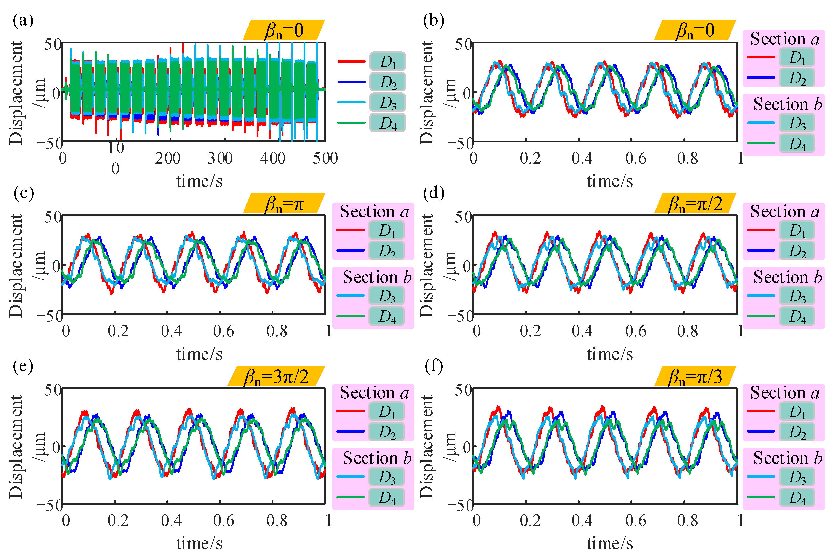
b. The spindle speed of the CNC machine tool is set to 300 r/min, and the worktable moved 1 mm along the axis every 10s to collect multiple data sets. The detection results at different rotation angles
βn are shown in
Figure 14.
First, in the data-preprocessing process, it is necessary to filter the experimental data and truncate high-frequency noise, which is tens of times higher than the spindle operating frequency. After filtering was completed, the unstable data after the spindle was turned on and before the spindle was turned off were removed to avoid the effect of the spindle working instability on the data processing. The displacement signal exhibited periodicity. When the sampling frequency is determined, the detection data are grouped based on the signal length of the number of sampling points within one period of the spindle work. Subsequently, data with the same phase were averaged to offset the asynchronous error of the spindle. Finally, the detection signal includes only the synchronization motion error of the spindle and the surface morphology of the workpiece profile.
The proposed method is applied to separate the surface morphology and spindle motion error of the workpiece from the detection data.
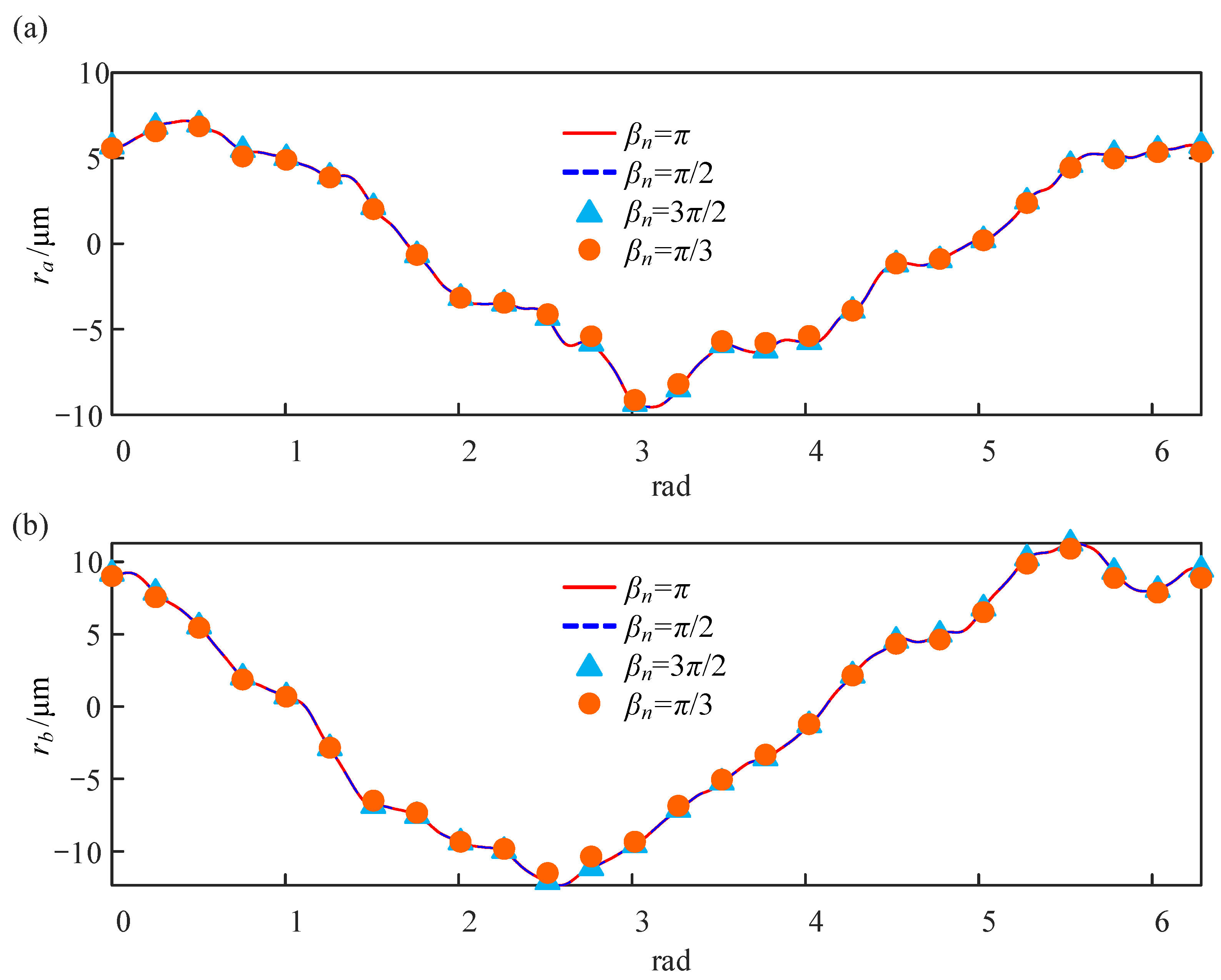
Figure 15 shows the surface morphology of the first two detection parts of the workpiece at different rotation angles
βn. The morphology of the two profiles was consistent. The arithmetic mean deviation
Ra of the profile for sections
a and
b at different rotation angles
βn are listed in
Table 4.
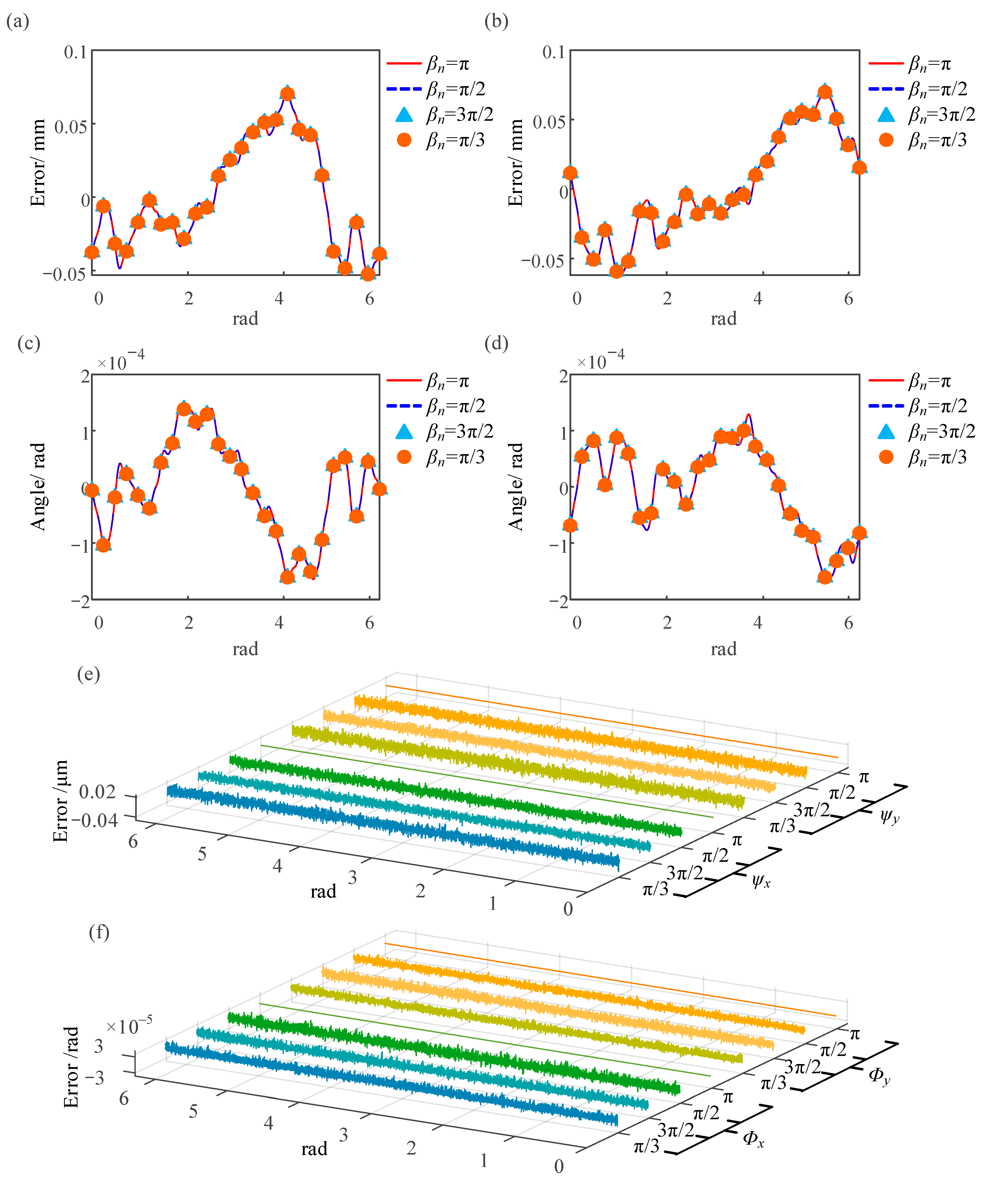
In addition to the surface morphology of the workpiece, the radial motion and the tilt oscillation errors of the spindle at different rotation angles
βn are shown in
Figure 16. During turning, the motion error of the spindle affects the roundness, cylindricity, and coaxial errors of the workpiece. Owing to the phase difference between the spindle tilting error and radial motion error, a portion of the spindle radial motion error is neutralized by the spindle tilting error. Although this phenomenon reduces the amplitude of the spindle synchronization error within a certain length, as the machining surface of the workpiece gradually moves away from the reference plane, the influence of the spindle tilting error on the form error of long-shaft workpieces becomes increasingly significant. The reason for the displacement detection data increase with the distance between the detection section and the chuck is also the same.
To verify the accuracy of the proposed method, the proposed method in this study was used to obtain detection results with rotation angles of π/2 and 3π/2 and compared with the detection results obtained by the reversion method. When the rotation angle was π/3, the calculation error of the spindle motion error was within 1%, whereas the calculation error of the workpiece morphology was within 5%. The results obtained from experimental study are consistent with those obtained from simulation study. This indicates that the experimental results verify the accuracy and reliability of the method.
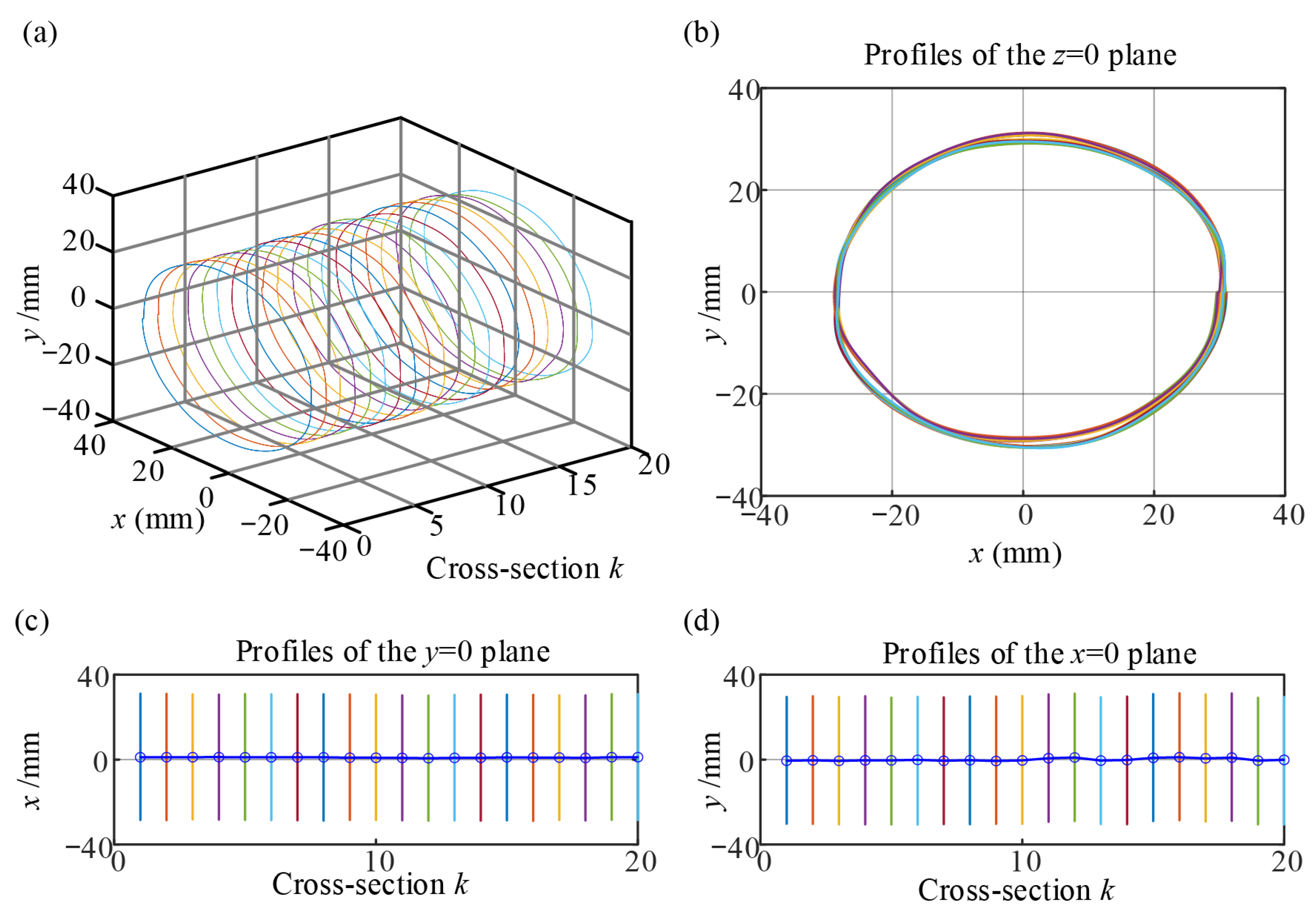
Next, a three-dimensional morphology of the workpiece is obtained by using a plurality of section information of the workpiece. The separation method proposed in this study was applied to obtain surface morphology data from multiple cross-sections. The average radius of the workpiece is 30 mm, and the 3D surface morphology of the workpiece is reconstructed based on the position of the cross-section, as shown in
Figure 17a.
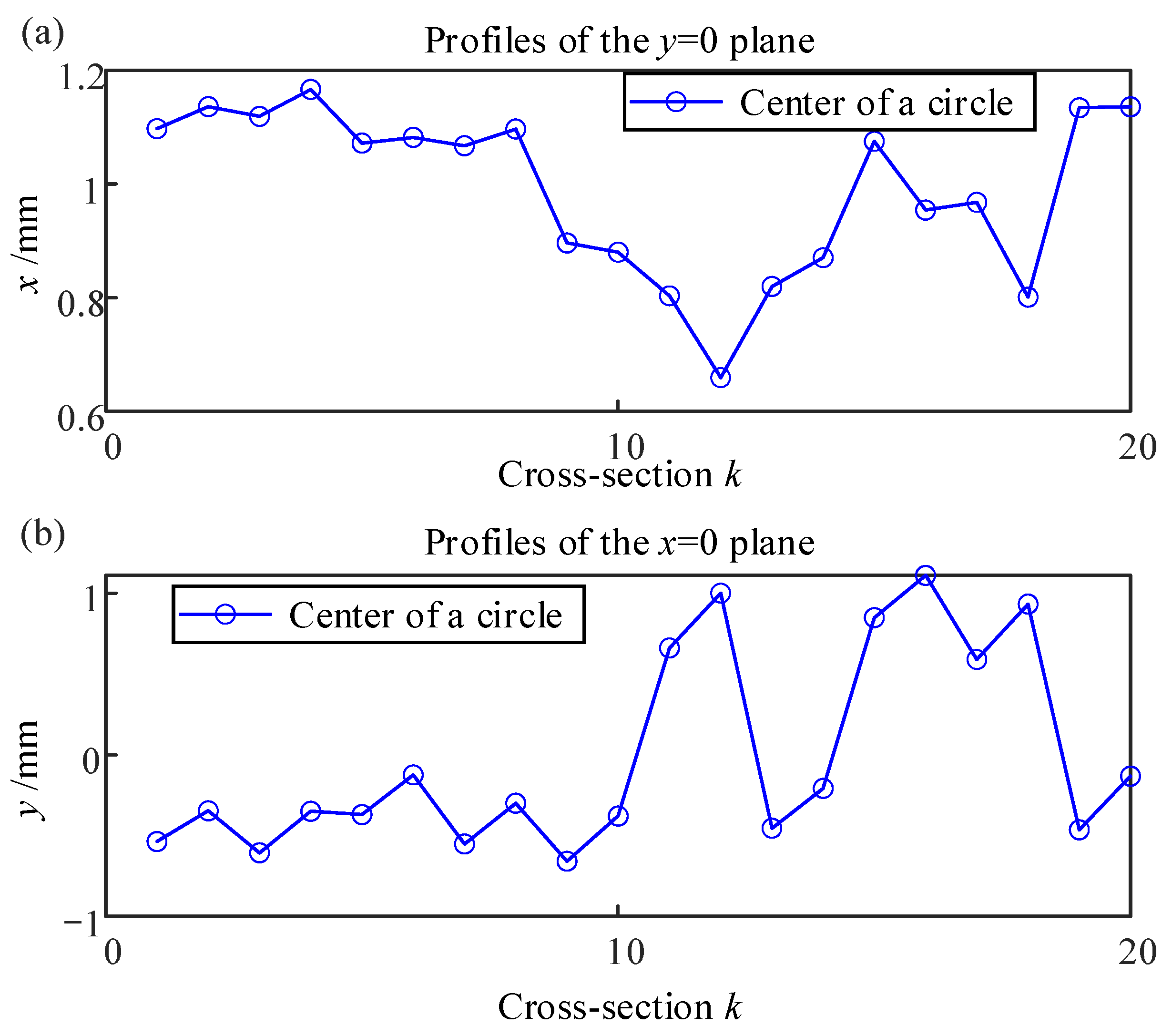
Figure 17b–d shows the projection of a cylindrical contour in three directions. The projection of the center of the cross-section of the cylindrical workpiece in the
x and
y directions is shown in
Figure 18. The axial straightness and cylindricity errors for the cylindrical workpieces are 2.7371 mm and 1.5832 mm, respectively. Next, it is also necessary to analyze the influence of asynchronous error and sensor error on the detection results.
5.2. Error Analysis
In this section, the influence of asynchronous error and sensor error on workpiece shape error obtained by the method proposed in this work is studied.
5.2.1. Effects of Asynchronous Error on Identification Results
During the collection of spindle motion errors, asynchronous errors always exist. As the spindle rotation period
M increases, some asynchronous errors are neutralized, but asynchronous errors cannot be eliminated. The effect of the asynchronous error on the
Ra for profiles of the same section is presented in
Table 5. The results indicate that as the working period
M increases, the impact of asynchronous errors gradually decreases.
5.2.2. Sensor Noise
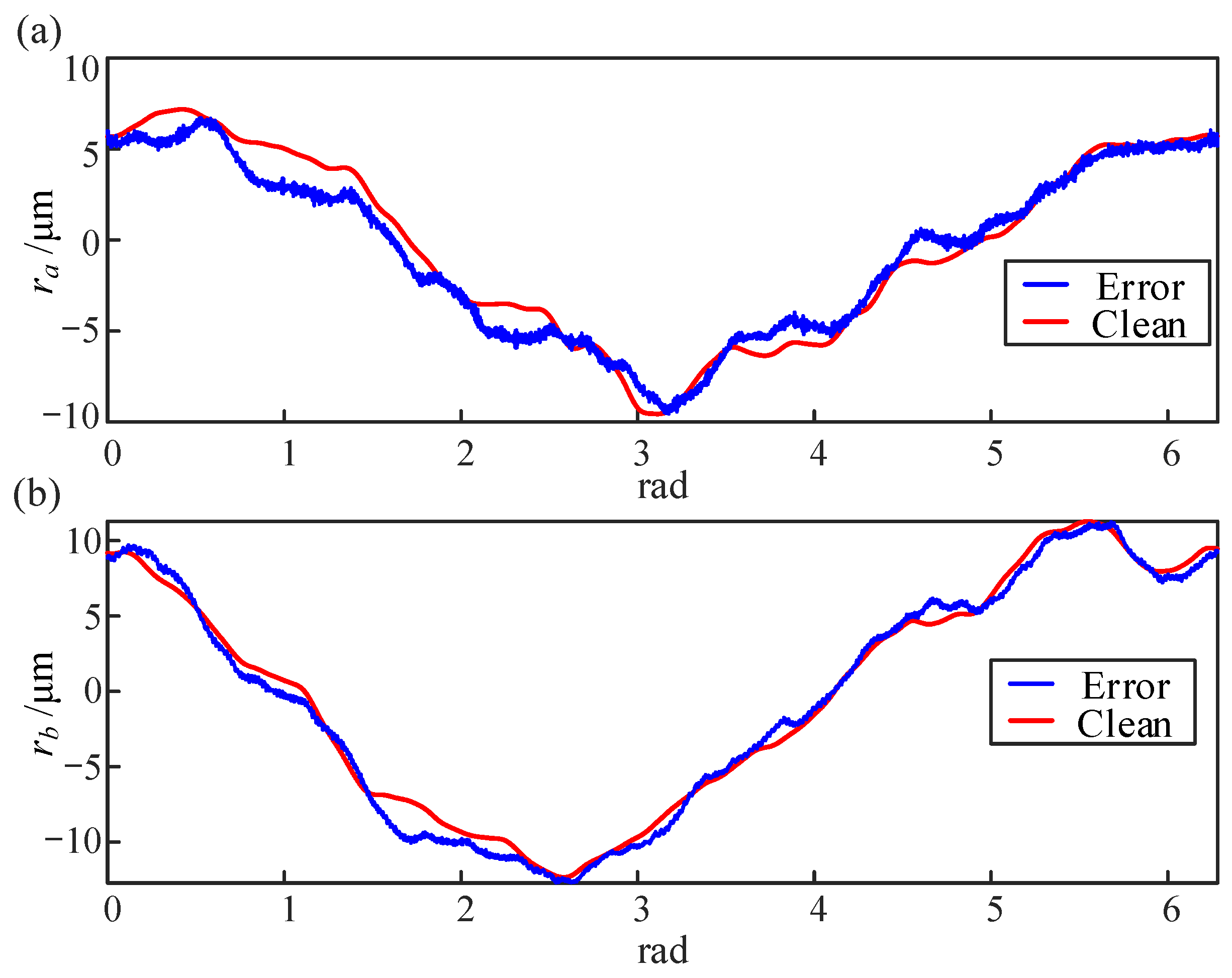
The experimental results before and after removing the high-frequency noise from the sensor are shown in
Figure 19. During the experiment, the detection data are affected by high-frequency noise from the sensor. During data preprocessing, it is necessary to filter the detection data with a cutoff frequency of 500 Hz. The impact of the high-frequency noise from sensors on the evaluation indicators of the workpiece surface quality is shown in
Table 6.
5.2.3. Sensor Installation Angle Error
In this section, the impact of sensor installation angle error on measurement results is analyzed. Assuming that sensor
D1 is not parallel to the
x-axis, there exists an angle of magnitude
Δ. As shown in
Table 7, the larger the angle, the larger the
Ra of the measured cross-sectional profile, and the straightness and cylindricity errors also increase. During the experiment, it is essential to ensure that the sensor’s axis is parallel to the coordinate axis.
5.2.4. Sensor Reading Phase Error
In this section, the impact of sensor reading phase error on measurement results is analyzed. Assuming that sensor
D1 is arranged along the
x-axis and sensor
D2 is arranged along the
y-axis of the tested section, the sensor position is parallel to but not coincident with the coordinate axis, resulting in a phase difference of ∧. The impact of phase difference on
Ra, straightness error, and cylindricity error is shown in
Table 8.
5.2.5. Index Angle Error
In this section, the influence of index angle errors of 0°, 1°, and 2° on the arithmetic mean deviation and straightness value of section
a during the rotation process of the workpiece was studied when the rotation angle was taken as different values. The impact of index angle error on the calculation results at spindle speed of 300 r/min is shown in
Table 9.
5.3. Applicability and Prospect
This section comprehensively evaluates the engineering value and improvement space of the proposed method in this work through comparison with the existing methods, analysis of applicable scenarios, and discussion of constraints.
Table 10 summarizes the comparison between the proposed method and the existing method.
The method proposed in this work has some applicability in the following aspects:
- (1)
The sensor type is not limited to eddy current, and laser or capacitor can apply the same mathematical framework.
- (2)
It can be transplanted to grinding machines, turbine scroll shafts, and other rotating machinery.
- (3)
The proposed method uses minimum sensor settings (4 eddy current sensors) and simple data processing, reducing hardware and maintenance costs.
There are still some defects or omissions in this work, and subsequent studies can still be carried out in the following aspects:
- (1)
The current experiment mainly focuses on the low speed, and the sensor bandwidth and dynamic calibration still need to be verified under the ultra-high speed (>10,000 r/min).
- (2)
Both the simulation and test artifacts are cylindrical and other complex shapes can be investigated later.

