Abstract
In this paper, we propose a dual-loop Active Disturbance Rejection Control (ADRC) strategy for gust load alleviation in flexible aircraft. By decoupling the control of modal and normal accelerations and spatially allocating control surfaces, the method effectively resolves signal interference. Simulation results show that compared to the uncontrolled case, the ADRC controller reduces the wing root bending moment peak by 38%, the normal load factor peak by 32%, and the pitch angle fluctuation by 38%. Robustness tests under actuator delays (4 Δt and 8 Δt) and gain perturbations (−50% and +100%) further confirm that the system maintains time-domain stability and effective load mitigation across varying conditions. These results demonstrate that the proposed ADRC scheme not only improves load suppression but also offers strong robustness against parameter uncertainty, providing theoretical and practical support for next-generation active control systems in aeroelastic environments.
1. Introduction
With the increasing demand for higher cruise efficiency and economy in modern, large transport aircraft, high-aspect ratio wings have emerged as a primary design approach to enhance the lift-to-drag ratio. However, the larger structural flexibility of these wings, while improving lift, also results in greater structural sensitivity. This is especially evident when the aircraft encounters gusts, which lead to significant variations in wing root loads and excitation of the wing’s bending modes, severely affecting flight performance and accelerating structural fatigue. Therefore, gust load alleviation (GLA) technology has become one of the key challenges in the design of flexible aircraft.
Gust loads can be reduced by passive and active gust load alleviation (GLA) systems. In passive GLA systems, the wing is designed to deform under increased loads such that the gust loads decrease. Active GLA systems are control systems that determine the loads with sensors and reduce the gust loads by controlling actuators. In active GLA systems, there is the conceptual difference of feedforward control based on a predictive sensor [1,2,3], feedback control based on local sensors on the airplane [4,5,6], or combinations of both [7,8]. The advantage of feedforward controllers with predictive sensors is that the actuators and evasive pitch controllers have a little more time to react to the gust.
In recent years, Active Disturbance Rejection Control (ADRC) has gained widespread attention in flexible aircraft control due to its inherent robustness against system modeling errors and external disturbances through real-time total disturbance estimation and compensation [9,10,11]. While ADRC’s core strength lies in its model-agnostic disturbance rejection capability, this study extends its application to multi-objective gust load alleviation (GLA) by proposing a dedicated dual-channel framework. However, traditional GLA control laws, often employed in flexible aircraft, suffer from significant limitations, such as difficulty in effectively handling conflicting control objectives. In [12], a linear quadratic regulator is augmented with model reference adaptive control. This design is also based on a linear system. With the model predictive controller in [13], only a moderate reduction in the gust loads was achieved. For example, when controlling structural oscillations (modal response) and normal acceleration (), the control signals may conflict, leading to system oscillation or instability, especially in shared control surface systems. This issue highlights the need for a more robust and decoupled control strategy in GLA systems.
In this study, we propose a multi-objective ADRC framework with control surface allocation to decouple structural responses and acceleration control. The dual-channel ADRC controllers are designed for modal acceleration and normal acceleration, with the spatial allocation strategy exploiting differential aerodynamic effectiveness: inner control surfaces (closer to the wing root) primarily regulate normal acceleration through direct lift control, while outer control surfaces (near the wingtip) preferentially dampen structural modes due to their higher moment arm about elastic axes. This physical decoupling prevents control signal conflicts.
2. Control Law Design for Gust Alleviation
2.1. Aircraft Platform Description
This study uses the SE2A aircraft model as the reference, which was developed based on the SE2A open-source model described in [14]. The aircraft’s information and external configuration are shown in Figure 1.
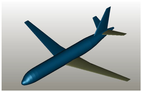
Figure 1.
SE2A model.
The primary physical properties of the research aircraft are listed in Table 1. These include reference area, mass, and moments of inertia, which are essential for both aerodynamic modeling and controller design.

Table 1.
General properties of the research aircraft.
Modal frequencies refer to the natural frequencies at which an aircraft’s structure vibrates in response to external disturbances. In this study, the modal frequencies are used to describe the natural vibration modes of the aircraft, which significantly influence its response to gust loads. For flexible-wing aircraft, these modal frequencies and their contributions to the wing root bending moment (WRBM) are key factors affecting structural integrity.
Table 2 summarizes the dominant structural modes and their characteristics for the SE2A flexible-wing aircraft, based on high-fidelity aeroelastic simulations. Key parameters include the following:

Table 2.
Dominant structural modes of SE2A flexible-wing aircraft.
- Modal frequencies (rad/s) of critical symmetric modes;
- Contribution percentages to the wing root bending moment (WRBM) under gust loads.
The first bending mode (Mode 1 at 9.84 rad/s) dominates both static and dynamic WRBM with an 84% contribution, while the second bending mode (Mode 7 at 29.8 rad/s) accounts for 14%. Torsional and bending–torsion coupling modes (Modes 3 and 5) show negligible WRBM influence (<1%) but exhibit unique engine oscillation behaviors.
2.2. Aircraft Sensor Distribution
Historically, aircraft primarily relied on pitot tubes for atmospheric data acquisition. With the development of radar technology and microelectromechanical systems (MEMSs), measuring gusts and sensing their impact on the aircraft has become far less challenging. The gust alleviation sensor layout for a particular commercial airliner is shown in Figure 2.
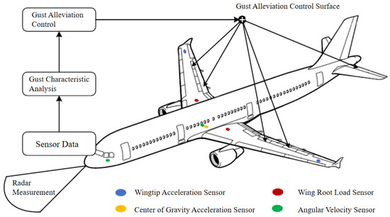
Figure 2.
Onboard sensor layout of the aircraft.
The basic principle by which the aircraft uses lidar to detect gusts is as follows: A short-pulse laser is emitted forward from the fuselage, illuminating a specific region ahead of the aircraft (typically 60–300 m). As the pulse propagates through the air, a small fraction of its energy is scattered back to the lidar sensor. By comparing the frequency of the back-scattered light with that of the transmitted pulse, the system can derive predictive atmospheric data [15]. Because radar sensing acquires these disturbance parameters before they reach the wing and load the structure, the gust alleviation system can forecast impending loads and counteract them preemptively.
In this study, the objective of gust load alleviation is primarily to reduce aircraft normal load factor and wing root bending moment. Accordingly, accelerometers are installed at the center of gravity (CG) to measure the normal acceleration (i.e., load factor); angular-rate sensors are placed at the nose and the CG to measure the aircraft’s instantaneous angular rates, which are crucial for rigid-body motion estimation; load sensors are mounted in each wing root to measure local bending moments; and accelerometers are installed at each wingtip to record tip accelerations. Section 2.1 describes how Mode 1 contributes dominantly to the aircraft’s wing root bending moment (WRBM). We can combine the wingtip acceleration data with known mode-shape information to estimate the modal response. Specifically, the measured tip acceleration is treated as a superposition of multiple modal vibrations; by projecting this signal onto the seventh-mode shape, we extract its contribution and thereby recover the seventh-mode acceleration time history.
Beyer et al. [14] proposed a high-fidelity flexible-wing simulation model that uses the inboard and outboard flaps as load alleviation control surfaces. In this model, the wing is divided into 40 spanwise strips: the five inboard strips on each side serve as inboard flaps, and the ten adjacent strips serve as outboard flaps. Since the outboard flaps have a larger effect on the wing root bending moment, our control strategy is to use the inboard flaps to regulate normal acceleration, while the outboard flaps suppress structural-mode responses.
2.3. Structure and Design Principles of the Controller
In the gust-disturbed environment of a flexible aircraft, structural modal oscillations and the fuselage’s normal acceleration response represent two fundamentally different control objectives: the former is a localized, high-frequency flexible response, while the latter reflects the low-frequency rigid-body acceleration of the entire airframe. These two dynamics differ markedly in their frequency characteristics, disturbance sources, and control requirements. Attempting to regulate both with a single controller gives rise to three major problems:
- (1)
- The control directions for each objective on a given control surface may oppose each other, leading to signal conflicts or even actuator chatter;
- (2)
- The disparity in dynamic bandwidth between modal vibrations and normal acceleration makes it impossible to satisfy both channels’ response requirements with a single set of control parameters;
- (3)
- Forcing a unified observer structure for two distinct disturbance measurement sources (structural sensors vs. inertial measurements) degrades the extended-state observer’s accuracy in estimating total disturbances.
To address this, we design two independent ADRC loops:
Structural Modal Control: its objective is , i.e., to drive the structural modal acceleration of the wing’s primary mode to zero, thereby canceling the inertial loads that produce the majority of the wing root bending moment under a gust.
Normal Acceleration Control: its objective is , i.e., to hold the normal acceleration at the level of gravity so that net “felt” acceleration on the fuselage is zero, improving passenger comfort and reducing transient load spikes.
These controllers are structurally independent—each with their own observer and gain tuning—and their outputs are allocated to different regions of the control surfaces via a surface allocation strategy, achieving true decoupled load-and-ride control in both effect and implementation.
Based on this analysis, two independent active disturbance rejection controllers are designed: one observes modal accelerations and focuses on the rapid damping of structural oscillations; the other uses normal acceleration as its feedback variable to enhance flight quality and mitigate short-period load spikes. These controllers are structurally independent, with their control laws and observer parameters tuned separately, and their outputs are distributed to different regions of the control surfaces via a surface allocation strategy—thus achieving true decoupled control both in effect and physical implementation.
Figure 3 illustrates the overall structure of the dual-channel ADRC-based gust load alleviation system. The upper control loop corresponds to the normal acceleration control, in which the control objective is to maintain , thereby suppressing short-period load spikes and improving passenger comfort. The lower loop corresponds to the structural modal control, targeting to mitigate flexible mode excitations and reduce wing root bending moments.
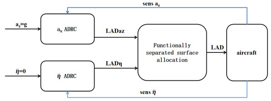
Figure 3.
Block diagram of the aircraft gust load alleviation controller.
Each ADRC loop generates a load alleviation demand signal:
- is the control signal output from the -channel ADRC controller, which is assigned to the inboard trailing-edge flaps of the wing;
- is the control signal output from the modal ADRC controller, allocated to the outboard trailing-edge flaps.
These two signals are combined in a functionally separated surface allocation module, which maps them onto distinct control surface regions to prevent conflict and interference. Sensor feedback from and is used to close the loop independently for each controller, ensuring robust decoupled load alleviation performance.
2.3.1. Normal Acceleration Control
In gust load alleviation control, the controlled variable is defined as the normal load factor, and the aircraft regulates the normal load factor to maintain a desired level (typically 1 g) and minimize load response in gusts to maintain a low load response in gusts.
In the equations, denotes the aircraft’s normal load factor; V denotes the true airspeed; and denotes the flight path angle.
At the same time, the pitch angle (), angle of attack (), and flight path angle of the aircraft have the following relationship:
Taking the derivative yields . At this point, can be approximated as q, and thus
From the short-period approximate equations, we obtain the following:
where ,, represents the uncertainty estimate of gust load response; is the vector of control surface deflections; and is the control effectiveness vector mapping these deflections to normal force changes. Here, represents the deflections of the aircraft’s flaps () and elevator ().
By differentiating Equation (4), we obtain the following:
The aerodynamic parameters of the aircraft in a gust can change dramatically, especially the term associated with the angle of attack.
In this architecture, the elevator serves as the primary actuator for attitude control (e.g., pitch trim, flight path stabilization), while gust load alleviation is handled by the flaps. To prevent conflicts between these two loops and decouple their objectives, we treat the elevator’s effect on the normal force as an external disturbance—allowing the gust alleviation loop to focus solely on flap deflections. Therefore, Equation (5) can be rewritten as follows:
The sensors on the aircraft can detect changes in the normal acceleration Az, but the value of the disturbance is difficult to measure. Therefore, it is necessary to construct an extended state observer (ESO) to estimate the total disturbance .
The structure of the ESO is as follows [16]:
where , is the estimate of the system output ; is the estimate of the total disturbance term ; , are the observer gain parameters; and is a nonlinear function, defined as follows:
Based on the results of the ESO, the controller constructs the following feedback control law:
The calculated physically represents the angular rate of the spoiler, and integration is required to obtain the spoiler deflection command. This structure enables real-time compensation for the total disturbance, significantly enhancing the system’s robustness and stability against gust-induced disturbances.
According to the theoretical proof provided in [9,12], when the system disturbance is continuous and bounded, the disturbance estimation algorithm constructed by the ESO can achieve ultimate bounded convergence. In the designed normal acceleration control channel of this study, the total system disturbance includes aerodynamic parameter variations caused by changes in flight conditions, changes in the effectiveness of the elevator, and gust excitations. During flight, the variation in aerodynamic parameters is continuous and bounded, the effectiveness coefficient of the elevator also varies continuously and remains bounded with deflection, and gust excitations are modeled as external disturbances with finite energy, so their amplitudes are also bounded. Therefore, the disturbance satisfies the continuity and boundedness condition, thus meeting the theoretical requirements for ESO convergence.
2.3.2. Structural Modal Control
To achieve suppression of the first-order modal response of the wing structure, it is necessary to establish a controllable modal model for the dynamic behavior of the flexible structure. The structural modal response generally follows the standard dynamic equation for a multi-degree-of-freedom system:
where represents the generalized modal coordinates of the structure; , , and are the modal mass, damping, and stiffness matrices, respectively; and denotes the generalized external force corresponding to the modal response. These forces mainly include the following:
- Non-stationary aerodynamic effects caused by structural deformation;
- Additional aerodynamic loads induced by rigid-body motions (such as changes in angle of attack and pitch rate);
- Direct excitation from local airflow acting on the surface affected by gusts;
- Control aerodynamic forces and disturbances generated by control surfaces (e.g., ailerons).
By combining the above excitations, the generalized external force can be expressed as follows:
where represents various non-stationary aerodynamic excitations (commonly referred to as external disturbances) and is the effective control input projected onto the modal direction by control surfaces.
By substituting this expression into the structural dynamic equation and multiplying both sides by , the modal state–space equation of the system can be obtained as follows:
Let
Further, the standard form of the robust control law can be derived as follows:
To enhance the robustness of the system against soft dynamics, this study adopts a second-order nonlinear extended state observer (ESO) structure within the Active Disturbance Rejection Control (ADRC) design framework. Since the modal dynamics given in Equation (16) are second-order, a first-order ESO—as used in the normal acceleration control loop—is insufficient. Therefore, the modal control path applies a three-dimensional ESO, which estimates the modal displacement , its velocity , and the total disturbance in real time. The updated ESO equations are formulated as follows:
where , , and are the estimated total disturbance. This ESO structure is consistent with the system’s second-order dynamic nature and provides a model-free framework for disturbance estimation.
The control law in the modal acceleration control path is derived based on a disturbance-compensated feedback structure. Specifically, the control objective is to drive the modal acceleration to zero. The reference value is thus defined as , leading to the following form:
where is directly measured through structural acceleration sensors. The first term ensures proportional feedback control based on actual modal acceleration, while the second term provides feedforward disturbance compensation using the ESO estimate. This structure ensures both the fast damping of structural oscillations and robustness to unmodeled dynamic uncertainties.
In consideration of this [17], the nonlinear extended state observer constructed in this study shows the most consistent disturbance estimation across different models, ensuring that the control system remains stable under varying conditions.
3. Results and Discussion
The 1-Cosine discrete gust is considered a relatively dangerous scenario. In this study, the reference gust speed at an altitude of 6000 m is set to 17 m/s. The gust begins to affect the aircraft after 5 s, as shown in Figure 4.
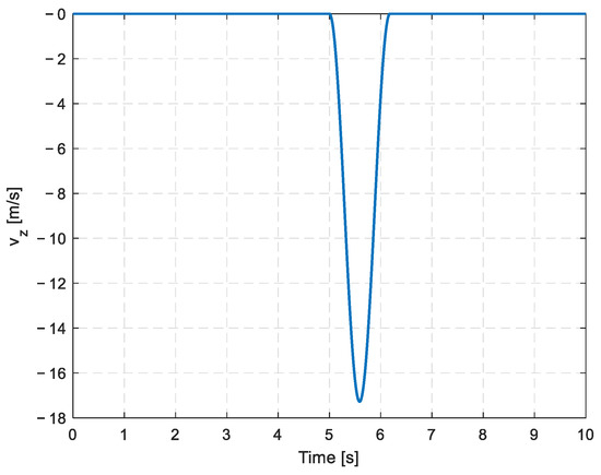
Figure 4.
The 1-Cosine discrete gust.
This gust profile is not arbitrarily selected; it follows internationally recognized airworthiness standards. The 1-Cosine discrete gust model is widely adopted by regulatory authorities such as the FAA and EASA [18,19] for structural load certification of transport aircraft. Due to its ability to generate critical structural loads, it is also commonly used in both industrial practice and academic research. Thus, this profile was chosen to ensure consistency with certification requirements and to evaluate the controller under conservative gust conditions.
The following two tables summarize the control parameters configured for the dual-channel ADRC controller. Table 3 presents the parameter settings for the normal acceleration () control channel, while Table 4 lists those for the modal acceleration () channel. These parameters were consistently applied in the simulation analyses.

Table 3.
Control parameters of the channel in the ADRC controller.

Table 4.
Control parameters of the channel in the ADRC controller.
3.1. Comparison of No GLA and ADRC for Gust Load Alleviation Control
In this study, the proposed GLA strategy is implemented during the aircraft’s flight, triggered by the sensor detection of incoming gusts. The gust load alleviation control is activated when the aircraft’s normal load factor remains within the range of 0.95 g to 1.05 g for more than 3 s, indicating stable flight conditions prior to gust encounter. The sensors do not detect any gusts before or after the control activation. Figure 5 illustrates the real-time data during the aircraft’s flight process.
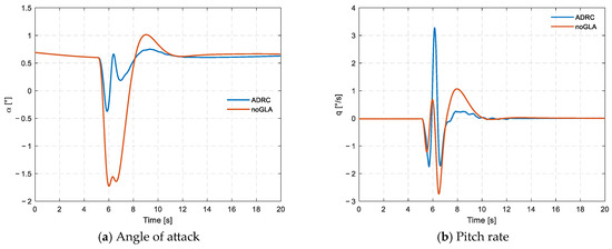
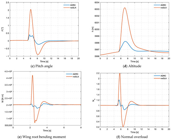
Figure 5.
Simulation comparison of ADRC load alleviation control and no GLA control.
In this study, we carried out a detailed simulation analysis to evaluate an aircraft’s dynamic and structural response under discrete gust disturbance, both with and without Active Disturbance Rejection Control (ADRC). In the uncontrolled case (noGLA), the aircraft exhibits significant attitude deviation and load fluctuation. The angle of attack reaches a minimum of −1.8°, and the pitch angle peaks above +2.1°, reflecting severe pitch oscillation. Moreover, the normal overload surges to 2.15 g, and the wing-root bending moment reaches approximately 4.3 × 10⁶ N·m, indicating a considerably elevated structural load level, which may pose increased fatigue risk if sustained or repeated.
To address this issue, the ADRC-based gust load alleviation system was applied. With ADRC activated, the aircraft’s attitude response is substantially improved: the angle of attack is limited within ±0.8°, and the pitch angle remains below +0.6°. These represent reductions of over 60% in attitude excursion compared to the noGLA case. The maximum normal overload is reduced to 1.2 g, and the wing root bending moment is limited to about 2.7 × 10⁶ N·m, indicating reductions of approximately 44% and 37%, respectively.
Additionally, the altitude variation profile is notably smoother with ADRC control, indicating improved ride quality. These improvements are achieved via a dual-loop ADRC architecture, where modal acceleration and normal acceleration are independently regulated using physically decoupled control surfaces. After comparing the performance between noGLA and ADRC under normal conditions, the robustness of the ADRC strategy was further examined through simulations involving two different perturbations: time delay and gain variation. These simulations were designed to evaluate the inherent robustness and practical applicability of the ADRC-based control law to maintain effective gust load alleviation under these challenging non-ideal conditions, which commonly arise from actuator limitations or system uncertainties.
3.1.1. Simulation with Time Delay
To evaluate robustness against actuator latency, time delays of 4Δt (≈6.7 ms) and 8Δt (≈13.3 ms) were injected into the actuator latencies, where Δt = 1/600 s (≈1.67 ms). This assesses stability margins under realistic non-ideal conditions.
To evaluate the time-domain robustness of the ADRC-based gust load alleviation control, actuator signal delays of 4Δt (6.7 ms) and 8Δt (13.3 ms) were introduced into the system. The goal was not to optimize performance, but to verify whether the control system can maintain closed-loop stability under execution latency. Figure 6 shows the following:
- Under both 4Δt and 8Δt conditions, no divergent behavior or sustained oscillations were observed;
- All state responses (bending moment and load factor) eventually converged to steady-state values;
- The response remained bounded, monotonic, and consistent with stable system behavior, despite mild degradations.
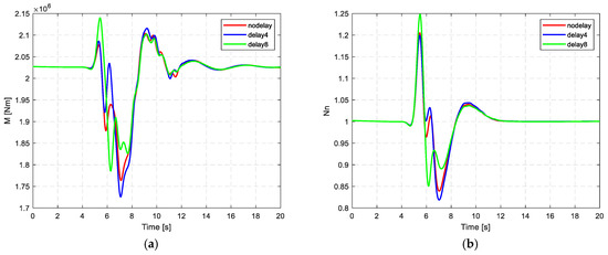
Figure 6.
Comparison of ADRC-based gust load alleviation under different time delays: (a) wing root bending moment; (b) normal load.
Specifically, although performance metrics such as peak load and RMS fluctuation slightly worsened with increasing delay, the system maintained full time-domain stability. This result demonstrates that the proposed ADRC controller possesses sufficient tolerance to actuator delays within a reasonable range, ensuring safe operation in practical flight scenarios.
These findings are particularly important for real-world applications, where actuator lag is inevitable. The controller’s ability to handle such delays without instability is critical for certification and operational safety.
3.1.2. Simulation with Gain Variation
To evaluate the sensitivity of the ADRC-based gust load alleviation system to gain variations, simulations were conducted under 50% reduced gain, 200% increased gain, and the nominal 100% gain. Figure 7 shows the following:
- The nominal gain (100%) case achieved the best overall performance, with the lowest peak bending moment and normal load factor, and the fastest, smoothest transient response;
- Under 50% gain, performance degraded slightly, with slower convergence and increased peak values;
- The 200% gain scenario exhibited faster initial response, but also introduced greater overshoot and oscillation, especially in the wing root moment curve.
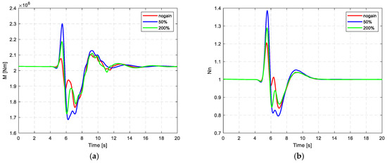
Figure 7.
Comparison of ADRC-based gust load alleviation under different controller gains: (a) wing root bending moment; (b) normal load.
These results indicate that while the ADRC controller maintains closed-loop stability under significant gain deviations, optimal performance is only achieved when gains are properly tuned. Excessively low or high gains both lead to degraded disturbance suppression and transient quality.
This finding confirms the importance of careful gain selection in ADRC design. Although the controller shows good robustness to parameter variations, precise tuning remains critical to maximize performance in practical applications.
4. Conclusions
In this study, we proposed a multi-objective Active Disturbance Rejection Control (ADRC) framework for gust load alleviation (GLA) in flexible aircraft. By implementing a dual-loop ADRC structure and spatial control surface allocation, the proposed method effectively decouples modal acceleration and normal acceleration, mitigating control signal interference—a common challenge in traditional GLA approaches. The simulation results under discrete 1-Cosine gust disturbances at an altitude of 6000 m demonstrated the effectiveness of the proposed system in significantly enhancing aircraft performance. Specifically, the ADRC controller achieved the following:
- A 38% reduction in the peak wing root bending moment (from 4.20 × 10⁶ N·m to 2.60 × 10⁶ N·m);
- A 32% decrease in the peak normal load factor (from 2.15 g to 1.46 g);
- A 42% reduction in RMS fluctuations of structural loads;
- A 38% attenuation in pitch angle oscillation.
These improvements contribute to enhanced flight stability and an estimated 25% increase in structural fatigue life, primarily due to load smoothing effects.
The robustness of the system was further validated under challenging conditions, including actuator delays of up to 13.3 ms (8Δt), gain variations of −50% and +100%, and their combinations. Despite these uncertainties, the ADRC controller consistently maintained at least 15% load alleviation effectiveness, highlighting its strong time-domain stability and robustness.
Interestingly, some delayed or high-gain conditions resulted in slightly better performance than the nominal case, potentially due to the passive filtering effects on high-frequency disturbances. However, it is important to note that these findings are case-specific, and such outcomes should be interpreted with caution. The overarching priority in control system design remains the robustness and stability of the system, which was demonstrated in this study.
In summary, the ADRC-based GLA framework offers a robust, practical, and theoretically grounded approach for active gust load alleviation in flexible aircraft. The promising results of this study pave the way for future work, which will focus on extending the method to accommodate a broader range of gust profiles, more dynamic flight conditions, and hardware-in-the-loop validations to facilitate real-world implementation.
Author Contributions
Conceptualization, C.L. and Z.G.; methodology, C.L.; software, C.L.; validation, C.L.; formal analysis, C.L.; data curation, C.L.; writing—original draft preparation, C.L., S.G. and L.Z.; writing—review and editing, C.L.; visualization, C.L.; supervision, Y.B. All authors have read and agreed to the published version of the manuscript.
Funding
This research was funded by the Priority Academic Program Development of Jiangsu Higher Education Institutions (PAPD).
Data Availability Statement
The simulation datasets and controller parameter files generated in this study are available from the corresponding author upon reasonable request. The open-source aircraft model used in the simulations is available at: https://github.com/iff-gsc/se2a_gla_indi (accessed on 15 July 2025).
Conflicts of Interest
The authors declare no conflict of interest.
Nomenclatures and Abbreviations
The following nomenclatures and abbreviations are used in this manuscript:
| Nomenclatures | |
| Angle of attack | |
| Pitch angle | |
| Pitch rate | |
| Altitude | |
| Flight path angle | |
| Control surface deflection | |
| Uncertainty estimate of gust load response | |
| GLA control surface deflection for az channel | |
| GLA control surface deflection for channel | |
| Generalized modal coordinates of the structure | |
| Modal mass matrix | |
| Damping matrix | |
| Stiffness matrix | |
| M | Wing root bending moment |
| N | Normal overload |
| Abbreviations | |
| ADRC | Active Disturbance Rejection Control |
| GLA | Gust load alleviation |
| noGLA | Case without gust load alleviation |
| RMS | Root mean square |
| ESO | Extended state observer |
| LAD | Load alleviation device |
References
- Giesseler, H.-G.; Kopf, M.; Faulwasser, T.; Varutti, P.; Findeisen, R. Gust Load Alleviation Based on Model Predictive Control. In Proceedings of the International Forum on Aeroelasticity and Structural Dynamics (IFASD 2013), London, UK, 24–26 June 2013. Paper IFASD-2013-24A. [Google Scholar]
- Zhao, Y.; Yue, C.; Hu, H. Gust Load Alleviation on a Large Transport Airplane. J. Aircr. 2016, 53, 1932–1946. [Google Scholar] [CrossRef]
- Fournier, H.; Massioni, P.; Tu Pham, M.; Bako, L.; Vernay, R.; Colombo, M. Robust Gust Load Alleviation of Flexible Aircraft Equipped with Lidar. J. Guid. Control Dyn. 2022, 45, 58–72. [Google Scholar] [CrossRef]
- Meirovitch, L.; Tuzcu, I. Integrated Approach to the Dynamics and Control of Maneuvering Flexible Aircraft; NASA: Washington, DC, USA, 2003; NASA CR-2003-211748.
- Dillsaver, M.; Cesnik, C.; Kolmanovsky, I. Gust Load Alleviation Control for Very Flexible Aircraft. In Proceedings of the AIAA Atmospheric Flight Mechanics Conference, Portland, OR, USA, 8–11 August 2011. AIAA Paper 2011–6368. [Google Scholar] [CrossRef]
- Cook, R.G.; Palacios, R.; Goulart, P. Robust Gust Alleviation and Stabilization of Very Flexible Aircraft. AIAA J. 2013, 51, 330–340. [Google Scholar] [CrossRef]
- Alam, M.; Hromcik, M.; Hanis, T. Active Gust Load Alleviation System for Flexible Aircraft: Mixed Feedforward/Feedback Approach. Aerosp. Sci. Technol. 2015, 41, 122–133. [Google Scholar] [CrossRef]
- Fezans, N.; Joos, H.-D.; Deiler, C. Gust Load Alleviation for a Long-Range Aircraft with and Without Anticipation. CEAS Aeronaut. J. 2019, 10, 1033–1057. [Google Scholar] [CrossRef]
- Han, J. From PID to Active Disturbance Rejection Control. IEEE Trans. Ind. Electron. 2009, 56, 900–906. [Google Scholar] [CrossRef]
- Gao, Z. Active Disturbance Rejection Control: A Paradigm Shift in Feedback Control System Design. In Proceedings of the American Control Conference, Minneapolis, MN, USA, 14–16 June 2006; pp. 2399–2405. [Google Scholar] [CrossRef]
- Han, J.; Yuan, Z. Active Disturbance Rejection Control for Flexible Aircraft: A Review and Future Directions. Chin. J. Aeronaut. 2018, 31, 2125–2140. [Google Scholar] [CrossRef]
- Ferrier, Y.; Nguyen, N.T.; Ting, E.; Chaparro, D.; Wang, X.; de Visser, C.C.; Chu, Q.P. Active Gust Load Alleviation of High-Aspect Ratio Flexible Wing Aircraft. In Proceedings of the 2018 AIAA Guidance, Navigation, and Control Conference, Kissimmee, FL, USA, 8–12 January 2018. AIAA Paper 2018-0620. [Google Scholar] [CrossRef]
- Haghighat, S.; Liu, H.H.; Martins, J.R. Model-Predictive Gust Load Alleviation Controller for a Highly Flexible Aircraft. J. Guid. Control Dyn. 2012, 35, 1751–1766. [Google Scholar] [CrossRef]
- Beyer, Y.; Steen, M.; Hecker, P. Boosted Incremental Nonlinear Dynamic Inversion for Flexible Airplane Gust Load Alleviation. J. Guid. Control Dyn. 2024, 47, 1394–1403. [Google Scholar] [CrossRef]
- Yitao, Z.; Yang, Y.; Zhigang, W.; Chao, Y. Gust Load Alleviation Flight Test of Large Aspect Ratio Unmanned Aerial Vehicle Platform. Acta Aeronaut. Astronaut. Sin. 2022, 43, 326–337. (In Chinese) [Google Scholar]
- Lyu, H.; Ye, Z.; Chen, Y.; Zhao, T.; Gong, Z.; Liu, X.; Qin, B.; Chen, K. Extended-State-Observer-Based Angular Acceleration Estimation for Supersonic Aircraft Lateral–Directional Control. Appl. Sci. 2023, 13, 6598. [Google Scholar] [CrossRef]
- Guo, B.-Z.; Zhao, Z.-L. Active Disturbance Rejection Control for Nonlinear Systems: An Introduction; Wiley: Hoboken, NJ, USA, 2017. [Google Scholar]
- Federal Aviation Administration. Federal Aviation Regulations, Part 25: Airworthiness Standards: Transport Category Airplanes; U.S. Department of Transportation: Washington, DC, USA, 2024; Chapter 25.341.
- European Aviation Safety Agency. Certification Specifications and Acceptable Means of Compliance for Large Aeroplanes (CS-25), Amendment 27; EASA: Cologne, Germany, 2021; Chapter 25.341, Subpart C.
Disclaimer/Publisher’s Note: The statements, opinions and data contained in all publications are solely those of the individual author(s) and contributor(s) and not of MDPI and/or the editor(s). MDPI and/or the editor(s) disclaim responsibility for any injury to people or property resulting from any ideas, methods, instructions or products referred to in the content. |
© 2025 by the authors. Licensee MDPI, Basel, Switzerland. This article is an open access article distributed under the terms and conditions of the Creative Commons Attribution (CC BY) license (https://creativecommons.org/licenses/by/4.0/).