Abstract
The purpose of this paper is to present a vibration dissipation device that sends vibration signals from the manipulated tool in the workplace to the operator’s hand by improving its ergonomic appearance and materials. Compared with another vibration dissipation device, this one was previously designed and patented. This paper is based on two studies: one theoretical and the other experimental (the latter regarding the material used). The first part is represented by the design and simulation of the device and a static analysis by FEA in SolidWorks 2022. The stresses to which the materials of the device’s bracelets are subjected are studied in this article; then, the resistance of the device’s materials to the tensile and deformation stresses they are subjected to is presented. All these studies complement DIAV equipment’s functionality in terms of its components’ design and assembly. Emphasis is placed on its shape and ease of assembly and the operator’s dexterity in mechanical processes so that DIAV does not limit them. In addition, from the point of view of its design, emphasis is placed on its fixation so that it is easy to assemble and is within reach of any operator. The appropriate choice of materials for the components of the DIAV device is of major importance both in terms of strength, ergonomics, and weight. The experimental results validate the theoretical results obtained through the FEA simulation in SolidWorks, and this fact confirms the usefulness and functionality of the DIAV device from the perspective of vibration attenuation.
1. Introduction
The objective of this paper is to present both theoretical and experimental aspects of the materials used in a vibration dissipation device that transmits vibrations from the manipulated tool in the workplace to the operator’s hand. The advantages of the DIAV device regarding the improvement of ergonomics and the component materials are detailed and compared with another previously designed and patented device whose materials, method of use, assembly, and ergonomics leave much to be desired [1]. The disadvantages of DIAV could be the rapid wear of the silicone semi-bracelet on the palm. This paper will refer to two vibration dissipators: one functional and patented but without an ergonomic shape, hereinafter called DIBRE (innovation vibrating dissipation device/equipment), and the new one presented in this paper, called DIAV, which improves the ergonomics of the first model, the method of assembly, and the quality of the materials used.
The existence of the DIBRE device and the problems that arose with its use regarding its materials and rough assembly (the device upon which measurements were also performed) led to this study. Therefore, this new DIAV device will bring improvements to the shape, assembly, and materials of the device.
It should be mentioned that the dissipation equipment, regardless of which of the two previously described models is being discussed, has the following basic and auxiliary components:
- (a)
- The basic component is a commercial mini attenuator that has all the desired mechanical characteristics (rigidity and damping). It was chosen according to the calculations that are explained in this paper. Its role is to dissipate the vibrations transmitted from the hand-held tool to the hand so that they do not propagate further to the forearm and elbow; we mention that the complete elimination of these transmitted vibrations cannot be achieved.
- (b)
- The auxiliary components include bracelets, connecting rods, etc., without which this mini attenuator could not fulfill its role, because it is a component of them. All these work together as an assembly called vibration dissipation equipment.
The methods addressed in this paper present the theory and measurements of the DIBRE device. They highlight the justification for designing and wearing such a device, as well as the advantages of improving its shape and materials through the new DIAV device. The comparison of the theoretical and experimental results of DIBRE, as well as the comparison of the two devices from a theoretical point of view, justifies the performance of this study.
To explain this study concerning the materials of the vibration protection and dissipation device, several ergonomic elements will be highlighted. According to Directive 2002/44/EC of the European Parliament and of the Council of 25 June 2002 on the minimum health and safety requirements regarding the exposure of workers to the risks arising from physical agents (vibration) [2], any operator working in a vibration-induced environment and using vibrating tools or devices is required to wear protective equipment. In the case of the hand–arm system, regarding the hand, the only protective equipment for the hand is a glove [3]. The gloves are made of different materials, and their role is to reduce the transmission of vibrations from the tool to the hand; however, they also reduce the operator’s dexterity and, often, are not worn throughout the work process.
In this sense, this paper develops an innovative idea, namely the design of a device to minimize the vibrations transmitted to the operator’s hand at the workplace. It is essential in terms of ergonomics [4], its role, and functionality [5]. In short, this device, called DIAV, will be presented in the following sections.
Ergonomics relates to several aspects that are considered in the design of this DIAV device. It considers the working conditions of the personnel by adapting to the specific workplace to ensure efficiency, safety, and comfort [5,6]. The specialized literature [7,8] expresses itself in various ways regarding ergonomics, but essentially, it includes the three aspects previously mentioned: functionality, safety, and comfort.
The specialized literature [9] mentions that each person has different physiological and behavioral responses. These depend on the factors that workers are exposed to during the work process, such as exposure to vibrations, cognitive and movement capacities, positions, the repeatability of processes, and environmental factors such as temperature, etc. [10]. Thus, workplace vibrations can cause an imbalance in a worker’s health that interferes with work activity and also causes the appearance of unpleasant symptoms such as dizziness, tingling and a loss of finger dexterity [11], and physical discomfort such as mild back pain [9].
Regarding the last paragraph, it can be stated that people who handle industrial devices and equipment, which inevitably produce vibrations through their mode of operation (for example, the pick-up machine, the drill, etc.), must be protected from them [12]. Workers who operate these machines are vulnerable and are at risk of developing occupational diseases, the most common being white finger syndrome [13]. These effects disrupt the professional performance of people exposed to vibrations through the appearance of occupational diseases such as muscular, bone, or vascular diseases of the upper limbs [14]. For this reason, workers are instructed to wear protective equipment at work. Devices such as DIAV, unlike gloves, leave the fingers free, improving the worker’s dexterity. This device not only reduces the likelihood of getting sick at work but can also make the work process more comfortable by making it easier for them to handle the tool in operation [15,16].
Finally, all these aspects increase the efficiency of the production process, which is desired by companies of all types [7,8]. In other words, it can be said that ergonomics is the equivalent of production efficiency. Any protective equipment must be ergonomic in shape, convenient, and easy to handle. This equipment must not hinder the activities of the operator, from the point of view of functionality. DIAV must fulfill its role as an attenuator of the vibrations transmitted to the hand–arm system. This paper aims to validate the theoretical results of DIAV obtained via FEA simulation and experimental material testing, but also consider its mass and dimensions, optimizing it to the smallest possible dimensions.
2. Device Role Description
2.1. Mathematical Modeling of the Hand-Arm System with the Dissipation Device
A mathematical model of the hand–arm system that includes a vibration attenuator device is presented briefly in Figure 1. This is mounted parallel to the arm. This model has been presented in other studies [16] using a model and equations, but for more correct validation in this paper, namely a comparison of the two equipment models, the paper uses it. Thus, the simulation of its movement is shown in Figure 2a–c.
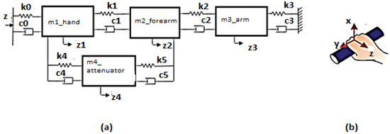
Figure 1.
(a) Linear mechanical system of the hand–arm assembly with four degrees of freedom and with the vibration dissipator mounted on the forearm (between the wrist and the elbow) [16]; (b) Anatomical coordinate system.
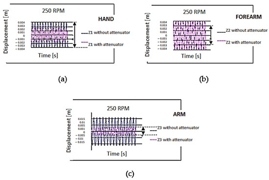
Figure 2.
Transmission of the vibrations along the hand–arm system, using a mini attenuator (250 RPM). (a) Displacement of the hand—z1 [m]; (b) Displacement of the forearm—z2 [m]; (c) Displacement of the arm—z3 [m].
The hand–arm model is a mechanical system considered to have concentrated masses for the hand (m1), forearm (m2) and arm (m3), and (m4) is the mass of the mini-vibration attenuator mounted between the hand and forearm. The mechanical characteristics of elasticity and damping are taken from the literature [15,16], and the masses are determined experimentally, according to the anatomical data, and shown in Table 1.

Table 1.
Mechanical properties of the hand–arm system [15].
To solve the system of equations associated with the hand–arm system, it was hypothesized that the mechanical model is linear [16] and has four degrees of freedom, and the joints at the wrist, elbow, and shoulder were not taken into account. It is considered that the system is subjected to te vibrations of a tool that has a velocity of 250 RPM (revolutions per minute).
The solutions of the system of Equation (1), corresponding to the model given in Figure 1, are obtained after integration with the 4th-order Runge–Kutta method and give the solutions, respectively, of the displacements of the four masses along the Oz axis of the anatomical system (along the hand to the shoulder):
By solving the system of Equation (1), the graphical solutions given in Figure 2a–c result; in these, the displacements of the masses of the hand–arm system using or not using a vibration dissipator are highlighted.
In Figure 2b,c, it can be observed that the minimization of the transmission of the vibrations for the hand is insignificant. Still, to the forearm and arm, this is much minimized when an equipment vibration attenuator is mounted along the forearm. The displacements (z2) for the forearm are minimized from 0.003 m to 0.002 m (Figure 2b), and to the arm, these are minimized from 0.01 to 0.003 m (Figure 2c) for the same revolution of 250 RPM.
2.2. Description of the DIBRE Dissipating Device
Based on [17] and retaining the idea that a dynamic absorber reduces vibrations, the existing DIBRE vibration dissipator, mounted on the forearm, was taken into account. The designed DIAV will be improved ergonomically, as a mounting method and in terms of component materials, but not in terms of functionality, since the use of the mini attenuator in the equipment made it functional. An initial starting point was the dimensions of this device, so that this would not interfere with its functionality.
Equation (2) and Figure 3 are in accordance with the ACE catalog, 2010 [18].

Figure 3.
Functional diagram for choosing the FA 1008 VB vibration attenuator (ACE Controls International Inc., Haydock, Great Britain, UK) [18].
Wi—kinetic energy (i = 1–4) [J];
v, vd—total piston velocity, and piston velocity [mm/s];
M—moment [Nm];
s—piston stroke [mm];
R—dynamic element radius [mm];
C—constant;
ω—angular velocity [rad/s];
me—equivalent mass [kg].
Thus, the DIBRE [19] vibration dissipator (Figure 4) includes a commercially available FA 1008VB mini-vibration attenuator (according to Table 2), which consists of the following components:
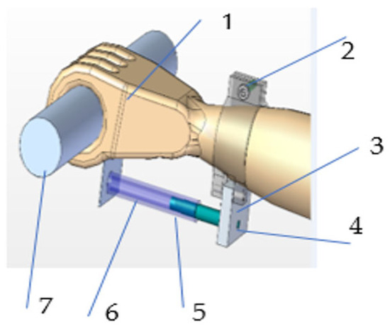
Figure 4.
DIBRE vibration dissipator [19]: (1) rubber sleeve; (2) screw; (3) metal plate; (4) pins; (5) ACE shock attenuator; (6) extension; (7) handle.
Table 2.
Technical characteristics of the vibration mini attenuator FA 1008 VB catalog [18].
- Component (1) is a rubber sleeve (mounted on the hand),
- Component (2) is a screw (the one on the sleeve),
- Component (3) is a metal plate—E295 (which is connected to the sleeve),
- Component (4) is pins E295 pins (2 pcs., they connect the plate to the sleeve),
- Component (5) is an ACE shock attenuator,
- Component (6) is an extension E295 (graphically symbolized by a transparent tube made of transparent plastic),
- Component (7) is a handle E295 (the tool is tightened by hand).
The mini-attenuator included in DIBRE and presented in Figure 5 dissipates vibrations transmitted to the hand by devices. This study also aims to test the material of the metal bracelets that include the mini attenuator in Figure 5.
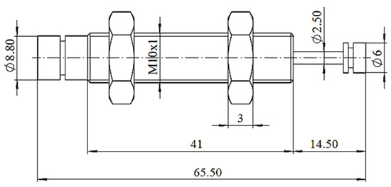
Figure 5.
Dimensions of FA 1008 VB [18].
A static analysis of the mini attenuator–bracelet joint in terms of the stresses to which they are subjected, as well as the displacements, was considered useful through the analysis of the FEA simulation.
2.3. Experimental Research on the Device DIBRE
Preliminary experimental research on the transmission of mechanical vibrations to the hand–arm system using a designed vibration dissipation system, as shown in Figure 4 and Figure 6, was carried out by measuring mechanical vibrations using a drilling machine and using a vibration dissipation device that included a mini-vibration attenuator mounted on the forearm. The machine drills a piece of chemically treated MDF using a 10 cm drill bit. The experiment measures the vibrations transmitted by the tool when it operates with and without percussion (Figure 7) for one hour, with 10 min of drilling and 2 min of rest between them. The operator was a 35-year-old man weighing 80 kg. The measurements were performed with a digital vibrometer (SVAN 958, Svantek company, Warszawa, Poland), which used a triaxial accelerometer, but the vibrations were measured only along the Oz axis. The accelerometer was magnetically mounted on the metal bracelet of the wrist/forearm.
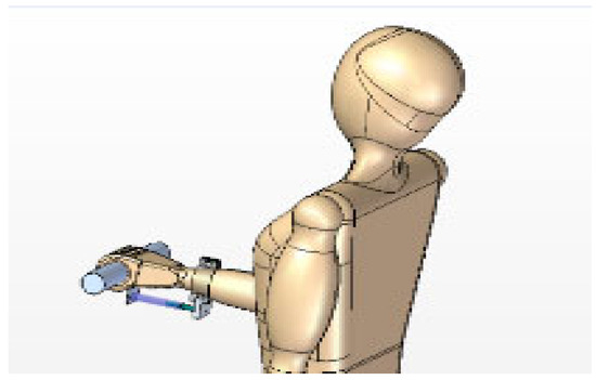
Figure 6.
DIBRE vibration dissipator device, incorporating a vibration mini-attenuator [19].
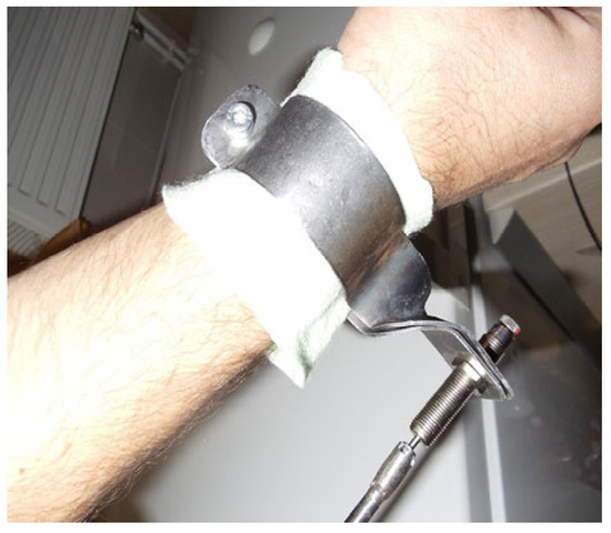
Figure 7.
Vibration dissipator—padding the bracelet with felt.
Since the metal half-bracelets were not padded, for the operator’s comfort and to fix them during work operations (to avoid their rotation or slipping), they were successively padded with felt and sponge, and measurements were taken in both situations.
For the validation of the mini attenuator, the dissipation equipment (Figure 7) was practically made according to the patented device [19], which had a simple shape (without taking into account ergonomics) and was mounted on the forearm between the wrist and the hand. This device had a metal wrist/forearm bracelet, made of 1.5 mm thick sheet metal, except for the bracelet on the inside of the hand (palm), which was made of a soft material (leather) and fixed with rivets. The bracelets were mounted together by means of an extension (6) that supported the mini attenuator, which is made of plastic. All this aimed to reduce the vibrations transmitted from the hand along the arm to the shoulder of the person using the drill (Figure 7). The metal bracelet was padded with felt for comfort, and in both cases vibration measurements were performed. The inner lining of the metal bracelets has been designed to prevent skin damage and to prevent the device from slipping on the forearm during use, which could block the movements of the operator’s forearm.
The damping device was mounted between the wrist and the elbow, parallel to the forearm, in accordance with the theoretical model studied, both in terms of placement and the technical characteristics (stiffening and damping). Also, the weight of the dissipator device is 0.5 kg, identical to the theoretical model.
The results obtained from the measurements were analyzed as their average and recorded directly on the device, then downloaded to the computer.
The first analysis of the results presented in Figure 8a,b shows that vibrations are transmitted along the hand–arm system to a lesser extent if a vibration-dissipating device [16] is mounted along the forearm. Displacements range from 0.07 to 0.03 m for the hand and from 0.08 to 0.03 m for the forearm, noting that the differences in the measurements are unimportant if the padding of the metal bracelet is made of felt.
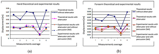
Figure 8.
Vibrations transmitted to the forearm (theoretical and experimental) with padding made of (a) felt and (b) using a drill with/without percussion.
2.4. DIAV Device, an Improved Version of the DIBRE Device
This study starts with a vibration-dissipating device for the hand–arm system, which exists and has been theoretically patented [19]. The functionality of the device is achieved through a reduction in the vibrations transmitted from mechanical tools to the operator’s hand, but in which the ergonomics of the shape, its fixation on the hand, and its materials can be improved. Starting from the existing device, the DIAV device was designed to have the basic constructive characteristics of the current one, but its shape, mass, and materials, in other words, its ergonomics, have been improved.
The DIAV equipment (Figure 9) consists of three basic components: two bracelets, one for the palm (1) and one for the wrist (2), connected by a vibration attenuator (3). The DIAV equipment was intended to not exceed 500 g.
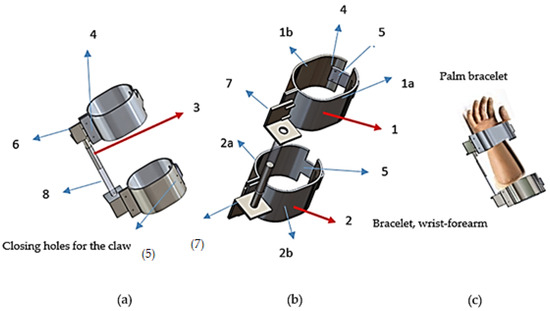
Figure 9.
DIAV vibration damping device; (a) font view of dissipator, (b) elements of dissipator, (c) mode of montages of dissipator.
The dimensions (diameter) of the bracelets (Figure 9) are universal, and as a novelty, they can now be adjusted by up to 1 cm from their attachment points with the claw (5). The design of the DIAV equipment was based on shape, materials, and functionality.
The design studied contains components (4–8) that connect the basic components (1–2–3) and ensure the functionality of the DIAV device. The following describes the functionality and assembly of each component of the device.
The DIAV device (Figure 9) was designed to be worn on the hand and upper wrist (maybe the forearm). For this purpose, two bracelets, designated 1 and 2, were designed, one for the hand and one for the upper wrist. Each bracelet consists of two half-bracelets that are articulated together by a hinge at the wrist (2a, 2b) and by riveting at the palm (1a, 1b), depending on the material composition of each half-bracelet. The reason for choosing these materials will be made explicit in the Materials sub-section, and this stage will simply refer to the materials as metallic and non-metallic (silicone). Regarding the functionality of the device in terms of shape and maneuverability, it can be said that the bracelet (1) has two semi-bracelets. One is a metal semi-bracelet (1a), and the other semi-bracelet is made of silicone tape (1b). Both semi-bracelets are fastened together with rivets with a semi-round head (4), and the non-metallic (silicone) one has a plastic clip (5) fixed on the metal semi-bracelet in the same way with rivets (4), only with smaller dimensions. A non-metallic silicone semi-bracelet was chosen for its flexibility, softness, and excellent chemical resistance (like in the case of using certain paints, for example, a paint gun), but also because this is the part that is placed in the palm and does not disturb or embarrass the operator during the work process. The ABS plastic clip (5), which is used to attach the silicone semi-bracelet, was chosen for its strength and durability. It can be attached to two holes, so it can slide up to 1 cm in terms of tightening and fixing it to the hand.
The bracelet (2) consists of metal semi-bracelets (2a and 2b) that are connected by a hinge (6) to ensure easy mounting/dismounting on the forearm/wrist. The vibration mini-attenuator connects the bracelets. An L-shaped connecting element (7) is connected to both bracelets, which is the support on which the movable mini attenuator head (3) will be fixed, and a transparent plastic support (8) will move the mobile part of the attenuator during vibratory movements (3). This is the commercially available FA 1008 VB mini attenuator from the manufacturing company ACE [18]. This corresponds to the required damping characteristics, having a stroke of up to 15 mm and a force distribution of up to 1500 N/m; to visualize this stroke, the support in which this piston moves is made of a non-metallic material (transparent plastic (8)). From an ergonomic point of view, the metal semi-bracelets (2) on the upper part of the wrist/forearm are lined with silicone strips to not irritate the skin.
In other words, the most improved feature of the DIAV device compared to the previous one is the way it is fixed on the hand by attaching the semi-bracelet with a claw; the previous one was fixed with screws and nuts, and it could not be assembled by one person. In addition, the new DIAV device enables one to adjust the bracelets on the hand through the two holes and the claw, and is lined on the metal part of the bracelets with non-metallic material (silicone).
3. Theoretical Modeling with FEA
To verify whether the components designed, both in terms of the shape and material of the DIAV device, withstand mechanical stresses (displacements) and even strength stresses (shear/tension or elongation), two static simulations called Static 1 and Static 2 were performed, both with a force distribution of up to 1500 N/m2 (value estimated of specialized literature [20]). In the case of Static 1, this distribution of force was applied on the metallic semi-bracelets 1a, 1b, 2b (Figure 10a,b). In the second study, the force distribution was applied to the semi-bracelets, but also the connecting part between the two, e.g., element (8). From experience of the real, patented, and practically realized device [19], these two locations are the most stressed by vibrations.
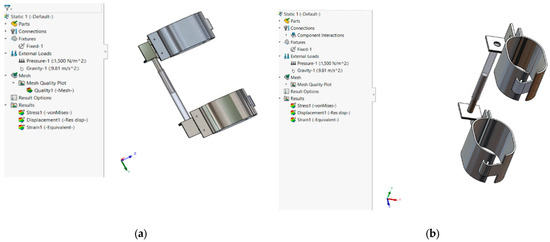
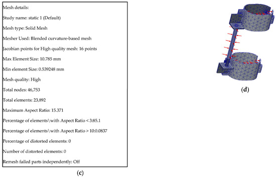
Figure 10.
Choice of materials for the DIAV device: (a) Palm bracelet; (b) Wrist bracelet in Static 1 simulation; (c) Mesh details; (d) Mesh structure.
Because the equipment was not subjected to dynamic loads and simplifying assumptions were considered in the mathematical model, in the current research, static FEA simulation, from the point of view of the equipment parameters, forces, and material parameters, was considered sufficient.
The resistance of the S235JR material of the bracelets, Mairon, Galați, Romania [21] to tension/compression and torsion will be checked.
In the case of FEA simulation, it is interested in the behavior of the material under stress, but especially in its displacements. Regarding the selection of the material for the metal bracelet, it has a less formal selection, aiming to satisfy the technical economic conditions. In the case of DIBRE, E295 [20] non-alloy steel was used, and in the case of DIAV, S235JR non-alloy steel was used. The selection of metal bracelet materials in this paper aims to meet the mechanical properties of the device while keeping the cost low. In terms of human comfort, the metal bracelets are lined with polyurethane material wrapped in waterproof textile fabric. These materials do not significantly influence the mechanical properties of the metal bracelets, which is why they have not been analyzed in terms of numerical simulation.
Table 3 shows the chemical composition of E295 steel [20] and the mechanical properties of materials E295 and S235JR according to the European standard SR EN 10025-2:2004 for hot-rolled structural steel. Part 2—Technical delivery conditions for non-alloy structural steels [21].
Table 3.
The chemical composition of E295 steels (wt.%).
Table 4 presents the mechanical properties of E295 [20] and S235JR steels Mairon, Galați, Romania [21].
Table 4.
Mechanical properties of E295 and S235JR steels.
The simulation was performed with SolidWorks 2022, using the Jacobian algorithm, the number of nodes chosen was around 50,000, and the triangular mesh was considered the most relevant in the study (Figure 10c).
3.1. Static 1 Simulation of the DIAV Equipment with Force Applied on the Metal Semi-Bracelet
The following presents the first case with the distribution force applied to the semi-bracelets 1a, b, and 2a, b (Figure 10). Figure 10a,b show the mounting position of the DIAV equipment on the hand, where the upper bracelet is intended for the palm and the lower one is intended for the wrist/forearm. Figure 10c,d show the mesh details and structure. Regarding the data for creating the mesh structure, these are shown in Figure 10c with a mesh analysis according to the Jacobian principle, in 16 points, and with a total number of 46,753 nodes and 23,872 mesh elements. This determines the choice of material for the metallic semi-bracelets of steel S235JR.
Following the FEA simulation (Figure 11), after fixing the surfaces (superior bracelet), defining the forces and generating the mesh surfaces, three cases for DIAV emerge for the stress requests σ (Figure 11a) and displacement (Figure 11b). Regarding the data for creating the mesh structure, these are shown in Figure 11c with a mesh analysis according to the Jacobian principle in 16 points and with a total number of 46,753 nodes and 23,872 mesh elements.
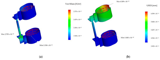
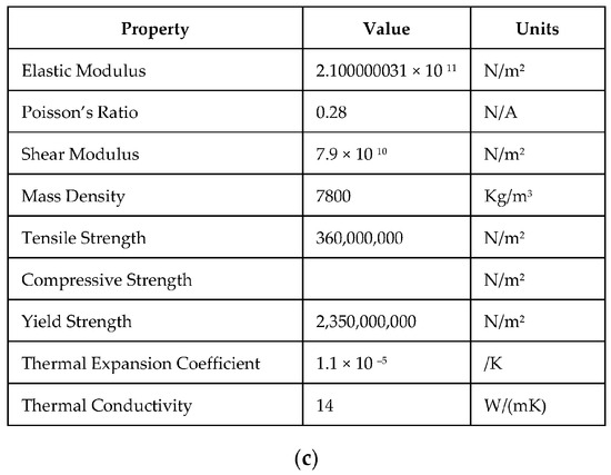
Figure 11.
Simulations of DIAV Static 1 analysis with tensile loads: (a) Von Mises tension, (b) Displacement, (c) Material properties (S235JR).
Two aspects are observed regarding the DIAV simulation: one related to the displacements highlighted by the FEA representation (Figure 12b) and another related to the resistance of the materials from which the device bracelets are made, represented by the appearance of stress and strain (Figure 12a). It is observed that in the DIAV resistance simulations, there are no areas that involve reduced resistance (marked in red or orange). On the other hand, in those that involve the transmission of vibrations (displacements), as shown in Figure 12b, larger displacements can be observed, marked on the bracelet in red and orange. Therefore, DIAV is more exposed to displacements in critical cases, especially the metallic palm semi-bracelet, which is up to a maximum of 0.65 mm and represented by the red and orange areas, which show how exposed the bracelet of the palm is to vibrations. The attenuator (3) is functional because the bracelet on the wrist/forearm is in the blue comfort zone, in terms of tensions and deformations. The area is not exposed to vibrations, which was desired, but the mini-attenuators require the connecting element (8), in conformity with Figure 9a,b.
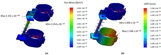
Figure 12.
Simulations of DIAV Static 1 analysis in torsion: (a) Von Mises tension, (b) Displacement.
From the point of view of the resistance of the S235JR metal material chosen for the bracelets, it is observed that during mechanical stress, such as during the tensile stress test, only the shock absorber rod is more stressed within the resistance limits of 27.5 MPa, and the attenuator and the connecting element have a more stressed area in the clamping area.
During the torsion test, it was observed that the values obtained from the simulation reached a maximum of 214.1 MPa in the clamping area and the hinges, as shown in Figure 12a. The largest displacements, during torsion, are in the clamping area of the bracelet and have values of 1.748 mm, as shown in Figure 12b.
3.2. Static 2 Simulation with Force Applied on the Metal Bracelets and the Mini Attenuator Rod
Regarding the second study Static 2, in which the static FEA simulation of the DIAV device was performed when the force distribution was up to 1500 N, it acts in the form of pressure on both the S235JR metal semi-bracelets and the connecting mini attenuator rod (Figure 13). The same cases are analyzed for stress, deformation, displacement and torsion.
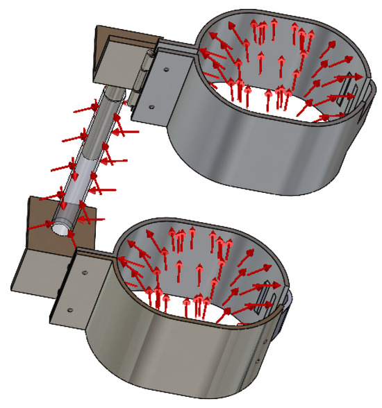
Figure 13.
Simulation and material selection in Static 2 simulation for the DIAV device: Palm bracelet; Wrist/forehand bracelet.
The DIAV results of the static simulation for stress, displacement, and strain under these conditions are shown in Figure 14a–c. The data for creating the mesh structure are shown in Figure 14c with the same mesh analysis according to the Jacobian principle, in 16 points and with a total number of 46,753 nodes, as in the Static 1 simulation.
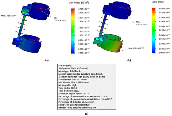
Figure 14.
FEA simulation of Static 2 analysis: (a) Von Mises stress, (b) Displacements, (c) Mesh details.
This is analogous to the previous study Static 1 (Figure 11), (it is mentioned that material properties are the same in Figure 11c) and Figure 14a. A force distribution of 1500 N acting on the metal semi-bracelet and the shock absorber support is predicted. It is observed that in this case, in all types of FEA simulations (Figure 14a–c), the DIAV device reacts much less to the action of vibrations in terms of Von Mises stresses of 27.55 MPa (Figure 14a). Regarding the displacements, as shown in Figure 14b, these are maximum at 0.65 mm. The red and orange areas show how exposed the palm metallic bracelet is to vibrations, which suggests that the mini attenuator is functional in its role of minimizing their transmission to the wrist bracelet. Being in the blue comfort zone means it has not been exposed to high vibrations, which is desirable.
Regarding the conditions of force application in this case, although different, the S235JR metal material of the wrist bracelets behaves well under stress and strain, and it is observed that only the damper rod is more stressed (Figure 14a). Regarding strain, it is seen that there is a small risk zone for the mini attenuator near the area where the mini attenuator is fixed to the element. Regarding the maximum values given by the von Mises stresses, these are like the first study, at 27.55 MPa (Figure 14a), and displacements values of 0.65 mm were obtained (Figure 14b).
Following the design and selection of materials described above, from the SolidWorks library, the DIAV assembly falls within the desired mass of 500 g and fulfills its functional role of reducing vibrations from the hand to the wrist (Figure 11b and Figure 14b). This can be observed in the two cases of force loads when, from the bracelet on the palm to the wrist/forearm, the displacements pass from risk areas (red) to normal operating areas (blue). This proves that the mini-attenuator produced by ACE takes over most of the vibrations transmitted by the equipment, which no longer propagates to the forearm and upper arm.
The values obtained during the torsion stress test via simulations were a maximum of 207.2 MPa in the clamping area and the hinges, as shown in Figure 15a. The largest displacements during torsion are in the clamping area of the bracelet and have values of 1.748 mm, as shown in Figure 15b.
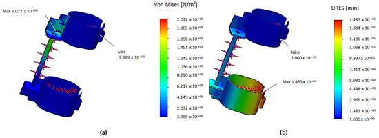
Figure 15.
Simulations of DIAV in Static 2 analysis for torsion: (a) Von Mises tension, (b) Displacement.
Regarding the mechanical stresses to which the equipment is subjected, the metallic components of the DIAV device do not reach dangerous values of fatigue, deformation, or breakage phenomena. The only component at risk, due to its small size, which is stressed by deformation, is the connecting element of the mini attenuator, which mitigates the stress value so that it does not reach a force distribution of 1500 N.
4. Materials and Experimental Tests
The materials were chosen due to the need to maintain the functionality and reduce the mass of the DIAV device, in order to be cost friendly and to satisfy the needs of the device in terms of functionality, ergonomics and resistance. For the bracelets (1 and 2), S235JR with a chemical composition (Table 5) in accordance with SR EN 10025:2:2004 [21] was chosen, and for the other auxiliary components (4–8) and namely L-shaped hinges, rivets, etc., X2CrNiMo17-12-2 stainless steel with a chemical composition [22] in accordance with SR EN 10088-1:2015 was used, as it is a very corrosion-resistant material. This is shown in Table 6. It mentions that experimental tests were conducted on a testing round bar, not bracelets.
Table 5.
The chemical composition of S235JR (wt.%).
Table 6.
The chemical composition of X2CrNiMo17-12-2 (wt.%).
The tensile/compression testing of metallic materials is a form of material testing that places specimens under tensile/compression-sensitive loads to measure their ability to withstand tensile/compression before deformation occurs. The selection of materials in this paper aimed to achieve the required mechanical properties at a low cost. In terms of human comfort, the metal bracelets were lined with polyurethane material wrapped in waterproof textile fabric. These materials do not significantly influence the mechanical properties of the metal bracelets, which is why they have not been included in terms of numerical simulation.
Therefore, in this paper, tests were performed on round bars made of S235JR steel, not on metal bracelets; this investigation is to be carried out in a future study, from a vibration and dynamic point of view.
The tensile test, as shown in Figure 16a, was performed on a Heckert-type hydraulic press with a maximum force of 200 kN (200 kN hydraulic Heckert-EDZ-20S testing machine, EDZ 20 Type, VEB “Fritz-Heckert”, Chemnitz, Germany), and the torsion test, as shown in Figure 16b, was performed using the torsion-testing device.
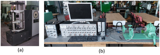
Figure 16.
Experimental equipment: (a) Hydraulic Heckert-EDZ-20S testing machine, (b) Torsion testing device.
Tensile and torsion specimens were prepared from extruded round bars that were 18 mm in diameter. The geometry and dimensions of the specimen are determined by ASTM standards: ASTM E8/E8M-24 Standard Test Methods for Tension Testing of Metallic Materials [23] and SR ISO 7800:2012 Metallic materials—Wire—Simple torsion test [24]. This standard defines the procedures for the torsion testing of wire applications, in the absence of a standard for similar devices. The torsional behavior of material S235JR will be investigated.
Experimental Tests
It is noted that no tests were performed on soft non-metallic materials (silicone), given that these are consumable materials. These materials, at a certain interval of time, depending on wear and modifications made to the device, could be changed because they are fixed on a semi-bracelet with rivets.Tests were performed only on metallic components. To validate the results obtained through simulation, tensile tests (Figure 17) were performed on a Heckert hydraulic press with a maximum force of 200 kN (Heckert-EDZ-20S 200 kN hydraulic testing machine) and torsion tests (Figure 18) were performed on a torsion testing device at room temperature, namely 20 °C.
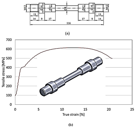
Figure 17.
Tensile test: (a) Dimensions tensile specimen; (b) Tensile test of material S235JR.
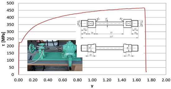
Figure 18.
Conventional characteristic diagram τ–γ, S235JR.
Through tensile testing and the creation of the characteristic curve, several mechanical and elastic properties of the material were identified: proportionality limit, elastic limits, yield strength, tensile strength, elongation at break, and necking at break, which is especially important for the wise utilization of materials and for conducting strength assessments.
With the recorded values, the engineering strain, engineering stress, total elongation, and elongation at break were determined using the following formulas:
where
- —engineering strain [%];
- ∆l—the extension of the gauge length [mm];
- —the original gage length [mm];
- —the final gauge length [mm].
- —engineering stress [MPa];
- P—load [N];
- A0—original cross-sectional area of the gauge length [mm2].
- This property is used to identify the strength of materials.
- —maximum conventional stress, known as the Ultimate Tensile Stress [MPa];
- —maximum load [N];
- A0—original cross-sectional area of the gauge length [mm2].
- The tensile test provides a measure of ductility.
The total elongation was 20%, which includes both elastic and plastic deformation; this is the amount of uniaxial strain at fracture and is depicted as strain at the maximum point. These quantities are usually expressed as percentages.
The reduction is cross-section at fracture (necking at break), Z, where
- —elongation at break [%];
- —the original cross-sectional area of the gauge length [mm2].
- —the final cross-section [mm2];
The longitudinal modulus of elasticity, E, is a property of the material that tells us how easily it can stretch and deform, and is defined as the ratio between tensile stress, σ, and the specific deformation, , provided that the stress does not exceed the proportionality limit:
- E—Young’s modulus (the longitudinal modulus of elasticity) [MPa];
- σ—the ratio of tensile stress [MPa];
- ε—tensile strain [%].
Figure 17 shows the presence of work hardening during the initial stage of deformation. After reaching its ultimate strength of 615 MPa in the second stage, the yield stress subsequently impacts until the fracture happens, at 500 MPa, in the third stage of the deformation.
The transversal deformation modulus, or slip modulus, is an important mechanical property of the material in the case of torsion and shear loads.
The torsion test is a mechanical testing method utilized to analyze the deformation of a specimen through a twisting or rotating action.
The maximum torque value, as shown in Figure 18, that can be applied before specimen failure is 470 MPa. Once the maximum torque is found, a safety factor can be calculated and built into the torque strength specifications of that product. This is the maximum torsional stress that a specimen can sustain before breaking under a torsional load, as well as the specimen’s ultimate strength. Due to torsional movement, shear stress is applied to the specimen’s transverse cross-section. Torsional loading causes an uneven distribution of stress across the specimen’s cross-section, varying from zero at the center to the highest torsional shear stress at the edge.
The shear stress versus strain ratio is used to define elastic shearing. The modulus of elasticity of a material indicates its stiffness when comparing identical products. More force is necessary to deform a structure the stiffer or more rigid it is. When subjected to a torsional moment, the breaking angle reflects a material’s ductility.
For torsion, the equation of the curve (8) represented in Figure 18 obeys Hooke’s law:
where
- τ—Tangential tensile or tangential stress [MPa];
- G—Elasticity transversal modulus [MPa];
- γ—Shear strain [radians].
The angle of twist, the distance along the radius of the shaft, and the length of the shaft all contribute to determining the quantity of shear strain. The formula for shear strain applies to both the elastic and plastic regimes of the material. The shaft length and shear strain are inversely proportional: the longer the shaft, the lower the shear strain.
The transverse deformation modulus, or slip modulus, is a mechanical property of the material that is important in the case of torsion and shear loads.
The conventional characteristic diagram τ–γ is a curve like the tensile test curve. This is characterized by the proportional limit, the elastic limit, the yield point, and the breaking strength. The elastic limit in torsion recorded was 225 MPa; from this point, the material is subject to permanent deformation.
Torsional strength is the maximum amount of torsional stress a material can withstand before failure. The torsional strength recorded during the torsion testing of the specimen was 470 MPa at a shear strain of 1.75 radians. S235JR has good plasticity, toughness, weldability, and cold bending strength and properties.
5. Discussion
At work, problems may arise in terms of occupational diseases or comfort that require a delicate approach; therefore, the presence of differences between human factors and ergonomics, even if the two sciences interact, must be well monitored. In addition, the environment can also favor these conditions through the operating capacity of personnel at work. The most important factors with a negative influence on professional performance are external factors such as noise, vibrations, cold, excessive heat, work–rest cycles, and organizational factors. Thus, ergonomics are closely related to occupational safety [25]. At the workplace, there must be landmarks so that operators can perceive dangers. There must be warning signs, and the control devices must be easy to use, the working posture must be acceptable to the point of comfort, noise and other stressful elements of the environment must be reduced, and there must be good cooperation between the staff and the management of the institution; if there is good administration, then safety at the workplace will increase. Ergonomic measures regarding safety are different from conventional ones. Ergonomics can control safety at work through the attitude of operators, the perception of operators, and their decision-making and behavior in risky situations, but also from the perspective of the materials and the shape of the devices and tools, which was studied in this paper.
In the design of any device, it is necessary to apply and comply with several criteria simultaneously. A work situation in which the production process, ergonomics, or quality are below standards cannot be accepted. All criteria must be at a minimum level of acceptability, as established either by standards or institutions, and correlated with occupational safety standards.
Ergonomics contributes to improving the performance of the system. There are no “conflicts” between ergonomics and productivity [10,11]. Therefore, without optimizing, testing, and analyzing materials regarding the ergonomics and functionality of a device or additional equipment, even if theoretical norms regarding them are known, a study cannot be validated [23,24].
For this reason, in the future, this DIAV device should be implemented in practice and measurements should be performed based on the displacements resulting from the vibrations acting upon it. Measurements will be performed on different groups of machines and equipment, such as pickaxes, rotary hammers, forges, etc. Finally, the performance results can be validated in terms of the answers regarding the assembly, handling, and functionality of the DIAV device, as well as the values of the displacements obtained and their comparison with standards. Regarding the chosen materials, from the experimental tests, it can be observed that the material used in the manufacture of the bracelets resists tensile stresses of a maximum of 615 MPa and tangential stresses up to 470 MPa, which is more than sufficient compared to the demands placed on the device. It is seen that the experimentally obtained results are in accordance with the specialized literature [21,24]. These validate the FEA simulations, as the maximum values of the von Mises stresses obtained from the simulation are much lower, at 27.55 MPa in the hinge area, as shown in Figure 11a and Figure 14a; therefore, the material withstands stresses approximately 2.5 times higher. Also, from the FEA simulations performed, the shock absorber rod is the most affected in terms of deformation, probably due to its small dimensions, up to d = 80 mm. In the torsion test, the experimental data obtained indicated a maximum stress of 470 MPa, double the values obtained in the simulation of 207.2 MPa.
The discussion details two aspects: the bracelet on the hand and the bracelet on the wrist/forearm. We recall that the two bracelets were made from an assembly of two metal semi-bracelets, except for the semi-bracelets on the palm, which were made of a soft material.
By comparing the patented DIBRE device with the new proposed DIAV device, the following can be highlighted:
The patented DIBRE device has a hand bracelet made of leather, which has the disadvantage of not being flexible enough to clench a fist. From this point of view, the proposed DIAV device has the advantage of using softer silicone material.
The two half-bracelets on the wrist/forearm of the DIBRE device are coupled and fixed by screws, which is a disadvantage and means that help is required with assembly/disassembly. By comparison, the two semi-bracelets of the DIAV device are assembled at one end with a hinge and at the other end with a clamp and hole system. The holes are for two positions, which makes them adjustable, giving universality and ensuring a better and more comfortable fit on the hand.
From the point of view of material selection, the tensile strengths are similar, but the cost differs. The material from which DIBRE is made is the non-alloy steel E295, which has better resistance for axes, bare structures, etc., which does not justify its use in the manufacture of bracelets. The S235JR material proposed for the DIAV device is hot-rolled non-alloy structural steel. According to the tests verifying the demands placed on the device, it is a common steel, easy to obtain, and more affordable; however, the need for comfort and safety during its operation must also be considered.
Consequently, to strengthen the justification of this study, Table 7 provides a comparison between the two devices, DIBRE versus DIAV, in terms of ergonomic components and their mounting, and the subsequent explanations justify the choice of materials.
Table 7.
Comparison of DIAV and DIBRE components from the point of view of assembly and ergonomics.
In the paper, it was demonstrated that the primary equipment, named DIBRE and patented and practically realized in a simple form, incorporates a mini attenuator ACE [18] that fulfills its purpose of reducing hand–arm vibrations and vibrations transmitted from vibrating tools at the workplace (Figure 2a–c and Figure 8a,b). This aspect was also validated by the study and its ergonomics were enhanced, so that at this stage, the DIBRE model was transformed into the newly designed DIAV device and validated by material tests (Figure 16, Figure 17 and Figure 18) and FEA simulation (Figure 10, Figure 11, Figure 12, Figure 13, Figure 14 and Figure 15).
Thus, all the experimental results given by the simulations validated the experimental findings regarding the resistance of the materials [26,27,28,29].
With a yield strength of 400 MPa and a tensile strength of 500 MPa obtained experimentally by cold tensile testing, the material subjected to von Mises stresses by simulation was validated. Also, in torsion testing, the material withstands a torsional stress of 470 MPa.
While the specialty literature [3] mentions only gloves as a means of protection against hand vibrations, this work achieved its goal by demonstrating both theoretically through FEA simulation and experimentally with experimental tests on materials that the presence of such a dissipating device mounted on the hand [17] not only reduces the vibrations from the tools and equipment, but also does not influence or limit the operator’s dexterity in the work process. This equipment is ergonomic, easy to assemble, and resistant too; all these are in concordance with standard SR EN 5349-2003 and SR EN 7962 [28,29].
6. Conclusions
This paper analyzed vibration-dissipating equipment from a theoretical and experimental (especially regarding material) point of view. A static analysis of the stresses to which the material of the device’s bracelets was subjected was performed in this article. The FEA results were compared and validated with experimental tests on the tensile and torsional stress of the materials.
The advantages of the proposed DIAV device include the following:
- The semi-bracelet on the hand (palm) is made of soft material (silicone), resistant, interchangeable, and easy to install and adjust. It provides comfort and ensures the maneuverability of the devices and equipment used in the workplace.
- Part of the dissipation equipment is assembled at one end with a hinge, and at the other end with a clamp/claw system and holes. This provides functionality and ease of installation.
- The device fulfills its role as a vibration dissipator, and is both esthetic and easy to use/install.
- The research validated, through the experimental results obtained, the designed model and the methods used. The mechanical stress tests, as well as the resistance tests resulting from the FEA simulation, showed that the DIAV is functionally compliant. The vibrations from the palm semi-bracelet are largely absorbed by the attenuator and are not transmitted further to the forearm/wrist.
- The theoretical FEA models simulated regarding the functionality of the DIAV device, as well as the experimental tests applied to the metallic materials used in this paper for the design phase, are the stresses to which it is exposed. It is worth mentioning that the vibration-dissipating equipment complies with the criteria regarding the weight of this device, reaching a maximum of 500 g, which is acceptable and even desired.
We intend, in the future, to use a multi-criteria approach for the selection of device materials, especially those of the metal bracelets.
Author Contributions
Conceptualization, A.F.C.; methodology, I.M.S.-B.; software, M.C.B.; validation, D.F.; formal analysis, S.H.; investigation, D.F. and M.C.B.; resources, A.F.C. and I.M.S.-B.; writing—original draft preparation, A.F.C. and M.C.B.; writing—review and editing, I.M.S.-B.; visualization, I.M.S.-B. and A.F.C.; and supervision, A.F.C., S.H. and M.C.B. All authors have read and agreed to the published version of the manuscript.
Funding
This research received no external funding.
Institutional Review Board Statement
Not applicable.
Informed Consent Statement
Not applicable.
Data Availability Statement
The original contributions presented in the study are included in the article; further inquiries can be directed to the corresponding author.
Conflicts of Interest
The authors declare no conflicts of interest.
Abbreviations
The following abbreviations are used in this manuscript:
| DIAV | Vibration dissipating equipment was transmitted to the hand from equipment. |
| DIBRE | Initial vibration-dissipating equipment transmitted to the hand from workplace; |
| Wi | kinetic energy (i = 1–4), J; |
| v, vd | total piston velocity, and piston velocity, mm/s; |
| M | moment, Nm; |
| s | piston stroke, mm; |
| R | dynamic element radius, RAD; |
| C | constant; |
| ω | angular velocity, rad/s; |
| me | equivalent mass, kg. |
| ε | engineering strain, %; |
| ∆l | the extension of the gauge length, mm; |
| the original gage length, mm; | |
| the final gauge length, mm; | |
| engineering stress, MPa; | |
| P | load, N; |
| A0 | original cross-sectional area of the gauge length, mm2; |
| maximum conventional stress in known as the Ultimate Tensile Stress, MPa; | |
| maximum load, N; | |
| elongation at break, %; | |
| the final cross-section, mm2; | |
| E | Young’s modulus (the longitudinal modulus of elasticity), MPa; |
| σ | the ratio of tensile stress, MPa; |
| ε | tensile strain, %; |
| τ | Tangential tensile or tangential stress, MPa; |
| G | Elasticity transversal modulus, MPa; |
| γ | shear strain, radians. |
References
- Santos, C.; Gabriel, A.T.; Quaresma, C.; Nunes, I.L. Risk factors, symptoms, and prevalence of lower limb work-related musculoskeletal disorders among orthopedic surgeons. Int. J. Ind. Ergon. 2024, 101, 103597. [Google Scholar] [CrossRef]
- Directive 2002/44/EC of the European Parliament and of the Council of 25 June 2002 on the Minimum Health and Safety Requirements Regarding the Exposure of Workers to the Risks Arising from Physical Agents (Vibration) (Sixteenth Individual Directive within the Meaning of Article 16(1) of Directive 89/391/EEC)—Joint Statement by the European Parliament and the Council. Available online: https://www.ilo.org/media/409921/download (accessed on 31 January 2025).
- Dong, R.G.; Rakheja, S.; Smutz, A.; Schopper, D.W.; Wu, J.Z. Effectiveness of a new method (TEAT) to assess vibration transmissibility of gloves. Int. J. Ind. Ergon. 2002, 30, 33–48. [Google Scholar] [CrossRef]
- Sabino, I.; Fernandes, M.C.; Cepeda, C.; Quaresma, C.; Gamboa, H.; Nunes, I.L.; Gabriel, A.T. Application of wearable technology for the ergonomic risk assessment of healthcare professionals: A systematic literature review. Int. J. Ind. Ergon. 2024, 100, 103570. [Google Scholar] [CrossRef]
- Tosi, F. Design for Ergonomics; EAN 9783030335618; Springer Nature: Berlin/Heidelberg, Germany, 2019; p. 370. [Google Scholar] [CrossRef]
- Tayyari, F.; Smith, J.L. Occupational Ergonomics; EAN 9780412586507; Springer Nature: Berlin/Heidelberg, Germany, 1996; p. 452. [Google Scholar] [CrossRef]
- Salvendy, G.; Karwowski, W. Handbook of Human Factors and Ergonomics, 5th ed.; John Wiley & Sons Inc: Hoboken, NJ, USA, 2021; p. 1600. ISBN 978-1-119-63608-3. [Google Scholar]
- Available online: https://mctr.mec.upt.ro/wp-content/uploads/2019/02/Carte-ergonomie-A-Ergoinginerie.pdf (accessed on 4 April 2025).
- Tian, Y.; Shi, Y.; Wu, Y.; He, W.; Liu, S.; Tao, D. Assessing mouse, trackball, touchscreen and leap motion in ship vibration conditions: A comparison of task performance, upper limb muscle activity and perceived fatigue and usability. Int. J. Ind. Ergon. 2024, 101, 103585. [Google Scholar] [CrossRef]
- Qiu, Y.; Yin, W. Biodynamic responses of lightweight, medium weight and heavyweight subjects in seating posture exposed to single-axis vertical vibration. Int. J. Ind. Ergon. 2024, 102, 103612. [Google Scholar] [CrossRef]
- Chung, J.; Yoon, J.E.; Park, S.; Won, H.; Ha, S. Design development and evaluation of arm movement-assistive suits for lifting and movement for industrial workers considering wearability. Int. J. Ind. Ergon. 2024, 103, 103616. [Google Scholar] [CrossRef]
- Pelmear, P.L.; Taylor, W.; Wasserman, D.E. Limbs Vibration (A Comprehensive Quide for Professional Health Preoccupation); Van Nostran Reinhold: New York, NY, USA, 1998; p. 288. ISBN 9780442012502. Available online: https://catalog.nlm.nih.gov/discovery/fulldisplay?docid=alma997127433406676&context=L&vid=01NLM_INST:01NLM_INST&lang=en&search_scope=MyInstitution&adaptor=Local%20Search%20Engine&tab=LibraryCatalog&query=lds56,contains,Vibration%20--%20adverse%20effects,AND&mode=advanced&offset=80 (accessed on 4 April 2025).
- Revilla, J.A.; Loh, P.; Muraki, S. Effects of two grip force levels and forearm postures on hand-arm transmitted vibration and physiological responses. Eng. Med. Hum. Factors Ergon. Manuf. 2021, 31, 679–692. [Google Scholar] [CrossRef]
- Reinvee, M.; Aia, S.; Pääsuke, M. Ergonomic Benefits of an Angle Grinder with Rotatable Main Handle in a Cutting Task. Engineering. Hum. Factors 2019, 61, 1112–1124. [Google Scholar] [CrossRef] [PubMed]
- Cherian, T.; Rakheja, S.; Bhat, R.B. An analytical investigation of an energy flow divider to attenuate hand- transmitted vibration. Int. J. Ind. Ergon. 1996, 17, 455–467. [Google Scholar] [CrossRef]
- Cristea, A.F.; Nedelcu, M. New Developments of the Hand Arm System. Int. J. Eng. Res. Manag. 2016, 3, 89–96. [Google Scholar]
- Rivaz, H.; Rohling, R. An active dynamic vibration absorber for a hand-held vibro-elastography probe. J. Vib. Acoust. 2007, 129, 101–112. [Google Scholar] [CrossRef]
- Vibration Control. Isolate Unwanted Vibrations Effectively. Available online: https://www.acecontrols.co.uk/uk/products/vibration-control.html (accessed on 11 June 2025).
- Pop (CRISTEA), A.F.; Arghir, M. Vibration Attenuation Device Attached to the Hand-Arm System of the Human. Operator. Patent No. 128,900/2018, 14 July 2000. [Google Scholar]
- Ce Este Ergonomia? Tot ce Trebuie să Știi! Available online: https://kiros.ro/ce-este-ergonomia (accessed on 4 April 2025).
- SR EN 10025:2 2004; Hot Rolled Products of Structural Steels-Part 2: Technical Delivery Conditions for Non-Alloy Structural Steels. UNI: Milano, Italy, 2005.
- SR EN 10088-1:2015; Stainless Steels, Part 1: List of Stainless Steels. UNI: Milano, Italy, 2015.
- ASTM E8/E8M-24; Standard Test Methods for Tension Testing of Metallic Materials. ASTM: West Conshohocken, PA, USA, 2024.
- SR ISO 7800:2012; Metallic Materials—Wire—Simple Torsion Test. ISO: Geneva, Switzerland, 2012.
- Öçal, A.E.; Lekesiz, H.; Çetin, S.T. The Development of an Innovative Occupational Passive Upper Extremity Exoskeleton and an Investigation of Its Effects on Muscles. Appl. Sci. 2023, 13, 6763. [Google Scholar] [CrossRef]
- Sas-Boca, I.M.; Tintelecan, M.; Ilutiu-Varvara, D.A.; Pop, M.; Frunza, D.; Popa, F. Research on the mechanical properties of C45/S235JR multilayer steel systems. Procedia Manuf. 2019, 32, 8–14. [Google Scholar] [CrossRef]
- Yazici, C. Mechanical Properties of S235 Steel Protected with Intumescent Coatings Under High Temperatures: An Experimental Study. Buildings 2024, 14, 1597. [Google Scholar] [CrossRef]
- SR EN 5349-2:2003; Mechanical Vibrations Measurements and Evaluation of Human Exposure at Vibrations Transmitted of hand. UNI: Milano, Italy, 2003.
- SR ISO 7962:1996; Mechanical Vibrations Transmissibility of Mechanical Vibrations of Human body after z Direction. ISO: Geneva, Switzerland, 1996.


Disclaimer/Publisher’s Note: The statements, opinions and data contained in all publications are solely those of the individual author(s) and contributor(s) and not of MDPI and/or the editor(s). MDPI and/or the editor(s) disclaim responsibility for any injury to people or property resulting from any ideas, methods, instructions or products referred to in the content. |
© 2025 by the authors. Licensee MDPI, Basel, Switzerland. This article is an open access article distributed under the terms and conditions of the Creative Commons Attribution (CC BY) license (https://creativecommons.org/licenses/by/4.0/).