Abstract
The mold clamping mechanism is crucial in injection molding machines and significantly influences molding. This research optimizes the Stephenson-chain mechanism with double-toggle effects, particularly focusing on acceleration and driving force. A design incorporating double-toggle effects in the closed position enhances clamping force and ensures safety. For a 6-bar linkage, the Watt-chain mechanism and Stephenson-chain mechanism are available. In this paper, Stephenson-chain mechanisms were selected and subjected to a comprehensive analysis of their kinematic characteristics using vector loop and finite difference methods. The optimal design process included defining the objective function and evaluating the maximum acceleration and force ratio. The results show that the optimal Stephenson-I mechanism achieves a 1.92% increase in the maximum acceleration, and the maximum driving force decreases by 12.34% compared to the optimal Watt-chain mechanism. The Stephenson-II mechanism performs even better, with a 33.94% reduction in maximum acceleration and a 6.81% decrease in maximum driving force compared to the optimal Watt-chain mechanism. The results indicate that the Stephenson-II mechanism outperforms the Stephenson-I mechanism and other existing designs in terms of the maximum acceleration and driving force.
1. Introduction
Injection molding is a critical manufacturing process in modern industry. It is widely used in the automotive, electronic, medical, and consumer product industries. The mold clamping mechanism is a key subsystem that directly affects product quality, production efficiency, and operational safety. The mold clamping mechanism serves three main functions: (1) securely closing and aligning mold halves before injection, (2) maintaining sufficient clamping force during injection and packing to prevent flash and ensure dimensional accuracy, and (3) rapidly opening the mold for part ejection while minimizing acceleration during mold plate movement. Modern manufacturing environments create engineering challenges. Industries demand higher production speeds while requiring lower energy consumption, reduced maintenance costs, and extended equipment life. This creates a fundamental contradiction: high-speed operations typically result in higher acceleration forces, leading to increased vibration, mechanical stress, component wear, and shorter equipment life.
Toggle mechanisms are widely used in industry because they can generate high clamping forces with relatively low driving power and excellent repeatability. These mechanisms require at least one toggle effect at the fully closed position, while double-toggle configurations provide higher clamping force and better operational safety.
Many patents [1,2,3,4,5,6,7,8,9,10,11,12] serve as references for designing clamping mechanisms for injection molding machines, most of which belong to multiple-joint and Watt-chain mechanisms. Huang et al. [13] pioneered genetic algorithm optimization for five-point double-toggle clamping mechanisms, establishing theoretical foundations for mechanism optimization while significantly reducing acceleration and driving force requirements. Chen and Hsieh [14,15,16] introduced innovative designs with dual dead-position configurations, achieving better motion characteristics and enhanced operational stability compared to traditional single dead-position designs. Chang et al. [17] analyzed mechanical errors in nine-link double-toggle mechanisms through combined theoretical and experimental approaches. Le et al. [18] applied computational methods for in-depth studies of the clamping mechanism. He et al. [19] developed comprehensive dynamic models considering inertia and deformation effects. Ho and Nguyen [20] used response surface methodology for geometric optimization of five-point systems. Zhao et al. [21] demonstrated that proper motion adjustment can reduce maximum mold acceleration fluctuations by over 50%. Xie et al. [22] expanded applications to food packaging with electric eight-bar mechanisms.
Despite extensive research on multiple-joint and Watt-chain mechanisms, exploration of alternative mechanisms remains relatively limited. Specifically, although Stephenson-I and Stephenson-II mechanisms are common in general kinematics literature, their feasibility and optimization for clamping system applications have not been systematically explored; the current literature lacks quantitative comparative studies between Stephenson-chain and optimized Watt-chain mechanisms; simultaneously, the potential of alternative mechanisms in reducing motion acceleration has not been thoroughly investigated, while acceleration directly affects machine vibration, component wear, and product quality.
This study addresses these gaps through systematic optimization and comparative analysis of Stephenson-chain mold clamping mechanisms:
- Develop comprehensive kinematic models for Stephenson-I and Stephenson-II mechanisms with double-toggle effects.
- Optimize both configurations for minimum acceleration and driving force through systematic parameter variation.
- Perform quantitative comparative analysis against established optimal Watt-chain mechanisms under identical conditions.
This study addresses these gaps through systematic optimization and comparative analysis of Stephenson-chain mold clamping mechanisms with the objectives outlined above.
The remainder of this paper is organized as follows: Section 2 presents existing mechanism designs that serve as performance benchmarks. Section 3 develops comprehensive kinematic models and analysis methods for Stephenson-chain mechanisms. Section 4 presents the optimization methodology, objective function definition, and optimal design results. Section 5 concludes the paper.
2. Existing Designs
To address the mold clamping requirements in injection molding machines, several mechanism configurations have been developed and implemented. Figure 1 illustrates the four primary feasible mechanisms for mold clamping applications using generalized chain (6, 7) configurations: (a) Watt-chain mechanism, (b) Stephenson-I chain mechanism, (c) Stephenson-II chain mechanism, and (d) multiple-joint mechanism. These mechanisms represent the main structural alternatives available for achieving double-toggle effects in clamping applications.
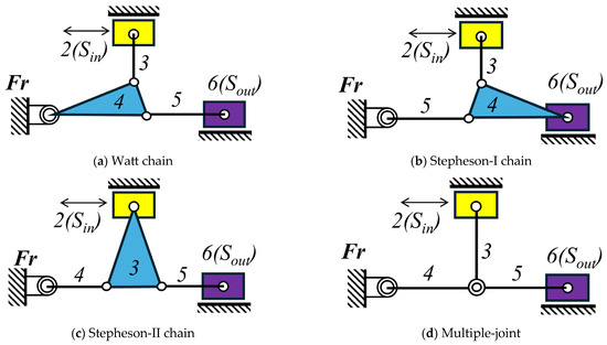
Figure 1.
Feasible mechanisms for mold clamping using generalized chain configurations (6, 7) [14].
2.1. Multiple-Joint Mechanism
Figure 1d shows a multiple-joint mechanism from patent [1], while Figure 2 shows the corresponding mechanism and kinematic skeleton in both the closed and open positions. The mold closing position features double-toggle effects (L1 and L2), as shown in Figure 2a.
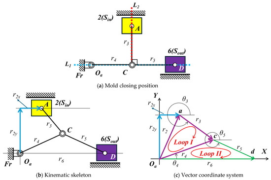
Figure 2.
Kinematic skeletons of a multiple-joint mechanism, constructed based on the descriptions in Patent No. TW 542097 U [1]. The original patent does not provide this schematic; the diagram was interpreted and redrawn by the authors for analysis purposes.
As shown in Figure 2c, the multiple-joint mechanism contains two independent vector loops (Loop I and Loop II), such as Equations (1) and (2).
Here, Loop I is represented by Equation (1), and Loop II is represented by Equation (2). The vectors , , , and represent the links of the mechanism.
The horizontal component X and vertical component Y equations are
Equations (3) and (4) represent the horizontal and vertical components of Loop I, respectively. Equations (5) and (6) represent the horizontal and vertical components of Loop II, respectively. Additionally, , , and correspond to the angles between each link and the positive X-axis.
Assuming mechanical efficiency of 100%, input power equals output power, i.e.,
Here, the and represent input force and input velocity. Similarly, and represent output force and output velocity.
According to research [14,15,16] and based on Equations (3)–(6), if the design parameters are as shown in Table 1 and the input (Sin = 242.25 mm) is driven in 1 s with an MS curve, the output (Sout) displacement is 250 mm, as shown in Figure 3a. Then, the velocity and acceleration can be calculated using the finite difference method, as shown in Figure 3b,c. According to Equation (7) and Figure 3b, the force ratio is calculated and shown in Figure 3d. The peak values for the multi-joint mechanism are summarized in Table 2.

Table 1.
Design parameters of the multiple-joint mechanism.
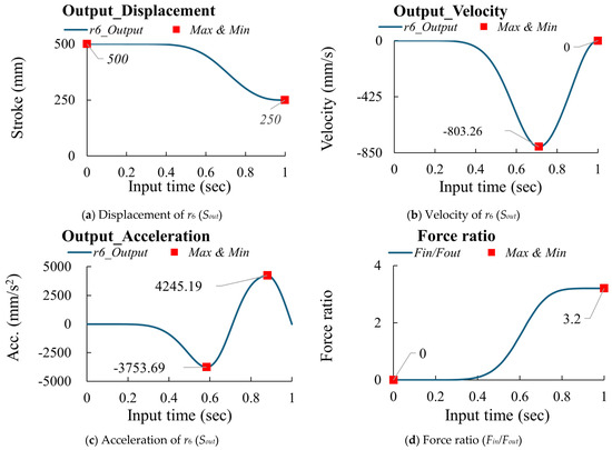
Figure 3.
The kinematic characteristics and force ratio of the multiple−joint mechanism [1].

Table 2.
The peak values of the multi-joint mechanism.
2.2. Optimal Watt-Chain Mechanism
Figure 1a shows a Watt-chain mechanism from patent [2], while Figure 4 shows the corresponding mechanism and kinematic skeleton in both the closed and open positions. The mold closing position features double-toggle effects (L1 and L2), as shown in Figure 4a.
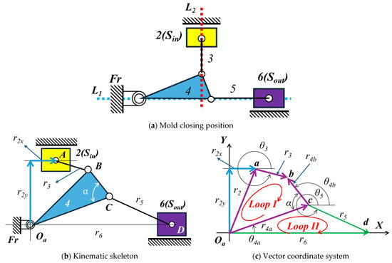
Figure 4.
Kinematic skeletons of the Watt−chain mechanism, constructed based on the descriptions in Patent No. TW M257273 [2]. The original patent does not provide this schematic; the diagram was interpreted and redrawn by the authors for analysis purposes.
As shown in Figure 4c, the Watt-chain mechanism contains two independent vector loops (Loop I and Loop II), such as Equations (8) and (9).
Here, Loop I is represented by Equation (8), and Loop II is represented by Equation (9), where the vectors , , , , , and represent the links of the mechanism.
The horizontal component X and vertical component Y equations are
Equations (10) and (11) represent the horizontal and vertical components of Loop I, respectively. Equations (12) and (13) represent the horizontal and vertical components of Loop II, respectively. Additionally, , , and , correspond to the angles between each link and the positive X-axis.
According to research [16], Table 3 shows the design parameters of the optimal Watt-chain mechanism. If the input (Sin = 276.29 mm) is driven in 1 s with an MS curve, Figure 5a–c show the displacement, velocity, and acceleration of the output (Sout), and Figure 5d shows the corresponding force ratio. The peak values for the optimal Watt-chain mechanism are summarized in Table 4.

Table 3.
Design parameters of the optimal Watt−chain mechanism.
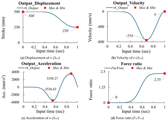
Figure 5.
The kinematic characteristics and force ratio of the optimal Watt−chain mechanism [2].

Table 4.
The peak values of the optimal Watt−chain mechanism.
3. Dimension Synthesis and Kinematic Analysis
3.1. Design Requirements
Given the kinematic requirements and space constraints of the injection molding machine, the design criteria are outlined as follows:
- (1)
- The output displacement must be 250 mm (Sout = 250 mm) within 1 s of moving from the mold closing to the open position.
- (2)
- (3)
- (4)
- The input (Sin) displacement must be such that .
3.2. Stephenson−I Mechanism
Figure 6 illustrates the kinematic skeleton and vector coordinate system of the Stephenson-I mechanism.

Figure 6.
Mold clamping mechanism of the Stephenson−I mechanism.
As shown in Figure 6b, the Stephenson−I mechanism contains two independent vector loops (Loop I and Loop II), such as Equations (14) and (15).
Here, Loop I is represented by Equation (14), and Loop II is represented by Equation (15), where the vectors , , , , , and represent the links of the mechanism.
The horizontal component X and vertical component Y equations are
Equations (16) and (17) represent the horizontal and vertical components of Loop I, respectively. Equations (18) and (19) represent the horizontal and vertical components of Loop II, respectively. Additionally, , , , and correspond to the angles between each link and the positive X-axis.
According to the design parameters shown in Table 5, the input (Sin) is driven in 1 s with an MS curve. The output (Sout) displacement can be calculated based on Equations (16)–(19). Then, the velocity and acceleration can be calculated using the finite difference method, and Equation (7) can calculate the driving force. The analysis results are shown in Figure 7. The peak values for the Stephenson-I mechanism are summarized in Table 6.

Table 5.
Design parameters of Stephenson−I mechanism.
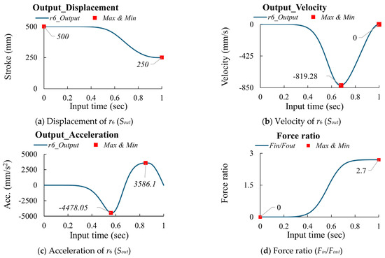
Figure 7.
The kinematic characteristics and force ratio of the Stephenson−I mechanism.

Table 6.
The peak values of the Stephenson−I mechanism.
3.3. Stephenson−II Mechanism
Figure 8 illustrates the kinematic skeleton and vector coordinate system of the Stephenson−II mechanism.

Figure 8.
Mold clamping mechanism of the Stephenson−II mechanism.
As shown in Figure 8b, the Stephenson−II mechanism contains two independent vector loops (Loop I and Loop II), such as Equations (20) and (21).
Here, Loop I is represented by Equation (20), and Loop II is represented by Equation (21), where the vectors , , , , , and represent the links of the mechanism.
The horizontal component X and vertical component Y equations are
Equations (22) and (23) represent the horizontal and vertical components of Loop I, respectively. Equations (24) and (25) represent the horizontal and vertical components of Loop II, respectively. Additionally, , , , and correspond to the angles between each link and the positive X-axis.
According to the design parameters shown in Table 7, the input (Sin) is driven in 1 s using an MS curve. The output (Sout) displacement can be calculated based on Equations (22)–(25). Then, the velocity and acceleration can be calculated using the finite difference method, and Equation (7) can calculate the driving force. The analysis results are shown in Figure 9. The peak values for the Stephenson-II mechanism are summarized in Table 8.

Table 7.
Design parameters of Stephenson−II mechanism.
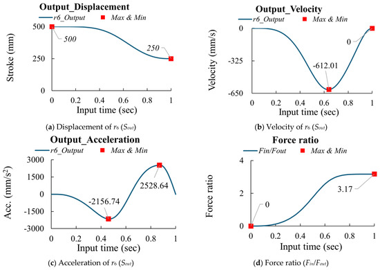
Figure 9.
Kinematic characteristics and force ratio of the Stephenson-II mechanism.

Table 8.
The peak values of the Stephenson-II mechanism.
4. Optimal Design of Stephenson-Chain Double-Toggle Mechanism
Based on the analysis results, the Stephenson-chain mechanism is optimally designed (double-toggle effect, L1 and L2). Figure 10 and Figure 11 depict the Stephenson-I and -II mechanisms in closed and open positions.
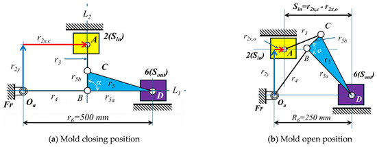
Figure 10.
The skeleton for Case I (Stephenson−I mechanism).
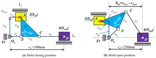
Figure 11.
The skeleton for Case II (Stephenson−II mechanism).
4.1. Optimal Design Process
The optimal design process for the Stephenson−chain double−toggle mechanism can be summarized as follows:
- (a)
- The design for Case I (Stephenson−I mechanism) includes two design variables, r3 and α, while the remaining parameters, r2y and r2x,c, can be calculated. Similarly, the design for Case II (Stephenson−II mechanism) includes two design variables, r2y and r4, while the remaining parameters r2x,c can be calculated.
- (b)
- A diagrammatic method is used to determine the position of r2 when the mold is closed and open. Therefore, the stroke of the input is given by Sin = r2x,c−r2x,o.
- (c)
- The MS curve consists of symmetric sinusoidal segments that provide continuous acceleration profiles, thereby enhancing operational stability and extending the service life of mechanism components, as shown in Figure 12. Therefore, the input slider is driven according to a Modified Sine (MS) motion law with a cycle time of 1 s (β = 1 s). The mathematical formulation of this motion profile is defined as follows:
- (1)
- For
- (2)
- For
- (3)
- For
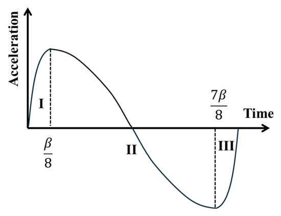
Figure 12.
The modified sinusoidal curve (MS).
- (d)
- The output displacement Sout is derived from the kinematic Equations (14)–(25) based on the input MS motion. Velocity and acceleration are computed via the finite difference method, and the force ratio is determined by Equation (7).
- (e)
- Repeat steps a to d to evaluate all design combinations and identify the optimal design with minimum objective function value.
The optimization strategy employed in this study utilizes systematic parameter variation combined with exhaustive search within defined bounds. The methodology involves the following:
- Parameter Space Discretization: Discrete parameter ranges are established based on design constraints, with systematic increments for each design variable:
- (1)
- Stephenson−I mechanism: α varies in 10° increments, r3 varies in 10 mm increments;
- (2)
- Stephenson−II mechanism: r2y varies in 10 mm increments, r4 varies in 5 mm increments.
- 2.
- Exhaustive Evaluation: All feasible parameter combinations within the defined bounds are systematically evaluated to ensure comprehensive coverage of the design space.
- 3.
- Global Optimum within Discrete Space: Since exhaustive search is performed within the discretized parameter space, the identified solution represents the global minimum within the investigated parameter ranges. However, it should be noted that this does not guarantee global optimality over the entire continuous parameter space.
Therefore, the results presented in this study represent the optimal designs within the investigated parameter ranges rather than absolute global optima.
4.2. Objective Function
The objective function Fo is defined as
In Equation (35), W1 is the weighting coefficient for |Amax| set to 2, and W2 is the weighting coefficient for (Fin/Fout)max set to 1. Since acceleration directly affects the shaking force generated during mechanism motion, the weighting coefficient is set to W1 > W2. To consider the influence of force ratio on the objective function and reduce the disparity between |Amax| and (Fin/Fout)max, a factor of 1000 is multiplied by the W2 weighting value. By substituting |Amax| and (Fin/Fout)max into this equation, the minimum value of the objective function Fo represents the optimal solution.
4.3. Optimal Design
4.3.1. Case I (Stephenson−I Mechanism)
Based on the above steps, Table 9 presents the parameter variations for Case I (Stephenson−I mechanism). The results indicate that Design No. 23 is the optimal design among the 23 experiments, achieving Fo = 9313.1, |Amax| = 3626.55 mm/s2, and (Fin/Fout)max = 2.06. Figure 13 depicts the kinematic skeleton of the optimized design for Case I, while Figure 14 shows the kinematic characteristics and force ratio curves of the output slider. Based on the above results, the optimal design of the Stephenson-I mechanism is better than the optimal design of the Watt−chain mechanism. Although the maximum acceleration |Amax| increased by 1.9%, the maximum force ratio (Fin/Fout)max decreased by 12.3%.

Table 9.
Design results based on Case I (Stephenson−I mechanism).
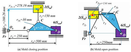
Figure 13.
The optimal design for Case I (Stephenson−I mechanism).
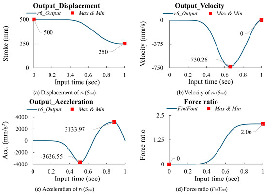
Figure 14.
The kinematic curves of the optimized design for Case I (Stephenson−I mechanism).
4.3.2. Case II (Stephenson−II Mechanism)
Based on the above steps, Table 10 presents the parameter variations for Case II (Stephenson−II mechanism). The results indicate that Design No. 12 is the optimal design among the 15 experiments, achieving Fo = 6891.32, |Amax| = 2350.66 mm/s2, and (Fin/Fout)max = 2.19. Figure 15 depicts the kinematic skeleton of the optimized design for Case II, while Figure 16 shows the kinematic characteristics and force ratio curves of the output slider. Based on the above results, the optimal design of the Stephenson−II mechanism is better than the optimal design of the Watt−chain mechanism. The maximum acceleration |Amax| decreased by 33.9%, and the maximum force ratio (Fin/Fout)max decreased by 6.8%.

Table 10.
Design results based on Case II (Stephenson−II mechanism).
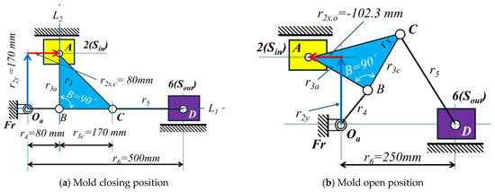
Figure 15.
The optimal design for Case II (Stephenson−II mechanism).
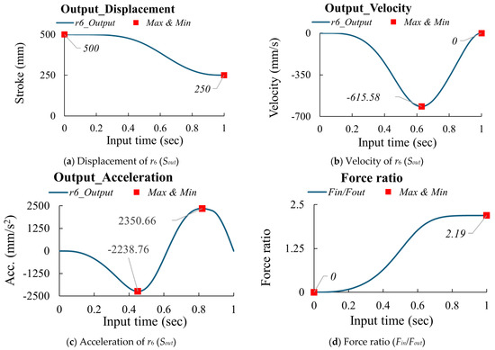
Figure 16.
The kinematic curves of the optimized design for Case II (Stephenson−II mechanism).
4.3.3. Comparison Between Optimal Designs
Based on the above results, Table 11 compares the optimal designs.

Table 11.
The comparison between optimal designs.
5. Conclusions
This study proposes an optimization procedure for Stephenson−chain double−toggle clamping mechanisms and provides the corresponding optimal designs. According to Table 11, the following is concluded:
- Compared to the optimal Watt−chain mechanism [2], the optimal Stephenson−I (Case I) increased the maximum acceleration |Amax| by 1.9% and decreased the maximum force ratio (Fin/Fout)max by 12.3%.
- Compared to the optimal Watt−chain mechanism [2], the optimal Stephenson−II (Case II) decreased the maximum acceleration |Amax| by 33.9% and decreased the maximum force ratio (Fin/Fout)max by 6.8%.
- Compared to the optimal Stephenson−I mechanism (Case I), the optimal Stephenson−II mechanism (Case II) decreased the maximum acceleration |Amax| by 35.2% and increased the maximum force ratio (Fin/Fout)max by 4.9%.
Overall, the optimal Stephenson−II mechanism (Case II) exhibited superior maximum acceleration and driving force characteristics compared to other designs. The comparative analysis and optimization results presented in this study establish design guidelines for selecting between Stephenson−I, Stephenson−II, and Watt−chain mechanisms based on specific operational priorities, providing manufacturers with quantitative criteria for choosing the most suitable mechanism in injection molding applications.
Author Contributions
Methodology, T.-H.C.; formal analysis, T.-H.C. and P.-C.L.; software, P.-C.L.; data curation, T.-H.C.; writing—original draft preparation, P.-C.L.; writing—review and editing, T.-H.C.; project administration, T.-H.C.; funding acquisition, T.-H.C. and P.-C.L. All authors have read and agreed to the published version of the manuscript.
Funding
This research was funded by Chumpower Machinery Co., Ltd., grant number 109AF076.
Institutional Review Board Statement
Not applicable.
Informed Consent Statement
Not applicable.
Data Availability Statement
The data presented in this study are available from the corresponding author, P.-C. Lai, upon reasonable request.
Acknowledgments
The authors thank Zheng Sheng-Wen for his assistance in this research.
Conflicts of Interest
The founders had no role in the design of the study, in the collection, analysis, or interpretation of data, in the writing of the manuscript, or in the decision to publish the results.
References
- Lai, G.-S.; Su, W.-F.; Lin, G.-S. Mold Locking Mechanism for Servo Driving Type Injection Molding Machine. TW 542097 U, 11 July 2003. [Google Scholar]
- Jiang, F.-C. Driving Apparatus for Controlling Mold Open/Close of Plastic Forming Machine. TW M257273, 21 February 2005. [Google Scholar]
- Chang, W.-T.; Wu, L.-I. Ten-Link Type Double-Toggle Mold Clamping Mechanisms. TW I382913, 16 March 2012. [Google Scholar]
- Mathy, J.J.M.; Oles, P.M.; Fiorani, D.N. Modular Clamp Station. US 8454342 B2, 19 September 2013. [Google Scholar]
- Chen, Y.-Y.; Qin, J.-C. Mold-Locking Device for Mold. TW I537121, 11 June 2016. [Google Scholar]
- Lin, W.-Y.; Zhang, Y.-C.; Xiao, Y.-J. Five-Point Double-Toggle Mold Clamping Mechanism of Injection Molder. TW M541943, 21 May 2017. [Google Scholar]
- Ching, K.Y. Electric Tooling Locking Apparatus for Plastic Injection Machine. TWI600520 B, 1 October 2017. [Google Scholar]
- Ogiso, T.; Morita, H. Injection Molding Machine. TWI594867 B, 11 August 2017. [Google Scholar]
- Sugahara, K. Machine Base for Injection Molding Machine. US 10875225 B2, 29 December 2020. [Google Scholar]
- Okamoto, A.; Miyamoto, K. Mold Clamp Control Method for Injection Molding Machine Having Toggle-Type Mold Clamping Mechanism. US10981314B2, 20 April 2021. [Google Scholar]
- Uchiyama, T.; Nishimura, N.; Senga, M. Die Clamping Device for Injection Molding Machine. US20230405898A1, 21 December 2023. [Google Scholar]
- Tan, H.C.; Tan, O.E. Toggle Mechanism for Closing of a Mold in a Molding Machine. US11931939B1, 19 March 2024. [Google Scholar]
- Huang, M.-S.; Lin, T.-Y.; Fung, R.-F. Key Design Parameters and Optimal Design of a Five-Point Double-Toggle Clamping Mechanism. Appl. Math. Model. 2011, 35, 4304–4320. [Google Scholar] [CrossRef]
- Chen, T.-H.; Hsieh, L.-C. The Design of Mold Clamping Mechanisms with Two Dead-Position Configurations. Adv. Technol. Innov. 2019, 5, 33. [Google Scholar] [CrossRef]
- Hsieh, L.C.; Chen, T.H.; Lai, P.C. Dimensional Synthesis and Kinematic Analysis of Mold Clamping Mechanism with Double Toggle Effects at Clamped Position. Appl. Mech. Mater. 2020, 900, 27–34. [Google Scholar]
- Hsieh, L.-C.; Chen, T.-H.; Lai, P.-C.; Zheng, S. Optimal Design on Watt-Chain Double-Toggle Mold Clamping Mechanism for Injection Molding Machine. Sci. Prog. 2021, 104 (Suppl. S3), 00368504211041488. [Google Scholar] [CrossRef] [PubMed]
- Chang, W.-T.; Lee, W.-I.; Hsu, K.-L. Analysis and Experimental Verification of Mechanical Errors in Nine-Link Type Double-Toggle Mold/Die Clamping Mechanisms. Appl. Sci. 2021, 11, 832. [Google Scholar] [CrossRef]
- Le, V.-D.; Hoang, V.-T.; Tao, Q.-B.; Benabou, L.; Tran, N.-H.; Luu, D.-B.; Park, J.M. Computational Study on the Clamping Mechanism in the Injection Molding Machine. Int. J. Adv. Manuf. Technol. 2022, 121, 7247–7261. [Google Scholar] [CrossRef]
- He, Z.; Zhai, F.; Zhang, Y.; Wang, W.; Li, D.; Zhu, N.; Ruan, J. Research on Dynamics Model of the Motion Clamping Mechanism in Injection Molding Machines Addressing Inertia and Deformation. J. Manuf. Process. 2024, 119, 987–1004. [Google Scholar] [CrossRef]
- Ho, T.B.; Nguyen, H.L. Geometric Optimization of the Five-Point Double-Toggle System for the Clamping Unit of an Injection Molding Machine with the Response Surface Method. Eng. Technol. Appl. Sci. Res. 2024, 14, 18415–18422. [Google Scholar] [CrossRef]
- Zhao, N.; Xu, Z.; Shan, Y.; Zhou, H.; Huang, X. The Constant/Variable Kinematics Adjustment of the Crosshead and the Mold’s Stability Management in Injection Molding. Int. J. Adv. Manuf. Technol. 2024, 133, 901–912. [Google Scholar] [CrossRef]
- Xie, Z.; Chen, X.; Xu, Z. Motion and Force Analysis of Mold Open-Closing Mechanism with Electric Eight-Bar for Food Packaging Thermoforming Machine. Food Mach. 2024, 40, 90–94. [Google Scholar] [CrossRef]
Disclaimer/Publisher’s Note: The statements, opinions and data contained in all publications are solely those of the individual author(s) and contributor(s) and not of MDPI and/or the editor(s). MDPI and/or the editor(s) disclaim responsibility for any injury to people or property resulting from any ideas, methods, instructions or products referred to in the content. |
© 2025 by the authors. Licensee MDPI, Basel, Switzerland. This article is an open access article distributed under the terms and conditions of the Creative Commons Attribution (CC BY) license (https://creativecommons.org/licenses/by/4.0/).