
Denoised Improved Envelope Spectrum for Fault Diagnosis of Aero-Engine Inter-Shaft Bearing


Abstract
1. Introduction
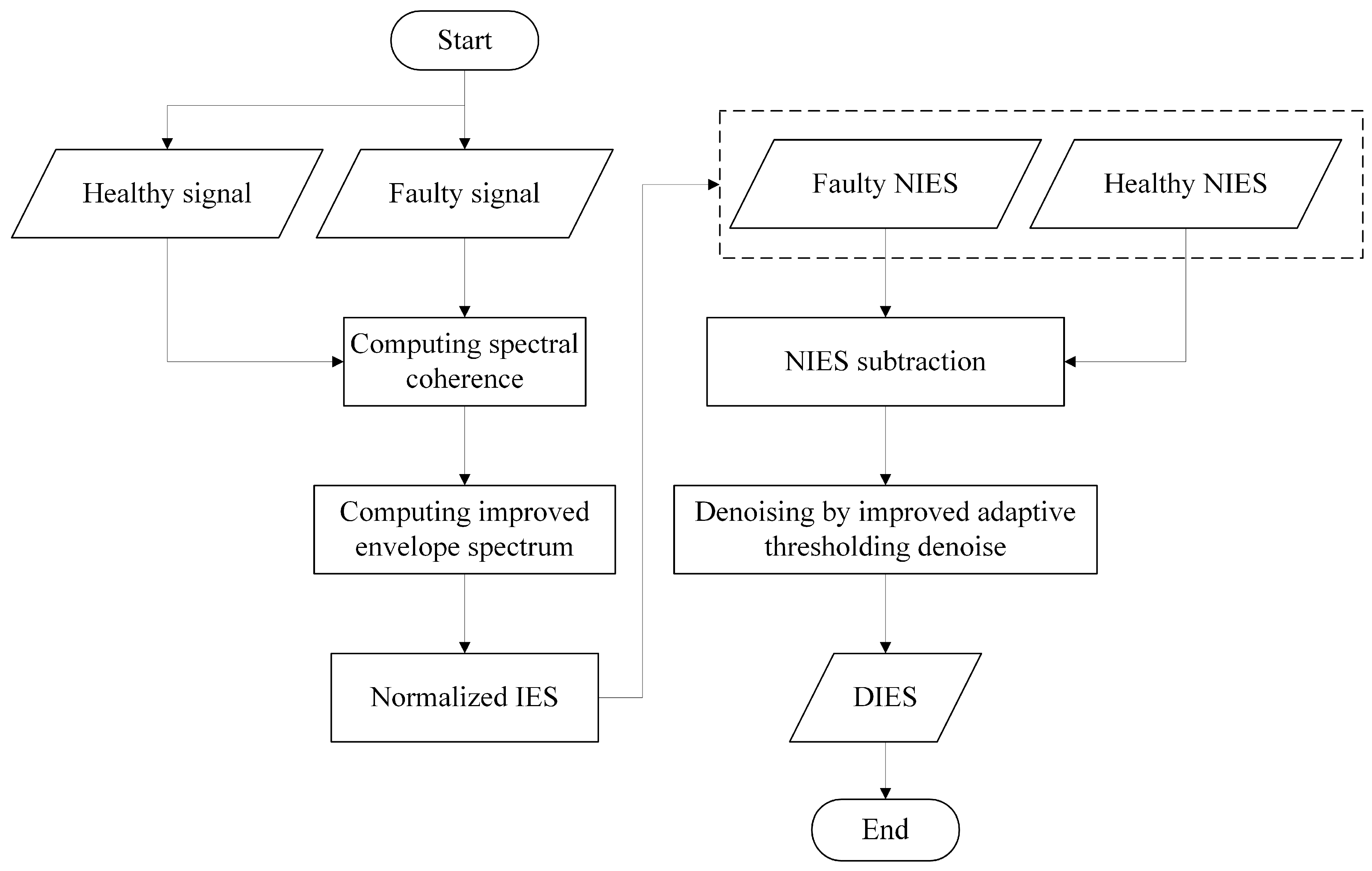
2. Methods
2.1. IES Algorithm
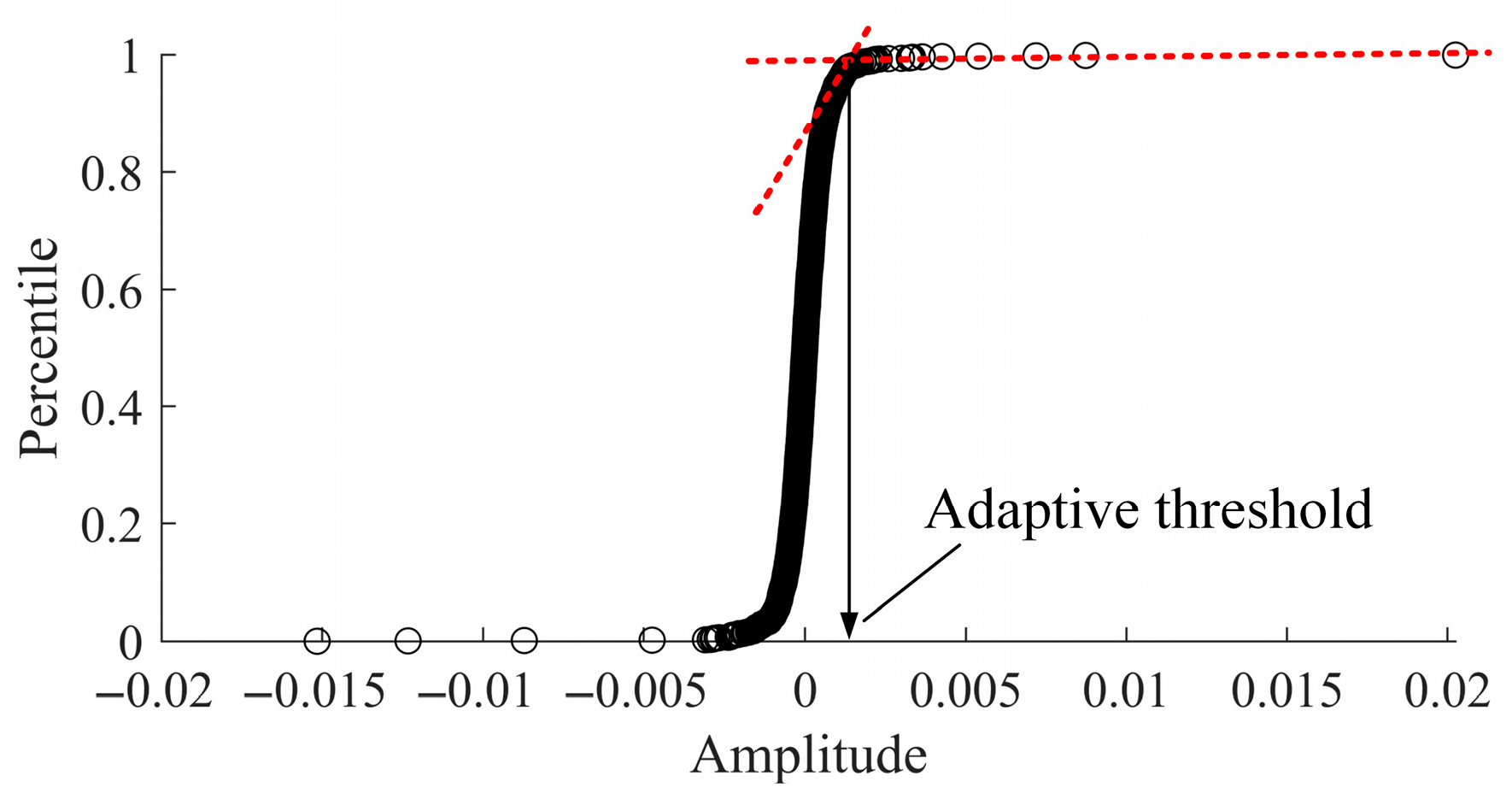
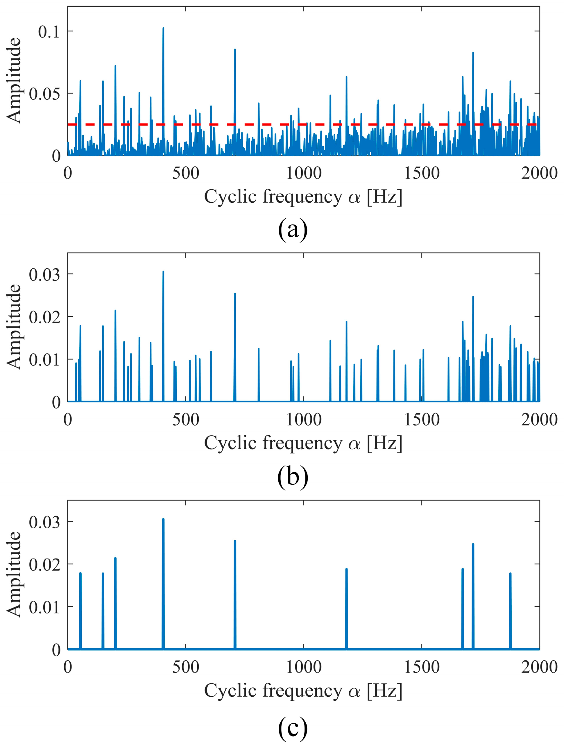
2.2. Improved Adaptive Denoising for Subtracted NIES
- (1)
- Compute amplitude percentile points of all the spectral lines of the ;
- (2)
- The first D% of the data is selected in descending order;
- (3)
- Compute line-based change point using the selected data;
- (4)
- Calculate the threshold for denoising.
2.3. The Proposed DIES for Improving SC Analysis
3. Experimental Validation
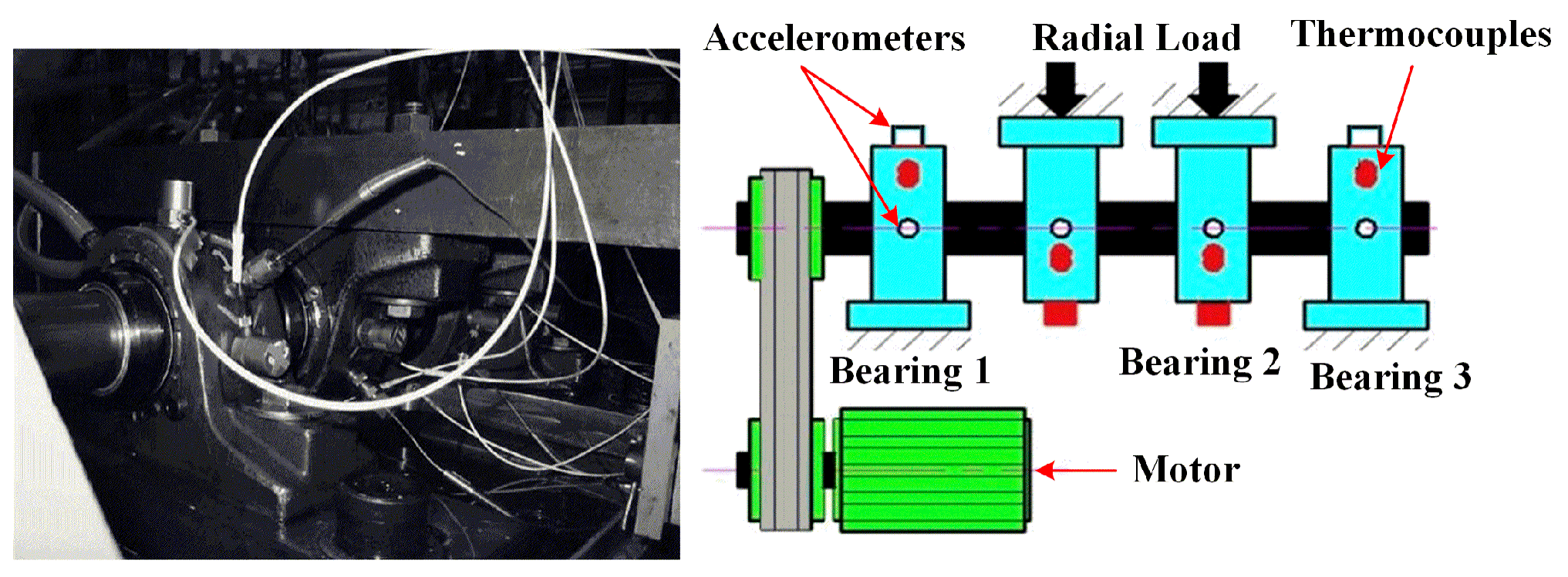
3.1. Case Study on Incipient Bearing Fault Diagnosis
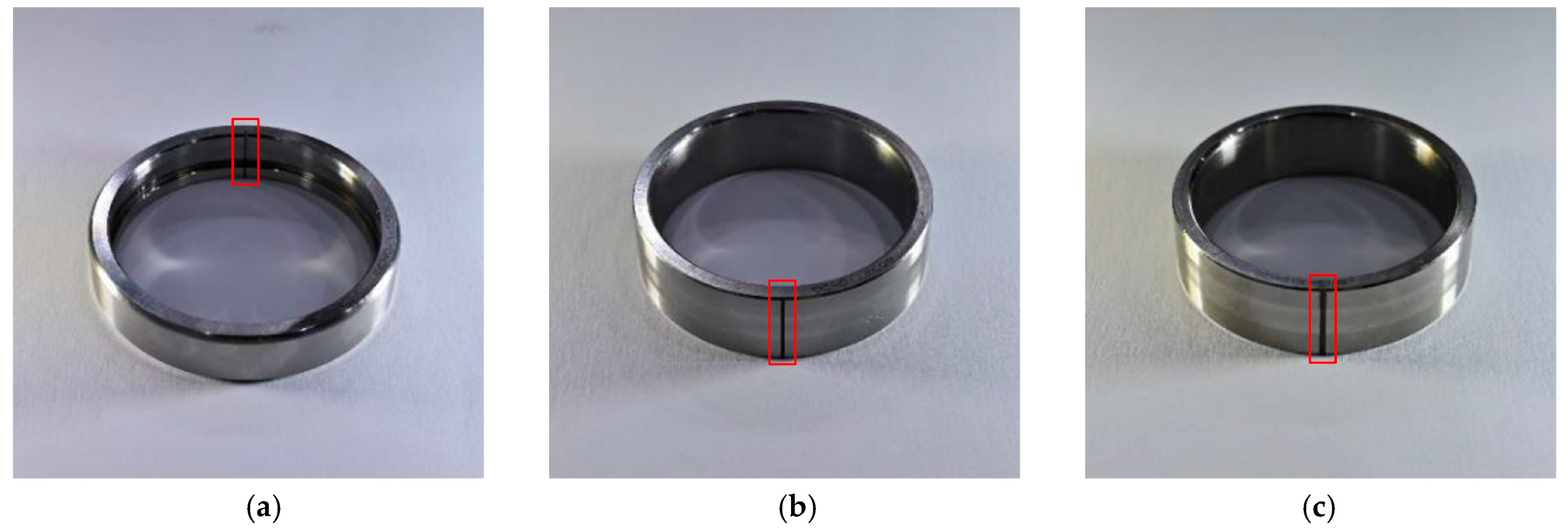
3.2. Case Study on HIT Inter-Shaft Bearing Fault Diagnosis
4. Conclusions
Author Contributions
Funding
Institutional Review Board Statement
Informed Consent Statement
Data Availability Statement
Acknowledgments
Conflicts of Interest
Abbreviations
| CCF | Cross-Correlation Function |
| CFSS | Cyclic Frequency Spectrum Slice |
| DIES | Denoised Improved Envelope Spectrum |
| EES | Enhanced Envelope Spectrum |
| FCF | Fault Characteristic Frequency |
| FFT | Fast Fourier Transform |
| HP | High Pressure |
| IES | Improved Envelope Spectrum |
| IESFOgram | Improved Envelope Spectrum via Feature Optimization-gram |
| INS | Improved Noise Subtraction |
| ITD | Intrinsic Time-Scale Decomposition |
| LP | Low Pressure |
| NIES | Normalized Improved Envelope Spectrum |
| SC | Spectral Correlation |
| SCoh | Spectral Coherence |
| SES | Squared Envelope Spectrum |
| SK-ES | Spectral Kurtosis–Envelope Spectrum |
| SVD | Singular Value Decomposition |
| VMD | Variational Mode Decomposition |
| WT | Wavelet Transform |
References
- Hou, L.; Yi, H.; Jin, Y. Inter-Shaft Bearing Fault Diagnosis Based on Aero-Engine System: A Benchmarking Dataset Study. JDMD 2023, 2, 228–242. [Google Scholar] [CrossRef]
- Kumar, N.; Satapathy, R.K. Bearings in Aerospace, Application, Distress, and Life: A Review. J. Fail. Anal. Prev. 2023, 23, 915–947. [Google Scholar] [CrossRef]
- Lu, Z.; Zhong, S.; Chen, H.; Wang, X.; Han, J.; Wang, C. Nonlinear Response Analysis for a Dual-Rotor System Supported by Ball Bearing. Int. J. Non-Linear Mech. 2021, 128, 103627. [Google Scholar] [CrossRef]
- Liu, P.; Wang, L.; Zhang, C.; Zheng, D. Research Status and Development Trend of Condition Monitoring on Main-Shaft Bearings Used in Aircraft Engines. J. Aerosp. Power 2022, 37, 330–343. [Google Scholar] [CrossRef]
- Chen, G.; He, Z.; Wei, X.; Yu, P. Vibration Analysis of Peeling Fault of Intermediate Bearing Outer Ring Based on Whole Aero-Engine. J. Aerosp. Power 2020, 35, 658–672. [Google Scholar]
- Yu, M.; Fang, M.; Chen, W.; Cong, H. Compound Faults Feature Extraction of Inter-Shaft Bearing Based on Vibration Signal of Whole Aero-Engine. J. Vib. Control. 2023, 29, 51–64. [Google Scholar] [CrossRef]
- Liao, M.; Ma, Z.; Liu, Y.; Wang, D. Fault Characteristics and Diagnosis Method of Intershaft Bearing in Aero-Engine. J. Aerosp. Power 2013, 28, 2752–2758. [Google Scholar] [CrossRef]
- Ai, Y.; Tian, B.; Tian, J.; Sun, Z.; Wang, Z. Frequency Band Optimization of Morlet Complex Wavelet and Its Application in Fault Diagnosis of Inter-Shaft Bearing. J. Aerosp. Power 2013, 28, 2752–2758. [Google Scholar]
- Gryllias, K.C.; Antoniadis, I. A Peak Energy Criterion (P. E.) for the Selection of Resonance Bands in Complex Shifted Morlet Wavelet (CSMW) Based Demodulation of Defective Rolling Element Bearings Vibration Response. Int. J. Wavelets Multiresolution Inf. Process. 2009, 7, 387–410. [Google Scholar] [CrossRef]
- Dragomiretskiy, K.; Zosso, D. Variational Mode Decomposition. IEEE Trans. Signal Process. 2014, 62, 531–544. [Google Scholar] [CrossRef]
- Yan, R.; Shang, Z.; Xu, H.; Wen, J.; Zhao, Z.; Chen, X.; Gao, R.X. Wavelet Transform for Rotary Machine Fault Diagnosis:10 Years Revisited. Mech. Syst. Signal Process. 2023, 200, 110545. [Google Scholar] [CrossRef]
- Wang, J.; Zhan, C.; Li, S.; Zhao, Q.; Liu, J.; Xie, Z. Adaptive Variational Mode Decomposition Based on Archimedes Optimization Algorithm and Its Application to Bearing Fault Diagnosis. Measurement 2022, 191, 110798. [Google Scholar] [CrossRef]
- Pan, X.; Yu, M.; Meng, G.; Chen, W. A Study on the Diagnosis of Compound Faults in Rolling Bearings Based on ITD-SVD. J. vibroeng. 2021, 23, 587–602. [Google Scholar] [CrossRef]
- Frei, M.G.; Osorio, I. Intrinsic Time-Scale Decomposition: Time-Frequency-Energy Analysis and Real-Time Filtering of Non-Stationary Signals. Proc. R. Soc. A Math. Phys. Eng. Sci. 2007, 463, 321–342. [Google Scholar] [CrossRef]
- Yi, H.; Hou, L.; Gao, P.; Chen, Y. Nonlinear Resonance Characteristics of a Dual-Rotor System with a Local Defect on the Inner Ring of the Inter-Shaft Bearing. Chin. J. Aeronaut. 2021, 34, 110–124. [Google Scholar] [CrossRef]
- Lin, R.; Hou, L.; Zhong, S.; Chen, Y. Nonlinear Vibration and Stability Analysis of a Dual-Disk Rotor-Bearing System under Multiple Frequency Excitations. Nonlinear Dyn. 2024, 112, 12815–12846. [Google Scholar] [CrossRef]
- Randall, R.; Antoni, J.; Chobsaard, S. The Relationship between Spectral Correlation and Envelope Analysis in the Diagnostics of Bearing Faults and Other Cyclostationary Machine Signals. Mech. Syst. Signal Process. 2001, 15, 945–962. [Google Scholar] [CrossRef]
- Antoni, J. Cyclic Spectral Analysis of Rolling-Element Bearing Signals: Facts and Fictions. J. Sound Vib. 2007, 304, 497–529. [Google Scholar] [CrossRef]
- Antoni, J.; Xin, G.; Hamzaoui, N. Fast Computation of the Spectral Correlation. Mech. Syst. Signal Proc. 2017, 92, 248–277. [Google Scholar] [CrossRef]
- Chen, B.; Zhang, W.; Gu, J.X.; Song, D.; Cheng, Y.; Zhou, Z.; Gu, F.; Ball, A. Product Envelope Spectrum Optimization-Gram: An Enhanced Envelope Analysis for Rolling Bearing Fault Diagnosis. Mech. Syst. Signal Proc. 2023, 193, 110270. [Google Scholar] [CrossRef]
- Abboud, D.; Antoni, J. Order-Frequency Analysis of Machine Signals. Mech. Syst. Signal Proc. 2017, 87, 229–258. [Google Scholar] [CrossRef]
- Abboud, D.; Elbadaoui, M.; Smith, W.A.; Randall, R.B. Advanced Bearing Diagnostics: A Comparative Study of Two Powerful Approaches. Mech. Syst. Signal Process. 2019, 114, 604–627. [Google Scholar] [CrossRef]
- Mauricio, A.; Smith, W.A.; Randall, R.B.; Antoni, J.; Gryllias, K. Improved Envelope Spectrum via Feature Optimisation-Gram (IESFOgram): A Novel Tool for Rolling Element Bearing Diagnostics under Non-Stationary Operating Conditions. Mech. Syst. Signal Proc. 2020, 144, 106891. [Google Scholar] [CrossRef]
- Chen, B.; Cheng, Y.; Zhang, W.; Gu, F.; Mei, G. Optimal Frequency Band Selection Using Blind and Targeted Features for Spectral Coherence-Based Bearing Diagnostics: A Comparative Study. ISA Trans. 2022, 127, 395–414. [Google Scholar] [CrossRef] [PubMed]
- Ma, X.; Ma, H.; Qin, H.; Guo, X.; Zhao, C.; Yu, M. Nonlinear Vibration Response Characteristics of a Dual-Rotor-Bearing System with Squeeze Film Damper. Chin. J. Aeronaut. 2021, 34, 128–147. [Google Scholar] [CrossRef]
- Kumar, A.; Tang, H.; Vashishtha, G.; Xiang, J. Noise Subtraction and Marginal Enhanced Square Envelope Spectrum (MESES) for the Identification of Bearing Defects in Centrifugal and Axial Pump. Mech. Syst. Signal Proc. 2022, 165, 108366. [Google Scholar] [CrossRef]
- Antoni, J. Cyclostationarity by Examples. Mech. Syst. Signal Proc. 2009, 23, 987–1036. [Google Scholar] [CrossRef]
- Cheng, Y.; Wang, S.; Chen, B.; Mei, G.; Zhang, W.; Peng, H.; Tian, G. An Improved Envelope Spectrum via Candidate Fault Frequency Optimization-Gram for Bearing Fault Diagnosis. J. Sound Vib. 2022, 523, 116746. [Google Scholar] [CrossRef]
- Hou, B.; Wang, D. Optimal Noise Subtraction-Based Fault Components Extraction for Machinery Fault Diagnosis. IEEE Trans. Instrum. Meas. 2023, 72, 3517210. [Google Scholar] [CrossRef]
- Lee, J.; Qiu, H.; Yu, G.; Lin, J.; Rexnord Technical Services. Bearing Data Set, IMS, University of Cincinnati, NASA Ames Prognostics Data Repository 2007. Available online: https://www.kaggle.com/datasets/vinayak123tyagi/bearing-dataset (accessed on 21 July 2025).
- Wei, Y.; Li, Y.; Xu, M.; Huang, W. A Review of Early Fault Diagnosis Approaches and Their Applications in Rotating Machinery. Entropy 2019, 21, 409. [Google Scholar] [CrossRef] [PubMed]
- Liao, M.; Ma, Z.; Deng, W. Vibration Analysis on Turbofan Engine Intershaft Bearing with Outer Race Defect. J. Aerosp. Power 2011, 26, 2422–2426. [Google Scholar] [CrossRef]


| Structural Parameter | Value |
| Number of rolling elements | 16 pc. |
| Rolling element diameter | 8.4 mm |
| Diameter of pitch circle | 71.5 mm |
| Nominal pressure angle | 15.17° |
| OperationParameter | Frequency |
| Rotation frequency | 33 Hz |
| Outer race fault frequency | 236.4 Hz |
| Inner race fault frequency | 296 Hz |
| Rolling element fault frequency | 139.6 Hz |
| Cage fault frequency | 14.8 Hz |
| Parameter | Value |
|---|---|
| Number of rolling elements | 15 pc. |
| Diameter of inner ring | 30 mm |
| Diameter of outer ring | 65 mm |
| Diameter of pitch circle | 55 mm |
| Rolling element diameter | 7.5 mm |
| Nominal pressure angle | 0° |
| Method | Whether Fault-Related Frequency Components Are Extracted | Whether Interference Frequency Components Are Effectively Eliminated | Whether Noise Components Are Effectively Eliminated |
|---|---|---|---|
| SK-ES | IMS-Yes; HIT-No | No | No |
| IES | Yes | No | No |
| ITD-SVD | Yes | No | Yes |
| DIES | Yes | Yes | Yes |
Disclaimer/Publisher’s Note: The statements, opinions and data contained in all publications are solely those of the individual author(s) and contributor(s) and not of MDPI and/or the editor(s). MDPI and/or the editor(s) disclaim responsibility for any injury to people or property resulting from any ideas, methods, instructions or products referred to in the content. |
© 2025 by the authors. Licensee MDPI, Basel, Switzerland. This article is an open access article distributed under the terms and conditions of the Creative Commons Attribution (CC BY) license (https://creativecommons.org/licenses/by/4.0/).
Share and Cite
Li, D.; Chen, L.; Zhou, H.; Tang, J.; Zhao, X.; Xie, J. Denoised Improved Envelope Spectrum for Fault Diagnosis of Aero-Engine Inter-Shaft Bearing. Appl. Sci. 2025, 15, 8270. https://doi.org/10.3390/app15158270
Li D, Chen L, Zhou H, Tang J, Zhao X, Xie J. Denoised Improved Envelope Spectrum for Fault Diagnosis of Aero-Engine Inter-Shaft Bearing. Applied Sciences. 2025; 15(15):8270. https://doi.org/10.3390/app15158270
Chicago/Turabian StyleLi, Danni, Longting Chen, Hanbin Zhou, Jinyuan Tang, Xing Zhao, and Jingsong Xie. 2025. "Denoised Improved Envelope Spectrum for Fault Diagnosis of Aero-Engine Inter-Shaft Bearing" Applied Sciences 15, no. 15: 8270. https://doi.org/10.3390/app15158270
APA StyleLi, D., Chen, L., Zhou, H., Tang, J., Zhao, X., & Xie, J. (2025). Denoised Improved Envelope Spectrum for Fault Diagnosis of Aero-Engine Inter-Shaft Bearing. Applied Sciences, 15(15), 8270. https://doi.org/10.3390/app15158270