Article

A Low-Cost IoT-Based Bidirectional Torque Measurement System with Strain Gauge Technology

1
Faculty of Mechanical Engineering, Politehnica University of Timisoara, M. Viteazu Bv. No 1, 300222 Timisoara, Romania
2
Faculty of Electronics, Telecommunication and Information Technologies, Politehnica University of Timisoara, V. Parvan Bv, No. 2, 300223 Timisoara, Romania
*
Author to whom correspondence should be addressed.
Appl. Sci. 2025, 15(15), 8158; https://doi.org/10.3390/app15158158
Submission received: 22 June 2025 / Revised: 19 July 2025 / Accepted: 20 July 2025 / Published: 22 July 2025
(This article belongs to the Section Electrical, Electronics and Communications Engineering)

Abstract

The scope of this paper is the development of a cost-effective wireless torque measurement system for vehicle drivetrain shafts. The prototype integrates strain gauges, an HX711 conditioner, a Wemos D1 Mini ESP8266, and a rechargeable battery directly on the rotating shaft, forming a self-contained sensor node. Calibration against a certified dynamometric wrench confirmed an operating span of ±5–50 N·m. Within this range, the device achieved a mean absolute error of 0.559 N·m. It also maintained precision better than ±2.5 N·m at 95% confidence, while real-time data were transmitted via Wi-Fi. The total component cost is below EUR 30 based on current prices. The novelty of this proof-of-concept implementation demonstrates that reliable, IoT-enabled torque sensing can be realized with low-cost, readily available parts. The paper details assembly, calibration, and deployment procedures, providing a transparent pathway for replication. By aligning with Industry 4.0 requirements for smart, connected equipment, the proposed torque measurement system offers an affordable solution for process monitoring and predictive maintenance in automotive and industrial settings.

1. Introduction

Torque measurement plays a pivotal role in automotive engineering, machine diagnostics, and industrial process control, enabling engineers to optimize performance, ensure safety, and implement predictive maintenance strategies [1,2,3,4]. In automotive drivetrains, for example, real-time torque data can reveal inefficiencies, mechanical failures, or abnormal operating conditions before they escalate into costly repairs or hazardous situations. The system specifically targets the absence of low-cost, bidirectionally calibrated torque sensors for drivetrain shafts in small laboratories and resource-constrained factories, where high-cost commercial solutions remain prohibitive. The key innovation lies in the systematic integration of commercially available components with robust bidirectional calibration methodology and wireless data transmission, specifically designed for rotating shaft applications. The mounting methodology for rotating shafts and the comprehensive polynomial calibration approach for both clockwise and counterclockwise torque measurement represent the primary technical contributions. The development of this torque sensor system addresses the need for affordable, bidirectional torque measurement in automotive drivetrains. While commercial sensors provide high accuracy, their cost and proprietary calibration protocols limit accessibility for research and small-scale industrial applications. This work introduces an alternative Internet of Things (IoT)-enabled platform that integrates low-cost components (e.g., 24-bit signal amplifier HX711, ESP8266) with robust polynomial calibration, enabling real-time monitoring at under EUR 30. All electronic sub-assemblies were acquired as off-the-shelf components from Chinese marketplace resellers, a procurement route that ensured rapid availability and kept costs low. The system’s design prioritizes ease of assembly and adaptability, making it suitable for evaluating drivetrain performance in resource-constrained environments. If validated, such sensors could extend to permanent vehicle integration, supporting traction control and predictive maintenance systems akin to tire pressure monitoring solutions. Unlike many commercial torque transducers that replace a section of the drivetrain with a proprietary shaft and flange set, the proposed sensor is bonded directly to the existing shaft and therefore requires no cutting, machining, or bespoke adapters. This drop-in installation greatly simplifies retrofitting and preserves the dynamic balance of the drivetrain.
Despite these advances, practical challenges remain. Calibration procedures must rigorously address nonlinearity, hysteresis, and the need for traceability to reference standards. The presence of additional torque components due to mechanical couplings or installation effects can introduce systematic errors that must be compensated, either through detailed physical modeling or data-driven approaches such as neural networks. Robust calibration protocols, utilizing dedicated calibration devices and cross-validation against reference instruments, are essential for ensuring the reliability and reproducibility of torque measurements in real-world environments. Principal error contributors include gauge-mounting misalignment, mounting-induced bending moments, thermo-elastic drift, and humidity-induced adhesive creep; these factors are mitigated through symmetry verification, real-time temperature correction, and conformal coating. Dynamic uncertainties arising from shaft vibration and parasitic bending add ≤1% FS at 1 kHz, but finite-element compensation and anti-alias filtering limit the residual error to <0.3% FS [5,6,7,8].
Furthermore, most published solutions focus solely on unidirectional torque measurement and often lack comprehensive calibration and error analysis, limiting their applicability in scenarios involving reversible or oscillatory loads. There is a clear need for practical, affordable, and statistically robust systems capable of accurate bidirectional (clockwise and counterclockwise) torque measurement, with transparent calibration and error compensation procedures.
This paper addresses these limitations by presenting the practical development, assembly, and calibration of a wireless, IoT-enabled torque measurement system. The system is designed for straightforward installation on rotating shafts. Calibration is performed using a certified dynamometric wrench, with the relationship between sensor output and applied torque established through high-order polynomial regression analysis to accurately capture the sensor’s nonlinear response. The calibration procedure yields a set of polynomial coefficients that define the conversion from digital output to applied torque across the full measurement range. Error metrics such as mean absolute error and standard deviation are reported to ensure transparency and reproducibility. The methodology is specifically designed to be transparent and verifiable, addressing the need for practical calibration in reversible and oscillatory load environments.
The scope of this paper is the development of a cost-effective, wireless, and bidirectional torque measurement system. The novelty of this work lies in the integration of strain gauges, open-source electronics, and robust calibration within a single, IoT-enabled platform. This approach provides a verifiable pathway for implementing reliable wireless torque measurement in automotive, industrial, and research contexts, bridging the gap between laboratory-grade accuracy and practical field deployment.

2. Related Work

Recent advances in IoT-enabled torque sensing and machine learning-based calibration have opened new possibilities for cost-effective measurement systems [9,10]. Recent advances in IoT-enabled torque sensing highlight the role of modern modulation schemes in boosting throughput and link robustness. Building on this trend, the present design adopts standard 2.4 GHz Wi-Fi, while future iterations will incorporate adaptive modulation similar to the OFDM-based strategies reported for industrial IoT gateways and the fine-time-measurement (FTM) techniques validated in vehicular telemetry at rotational speeds above 1000 rotations per minute [9,10]. These studies demonstrate that dynamic selection of sub-carriers and precise timing protocols can lower the packet error rate below 1% and cut latency to sub-10 ms, metrics that are essential for distributed, multi-sensor torque monitoring in harsh electromagnetic environments [9,10]. Neural network-based calibration methods have shown significant improvements in accuracy for force–torque sensors [11,12,13], while wireless sensor networks have enabled distributed monitoring in industrial applications. However, most existing DIY solutions [14,15] focus on simple servo torque measurement or lack comprehensive bidirectional calibration and error analysis.
Compared to existing low-cost solutions, the presented system uniquely combines bidirectional polynomial calibration, IoT connectivity, and comprehensive error analysis within a single platform, addressing the specific needs of automotive drivetrain applications.
However, the evolution of torque measurement techniques has been driven by the need to address dynamic errors and environmental influences, which can significantly affect measurement accuracy [3,5,6,16]. Strain-gauge-based systems, while widely adopted, are particularly susceptible to such errors, as highlighted in recent studies [6,17].
The present sensor was chosen to address the lack of access to expensive dynamometric stands and high-end torque transducers in many academic and industrial laboratories. A low-cost, field-installable alternative therefore enables routine drivetrain testing under strict budgets, and once validated, it could permanently remain on vehicles to assist traction, braking, and stability control.
The integration of wireless sensor networks and industrial IoT has enabled the development of distributed, real-time monitoring systems for mechanical parameters, including torque [7]. These systems leverage wireless communication protocols and modular architectures to facilitate remote data acquisition and analytics, supporting the digital transformation of manufacturing environments envisioned by Industry 4.0. Smart, connected sensors are now fundamental components in enabling adaptive control, digital twins, and data-driven decision-making in modern factories [7]. Despite these advances, ensuring measurement accuracy and reliability in such systems remains a major challenge, particularly when these systems are subjected to varying operational and environmental conditions.
Recent research has made significant strides in addressing these challenges. Unlike earlier low-cost or unidirectional solutions, this work demonstrates a bidirectional, IoT-enabled torque transducer that achieves ±2.5 N·m accuracy for under EUR 30 through open-source hardware and polynomial calibration. For example, Yu et al. [3] developed and calibrated a high-precision torque measurement system for industrial robot reducers. Their work systematically addressed the effects of additional torque introduced by the transmission chain, such as friction and elastic deformation, which can introduce systematic errors into the measurement process. To compensate for these errors, the authors implemented an improved particle swarm optimization and Levenberg–Marquardt algorithm-based radial basis function neural network, allowing for effective error compensation beyond traditional linear calibration. The experimental results demonstrated that, after calibration and neural network-based compensation, the system achieved a measurement accuracy of 0.1% of full scale, highlighting the effectiveness of advanced hybrid calibration and compensation methods in demanding industrial applications.
Gillot et al. demonstrated that wireless strain gauge systems can reliably monitor pavement deformation under hydraulic loading, achieving measurement accuracy comparable to traditional wired sensors [18]. These systems offer the added benefits of simplified installation and robust data transmission, even when exposed to temperature fluctuations and dynamic loading scenarios. The findings highlight the practical viability of wireless strain gauge technology for large-scale infrastructure monitoring, supporting the transition toward more efficient and scalable sensing networks in civil engineering applications.
In the field of robotic actuation, integrated torque sensors have been used to investigate intrinsic friction and torque ripple, particularly in applications requiring bidirectional torque measurement [19]. After the implementation of compensation strategies, the root mean square error of the torque measured by the joint sensor was reduced to 11% relative to an external reference, demonstrating the effectiveness of calibration and compensation protocols [19]. This work underscores the necessity of bidirectional calibration for robotic and automotive systems that experience frequent load reversals and dynamic operational conditions.
Advancements in sensor calibration have led to the development of universal, on-site calibration models for six-axis force–torque (FT) sensors, enabling compensation for environmental and installation effects using only the sensor’s own data. Experimental results show that these models can address parameters such as center of mass, crosstalk, and inclination, thereby improving measurement reliability in field deployments without the need for laboratory recalibration [20]. Such approaches facilitate broader and more flexible application of FT sensors in diverse and unpredictable environments.
Other researchers have explored alternative approaches to torque measurement and calibration. Bosmans et al. [21] proposed a virtual torque sensing approach for wind turbine gearboxes using fiber-optic strain sensors mounted on ring gears. Their method leveraged operational deflection shape analysis to isolate torque-related deformations, achieving an average normalized root mean square error of 0.7%. This technique provided a robust, cost-effective alternative to traditional shaft-mounted sensors, suitable for dynamic, harsh operational environments. Zhang et al. [22] proposed a practical calibration method for mechanical torque measurement on wind turbine drive trains using electrical power measurements instead of direct mechanical calibration, thereby reducing calibration costs while maintaining traceability to international standards.
Uncertainty analysis and robust calibration protocols are also critical. Fidelus et al. [23] conducted a comprehensive uncertainty analysis of a 5 MN·m torque transducer using Monte Carlo simulations and fuzzy set theory, revealing a relative expanded uncertainty below 0.06% in the upper torque range. Voronin et al. [24] developed a strain-gauge-based telemetry system for real-time torque monitoring on rolling mill spindles, achieving a measurement error of 0.2% after calibration and demonstrating significant benefits in reducing downtime and extending equipment lifespan.
The use of advanced signal processing and sensor fusion techniques for fault detection and quantitative diagnosis in rotating machinery is also gaining traction. Yu and Yu [25] proposed a method for diagnosing shaft misalignment based on speed signal analysis and neural network modeling, demonstrating the growing role of data-driven approaches in enhancing the reliability and diagnostic capabilities of sensor systems.

3. Materials and Methods

The developed torque measurement system, depicted in Figure 1, consists of strain gauges Rg1, Rg2, Rg3, Rg4 positioned at ±45° angles relative to the shaft axis, forming two pairs on opposite sides; a signal conditioning module specifically designed for strain gauge/loadcell applications; a microcontroller; a DC-DC converter; and a rechargeable battery. The strain gauge configuration maximizes sensitivity to torsional strain while compensating for temperature and bending effects [26].
The torque measurement approach is based on the application of strain gauges to a rotating shaft, following procedures described by Popelka et al. and Lopot et al. [27,28]. For multi-axis measurement considerations, design principles from Ehsani et al. are referenced [29].
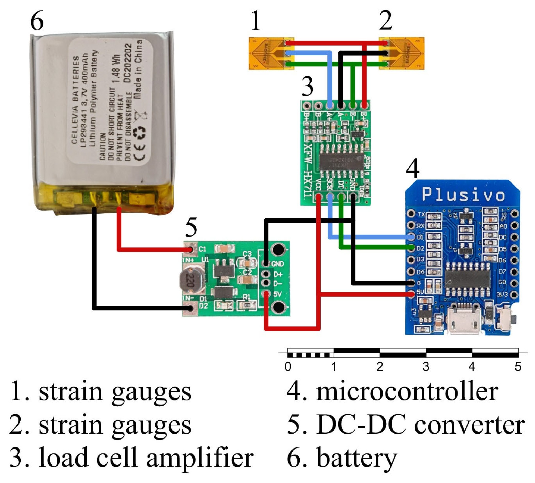
The core of the measurement system consists of four BF350−3HA−E foil strain gauges (1,2), an HX711 precision load cell amplifier (3), a Wemos D1 Mini ESP8266 microcontroller (4), a 400 mAh lithium polymer (Li−Po) battery (6), and a DC-DC step-down converter (5) as illustrated in Figure 2 [30]. All components, made in China, were chosen based on cost, availability, and compatibility with open-source development platforms. The BF350-3HA-E strain gauges are widely used for force and deformation measurements. Their small size and high sensitivity make them suitable for mounting on rotating shafts. Each BF350-3HA−E strain gauge consists of two sensitive elements arranged at ±45 degrees relative to the longitudinal axis. The HX711 is a conditioning signal module that includes a voltage regulator, a programmable gain voltage amplifier, a 24−bit analog−to−digital converter (ADC), and a serial data transmission peripheral. It is designed for load cells, weigh scales, and industrial control applications. It provides the necessary amplification and digitization of the strain gauge output. The Wemos D1 Mini ESP8266 is a compact, Wi-Fi-enabled microcontroller that supports Arduino programming. The 400 mAh Li-Po battery, regulated by a DC-DC converter, ensures stable operation for extended periods. The chosen shaft for torque measurement has a diameter of 10 mm and a length of 600 mm. The shaft surface was prepared by sanding and cleaning with isopropyl alcohol to ensure optimal adhesion of the strain gauges. Gauges were bonded to the shaft using a two-part epoxy adhesive, following the manufacturer’s recommended procedure and the strain gauge application methods described by Chahmi and Lopot et al. [26,28]. After curing, the gauges were connected in a full Wheatstone bridge configuration using fine copper wire and solder, as depicted in Figure 2.
The completed bridge was tested for continuity and baseline resistance, and the output wires were routed through a flexible cable to the amplifier and microcontroller assembly. Data acquisition was performed using an Arduino-based system, which has been shown to be effective for both laboratory and field applications [17,31]. For alignment and calibration procedures, methods from Szybicki et al. were adapted [32,33,34]. Firmware for the ESP8266 was developed using the Arduino IDE. The code handled initialization, periodic reading of the HX711 output, and digital filtering. Calibration was performed using a certified dynamometric wrench, which applied known torque values to the shaft in increments of 5 N·m, from 5 N·m up to 50 N·m. For each applied torque, multiple digital output readings from the HX711 were recorded.
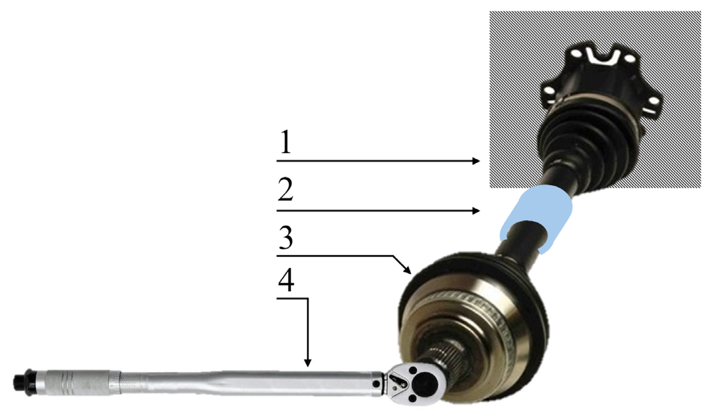
As shown in Figure 3, the half shaft (3), on which the torque sensor (2) is mounted, is rigidly clamped at one end (1). Using the certified torque wrench (4), a known torque is applied to the shaft. This setup enables precise calibration of the sensor output against reference torque values, ensuring accurate and repeatable measurement performance. Figure 3 highlights the practical integration of the sensor and the calibration process.
The process was repeated five times per torque value to ensure repeatability in both directions (clockwise and counterclockwise). The average recorded data for each increment was plotted, and a fifth-order polynomial regression was performed to establish the nonlinear relationship between the digital output and the applied torque. The resulting polynomial coefficients were programmed into the ESP8266 firmware, enabling real-time conversion of raw sensor readings into torque values. Regression analysis was used to validate the polynomial model’s ability to capture the sensor’s bidirectional response, with error metrics such as mean absolute error (MAE) and standard deviation (SD) calculated for each calibration point. This approach aligns with best practices for torque sensor calibration in nonlinear systems, as detailed in recent literature [3,35,36,37,38]. The polynomial coefficients and uncertainty analysis follow guidelines for high-precision metrology outlined in the guidelines in SMITH and the work of Zhang et al. [7,22,39,40,41].
The Wheatstone bridge configuration provides inherent thermal compensation, as mentioned in the system description. The HX711 module demonstrates relatively stable performance with temperature variations within its specified operating range [8]. However, long-term stability requires periodic recalibration, the frequency of which depends on operating conditions and measurement requirements.
Currently, filtering techniques are not implemented in the presented results. However, advanced filtering methods such as Kalman filtering [42] can significantly improve measurement stability and precision. Future implementations may incorporate artificial intelligence-based algorithms to reduce or eliminate the need for frequent recalibration.

4. Results

The IoT-based torque measurement system was calibrated and validated using both clockwise and counterclockwise torque applications. This comprehensive approach ensures the sensor’s response is well-characterized for bidirectional torque, which is essential for many practical applications such as drivetrain analysis and reversible mechanical systems [3,21,34]. Calibration was performed by applying known torque values to the instrumented shaft in both directions using a certified dynamometric wrench [5,43]. For each torque increment, the sensor’s raw digital outputs were recorded. The raw digital output of the sensor was used directly for calibration and measurement calculations. This approach is more suitable for continuous torque monitoring, where it is not practical to return to zero after every measurement. It is recommended to periodically perform a zeroing procedure, either after a certain number of measurements or after a set number of operating hours, to compensate for potential drift and offset that may accumulate over time. Table 1 presents the averaged digital measured sensor values corresponding to each applied torque level, for both clockwise and counterclockwise directions.
A nonlinear relationship was observed between the applied torque and the net sensor value in both directions. This bidirectional calibration enables the device to accurately measure both positive (clockwise) and negative (counterclockwise) torques using a fifth-order polynomial regression model. All calibration and regression formulas used in this work are based on the procedures described in ISO 376:2011 [44], adapted for nonlinear calibration.
The relationship between the applied torque (T) and the digital sensor value (DV) was established using fifth-order polynomial regression, as shown in Equation (1) [5]:
T i = a 0 + a 1 D V i + a 2 D V i 2 + a 3 D V i 3 + a 4 D V i 4 + a 5 D V i 5 + ε i
where T i is the applied torque, D V i is the averaged digital value, a 0 to a 5 are the polynomial coefficients, and ε i is the residual error.
The coefficients a 0 to a 5 were determined using the ordinary least squares (OLS) method in matrix form, as presented in Equation (2) [45]:
a ^   =   X t · X 1 · X t · T
where X is the Vandermonde matrix is constructed from the digital values (DV), and T is the vector of measured torque values. This approach minimizes the sum of squared differences between the measured and indicated torque values, providing the best-fit polynomial coefficients for the calibration curve.
The goodness of fit was quantified using the coefficient of determination (R2) as defined in Equation (3) [46]. This is the classic definition of the coefficient of determination, which quantifies the proportion of variance in the dependent variable (torque) that is predictable from the independent variable (sensor output). This is a standard statistical metric.
R 2 = 1 i = 1 n T i T i ^ 2 i = 1 n T i T ¯ 2
where T i is the measured torque for the i -th data point, T i ^ is the indicated torque from the regression model, T ¯ is the mean of measured torque values, and n is the number of data points. The R 2 value indicates how well the regression model fits the observed data. An R 2 value close to 1 signifies that the model accounts for nearly all the variability in the measured torque, confirming the appropriateness of the polynomial model for this calibration. For the obtained values, R 2 = 0.99916, confirming excellent agreement between the polynomial fit and the experimental data, thus validating the model’s reliability.
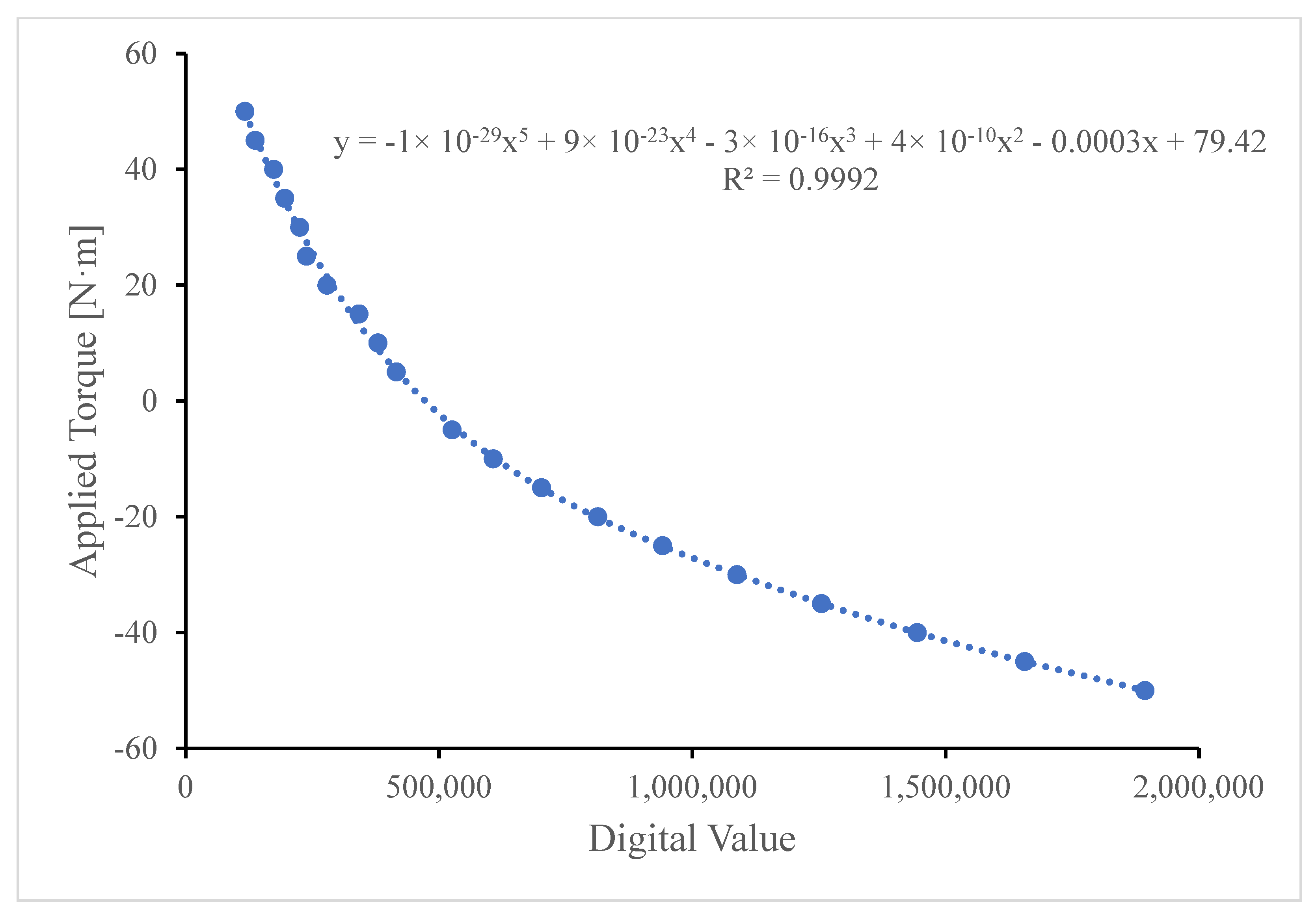
The calibration curve was constructed by plotting the mean digital sensor values against the applied torque for each calibration point. A fifth-order polynomial regression was applied to the data, and the resulting fit is shown as a dotted line in Figure 4. The equation of the polynomial and the R2 value are displayed on the graph. The high R2 value confirms the suitability of the polynomial model for accurate calibration across the full range of applied torque.
The mean absolute error (MAE) is the standard way to express the average magnitude of errors in a set of predictions, without considering their direction, as calculated by Equation (4) [47]:
MAE = 1 n i = 1 n T i T i ^
The MAE provides a single value that summarizes the average magnitude of the errors between the indicated and actual torque values, regardless of direction. Intuitively, the MAE tells us how far, on average, the measurement system’s readings deviate from the true applied torque. Thus, a lower MAE means that the indicated torque values are, on average, closer to the actual torque, directly reflecting higher measurement accuracy.
Table 2 presents the absolute error for each calibration point across the tested torque range. The mean absolute error (MAE) calculated over all measurements was 0.559 N·m. This value represents the average deviation between the sensor output and the reference torque, providing a quantitative measure of the system’s overall accuracy.
Torque was applied in both clockwise (positive values) and counterclockwise (negative values) directions to evaluate the sensor’s bidirectional accuracy. Reporting MAE for both directions allows for the assessment of any asymmetry or hysteresis in the sensor’s response, which is a common characteristic in strain-gauge-based torque transducers. The observed MAE of 0.559 N·m reflects average accuracy, while the maximum precision for 95% probability reaches ±2.5 N·m across the tested range. This performance is consistent with the requirements for laboratory and industrial torque measurements using strain-gauge-based sensors. The detailed reporting of absolute errors at each calibration point, alongside the overall MAE, provides transparency and allows for the identification of any systematic trends or direction-dependent effects.
Repeatability was assessed by calculating the standard deviation (σ) of repeated measurements at each torque level, as defined in Equation (5) [48]:
σ = 1 n 1 i = 1 n T i T ¯ 2
where xi represents repeated measurements and x ¯ is the mean of the repeated measurements. This metric quantifies the precision of the system by indicating how closely grouped the measurements are for the same applied torque. However, it does not reflect closeness to the true value (accuracy), which is instead evaluated through the MAE.
Table 3 presents the statistical analysis of the calibration data for the torque measurement system. For each applied torque value, the observed average torque was calculated from multiple repeated measurements. The standard deviation quantifies the repeatability of the system at each torque level, while the final column displays twice the standard deviation, corresponding to an approximate 95% confidence interval for the repeated measurements (assuming a normal distribution). This analysis provides a transparent assessment of the measurement uncertainty and repeatability across the full bidirectional torque range. Notably, the standard deviation remains below 1.25 N·m for all calibration points, confirming the system’s high precision and suitability for applications requiring reliable bidirectional torque monitoring.
The key calibration parameters are now described by the coefficients of the fifth-order polynomial regression, which accurately models the nonlinear relationship between the digital sensor output and the applied torque. The goodness of fit is quantified by the coefficient of determination (R2), which exceeds 0.999, confirming the suitability of the polynomial model for the full bidirectional measurement range. Negative torque values in the calibration data correspond to counterclockwise (CCW) torque, reflecting the system’s ability to distinguish and quantify bidirectional loads. The standard deviation values, summarized in Table 3, further demonstrate the system’s accuracy and repeatability across all calibration points.
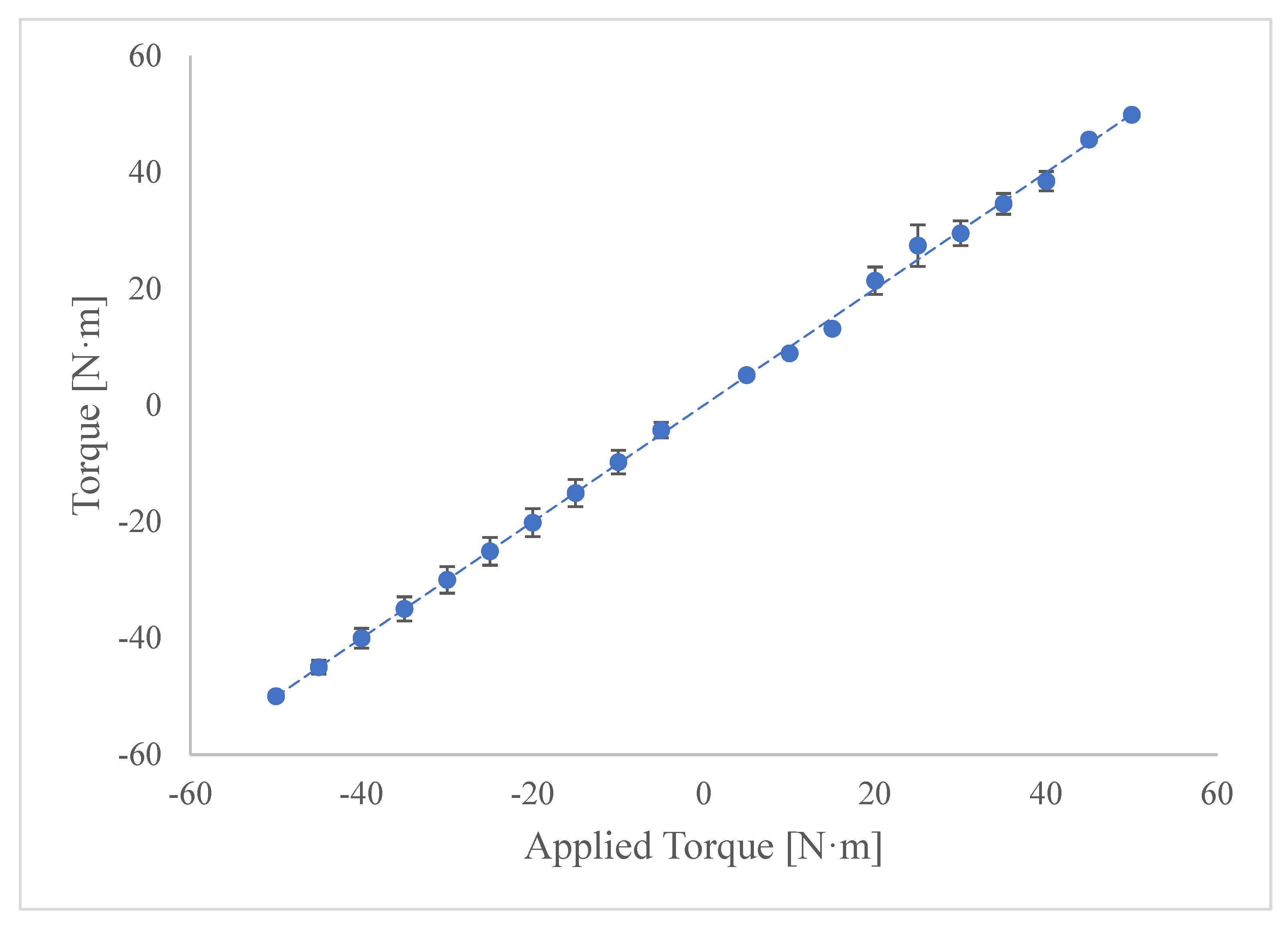
Figure 5 illustrates the correlation between the applied torque (horizontal axis) and the indicated torque measured by the developed sensor system (vertical axis) across the full measurement range, including both clockwise and counterclockwise directions. Each data point represents the mean indicated torque for a specific applied torque value, while the vertical error bars denote the 95% confidence intervals calculated from repeated measurements at each calibration point.
A detailed cost analysis is provided in Table 4.
The cost–accuracy analysis presented in Table 5 shows a markedly nonlinear relationship across the seven benchmarked designs. The Proposed Sensor (ID 1) sets the lowest cost at EUR 27 while achieving ±2.5 N·m (≈5%FS) over ±50 N·m, a level of precision adequate for many service-robot tasks. A modest step up to the Exoskeleton Sensor (ID 2) halves the error to ±2%FS across the same span, yielding the most favorable cost-to-accuracy ratio. The three low-torque variants, 1 N·m, 5 N·m, and 20 N·m Sensors (ID 3–5), remain below EUR 100 yet confine capacity to ≤20 N·m. Their 1–2%FS performance rivals both cheaper and dearer units when normalized to full scale. The Walking Robot Sensor (ID 6) quadruples the ID 2 cost to USD 213, attaining similar ≤2%FS accuracy; its price premium largely reflects environmental sealing and multi-axis capability rather than metrological gain. The Optical Sensor (ID 7) commands the highest price (USD < 250) and delivers the tightest tolerance (±1.5% RMS) but only within ±5 N·m, illustrating diminishing returns beyond the EUR 100 threshold unless exceptional low-torque precision is required.
The qualitative distinctions presented in Table 6 pivot on calibration lineage, enclosure strategy, and wireless autonomy. The Proposed Sensor (ID 1) combines a fifth-order polynomial fit with integrated radio, targeting controlled-environment deployments. ID 2 benchmarks against a commercial transducer, encloses electronics in a 3D printed shell, and offers NRF24L01 telemetry, balancing laboratory reliability with wearable portability. Variants ID 3–5 inherit the same ATI-based calibration but forego both enclosure and wireless capability, maximizing economy for benchtop use. ID 6 couples six-axis load cell calibration with ESP32 Wi-Fi/BLE inside an IP67 case, delivering the most field-ready architecture at higher material and assembly costs. ID 7 relies on optical scale-factor fitting within a rigid CNC-milled aluminum enclosure and omits wireless capability, prioritizing structural stability and optical cleanliness over mobility. Overall, enclosure robustness and communication freedom, rather than calibration sophistication alone, drive the major architectural divergences among contemporary low-cost torque sensors.

5. Discussion

The practical results confirm that an affordable, IoT-enabled torque measurement system can deliver accuracy and reliability comparable to present commercial solutions. The use of strain gauges in a Wheatstone bridge configuration, combined with digital signal amplification, enables precise monitoring of shaft torque in real time. The high R2 values observed in both directions confirm the appropriateness of the polynomial regression model, while the low MAE and standard deviation values demonstrate the system’s accuracy and repeatability. The bidirectional calibration approach distinguishes this work from many previous studies, making the system suitable for applications involving reversible or oscillatory loads. A further practical advantage is installation simplicity: because the strain gauges are surface-mounted, the sensor can be deployed on a drivetrain without any structural modification, eliminating the need to cut the half shaft or fit flange couplers. This capability is particularly important in automotive measurements, where torque sensors must reliably capture rapid changes in direction associated with acceleration, deceleration, and engine braking. In such scenarios, the torque experienced by drivetrain components frequently reverses due to shifting driving conditions, and a sensor calibrated only unidirectionally may yield significant errors or fail to capture the full dynamic behavior.
Potential improvements include miniaturization of the electronics, waterproofing the enclosure for outdoor use, and implementing advanced signal processing algorithms to further reduce noise and enhance dynamic response. Future work will also explore the use of energy harvesting techniques, such as inductive power transfer, to enable continuous operation without battery recharging.
To provide a comprehensive evaluation, Table 7 summarizes the main advantages and limitations of the developed IoT-based torque measurement system. The system’s primary strengths include its low cost, modularity, and open-source design, which collectively enable rapid adaptation to diverse applications and facilitate integration with modern data acquisition workflows. The use of a high-order polynomial calibration model ensures accurate and repeatable measurements for both clockwise and counterclockwise torques, addressing the requirements of reversible and oscillatory load scenarios.
However, the range of limitations that must be addressed differs with the scale and context of the planned deployment. The reliance on battery power restricts operational time between charges, and the current hardware is not yet waterproofed for harsh or outdoor environments. While the open-source approach encourages customization, it may pose challenges for users without technical expertise. Additionally, the calibration process, while robust, is more complex than simple linear methods and requires careful execution to maintain accuracy over time.
Overall, the system offers a compelling balance of affordability, flexibility, and performance, but further improvements—such as enhanced power management, environmental protection, and streamlined calibration procedures—would increase its suitability for broader industrial adoption.
While the system demonstrates short-term accuracy, long-term stability testing is pending. Proposed maintenance includes periodic recalibration (e.g., every 500 h) and onboard temperature monitoring to compensate for thermal drift. Future work will validate these protocols in extended operational scenarios.

6. Conclusions

This study establishes a transparent methodology for bidirectional torque measurement using open-source hardware. The shaft-mounted node, comprising strain gauges, HX711 conditioning, a Wemos D1 Mini ESP8266, and an onboard battery, was calibrated with a certified dynamometric wrench and validated over ±5–50 N·m. Testing confirmed a mean absolute error of 0.559 N·m and precision within ±2.5 N·m (95% confidence) while keeping material cost under EUR 30. Although these results substantiate the feasibility of an accurate, low-cost, and IoT-enabled sensor, the study remains at the proof-of-concept stage, and the novelty of the study resides in integrating wireless transmission, straightforward assembly, and rigorous calibration within a compact platform. The system thereby lowers the barrier to advanced torque monitoring in automotive, industrial, and research applications. Future work will address battery endurance, environmental sealing, and multi-axis capability, enabling extended field trials that will verify long-term reliability, broaden deployment scenarios, and support predictive maintenance architectures aligned with Industry 4.0.

Author Contributions

Conceptualization, V.S. and M.I.; methodology, V.S., M.I. and C.C.S.; software, V.S.; validation, C.C.S., V.S. and R.I.; formal analysis, C.C.S., V.S. and M.I.; investigation, C.C.S. and V.S.; resources, C.C.S. and I.I.; data curation, C.C.S.; writing—original draft preparation, C.C.S., V.S., I.I. and M.I.; writing—review and editing, C.C.S., V.S., I.I., M.I. and R.I.; visualization, C.C.S., V.S. and I.I.; supervision, V.S. and I.I.; project administration, V.S. and I.I. All authors have read and agreed to the published version of the manuscript.

Funding

There was no financial support for the research.

Institutional Review Board Statement

Not applicable.

Informed Consent Statement

Not applicable.

Data Availability Statement

All data underlying the results are available as part of the article; no additional source data are required. Further details or raw data can be provided by the corresponding author upon reasonable request.

Acknowledgments

The authors gratefully acknowledge that this research formed a core component of the first author’s PhD studies at Politehnica University of Timisoara. The constructive feedback and support provided by the reviewers have been instrumental in enhancing the quality and completion of this work.

Conflicts of Interest

The authors declare no conflicts of interest.

Abbreviations

The following abbreviations are used in this manuscript:
IoTInternet of Things
PCBPrinted Circuit Board
Wi-FiWireless Fidelity
N·mNewton Meter
OLSOrdinary Least Squares
MAEMean Absolute Error
SDStandard Deviation
CWClockwise
CCWCounterclockwise
TAREZero-Load Reference Value
RAWLoaded Sensor Value
DVDigital Value (Raw Sensor Output)
R2Coefficient of Determination
ISOInternational Organization for Standardization
AIArtificial Intelligence
BLEBluetooth Low Energy
DVDigital Value
FSFull Scale
RMSARoot Mean Square
ADCAnalog-to-Digital Converter
BF350-3HA-EFoil Strain Gauge Element Employed for Torque Sensing
DC-DCDirect-Current-to-Direct-Current (Power) Converter
DIYDo It Yourself (Low-Cost, Hobbyist Approach)
ESP8266Wi-Fi-Enabled Microcontroller
FTMFine-Time Measurement
HX71124-Bit Load Cell Amplifier and ADC
IDIdentifier (Used in Benchmark Table)
IP67Ingress-Protection Rating: Dust-Tight and Water-Resistant to 1 m for 30 min
Li-PoLithium Polymer (Rechargeable Battery)
OFDMOrthogonal Frequency-Division Multiplexing
RBFRadial Basis Function (Neural Network Kernel)

References

  1. Garshelis, I.J. Torque and Power Measurement. In Mechanical Variables Measurement—Solid, Fluid, and Thermal; CRC Press: Boca Raton, FL, USA, 1999; ISBN 978-1-003-41821-4. [Google Scholar]
  2. Jubair, A.; Mazali, I.I.; Daud, Z.H.C.; CheKob, M.S.; Asus, Z.; Hamid, M.K.A. Torque Meter Calibration for Powertrain Test Bench. AIP Conf. Proc. 2025, 3056, 020007. [Google Scholar] [CrossRef]
  3. Yu, Z.; Zhang, Y.; Yu, W.; Liu, X. Design and calibration of the accurate torque measurement systems of the Precision Robot Reducer Detector. Meas. Control 2023, 56, 989–1003. [Google Scholar] [CrossRef]
  4. Matetić, I.; Štajduhar, I.; Wolf, I.; Ljubic, S. A Review of Data-Driven Approaches and Techniques for Fault Detection and Diagnosis in HVAC Systems. Sensors 2023, 23, 1. [Google Scholar] [CrossRef] [PubMed]
  5. Kiuchi, M.; Nishino, A.; Ogushi, K. Calibration Procedures for Torque Measuring Devices by Using a Reference Type Torque Calibration Machine at NMIJ. Acta IMEKO 2020, 9, 179–183. [Google Scholar] [CrossRef]
  6. Manshin, Y.P.; Yu Manshina, E.; Geue, M. About the Dynamic Error of Strain Gauge Torque Measuring Devices. J. Phys. Conf. Ser. 2021, 2131, 052041. [Google Scholar] [CrossRef]
  7. Smith, J. Practical Problems in Calibration of Torque Tubes. Strain 2008, 13, 148–151. [Google Scholar] [CrossRef]
  8. Nadeau, P.; Garcia, M.R.; Wise, E.; Kelly, J. Automated Continuous Force-Torque Sensor Bias Estimation. arXiv 2024, arXiv:2403.01068. [Google Scholar] [CrossRef]
  9. Xu, F.; Zhu, Y.; Yang, F.; Zhang, X.; Mu, J.; Chen, H.-H. Distributed Modulation Recognition for IoT Devices in Data-Limited Applications. IEEE Internet Things J. 2025, 12, 26740–26752. [Google Scholar] [CrossRef]
  10. Ma, H.; Tao, Y.; Fang, Y.; Chen, P.; Li, Y. Multi-Carrier Initial-Condition-Index-Aided DCSK Scheme: An Efficient Solution for Multipath Fading Channel. IEEE Trans. Veh. Technol. 2025, 1–14. [Google Scholar] [CrossRef]
  11. Passerini, F. Neural Network-Based Calibration of 6D Force-Torque Sensors in Humanoid Robots; Laurea: Politecnico di Torino, Italy, 2024. [Google Scholar]
  12. Lu, T.-F.; Lin, G.C.; He, J.R. Neural-Network-Based 3D Force/Torque Sensor Calibration for Robot Applications. Eng. Appl. Artif. Intell. 1997, 10, 87–97. [Google Scholar] [CrossRef]
  13. Oh, H.S.; Kang, G.; Kim, U.; Seo, J.K.; Choi, H.R. Calibration of 6 Axis Force/Torque Sensor by Using Deep-Learning Method. In Proceedings of the 2017 13th IEEE Conference on Automation Science and Engineering (CASE), Xi’an, China, 20–23 August 2017; pp. 1316–1317. [Google Scholar]
  14. Wang, H.; Zhang, P.; Zhang, H.; Wang, H. New Concepts in the Design of an IoT Electric Torque Wrench Based on a Smart Meter Chip. Eng. Rep. 2024, 6, 12941. [Google Scholar] [CrossRef]
  15. Tang, L.; Hui, X.; Jiang, X.; Xiong, X.; Li, Q.; Guo, H. Tribo-Electrostatic-Based High Precision and Interchangeable Dynamic Torque Sensing by Linear Elastomer Formed Phase Displacement. Nano Energy 2025, 135, 110636. [Google Scholar] [CrossRef]
  16. Tan, R.; Xia, Y.; Han, X.; Huang, L.; Gao, W.; Jia, C.; Yang, P.; Lin, Q.; Ding, S.; Wang, C.; et al. Miniaturized Silicon-Based Capacitive Six-Axis Force/Torque Sensor with Large Range, High Sensitivity, and Low Crosstalk. Microsyst. Nanoeng. 2024, 10, 180. [Google Scholar] [CrossRef] [PubMed]
  17. Othman, W.Z.; Ramli, A.F.; Mamat, N.H.; Abd Aziz, M.R. Cutting Force Measurement Using Strain Gauge and Arduino for Monitoring of Turning Tool Post. J. Phys. Conf. Ser. 2022, 2319, 012018. [Google Scholar] [CrossRef]
  18. Gillot, C.; Picoux, B.; Reynaud, P.; Cardoso Da Silva, D.; Rakotovao-Ravahatra, N.; Feix, N.; Petit, C. Wireless Strain Gauge for Monitoring Bituminous Pavements. Appl. Sci. 2024, 14, 2245. [Google Scholar] [CrossRef]
  19. Turlapati, S.H.; Nguyen, V.P.; Gurnani, J.; Bin Ariffin, M.Z.; Kana, S.; Yee Wong, A.H.; Han, B.S.; Campolo, D. Identification of Intrinsic Friction and Torque Ripple for a Robotic Joint with Integrated Torque Sensors with Application to Wheel-Bearing Characterization. Sensors 2024, 24, 7465. [Google Scholar] [CrossRef] [PubMed]
  20. Shin, J.; Shin, J.; Jung, H.; Won, J.; Auh, E.; Moon, H. On-Site Implementation of External Wrench Measurement via Non-Linear Optimization in Six-Axis Force–Torque Sensor Calibration and Crosstalk Compensation. Appl. Sci. 2025, 15, 1510. [Google Scholar] [CrossRef]
  21. Bosmans, J.; Gallas, S.; Smeets, V.; Kirchner, M.; Geens, L.; Croes, J.; Desmet, W. Experimental Validation of Virtual Torque Sensing for Wind Turbine Gearboxes Based on Strain Measurements. Wind Energy 2025, 28, e2955. [Google Scholar] [CrossRef]
  22. Zhang, H.; Wenske, J.; Reuter, A.; Neshati, M. Proposals for a Practical Calibration Method for Mechanical Torque Measurement on the Wind Turbine Drive Train under Test on a Test Bench. Wind Energy 2020, 23, 1048–1062. [Google Scholar] [CrossRef]
  23. Fidelus, J.D.; Puchalski, J.; Trych-Wildner, A.; Urbański, M.K.; Weidinger, P. Estimation of Uncertainty for the Torque Transducer in MNm Range—Classical Approach and Fuzzy Sets. Energies 2023, 16, 6064. [Google Scholar] [CrossRef]
  24. Voronin, S.S.; Loginov, B.M.; Gasiyarova, O.A.; Evdokimov, S.A.; Karandaev, A.S.; Khramshin, V.R. Telemetry System to Monitor Elastic Torque on Rolling Stand Spindles. J. Manuf. Mater. Process. 2024, 8, 85. [Google Scholar] [CrossRef]
  25. Yu, Z.; Yu, W. Shafting Misalignment Malfunction Quantitative Diagnosis Based on Speed Signal SVD-HT and CSF-PPSO-ESN Method. Comput. Intell. Neurosci. 2022, 2022, 7016597. [Google Scholar] [CrossRef] [PubMed]
  26. Chahmi, A. Study and Realization of a Torque Measurement Sensor Based on Strain Gauges Dedicated to Bending and Torsion. In Proceedings of the 2022 2nd International Conference on Advanced Electrical Engineering (ICAEE), Constantine, Algeria, 29–31 October 2022; pp. 1–5. [Google Scholar]
  27. Popelka, J.; Mikulanin, L.; Scholz, C. Construction of the Measuring Device for Analyzing the Internal Combustion Engine Torque. Appl. Mech. Mater. 2015, 799–800, 947–951. [Google Scholar] [CrossRef]
  28. Lopot, F.; Dub, M.; Flek, J.; Hadraba, D.; Havlíček, M.; Kučera, L.; Štoček, O.; Veselý, T.; Janáček, J. Gearbox Mechanical Efficiency Determination by Strain Gauges Direct Application. Appl. Sci. 2021, 11, 11150. [Google Scholar] [CrossRef]
  29. Ehsani, A.; Khomami, N.A.; Ghaneie, M.; Masouleh, M.T. Design and Fabrication of an Optimized Six-Axis Force-Torque Sensor. In Proceedings of the 2023 11th RSI International Conference on Robotics and Mechatronics (ICRoM), Tehran, Iran, 19 December 2023; pp. 598–605. [Google Scholar]
  30. Suciu, C.C.; Stoica, V.; Ilie, M.; Ionel, I. A Novel Approach to Real-Time Torque Measurement through IoT-Integrated Strain Gauges and Neural Network Calibration. In Proceedings of the CIE/C2I 2025: International Conference on Industrial Engineering and Computer Integrated Manufacturing, Timișoara, Romania, 12–14 June 2025. presented, not yet published. [Google Scholar]
  31. Hemeda, S.G.; Aboukarima, A.M.; Minyawi, M. Developing a logging unit for measuring and recording power data using arduino board. Misr J. Agric. Eng. 2017, 34, 2053–2072. [Google Scholar] [CrossRef]
  32. Tarakçi, S.; Aldemir, O.; Solmaz, T.; Işik, E. External Torque Sensor Design Providing Wireless and Real-Time Data Customized for Drivetrain. Int. J. Automot. Eng. Technol. 2022, 11, 18–27. [Google Scholar] [CrossRef]
  33. Szybicki, D.; Obal, P.; Kurc, K.; Gierlak, P. Programming of Industrial Robots Using a Laser Tracker. Sensors 2022, 22, 6464. [Google Scholar] [CrossRef] [PubMed]
  34. Kalcher, R.; Ellermann, K.; Kelz, G. Load Torque Estimation for an Automotive Electric Rear Axle Drive by Means of Virtual Sensing Using Kalman Filtering. Int. J. Veh. Perform. 2021, 8, 1–30. [Google Scholar] [CrossRef]
  35. Xia, K.; Lou, Y.; Yuan, Q.; Zhu, B.; Li, R.; Du, Y. Optoelectronic Torque Measurement System Based on SAPSO-RBF Algorithm. Sensors 2024, 24, 1576. [Google Scholar] [CrossRef] [PubMed]
  36. Usui, T.; Ishizuka, H.; Kawasetsu, T.; Hosoda, K.; Ikeda, S.; Oshiro, O. Soft Capacitive Tactile Sensor Using Displacement of Air–Water Interface. Sens. Actuators A Phys. 2021, 332, 113133. [Google Scholar] [CrossRef]
  37. Kim, J. Real-Time Torque Estimation of Automotive Powertrain with Dual-Clutch Transmissions. IEEE Trans. Control Syst. Technol. 2022, 30, 2269–2284. [Google Scholar] [CrossRef]
  38. Kružić, S.; Musić, J.; Papić, V.; Kamnik, R. Strain Gauge Neural Network-Based Estimation as an Alternative for Force and Torque Sensor Measurements in Robot Manipulators. Appl. Sci. 2023, 13, 10217. [Google Scholar] [CrossRef]
  39. Kraus, A.; Stiegelmeyr, A. Dynamic Brake Test Stand; SAE International: Warrendale, PA, USA, 2021. [Google Scholar]
  40. Aguirre Rodriguez, J.; Castano, J.; Saeed, A. Modular Torque Wrench Extension with Heads-up Display. In Engineering, Integration, and Alliances for A Sustainable Development. Hemispheric Cooperation for Competitiveness and Prosperity on A Knowledge-Based Economy, Proceedings of the 18th LACCEI International Multi-Conference for Engineering, Education, and Technology, Virtual, 27–31 July 2020; Latin American and Caribbean Consortium of Engineering Institutions: San Jose, CA, USA, 2020. [Google Scholar]
  41. Hameed, M.; Saleh, M. Study the Opportunity of Using Arduino Controller for Practical Stress Measurement Induced in Mechanical Loaded Members. J. Mech. Eng. Autom. Control Syst. 2025, 6, 14–26. [Google Scholar] [CrossRef]
  42. Suryawanshi, R. AI in Sensor Calibration. IJRASET 2025, 13, 1197–1200. [Google Scholar] [CrossRef]
  43. Karki, D.; Dura, H.B.; Poudel, L. Design, Construction and Performance Analysis of Dynamic Torque Transducer. J. Innov. Eng. Educ. 2023, 6, 118–123. [Google Scholar] [CrossRef]
  44. ISO 376:2011. Available online: https://www.iso.org/standard/44661.html (accessed on 25 June 2025).
  45. Linear Regression: Estimation and Distribution Theory. In Linear Regression Analysis; John Wiley & Sons, Ltd.: Hoboken, NJ, USA, 2003; pp. 35–95. ISBN 978-0-471-72219-9.
  46. Nagelkerke, N.J.D. A Note on a General Definition of the Coefficient of Determination. Biometrika 1991, 78, 691–692. [Google Scholar] [CrossRef]
  47. Taylor, M.H.; Losch, M.; Wenzel, M.; Schröter, J. On the Sensitivity of Field Reconstruction and Prediction Using Empirical Orthogonal Functions Derived from Gappy Data. J. Clim. 2013, 26, 9194–9205. [Google Scholar] [CrossRef]
  48. Taylor, B.N. Guidelines for Evaluating and Expressing the Uncertainty of NIST Measurement Results; National Bureau of Standards: Gaithersburg, MD, USA, 1994. [Google Scholar]
  49. Preethichandra, D.M.G.; Piyathilaka, L.; Sul, J.-H.; Izhar, U.; Samarasinghe, R.; Arachchige, S.D.; de Silva, L.C. Passive and Active Exoskeleton Solutions: Sensors, Actuators, Applications, and Recent Trends. Sensors 2024, 24, 7095. [Google Scholar] [CrossRef] [PubMed]
  50. Ubeda, R.P.; Gutiérrez Rubert, S.C.; Zotovic Stanisic, R.; Perles Ivars, Á. Design and Manufacturing of an Ultra-Low-Cost Custom Torque Sensor for Robotics. Sensors 2018, 18, 1786. [Google Scholar] [CrossRef] [PubMed]
  51. Billeschou, P.; Albertsen, C.; Larsen, J.C.; Manoonpong, P. A Low-Cost, Compact, Sealed, Three-Axis Force/Torque Sensor for Walking Robots. IEEE Sens. J. 2021, 21, 8916–8926. [Google Scholar] [CrossRef]
  52. Kim, H.-B.; Choi, K.-H.; Kim, K.-S. A Compact Optical Six-Axis Force/Torque Sensor for Legged Robots Using a Polymorphic Calibration Method. arXiv 2023, arXiv:2309.04720. [Google Scholar]
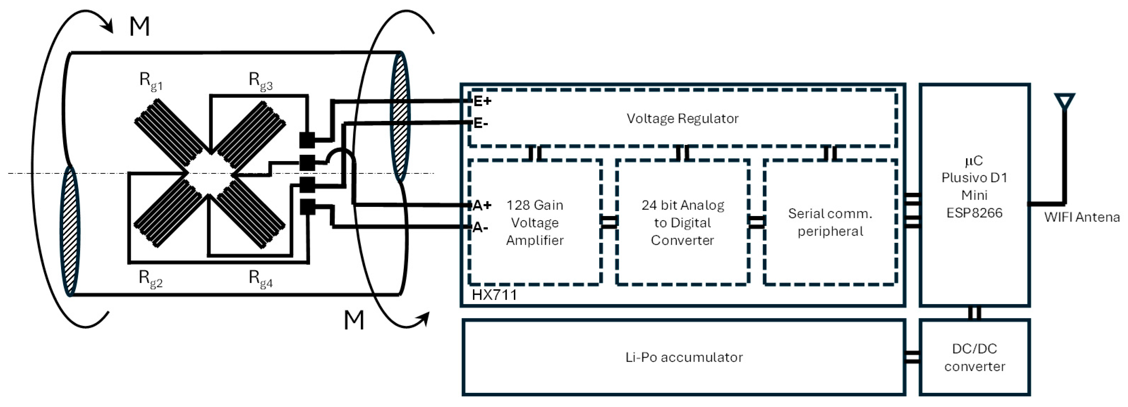
Figure 1. Schematic of the strain gauge Wheatstone bridge configuration and signal flow.
Applsci 15 08158 g001
Figure 2. The schematic diagram of the hardware configuration. Each component is labeled for clarity.
Applsci 15 08158 g002
Figure 3. Experimental setup with torque wrench: 1—clamped end; 2—torque sensor; 3—half shaft; 4—torque wrench.
Applsci 15 08158 g003
Figure 4. Calibration curve showing applied torque vs. indicated digital value using fifthorder polynomial regression.
Applsci 15 08158 g004
Figure 5. Calibration curve showing applied torque vs. indicated torque using fifth-order polynomial regression.
Applsci 15 08158 g005
Table 1. Correlation between applied torque and sensor averaged digital value for clockwise and counterclockwise directions.
Applied Torque
[N·m]
Averaged Digital Value
(Clockwise)
Averaged Digital Value
(Counterclockwise)
5416,014.40526,014.00
10379,772.40607,232.00
15342,533.00702,498.00
20279,097.20813,371.00
25238,616.20941,406.00
30225,340.201,088,161.00
35195,485.801,255,192.00
40174,029.801,444,057.00
45137,405.801,656,311.00
50117,235.801,893,513.00
Table 2. Correlation between applied torque and indicated torque.
Applied Torque
[N·m]
Indicated Torque
[N·m]
MAE
[N·m]
5049.886584950.113415
4545.642360650.642361
4038.483844611.516155
3534.598444550.401555
3029.544963050.455037
2527.422662052.422662
2021.393669421.393669
1513.156425511.843574
108.9267822811.073218
55.1886838550.188684
−5−4.2447575470.755242
−10−9.7503585110.249641
−15−15.064033540.064034
−20−20.149735590.149736
−25−25.070850060.070850
−30−29.963741040.036259
−35−34.948369280.051631
−40−40.006953760.006954
−45−44.969333590.030666
−50−49.96739410.032606
Table 3. Statistical analysis of calibration results.
Applied Torque
[N·m]
Indicated Torque
[N·m]
Standard Deviation
[N·m]
2 × Standard Deviation
[N·m]
5049.886584950.1125840120.225168025
4545.642360650.1555287370.311057475
4038.483844610.8328476451.66569529
3534.598444550.8891280711.778256143
3029.544963051.0615657222.123131444
2527.422662051.7829403053.565880609
2021.393669421.1748732532.349746505
1513.156425510.1339334790.267866959
108.9267822810.1662902300.332580460
55.1886838550.2981115770.596223154
−5−4.2447575470.6741215611.348243122
−10−9.7503585111.0070546512.014109302
−15−15.064033541.1705359442.341071889
−20−20.149735591.2153382512.430676502
−25−25.070850061.1966574462.393314893
−30−29.963741041.1439101612.287820322
−35−34.948369281.0373765982.074753196
−40−40.006953760.8457188741.691437749
−45−44.969333590.5839606871.167921373
−50−49.96739410.3286662410.657332481
Table 4. Cost breakdown of the IoT-based torque measurement system.
ComponentSpecificationCost [EUR]Date of Purchase
Strain Gauge (×4)BF350-3HA-E8May 2025
AmplifierHX7114May 2025
MicrocontrollerWemos D1 Mini ESP82667May 2025
Battery400 mAh Li-Po5May 2025
DC-DC Converter3.3/5 V3May 2025
Total 27May 2025
Table 5. Quantitative benchmark for multiple torque measurement systems.
IDSystemPrice Quoted in PaperMeasurement Range [N·m]AccuracyBidirectional
1Proposed SystemEUR 27±50±2.5 N·mYes
2Exoskeleton Sensor [49]USD 50±50±2 N·mYes
31 N·m Sensor [50]EUR < 10011.92% FSNot stated
45 N·m Sensor [50]EUR < 10051.27% FSNot stated
520 N·m Sensor [50]EUR < 100201.27% FSNot Stated
6Walking Robot Sensor [51]USD 213±15<2% FSYes
7Optical Sensor [52]USD < 250±5±1.5% FSYes
Table 6. Qualitative features of multiple torque measurement systems.
IDSystemCalibration MethodWirelessEnclosureDistinct Strengths
1Proposed SystemFifth-order polynomialYesNoYes
2Exoskeleton SensorCommercial torque-transducer comparisonYesYesTelemetry
31 N·m SensorBenchmarked to ATI Delta SI-330-30NoNoEconomy for benchtop use
45 N·m SensorBenchmarked to ATI Delta SI-330-30NoNoEconomy for benchtop use
520 N·m SensorBenchmarked to ATI Delta SI-330-30NoNoEconomy for benchtop use
6Walking Robot SensorSix-axis load cell referenceYesYesIP67 enclosure
7Optical SensorOptical scale-factor fitNoYesCNC-milled aluminum enclosure
Table 7. Critical analysis of the proposed IoT-based torque measurement system.
AspectAdvantagesDisadvantages/Limitations
CostSignificantly lower than commercial systems; affordable componentsMay lack some features of high-end commercial solutions
ModularityEasily adapted to various shaft sizes and applicationsCustomization requires mechanical adaptation and recalibration
CalibrationBidirectional, high-order polynomial fit enables accurate reversible/oscillatory load measurementCalibration process is more complex than simple linear fit
Open-Source Design
Maintenance
Firmware and interface are open, enabling community-driven improvements and integrationRequires user expertise for modification or troubleshooting
Accuracy and RepeatabilityHigh R2, low MAE and SD; comparable to commercial systemsPerformance may degrade if installation quality is poor
ScalabilityEasily replicated for multi-point or distributed sensingNetwork congestion possible with many devices
MaintenanceSimple, low-cost replacement of componentsLong-term stability and drift require periodic recalibration
Disclaimer/Publisher’s Note: The statements, opinions and data contained in all publications are solely those of the individual author(s) and contributor(s) and not of MDPI and/or the editor(s). MDPI and/or the editor(s) disclaim responsibility for any injury to people or property resulting from any ideas, methods, instructions or products referred to in the content.