1. Introduction
In response to the global climate crisis and the need to combat global warming, the European Union officially signed the Green Deal Agreement in 2020. This accord aims to achieve a 55% reduction in carbon dioxide (CO
2) emissions by 2030 compared to 1990 levels [
1], with the ultimate goal of reaching net-zero emissions by 2040. Consequently, significant initiatives have been undertaken across the energy and automotive sectors to meet these ambitious targets.
Within the European Union, the transportation sector accounts for approximately 32% of total CO
2 emissions, with road transportation contributing 73% of this share. Heavy-duty vehicles alone produce 6% of global CO
2 emissions, accounting for 26% of emissions from road transport [
2]. In response, manufacturers are increasingly shifting towards battery-electric propulsion for light-duty and passenger vehicles. Although regional delivery trucks with battery-electric capabilities have emerged, the practical implementation of battery-electric systems for long-distance heavy-duty trucks remains challenging due to limited range and extended charging times. Hydrogen fuel is thus anticipated to provide a viable solution for heavy-duty transportation applications [
3].
Two primary hydrogen powertrain configurations have been proposed. The first involves the use of fuel cells to power electric motors and batteries. However, fuel cells are sensitive to dusty environments, require high-purity hydrogen, and demand precise thermal management. Moreover, their reliance on rare materials [
4], susceptibility to efficiency loss under high loads, limited operational lifespan, and high costs [
5] present significant drawbacks.
Conversely, hydrogen-fueled internal combustion engines (H2-ICEs) offer a more economical, durable, and sustainable alternative. Unlike fuel cells, H2-ICEs can operate effectively without requiring high-purity hydrogen. Nevertheless, due to the high diffusivity of gaseous hydrogen, ensuring a homogeneous air–fuel mixture and maintaining stable combustion within the cylinder remains a critical challenge. Effective management of hydrogen combustion is essential to avoid knocking phenomena and preserve engine performance, particularly for heavy-duty engines requiring substantial injection quantities.
In this study, injector hole design parameters were optimized to improve air–fuel mixture homogeneity and combustion stability through hydrogen gas injection into the cylinder. Given the importance of model accuracy in achieving reliable optimization results, the CFD model employed in this work was first validated against experimental data obtained from a single-cylinder research engine with available Particle Image Velocimetry (PIV) measurements [
6].
Building upon this validated framework, the central research question of this study is whether optimizing the injector hole design, specifically the number of holes and their injection angles, can improve combustion stability, enhance engine performance, and reduce NOx emissions in a lean hydrogen-fueled heavy-duty engine. The main hypothesis is that adjusting these parameters leads to better in-cylinder air–fuel mixing, which increases indicated mean effective pressure (IMEP), while reducing the likelihood of misfire, knock, and excessive NOx formation, without the need for high injection pressures or complex fuel systems.
While several studies have addressed hydrogen injector design using either experimental or CFD methods, most have focused on fixed geometries or did not include experimental flow field validation. Moreover, there remains limited work combining CFD-validated flow structures with surrogate-assisted optimization techniques under lean hydrogen conditions.
To address this gap, the present study uses a CFD model that was previously validated through Particle Image Velocimetry (PIV) comparisons. This validated model is then integrated into a Kriging-based multi-objective genetic algorithm framework to systematically optimize the injector hole count and injection angle in a low-pressure direct injection (LPDI) configuration. The goal is to improve engine performance and reduce NOx emissions under lean hydrogen combustion conditions.
Several previous studies have contributed valuable insights into hydrogen-fueled internal combustion engine development. For example, Sandia National Laboratories developed a single-cylinder hydrogen research engine in which nitrogen gas was injected to examine mixture formation without combustion. This study generated in-cylinder pressure and velocity vector data across crank angles using PIV measurements [
6], and forms the experimental basis for the validation carried out in the present work.
Qu and Fang et al. [
7] focused on optimizing the injection system for a medium-speed, four-stroke hydrogen engine. Their research emphasized that turbulence intensity and injection penetration distance are critical for achieving homogeneous mixtures, particularly in large-bore DI hydrogen engines. Through systematic optimization, they proposed injection parameters 300 [bar] injection pressure, 10 [°CA] duration, and a 2.8 [mm] injector nozzle diameter that led to a significant reduction in NO
x emissions (over 80%) while maintaining engine power above 80% of the original diesel engine benchmark.
In the context of CFD validation methods, Blane Scott et al. [
8] introduced several comparison metrics (e.g., weighted relevance index, magnitude index) to assess flow field accuracy between CFD predictions and PIV measurements. Their study demonstrated that early detection of non-uniformity in mixture distribution can significantly improve combustion modeling accuracy. However, slight overpredictions in intake jet behavior were observed during valve closure events.
Tang-Wei Kuo et al. [
9] explored 1D–3D CFD coupling approaches using large eddy simulation (LES) for engine flow predictions. Their study compared 56 engine cycles between simulations and experiments, ultimately recommending a 1 mm mesh size for ports and runners to improve flow mixture representation.
Further research by Manzoor et al. [
10] focused on simulating knock events in internal combustion engines. Their findings highlighted the role of temperature stratification and hotspot formation near the exhaust valve region in promoting knock, resulting in pressure oscillations exceeding 100 kPa following auto-ignition events.
Experimental studies by Furuhama et al. [
11] demonstrated that hydrogen–air spark ignition engines can operate efficiently under low-load conditions while controlling NO
x emissions. However, they also reported the emergence of abnormal combustion phenomena as the mixture approached stoichiometric conditions or full-load operation.
Over the past decade, employing genetic algorithm techniques for the multi-objective optimization of combustion chamber design and engine parameters has been quite popular [
12,
13]. In a recent study, Alattwani et al. [
12] implemented a comprehensive multi-objective optimization methodology by coupling the NSGA-II algorithm with CONVERGE CFD to evaluate the effects of operational parameters on a methane/diesel RCCI engine. Their results demonstrated that optimizing parameters such as injection timing, fuel mass, and engine speed led to a 27.8% reduction in ISFC and up to 99% lower CO emissions compared to conventional diesel combustion. The study also highlighted the existence of clear trade-offs between NO
x and unburned hydrocarbon emissions across the Pareto-optimal solutions.
Şener et al. [
13] conducted a shape optimization study to enhance combustion efficiency and reduce emissions in a compression-ignition engine. Using CFD-based simulations in CONVERGE and a multi-objective genetic algorithm in CAESES, they optimized key piston bowl and injection parameters. A total of 104 chamber geometries and 23 injection strategies were evaluated to meet performance and emission targets. The optimized design significantly lowered NO
x and soot emissions while maintaining engine power.
Li and Gao [
14] investigated the effects of hydrogen injection strategies on engine performance and emissions. Their work concluded that optimizing parameters such as injection timing, pressure, and dual injection strategies can enhance mixture uniformity and tumble strength, ultimately reducing the mass fraction of fuel burned in regions exceeding 2500 K values and NO
x emissions.
Breda et al. [
15] performed a computational study to improve fuel–air mixing and combustion efficiency in a high-speed direct-injection hydrogen engine. They evaluated eight injector cap geometries under engine-like conditions (6000 rpm, stoichiometric mixture, IMEP > 25 bar) using 3D CFD simulations. Designs aligned with the cylinder axis or tumble vortex enhanced mixture uniformity by up to 5%, while upstream-directed jets reduced it by 15%. The best design increased output by 5% and reduced combustion duration by 30%, demonstrating the impact of optimized cap geometry on in-cylinder flow and combustion.
Although Breda et al. [
15] achieved performance improvements through their injector cap optimization, their study was conducted with a relatively richer mixture (approximately lambda 1.3) and did not account for emission formation. In contrast, the present work was carried out under leaner combustion conditions with a global lambda of 2.1, which inherently favors lower NO
x emissions. Due to this fundamental difference in operating regimes and evaluation focus, a direct one-to-one comparison between the two studies may not fully capture the emission-oriented contributions of the current methodology.
Gerke [
16], supported by BMW Group Research and Technology, conducted three-dimensional numerical simulations to investigate mixture formation and combustion processes in direct-injection hydrogen engines. His findings highlighted the importance of accurate turbulence and combustion modeling and provided burning velocity data for hydrogen–air mixtures under different injection strategies (homogeneous, stratified, and multi-injection modes).
Agarwal et al. [
17] investigated the effects of fuel inlet configuration on fluid flow and thrust performance in aero-engine combustion chambers. Using CFD simulations performed in ANSYS CFX with geometries modeled in Creo 6.0, they compared single and double fuel inlet designs. The study found that the double inlet configuration significantly increased outlet pressure and thrust. These results suggest improved combustion efficiency and potential gains in turbine performance.
Chen et al. [
18] conducted a CFD-based investigation to compare the combustion and flow characteristics of aero-engine chambers with single and double fuel inlets. Their results indicated that the double-inlet configuration enhanced fuel–air mixing, leading to a 49% increase in outlet pressure and a 48% improvement in thrust compared to the single-inlet design. These findings suggest that fuel inlet configuration plays a critical role in optimizing combustion chamber performance. Building upon this insight, further studies are needed to explore detailed flow structures, flame development, and the associated thermal effects under various operating conditions.
In contrast to this case-specific numerical investigation, our study incorporates experimental validation through Particle Image Velocimetry (PIV) measurements to ensure the reliability of the CFD model under realistic flow conditions. Moreover, rather than evaluating a fixed set of injector configurations, a mathematical design framework was developed by coupling the validated model with a Kriging-based Multi-Objective Genetic Algorithm (MOGA). This approach enabled the systematic optimization of injector parameters with respect to both performance and emissions, offering a more generalized and robust methodology for hydrogen injector design beyond geometry-specific assessments.
2. Methodology
Developed injectors can inject hydrogen into cylinders at pressures ranging from 10 to 300 bar, with various designs featuring different hole counts and injection angles. Rather than designing a completely novel injector, this study aims to optimize the cap configuration of a standard hydrogen injector platform commonly used in heavy-duty applications. This allows the results to be directly applicable to existing engine architectures and manufacturing constraints while still achieving performance and emission improvements through geometric tuning.
For this purpose, CFD combustion simulations were carried out to systematically evaluate and optimize various injector blow cap configurations, with the goal of enhancing gross thermal efficiency and indicated cylinder power while preventing abnormal combustion behavior, such as knocking events.
Ricardo’s hydrogen-fueled research engine [
19] specifications showed in
Table 1 were adopted as the reference model due to their industrial relevance, public data availability, and their geometric similarity to current heavy-duty hydrogen engine concepts. This engine was developed specifically for long-haul truck applications, making it well-suited for assessing injector optimization strategies under realistic conditions.
Hydrogen injection was modeled to occur between −140 °CA and −70 °CA. The baseline configuration employed a low-pressure direct injection (LPDI) system with an injection pressure of 25 bar. This configuration was preferred due to the use of a lower-pressure fuel pump and its safer operational characteristics for heavy-duty engine conditions.
LPDI systems exhibit sensitivity to injector design parameters such as hole count and injection angle. At low injection velocities, mixture formation is more readily simulated and validated through numerical methods [
18]. Based on these considerations, an LPDI-based setup was considered appropriate for the optimization study. Although similar optimization strategies could also be applied to HPDI systems and may yield valuable design insights, this study focused solely on LPDI configuration due to its applicability and implementation within the selected engine concept.
The optimization focused on two primary parameters to achieve an appropriate air–fuel mixture and optimal engine performance while minimizing NOx emissions: injector hole count and injection angle. The hole count was varied between three and five, and the injection angle ranged from 15° to 33°. These parameter ranges were determined based on the geometric feasibility to accommodate the hole configurations on the injector tip.
Converge CFD v3.2 software was employed to carry out the CFD combustion cases, and CAESES v4.4.2 software was utilized for optimization to maximize indicated brake mean effective pressure and minimize NOx emissions. Before the optimization study, a full-cycle CFD combustion simulation was conducted over two cycles (1440 CA Total Duration) without a blow cap injection hole design to establish the initial conditions for optimization.
The optimization study began at −145 CA before TDC and concluded at +50 CA after the top dead center to reduce computation time and costs. MAP-type CFD initialization was applied to the simulation, mapping in-cylinder pressure, temperature, and species distribution directly into the computational domain with 2.6% H2O EGR. As a result, the optimization study was initiated in the same manner as the full-cycle simulation, where the cylinder domain was pre-charged with combustion residuals.
The EGR level used in this setup was calculated from the baseline CFD analysis and fixed at 2.6% throughout the optimization process. This approach ensured consistency in evaluating the effects of injection parameters. A study by Yao et al. [
20] on a 2.0 L heavy-duty hydrogen engine demonstrated that EGR levels between 2% and 4% effectively reduced NO
x emissions, particularly under high-load conditions. In that study, NO
x formation was computed using the extended Zeldovich mechanism, and the predicted trends were found to be in good agreement with experimental measurements. These findings support the reliability of the mechanism for hydrogen combustion modeling. Fixing the EGR level in the current work allowed for a focused assessment of injector geometry on NO
x formation, independent of EGR variation.
The intake port pressure was set to 2.65 bar to simulate boosted operation, while a global lambda of 2.1 ensured lean combustion conditions. Hydrogen was directly injected at 25 [Bar], providing adequate momentum for effective in-cylinder mixing under the low-pressure direct-injection (LPDI) concept.
Although the combustion analysis in the present study does not rely on experimental direct in-cylinder pressure validation, the CFD model was verified using Particle Image Velocimetry (PIV) results. To ensure consistency and comparability, the same SAGE combustion model and RNG k-ε turbulence model were used, in line with the methodology employed by Li et al. [
14], who conducted a detailed numerical investigation on knock formation in hydrogen direct injection engines. Furthermore, similar mesh metrics were applied to construct a reliable and representative combustion framework. All simulations successfully achieved the convergence criteria, reinforcing the robustness of the numerical analysis. In addition to this methodological alignment, the present study included base-case comparisons and a systematic evaluation of performance and emission trends across various design cases. These comparisons enabled a comprehensive assessment of the model’s behavior, thereby supporting the validity and reliability of the overall combustion modeling framework.
A Kriging-based multi-objective genetic algorithm [
21] was employed for optimization, targeting the maximization of brake mean effective pressure while minimizing NO
x emissions. Sixteen sampling design iterations were automatically generated by the optimization algorithm utilizing the Latin Hypercube sampling method [
22], while six optimization design iterations were defined as the input for the optimization process. Twenty-two design iterations were successfully completed using a full coupling of CFD combustion simulations and optimization software. The computation domain was automatically updated by regenerating the CFD surface domain for each design iteration. Java code was developed to calculate the IMEP value for each design iteration in the optimization software, thus allowing automatic engine power calculation for each design iteration based on the IMEP value. On the other hand, the total NO
x emissions for the cylinder at +50 CA were computed for each design iteration, factoring in the NO
x expelled from the exhaust port and the full-cycle validation case results.
However, before the optimization study, ensuring that the CFD model mesh settings could accurately capture high-speed (Mach > 1) flow mixture modeling was essential. In this context, the CFD model was validated through a verification study that included PIV test results from Sandia National Laboratory. The CFD analysis results, utilizing base mesh distance dimensions of 3 mm, 4 mm, and 5 mm, were evaluated for accuracy using GSI and LSI metrics developed by Lee using a MATLAB comparison code. The CFD model was validated against the GSI and LSI metrics by applying the comparison code and interpolating from the CFD environment to the PIV measurement plane. The results were assessed for optimal solution speed and accuracy. Subsequently, an optimization study was conducted using the selected mesh settings.
3. PIV Measurement of Research Engine and Specification
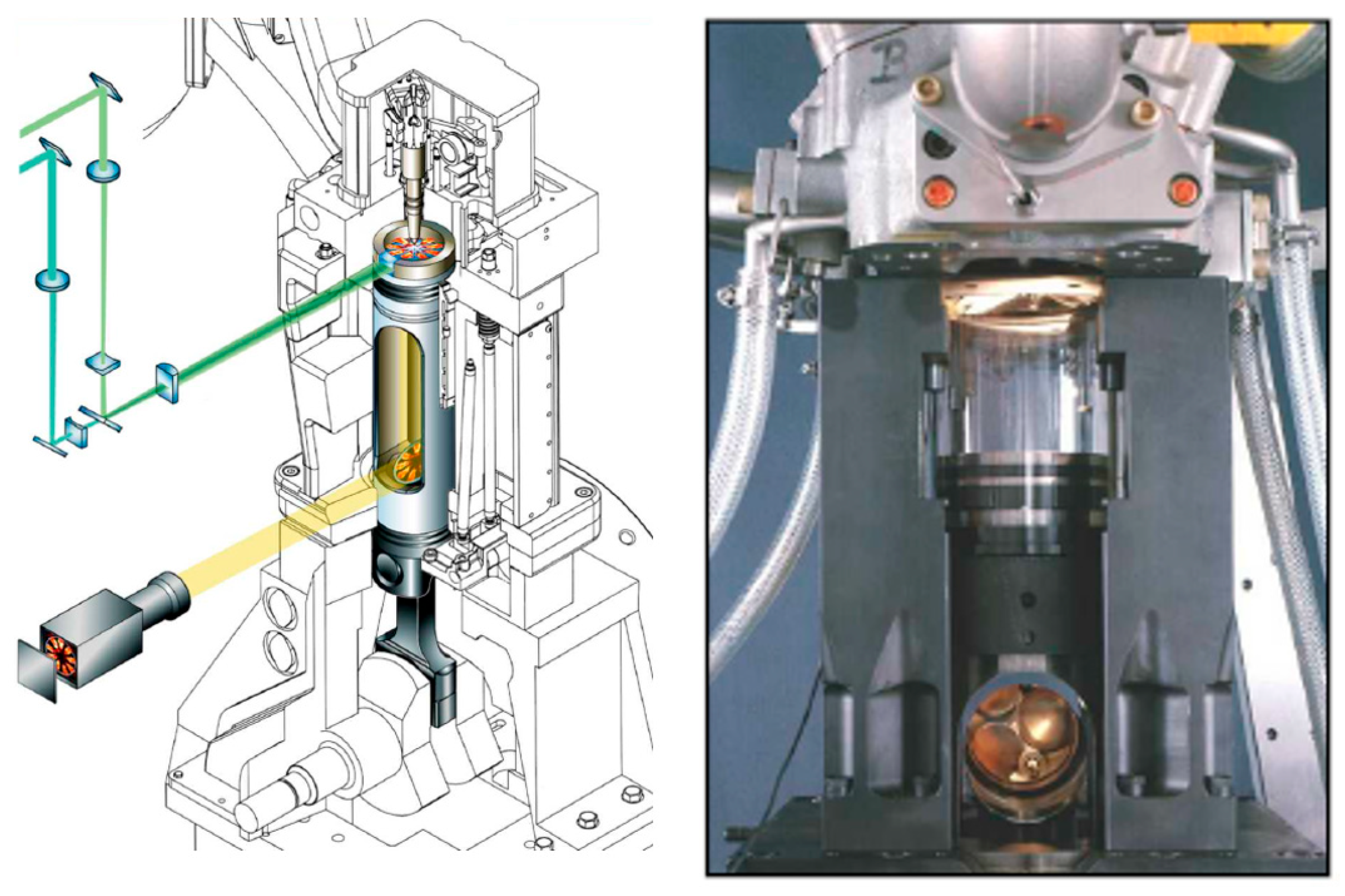
Sandia National Laboratories conducted a PIV measurement campaign [
6] to evaluate the flow distribution of a nitrogen and hydrogen gas mixture within an internal combustion engine. The test details and engine specifications are summarized in
Table 2 and illustrated in
Figure 1. The experimental data are publicly available and have been published through the Engine Combustion Network (ECN), facilitating CFD model validation studies.
During testing, nitrogen gas was supplied to the engine intake at a pressure of 100 kPa and a temperature of 36 °C, while the outlet pressure was maintained at 95 kPa. These intake and outlet pressure profiles were shared as time-dependent data on Sandia National Laboratories’ public website.
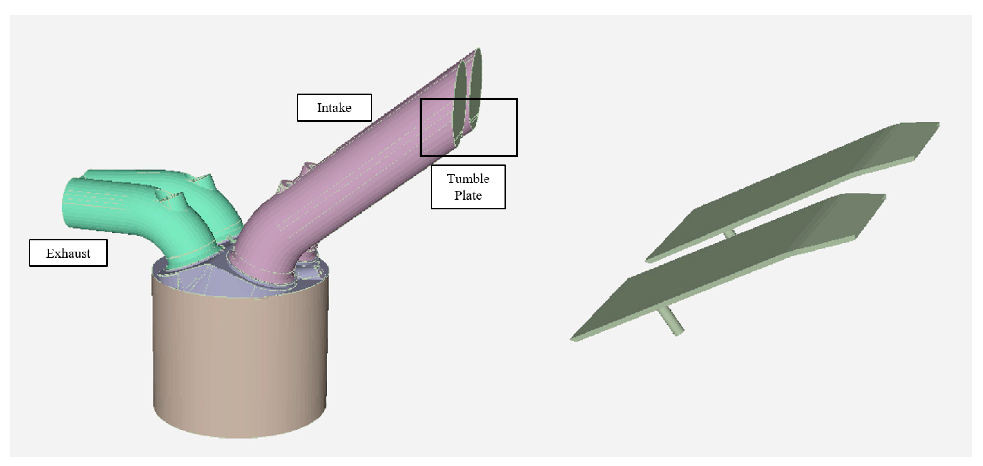
The experimental data were obtained under two configurations: with and without the tumble adapter, which initiates the tumble motion of the mixture within the cylinder prior to injection, as shown in
Figure 2. The PIV measurement plane was positioned across both the cylinder centerline and the lateral axis, as also depicted in
Figure 2.
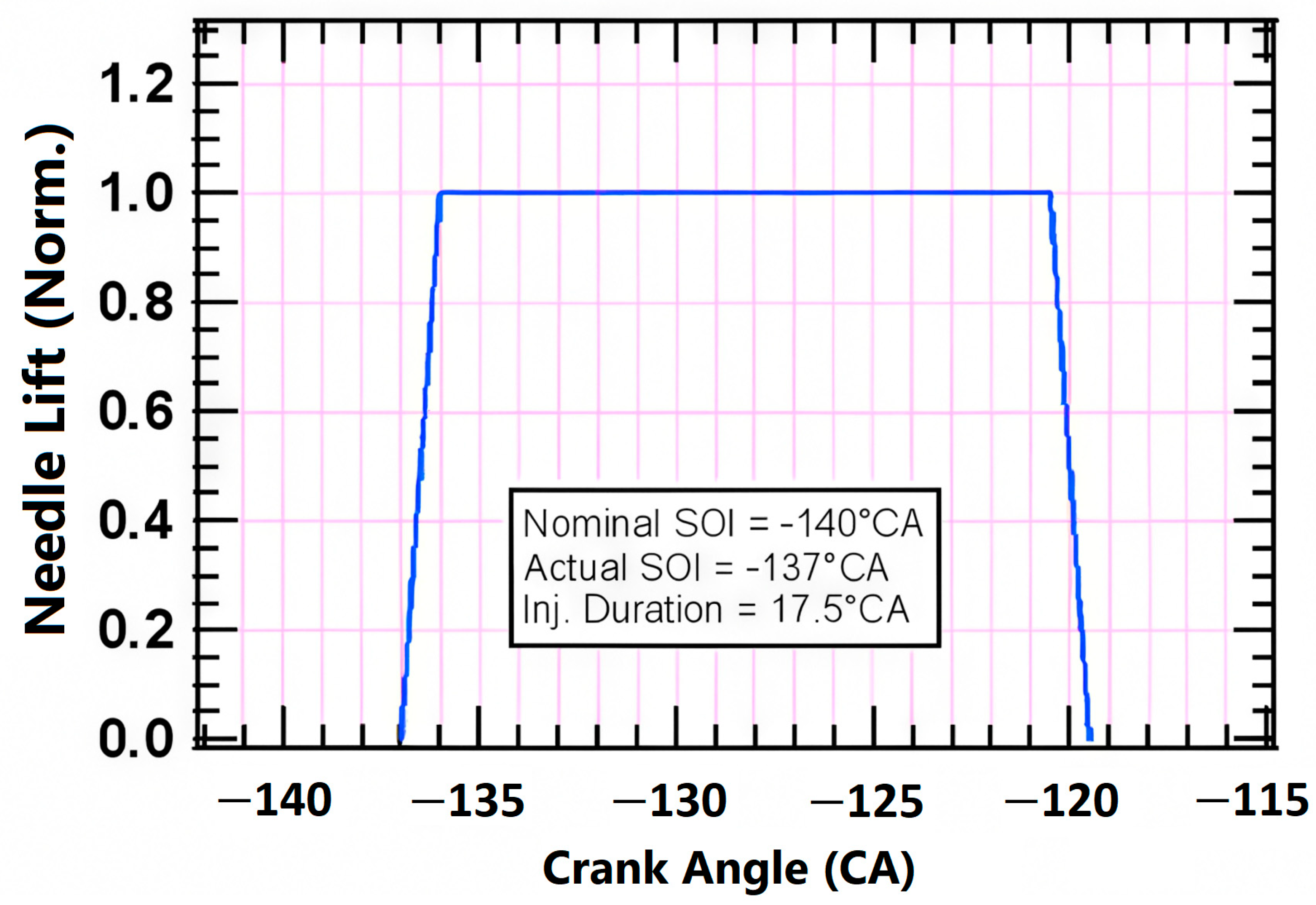
The velocity field results were computed as ensemble averages over 200 cycles based on spatial coordinates, specific crank angle positions, and velocity vector components. Furthermore,
Figure 3 presents the time-dependent lift profile of the injection needle for the test engine.
The test conditions included a hydrogen gas injection quantity of approximately 4.36474 [mg/per cycle], ensuring consistent mixture formation for the PIV validation.
4. Numerical Model
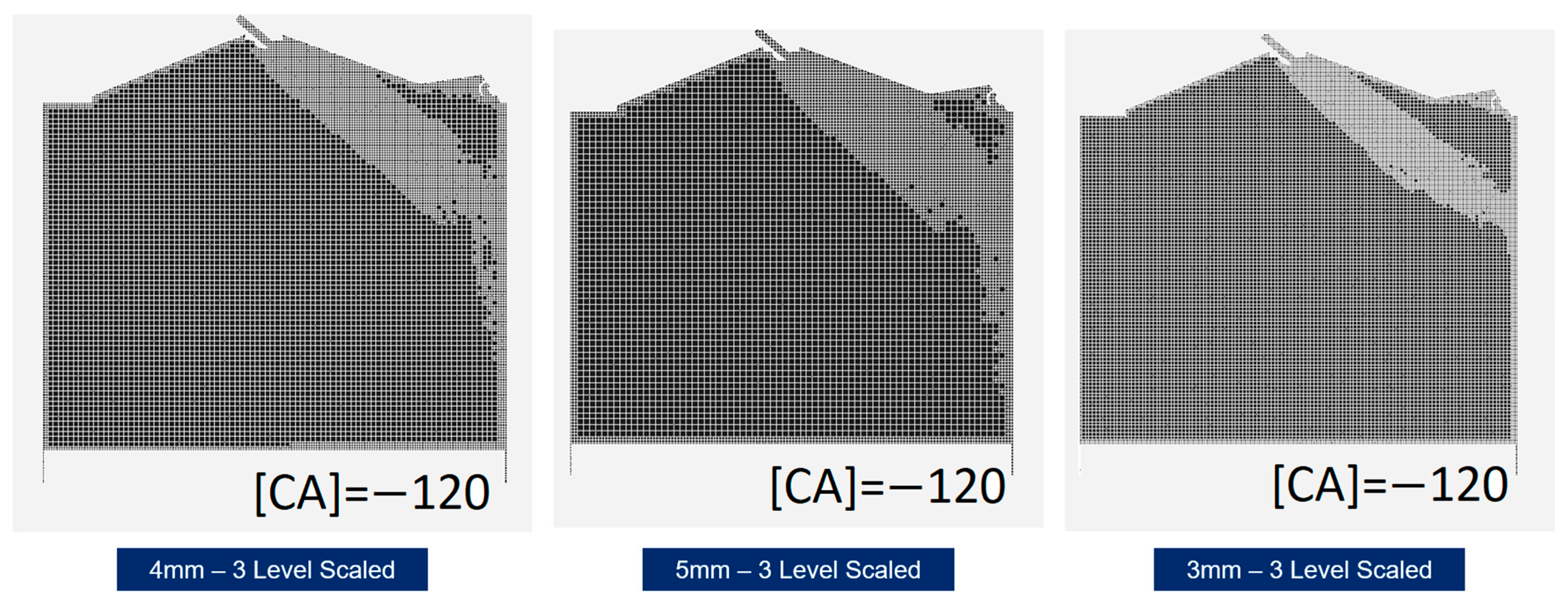
In this study, Converge CFD commercial software was employed with the adaptive mesh refinement (AMR) algorithm to accurately capture velocity and temperature gradients within the density-based transient CFD solver. Base mesh sizes of 3 mm, 4 mm, and 5 mm were utilized to investigate mesh independence for Sandia’s PIV validation case, thereby ensuring the accuracy of the fuel mixture prediction. For each base mesh size, local embedding and AMR techniques were applied with corresponding minimum cell sizes of 0.375 mm, 0.5 mm, and 0.625 mm, and maximum cell sizes of 0.75 mm, 1 mm, and 1.25 mm, respectively. An illustration of the refined mesh views for different base sizes is provided in
Figure 4, where a three-level refinement was applied in the injection region.
A three-level automatic refinement strategy was implemented based on velocity and temperature gradients in both the PIV validation and combustion CFD models. A semi-implicit numerical solver was selected to solve the transport equations, ensuring proper convergence and stability of the solutions.
Hydrogen combustion was modeled using the POLIMI_H2CO_1412 reaction mechanism developed by Chemical Reaction Engineering and Chemical Kinetics (CRECK) Group at Politecnico di Milano [
23,
24], specifically tailored for detailed hydrogen oxidation and consisting of 32 species and 173 elementary reactions. This mechanism, denoted as POLIMI_H2CO_1412, has been validated against experimental data for ignition delay times and laminar flame speeds in hydrogen and syngas mixtures under a wide range of pressures and equivalence ratios. Hydrogen injection was modeled to occur between −140 °CA and −70 °CA. A total of 70 mg of hydrogen per cycle was injected at a fuel temperature of 303.15 K. The intake port pressure was set to 2.65 bar, and the intake air temperature at the boundary was defined as 320 K. To establish lean combustion conditions, the global equivalence ratio was adjusted to achieve a lambda (λ) value of 2.1 across all simulations. Wall boundary conditions were defined using adiabatic assumptions, with fixed wall temperatures of 510 K for the piston and cylinder head, and 460 K for the liner. The intake port wall temperature was set to 340 K. These consistent boundary and initial conditions were used throughout the optimization process to ensure a controlled and comparable evaluation of injector design effects. The Stiff Arrhenius Gas-phase Equilibrium (SAGE) detailed chemical kinetics solver [
25] was utilized to resolve the full set of chemical reaction equations during the combustion event within Converge CFD. To ensure numerical stability and accuracy, a density-based compressible solver was employed, with the time step automatically adjusted based on a CFL number maintained between 1 and 2, thereby enabling convergence through a variable time-step approach. The reliability of the SAGE solver coupled with Converge CFD for hydrogen combustion modeling has also been demonstrated in previous research conducted by Y. Li et al. [
14], where similar operating conditions were used to investigate knock formation and combustion characteristics in a hydrogen-fueled direct injection engine. Moreover, the extended Zeldovich mechanism [
26] was employed to model thermal NO
x formation, capturing high-temperature nitrogen oxidation pathways accurately, which also showed validated performance in the same study [
14]. In this study, the RNG k-ε turbulence model was employed to simulate the hydrogen–air mixture behavior due to its proven accuracy in capturing turbulent jet evolution in hydrogen direct-injection engines. Notably, Argonne National Laboratory has validated this model against optical and numerical data, demonstrating strong agreement between CFD predictions and experimental jet penetration and dispersion trends [
27].
Additionally, two-level mesh refinement was applied over the combustion chamber walls to enhance the capture of flow separation phenomena in both the PIV validation and combustion cases. For ignition modeling, a spark event was initiated at −5 °CA before the top dead center (TDC) for optimization and full-cycle combustion simulations, targeting effective ignition within the designated spark region.
5. Flow Validation with PIV-CFD Comparison
In this study, Converge CFD commercial software was employed with the adaptive mesh refinement (AMR) algorithm to accurately capture velocity and temperature gradients within the transient CFD model. Base mesh sizes of 3 mm, 4 mm, and 5 mm were utilized to investigate mesh independence for Sandia’s PIV validation case, thereby ensuring the accuracy of the research.
Comparison metrics are essential for evaluating the flow distribution consistency between CFD simulations and PIV measurements within the cylinder. Accordingly, following the approach proposed by Scott et al. [
8], both global and local structure index metrics were employed in this study.
The Global Structure Index (GSI), defined in Equation (1), quantifies the average vectorial directional agreement (Vector Angle) across the measurement plane at corresponding nodes between CFD and PIV data. Similarly, the Global Magnitude Index (GMI), described in Equation (2), represents the average match in vectorial magnitudes (Vector Magnitude) between the two datasets at the respective nodes.
These indices are derived based on vector similarity principles, where GSI uses the cosine of the angle between velocity vectors and GMI evaluates the normalized magnitude difference at each node.
Furthermore, the sub-vectorial component formulations for both GSI and GMI metrics are presented in Equation (3), providing a detailed basis for assessing local flow field similarities.
This formulation [
8] was implemented in MATLAB v2024a code by interpolating from the CFD environment to the PIV measurement results. Thus, the CFD vector field results were compared and quantified using non-dimensional GSI and GMI metrics.
6. Optimization Model
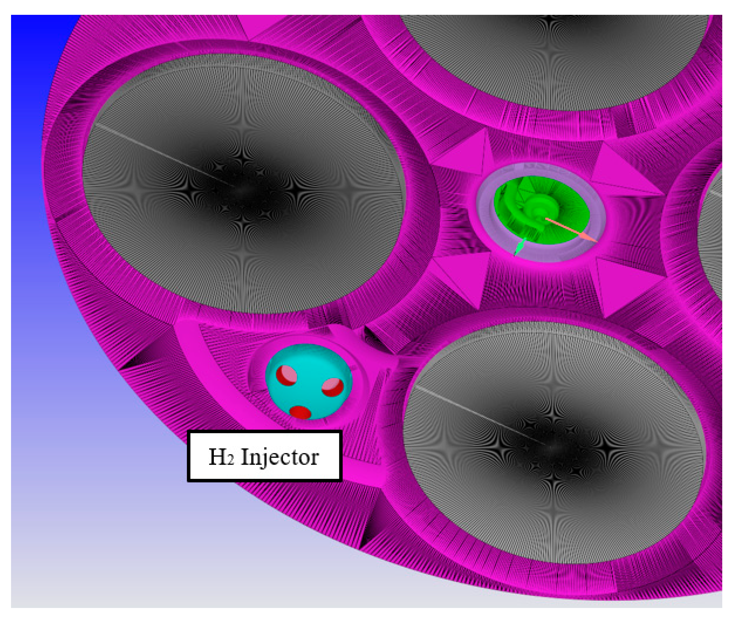
The in-cylinder control volume for each design was automatically generated by the optimization software. Each boundary condition corresponded to a geometric interface, as illustrated in
Figure 5. The injection angle and the number of injector holes were defined as optimization parameters and were directly linked to the geometric interface. The number of injector holes varied from three to five, and the injection angle was adjusted within the range of 15 to 33 degrees. These parameter limits were selected based on geometric feasibility and manufacturability considerations, ensuring that the optimized designs could be practically implemented. An illustration of the injection angle parameter setup is shown in
Figure 6.
A Kriging-based multi-objective genetic algorithm [
19] was employed as the optimization model, where brake mean effective pressure (BMEP) was targeted for maximization alongside the minimization of NO
x emissions. The Kriging surrogate modeling approach was selected due to its strong predictive accuracy and ability to estimate uncertainty in unexplored regions of the design space, which is particularly advantageous in CFD-based optimization where computational cost is high. Compared to polynomial response surfaces or radial basis function (RBF) models, Kriging offers more flexibility in capturing nonlinearities. This enables efficient and reliable convergence to the Pareto-optimal front using a limited number of CFD simulations.
Sixteen initial sampling designs were generated using the Latin Hypercube Sampling method [
20], and an additional six optimization iterations were introduced into the process. In total, 22 design iterations were successfully completed through full coupling between Converge CFD combustion simulations and the optimization software, ensuring robust evaluation of the proposed design parameters.
7. PIV Measurement and CFD Result Comparison of Research Engine
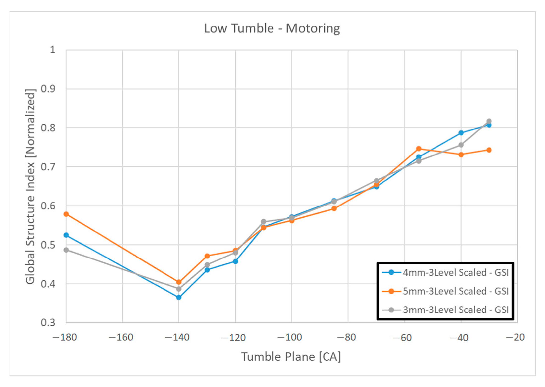
Three base mesh sizes 3 mm, 4 mm, and 5 mm were evaluated through PIV validation CFD simulations under motoring conditions (without injection), both with and without a tumble plate. A total of 18 simulations were conducted, and the results were compared using GSI and GMI metrics [
8] through MATLAB analyses. Each case was examined individually at crank angles of −180 °CA, −140 °CA, −130 °CA, −120 °CA, −110 °CA, −100 °CA, −85 °CA, −70 °CA, −55 °CA, −40 °CA, and −30 °CA, based on PIV data sourced from Sandia National Laboratories.
According to the GSI results, the match indices under motoring conditions were consistently similar across different mesh sizes, as shown in
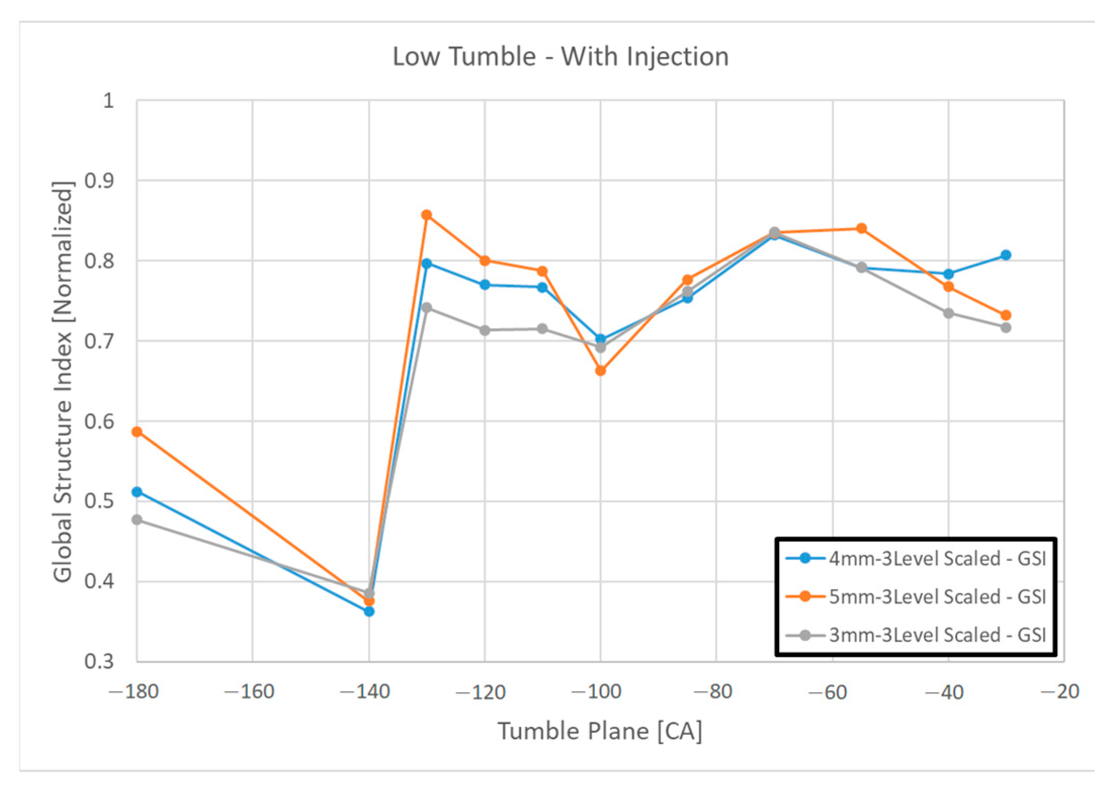
Figure 7. As the piston approached TDC, the GSI match index increased, reaching a maximum value of 0.8. A similar trend was observed for injection conditions without a tumble plate, as presented in
Figure 8, although in this case, the GSI match index remained around 0.75 from the beginning of the injection until the piston reached TDC.
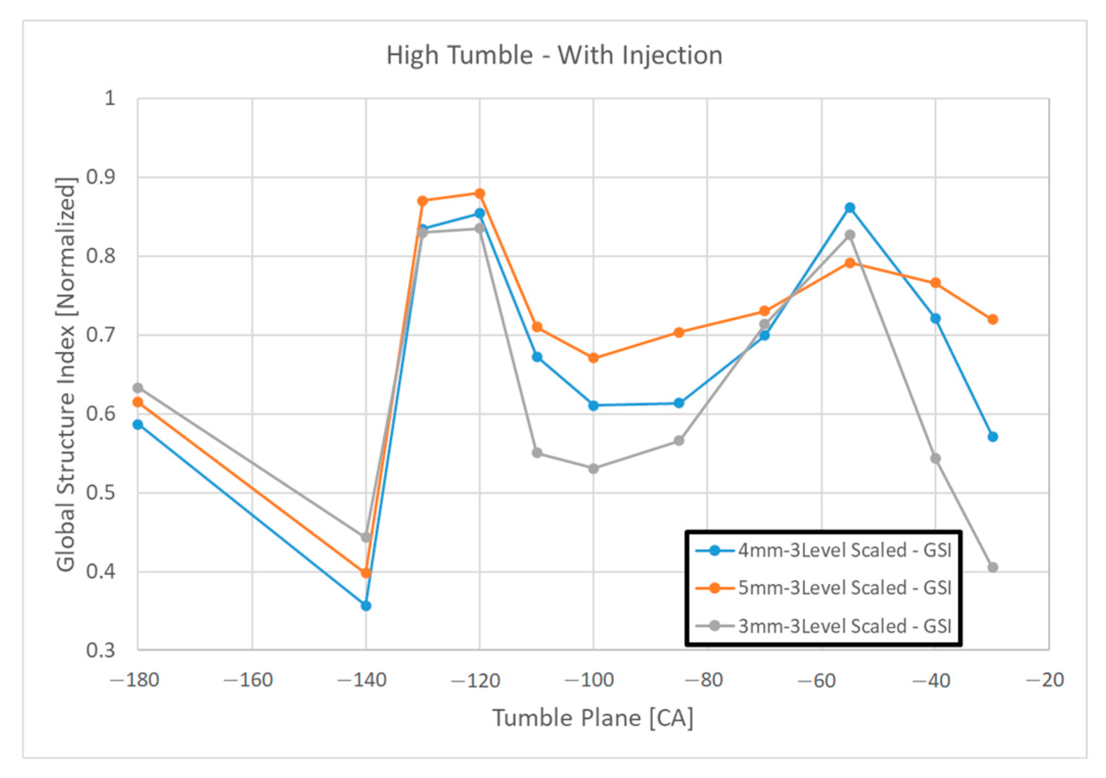
Under injection conditions with a tumble plate, the 5 mm base mesh produced the highest GSI match index, achieving values up to 0.7 at −30 °CA, outperforming the 3 mm and 4 mm cases, as illustrated in
Figure 9.
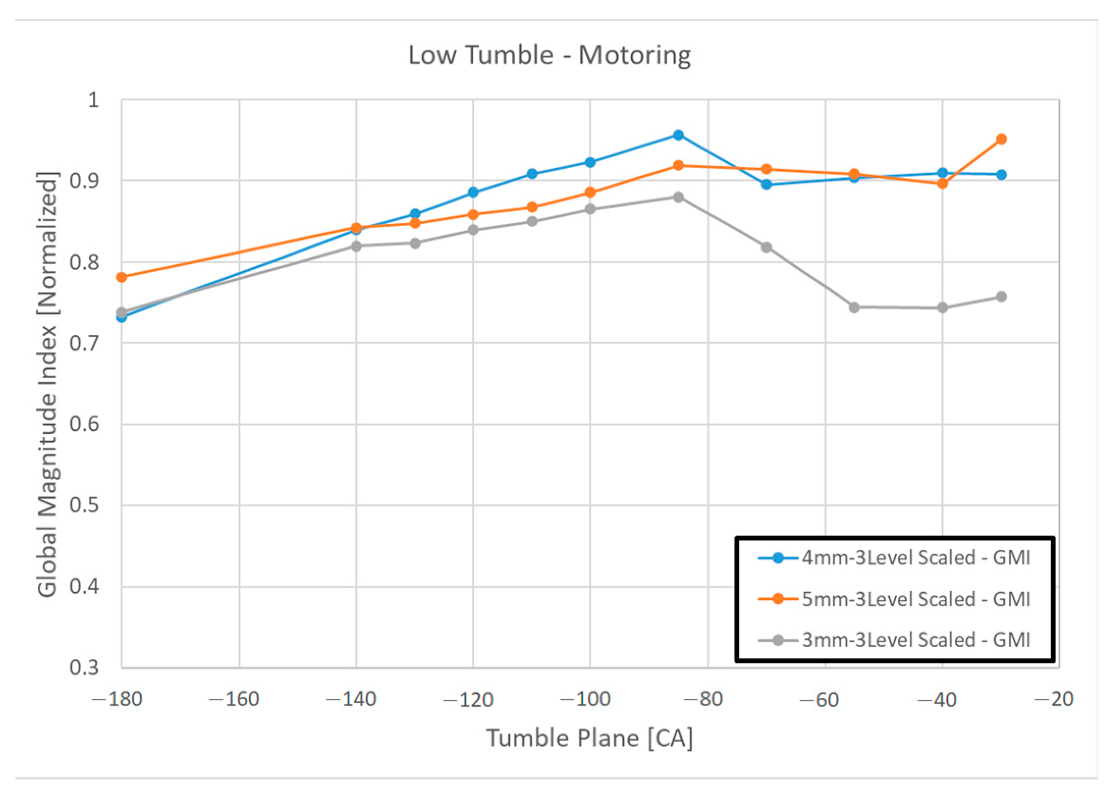
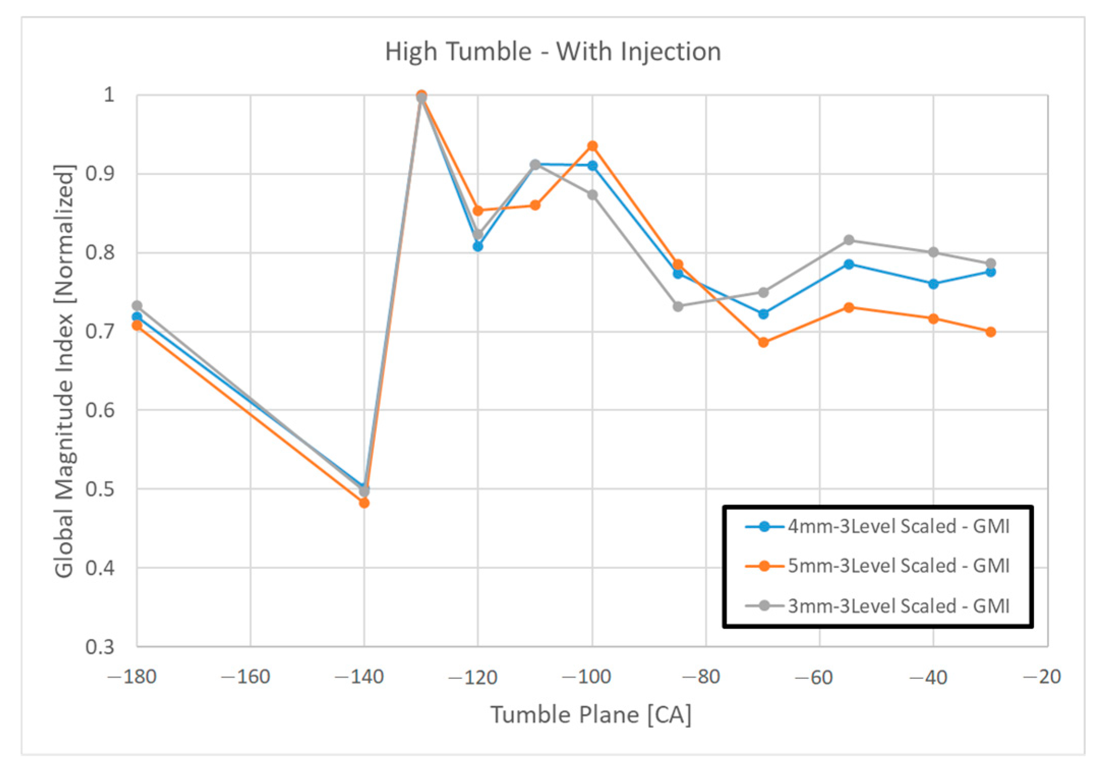
In terms of GMI analysis, slight variations were noted under motoring conditions. Specifically, for the 3 mm base mesh, the GMI match index declined to approximately 0.75 as the piston moved toward TDC, as shown in
Figure 10. Nevertheless, injection cases, both with and without a tumble plate, showed consistent GMI match trends across different mesh sizes, with match indices decreasing steadily from approximately 0.97 to 0.7, as depicted in
Figure 11 and
Figure 12.
Overall, when considering mesh independence and flow separation accuracy, the 5 mm base mesh size provided superior results, particularly under injection and tumble plate conditions that closely resemble actual engine operation. Moreover, the 5 mm mesh setting offered significant computational efficiency, making it the preferred choice for subsequent combustion optimization studies.
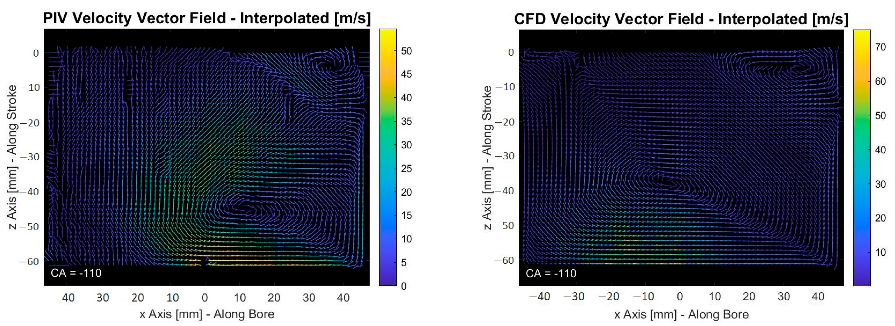
Additional validation of the 5 mm mesh was observed in the injection flow distribution over the measurement plane. Near the end of the injection event at −110 °CA, the CFD model successfully captured the tumble motion within the cylinder, as seen in
Figure 13. Although the k-epsilon turbulence model predicted that the tumble core slightly shifted to the left due to its known underprediction of shear stresses, the overall tumble structure and cavity motion remained well-aligned with experimental observations after the injection event, as illustrated in
Figure 14.
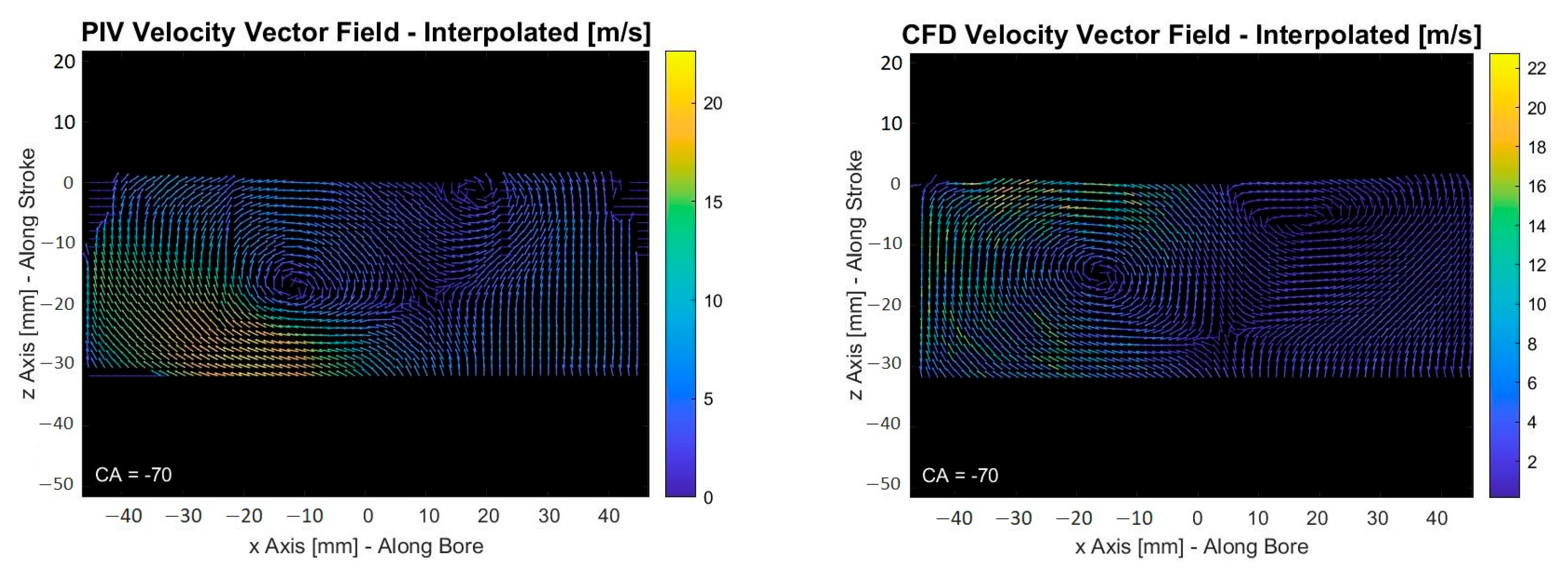
Figure 13 and
Figure 14 present comparative velocity vector fields from CFD simulations and PIV measurements at −110 °CA and −70 °CA, respectively. These phases correspond to the late injection and early compression stages, where tumble development and penetration-driven flow structures are most pronounced. Despite the RNG k-ε model’s known limitations in capturing near-wall shear stresses and anisotropic turbulence, both figures reveal strong consistency in large-scale flow structures.
In
Figure 13, the tumble vortex core is reproduced with reasonable fidelity in terms of orientation, shape, and recirculation zone dimensions. While a slight lateral offset is observed compared to PIV data particularly near the upper liner region, this deviation is within acceptable bounds given the model’s averaged turbulence formulation and the mesh resolution constraints.
Figure 14, recorded closer to the top dead center, demonstrates the evolution of the tumble vortex into a more compressed, centrally located toroidal structure. The CFD results again reflect this dynamic behavior, albeit with slightly reduced peripheral vortex strength near the wall boundaries, which is attributable to the RNG k-ε model’s underestimation of wall-bounded shear interactions.
Nevertheless, the spatial coherence of the tumble centerline, rotational symmetry, and vertical velocity gradients are well-aligned with experimental measurements. These results indicate that although fine-scale shear-layer effects may be somewhat smoothed, the dominant aerodynamic features that govern in-cylinder mixture preparation and flame front development are accurately captured.
This captured tumble motion is critical for the subsequent combustion phase, as the distribution of the H2 and O2 mixture mass fractions before spark ignition directly influences flame propagation behavior.
In conclusion, the 5 mm base mesh configuration was confirmed to provide the best compromise between computational cost and flow structure accuracy, ensuring reliable turbulence representation for subsequent hydrogen combustion simulations.
8. Results of the Optimization Study
A Kriging-based surrogate multi-objective genetic algorithm [
19] was successfully employed to complete 22 optimization cases. This approach efficiently achieved the targeted objectives with a reduced number of design parameters, as summarized in
Table 3. The results indicate that the optimization process converged towards global optima for both enhanced engine performance and reduced NO
x emissions, particularly for design iterations 21 and 22.
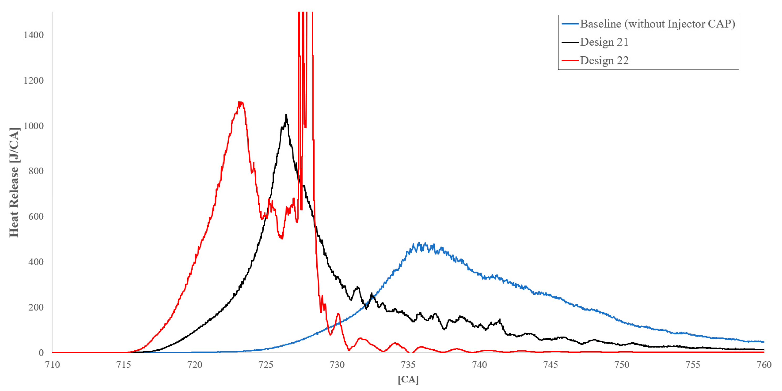
However, further analysis revealed that Design 22 exhibited a tendency towards knocking, as indicated by the abnormal heat release profiles shown in
Figure 15. In contrast, Design 21 displayed no signs of critical heat release, highlighting its superior combustion stability.
To quantitatively assess knock tendency, the maximum pressure rise rate
was employed as a knock index. This parameter is commonly used to capture high-frequency pressure oscillations associated with abnormal combustion in hydrogen-fueled engines. As shown in
Table 3, Design 21 exhibited a relatively low
value of 11.5 [bar/°CA], confirming its favorable combustion characteristics compared to higher values observed in other cases, such as that Design 22 has 36.2 [bar/°CA].
Additionally, the burned fuel mass fraction analysis demonstrated that combustion in the baseline case did not complete within +50 [CA] after the top dead center (TDC), whereas Design 21 achieved complete combustion of the injected hydrogen within this interval.
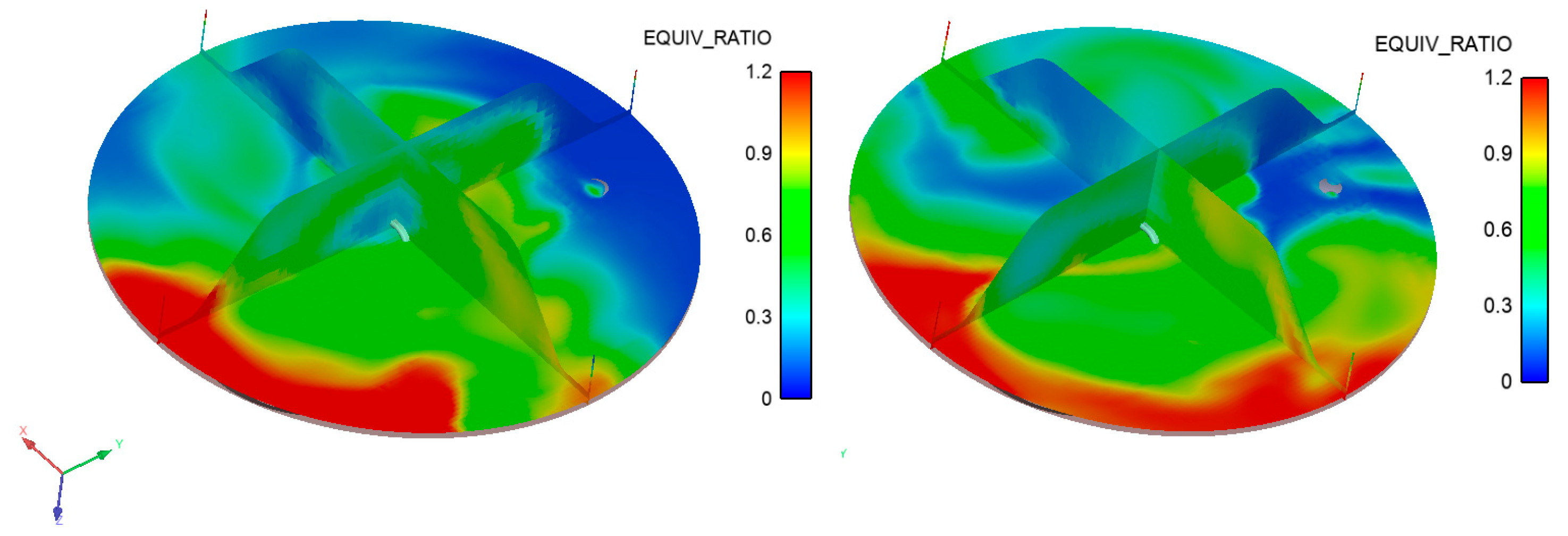
Equivalence ratio distribution analyses, illustrated in
Figure 16 above, further support these findings. In the baseline (no-hole) configuration, the air–fuel mixture near the spark plug region remained excessively lean. Conversely, Design 21 achieved an equivalence ratio of approximately 0.6 in the spark vicinity, ensuring sufficient flammability and improved ignition reliability.
9. Full Cycle Comparison Results
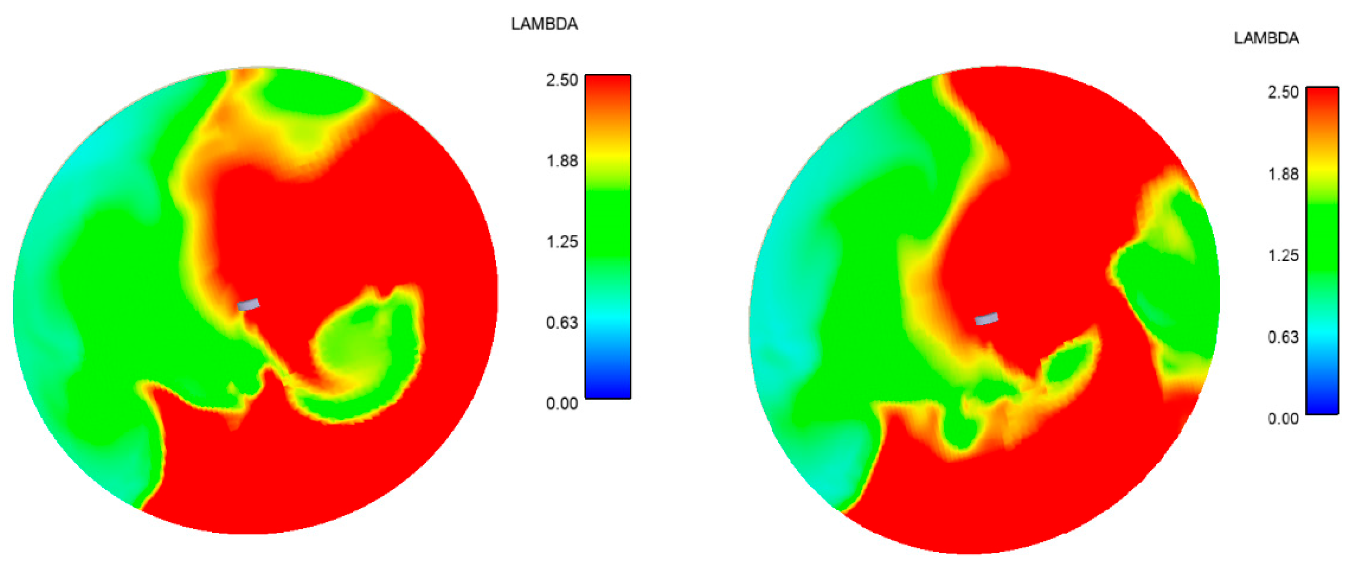
Comprehensive full-cycle CFD simulations (2160 [CA]) were performed for both the baseline and Design 21 configurations to assess the impact of valve timing events on engine performance. Despite targeting a lambda value of 2.15 at the end of the injection phase, the baseline case (absent an injector hole configuration) exhibited misfire during the first and third cycles. This was attributed to excessively lean conditions near the spark plug region, where local lambda values exceeded 2.5, as depicted in
Figure 17. In contrast, Design 21 achieved consistent ignition across all three cycles.
The hydrogen injection strategy aimed to deliver approximately 70.144 mg of fuel per cycle. Nevertheless, in the baseline case, approximately 7.23 mg of unburned fuel remained trapped within the cylinder following the first cycle due to incomplete expulsion during the exhaust event. Consequently, the second cycle experienced an unintended increase in the effective fuel quantity by approximately 10%, leading to abnormal combustion characteristics and a propensity for knocking, as previously illustrated in
Figure 15.
Despite the additional fuel contribution from the first cycle, combustion during the second cycle proceeded effectively, resulting in comparable specific fuel consumption values between the baseline and Design 21 cases, as summarized in
Table 4 above. Additionally, in the optimization study, NO
x emissions were evaluated based on the cumulative in-cylinder NO
x mass at +50 °CA after TDC. For the full-case comparison between the baseline and Design 21, total NO
x was calculated as the time-dependent cumulative NO
x mass released through the exhaust port over the full 720 °CA cycle.
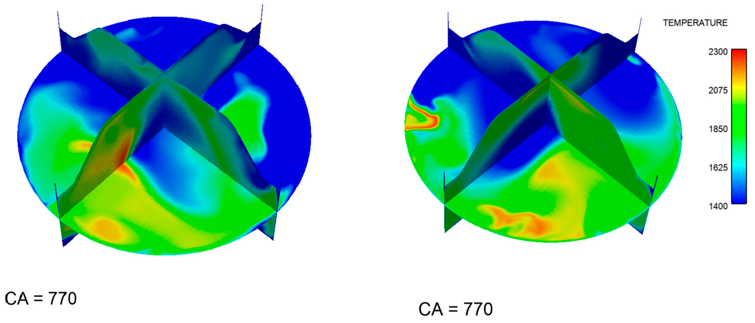
Thermal NOx formation in hydrogen-fueled combustion is highly sensitive to localized high-temperature regions, particularly where post-flame gases remain above 1800 [K] for extended durations. At +50 °CA ATDC, the combustion process is nearly complete, and the spatial temperature field reflects the thermal environment that governs NOx accumulation.
Figure 18 shows that in the baseline injector configuration, large volumes of gas remain at temperatures above 1800 K, especially in peripheral regions of the combustion chamber. These areas indicate that hot gases are not only generated but also persist near the chamber walls and corners, where mixing and convective heat loss are less effective. The extended exposure of these gas volumes to high temperatures facilitates the time-integrated chemical pathways for NO
x formation, especially in the presence of excess oxygen under lean conditions.
In contrast, the optimized Design 21 confines the highest temperature zones near the chamber center, minimizing both the spatial extent and the residence time of gases in NOx-prone temperature ranges. The thermal field in this case is more symmetric and centralized, reducing heat transfer to walls and suppressing localized hot spots. This leads to two primary benefits: first, decreased cumulative NOx production due to shorter exposure to critical thermal thresholds, and second, improved combustion completeness through more uniform mixing and flame propagation.
In addition to the performance and emissions metrics, knock intensity was assessed using the maximum pressure rise rate , which serves as a practical indicator of combustion aggressiveness and knock tendency in hydrogen-fueled engines. This parameter enables tracking of peak in-cylinder pressure gradients across the combustion cycle and is commonly used in numerical and experimental studies.
As shown in
Table 3, the baseline configuration yielded a higher knock index of 64.7 bar/°CA, while the optimized Design 21 resulted in a lower value of 17.3 bar/°CA. Although this does not represent a complete suppression of knock, the lower peak pressure gradient suggests comparatively smoother combustion behavior under the same full-load conditions.
This observation is consistent with the thermal distribution trends seen in
Figure 18, where Design 21 exhibited a more compact high-temperature region, reducing the likelihood of localized hot spots that could trigger knock. These results indicate that injector geometry, specifically the inclination angle and hole count, can influence not only emissions but also combustion stability, particularly under lean LPDI hydrogen combustion conditions.
These physical observations, supported by the CFD temperature fields, directly explain the reduced NOx output observed in Design 21 without invoking advanced combustion strategies or EGR. In addition to emission control, the more uniform heat distribution and reduced local temperature peaks also contribute to improved combustion stability and lower knock tendency, since hydrogen knock is highly sensitive to localized hot spots and inhomogeneities in the mixture. Thus, the injector geometry’s influence on post-combustion heat distribution is a key factor in both emission reduction and abnormal combustion suppression under LPDI hydrogen combustion regimes.
Notably, while the baseline configuration achieved only one complete combustion event across three cycles, Design 21 consistently demonstrated stable combustion behavior throughout. This performance underscores the superior sustainability and robustness of Design 21 with three holes and a 15.24 [deg] injection angle. Moreover, Design 21 achieved a reduction in specific emissions by approximately 39.4% relative to the baseline case, primarily attributed to a higher in-cylinder equivalence ratio exceeding 1.2.
10. Conclusions
This study aimed to advance the design of an environmentally sustainable combustion chamber by enabling the controlled combustion of highly diffusive fuel, such as hydrogen, within an internal combustion engine. Based on validated PIV-CFD comparisons of the hydrogen air–fuel mixture, optimization of the injector hole configuration embedded in the CAP design was performed, with a focus on enhancing both performance and emissions characteristics.
The findings highlight that
Enhancing in-cylinder tumbling motion significantly improves cycle-to-cycle variations and reduces the risk of misfire. Varying injection angles promote more homogeneous air–fuel mixing through enhanced tumble flow, resulting in more stable and consistent combustion.
Although a target lambda value of 2.15 was adopted to ensure stable combustion, this parameter alone proved insufficient due to the inherent diffusivity of hydrogen. Baseline analyses demonstrated that irregular air–fuel distribution can lead to misfire or knocking tendencies across different cycles.
Cycle-to-cycle variations further revealed that unburned fuel trapped within the cylinder, resulting from improper valve timing, can lead to incomplete expulsion during the exhaust phase. This underscores the critical importance of optimizing valve timings during the preliminary design phase to avoid combustion instabilities, such as backfire.
Finally, the optimization strategy implemented in Design 21, featuring three injector holes and a 15.24° injection angle, successfully achieved a more homogeneous in-cylinder mixture, maintaining the equivalence ratio below 1.2.
As a result, NOx emissions were significantly reduced, with a decrease of approximately 39.4% compared to the baseline configuration. Furthermore, the design led to notable improvements in combustion stability and engine performance by mitigating cycle-to-cycle variations and significantly reducing the risk of misfire. These findings underscore the effectiveness of targeted injector and combustion chamber design modifications in advancing hydrogen-fueled engine technology.
The outcomes of this study offer practical implications for engine designers working with hydrogen-fueled heavy-duty engines. By focusing on manufacturable parameters such as the number of injector holes and their inclination angles, the presented optimization framework enables the fine-tuning of injector designs without altering the base injector architecture or requiring higher injection pressures. This ensures compatibility with current LPDI systems while achieving measurable improvements in both combustion performance and NOx emissions. As such, the findings support data-driven decision-making in injector calibration and design workflows under lean hydrogen combustion conditions.
However, certain limitations of the current study must be acknowledged to ensure balanced interpretation of the results. The simulations were conducted under full-load and steady-state conditions, without accounting for transient effects or cycle-to-cycle variability. The EGR level was kept constant at 2.6% throughout the optimization process, and no aftertreatment systems or combustion control strategies (e.g., spark timing, injection phasing) were included. Furthermore, the optimization was intentionally restricted to geometric parameters; namely, the number of injector holes and their inclination angles in order to focus on variables that are both manufacturable and directly applicable within current LPDI architectures. This design constraint ensures that the findings can be realistically implemented without requiring significant modifications to existing engine hardware or control strategies.
11. Future Works
This study was carried out at full-load operation using a fixed EGR rate and injection pressure representative of a low-pressure direct injection (LPDI) strategy. Future work may extend the proposed surrogate-assisted optimization methodology to a broader parametric space, including variable EGR levels and injection pressures, to assess their nonlinear interactions with NOx formation pathways and engine performance indicators. Additionally, integrating the optimization framework into transient cycle simulations and part-load operating regimes could support the development of real-time control strategies for hydrogen-fueled engines.


