Article

Fuzzy Model Predictive Control for Unmanned Helicopter

by
Łukasz Kiciński
1,*,† and
Sebastian Topczewski
2,†
1
Faculty of Power and Aeronautical Engineering, Warsaw University of Technology, ul. Nowowiejska 24, 00-665 Warsaw, Poland
2
Faculty of Power and Aeronautical Engineering, Institute of Aeronautics and Applied Mechanics, Warsaw University of Technology, ul. Nowowiejska 24, 00-665 Warsaw, Poland
*
Author to whom correspondence should be addressed.
These authors contributed equally to this work.
Appl. Sci. 2025, 15(14), 8120; https://doi.org/10.3390/app15148120
Submission received: 15 June 2025 / Revised: 7 July 2025 / Accepted: 14 July 2025 / Published: 21 July 2025
(This article belongs to the Special Issue Advances in Aircraft Design, Optimization and Flight Control)

Abstract

Unmanned helicopters, due to their agility and strong dependence on environmental conditions, require using advanced control techniques in order to ensure precise trajectory tracking in various states of flight. The following paper presents a methodology for the design of an unmanned helicopter flight controller. The proposed solution involves the use of the Model Predictive Control framework enhanced with the Takagi–Sugeno inference algorithm. The designed system uses a Parallel Distributed Compensation architecture and utilizes multiple linear dynamics models to precisely model the helicopter’s response in transitioning from hovering to forward flight. The proposed control system was developed for the ARCHER unmanned rotorcraft, which was designed at Warsaw University of Technology. In order to evaluate control efficiency, simulation tests were conducted using the helicopter mathematical model built in the FLIGHTLAB environment, fully integrated with the Matlab/Simulink platform. The control system test results, including system step responses and performance during flight over a predefined path, highlight the differences between the conventional Model Predictive Control regulator and its fuzzy-enhanced variant.

1. Introduction

The history of Unmanned Aerial Vehicles is inseparably connected to the history of conventional aviation. In their initial applications, for example, they were commonly used in the training of British artillery troops, as exemplified by the history of the de Havilland DH82B “Queen Bee” aircraft [1]. Over the years, apart from conventional fixed-wing UAVs, the industry has expanded with many alternative designs, like conventional rotorcrafts, quadrotors, and even ornithopters and entomopters [2]. Obviously, the choice of vehicle configuration is highly dependent on the type of mission that has to be performed. Today, UAVs are widely used in areas such as remote sensing, transportation, search and rescue, and many more. In this broad field, rotorcrafts stand out for their ability to hover and to perform vertical take-offs and landings. This capability enables them to operate precisely in confined spaces, which makes them a natural choice for rescue missions.

1.1. Motivation

Apart from the many advantages of helicopters, helicopter dynamics are highly dependent on environmental conditions and show significant differences across various flight states. In addition to well-known flight dynamics principles expressed by the equations of helicopter motion [3], there are various phenomena that affect rotorcraft behavior, which are described in the text below.
A key example is the occurrence of the vortex ring state during the descent of the helicopter at low forward speeds. A vortex ring state occurs when the rotor produces a recirculating flow, where the induced downwash interacts with the incoming air, forming a toroidal vortex around the rotor disk. The formation of this phenomenon leads to low-frequency oscillations of the main rotor, which can result in potential control problems and loss of stability. Since this phenomenon highly affects the behavior of a rotorcraft, it is necessary to properly model the vortex ring state while analyzing helicopter dynamics. A proposed methodology for modeling the vortex ring state is presented in reference [4].
Another example of varying helicopter dynamics in different flight conditions is the occurrence of dissymmetry of lift on the main rotor during forward flight. Advancing blades experience much higher airflow velocities than retreating blades, leading to unequal lift on opposite sides of the rotor disc. These flight conditions not only create blade flapping and rotor vibrations but can also lead to stalling in the retreating blades and rapid rolling of the helicopter.Detailed computation of asymmetric lift loads on the main rotor during forward flight using the finite volume method is described in reference [5].
Since the rotorcraft’s ability to generate thrust is based on inducing downward-directed airflow velocity, helicopters operating near the ground experience an increase in lift force due to the ground effect. The airflow induced by the main rotor stagnates near the ground, creating an area of increased static pressure. This effect is highly dependent not only on altitude but also on flight velocity. As forward flight velocity increases near the ground, a horseshoe-shaped ground vortex forms in front of the rotor. At sufficiently high speeds, this vortex is suddenly swept back under the helicopter, and the ground effect no longer contributes to the lift generation. Guidelines for modeling the ground effect are presented in reference [6], and various methods for modeling wakes in rotorcraft dynamics are presented in the paper cited in [7].

1.2. Methods of Designing Control Systems for Unmanned Rotorcrafts

Knowing that the aerodynamic phenomena describing helicopter dynamics strongly depend on the conditions in which the machine operates, it is necessary to use this knowledge to synthesize control laws that enable controlling the rotorcraft’s state in various distinct flight scenarios.
There are many alternative approaches for designing automatic flight control systems for rotorcraft. A literature study regarding this topic is presented below.
A reliable method of designing an automatic flight control system for an unmanned rotorcraft is to perform system identification of the plant in hover conditions and design PID regulators to achieve the desired position-tracking capabilities. This approach was precisely described in reference [8] and enabled designers to achieve satisfactory performance in conditions akin to hovering.
An alternative approach to synthesizing a control law for an unmanned rotorcraft can rely on H control loop design, which aims to minimize the impact of system disturbances on the helicopter’s performance. This task is mathematically described as the Bounded L 2 Gain Design Problem. This method not only guarantees the stability of the designed control system but also provides an efficient solution for controlling Multiple Input–Multiple Output (MIMO) plants, where dynamics decoupling is not possible. A description of designing a static H controller for an unmanned rotorcraft is presented in reference [9].
Another possible method for designing an automatic flight control system for an unmanned rotorcraft is based on Linear–Quadratic Regulator (LQR) theory, which aims to provide a static control law for MIMO plants [10]. Based on a linear dynamics model of the helicopter, the LQR regulator provides optimal control for an infinite time horizon [11]. The existence of an analytical solution for the LQR problem and its great efficiency in controlling MIMO dynamics make this method a popular choice in the aerospace industry [12]. An example of using the LQR framework in unmanned helicopter control is described in reference [13].
The previously mentioned methods for designing automatic flight control systems heavily rely on the mathematical representation of helicopter flight dynamics. An alternative approach to synthesizing control laws that do not necessarily rely on a mathematical model of the plant is the utilization of fuzzy inference systems. These systems can be designed based on expert knowledge and provide a suitable framework for designing nonlinear control laws. Reference [14] presents a process for designing a fuzzy inference system to control an unmanned rotorcraft. Another example of using fuzzy systems in unmanned helicopter control is reference [15], which describes the integration of a Mamdani regulator with Takagi–Sugeno inference for controlling the horizontal velocity of an unmanned rotorcraft.
In recent years, data-driven methods have gained significant popularity in the synthesis of control laws for autonomous systems. As one of them, reinforcement learning (RL) has emerged as a particularly promising framework for defining control policies in scenarios, where explicit modeling of complex dynamics is difficult or impractical. By interacting with the environment and learning through trial-and-error, RL agents can adapt to a wide range of flight conditions and disturbances. The application of RL to control tasks under strict constraints and safety requirements has led to the development of algorithms such as FHCPL, which enables fixed-horizon constrained policy learning in risk-sensitive industrial scenarios [16]. In the context of autonomous driving, similar principles have been successfully applied to motion planning using fixed-horizon constrained reinforcement learning techniques [17]. For aerial vehicles, hybrid approaches combining RL with trajectory optimization have been shown to significantly enhance path planning efficiency, as described in [18]. To improve learning performance and safety, frameworks like TAG incorporate teacher-advice mechanisms and Gaussian processes [19], while algorithms such as those presented in [20] aim to ensure almost-sure safe exploration by incorporating state safety estimation mechanisms. These advances demonstrate the growing viability of RL-based methods in automatic flight control, particularly for highly dynamic and uncertain environments where conventional controllers face limitations.
Apart from the presented approaches, an automatic flight control system for an unmanned helicopter can rely on Model Predictive Control, which is an advanced method of controlling dynamical systems. In its early applications, Model Predictive Control was widely utilized in controlling refinery processes, but nowadays, it has applications in industries such as metallurgy, aviation, robotics, nuclear engineering, and many more.
There are many applications of Model Predictive Control in unmanned rotorcraft systems. This technique strongly depends on the quality of the mathematical representation of the plant’s dynamics, but on the other hand, it has many formulations and provides the designer with a wide variety of weighting factors that shape the response of the designed system.
Reference [21] serves as an example of utilizing the Model Predictive Control framework for designing an automatic flight control system for an unmanned rotorcraft. It discusses the usage of Laguerre functions to define control signals produced by the regulator and compares the usage of unconstrained optimization in the algorithm with constrained optimization.
A possible enhancement of the standard MPC algorithm, known in the literature as robust MPC, is presented in reference [22], where the optimization task performed by the controller is defined as the minimization of the worst-case deviation along the predicted trajectory. The paper describes the synthesis of an automatic flight control system for an unmanned rotorcraft using robust MPC and experimentally evaluates its performance.
Since Model Predictive Control is defined as an optimization task, it is possible to formulate it using a nonlinear mathematical model of the controlled plant. An approach known as Nonlinear MPC produces a control signal in the process of solving a nonlinear and non-convex optimization problem instead of a quadratic programming task, as in the conventional variant of this method. Reference [23] shows an application of this approach to controlling an unmanned rotorcraft, where the optimization problem in the MPC framework is solved using the Proximal Averaged Newton for Optimal Control algorithm, presented in [24].
Precise control of unmanned helicopters enables their effective operation in complex and dynamic environments, where integration with other networks such as energy and transportation is essential to ensure system reliability and resilience [25]. Moreover, precise control allows unmanned systems to operate in swarms, where advanced multi-agent cooperation methods, such as asymmetric Nash games, enable efficient task and resource allocation under varying environmental conditions [26]. As a result, these approaches enhance the adaptability and scalability of unmanned helicopter control systems.
The research presented in this paper intends to show that Model Predictive Control, enhanced with Takagi–Sugeno inference, can be an efficient method for controlling an unmanned helicopter in changing environmental conditions, such as varying forward-flight velocities. In the aerospace industry, most commercial automatic flight control systems rely on PID controllers, which require designing a complex system architecture. The utilization of Model Predictive Control with Takagi–Sugeno inference provides a centralized regulator that can ensure sufficient control without the need for a complicated system design.
The novelty of this research lies in the development of an automatic flight control system for a small unmanned rotorcraft that employs a Parallel Distributed Compensation approach. It relies on designing multiple Model Predictive Control regulators for different operating conditions and produces a control signal using the Takagi–Sugeno inference algorithm. The proposed method is tested using a nonlinear model of helicopter dynamics built in the FLIGHTLAB environment, which provides detailed information about various phenomena affecting the rotorcraft’s flight.

2. Materials and Methods

2.1. Control Plant Description

The proposed control system was designed for the ARCHER unmanned helicopter. This is a small-scale rotorcraft, which was designed and built at the Warsaw University of Technology in 2018. Its name stands for Autonomous Reconfigurable Compound Helicopter for Education and Research [27]. The ARCHER was originally built in the classical configuration with a main rotor and tail rotor for flight control. Apart from this, the main purpose of the described aerial vehicle is to be easily modified by attaching to its main structure additional control effectors or aerodynamical surfaces, to expand its application range. In Figure 1, the ARCHER helicopter with an additional pushing propeller is presented.
For the purpose of this research, ARCHER is considered in its standard form, where the main carrier module consists of the fuselage, propulsion and power distribution system, main rotor, tail rotor, and rigid landing gear. Both rotors are powered by separate electric motors, which enables them to rotate at individual angular velocities independently, without using advanced powertrain construction. The ARCHER uses a see-saw rotor hub, which is a popular solution in small helicopters. The main rotor blades are designed using NACA23012 airfoils and the tail rotor blades are shaped using symmetrical NACA0015 airfoils. ARCHER’s main rotor rotates in the clockwise direction. The basic geometrical and mass characteristics of ARCHER helicopter are presented in the table below (Table 1).

2.2. Simulation Model Description

A popular and reliable approach in creating simulation models in the mechanical engineering industry, especially in motion simulators, relies on a modular architecture approach [29]. The basic purpose of this framework is to separately model the main components of the simulated machine and to define relations between these objects.
In the case of modeling helicopter dynamics, these separate modules can be, for example, the following:
  • Fuselage dynamics (considered as a 6DOF rigid body).
  • Main rotor dynamics.
  • Tail rotor dynamics.
  • Landing gear dynamics (for modeling ground contact).
  • Powertrain dynamics (which combines engine dynamics and power transmission description).
  • Atmosphere model.
  • Actuators dynamics.
The modular architecture enables precise modeling of the state of multiple helicopter elements and defining mutual relations between modeled objects.
FLIGHTLAB 3.7.1 software is a professional simulation environment, created by Advanced Rotorcraft Technologies Inc., that enables its users to create detailed mathematical representations of rotorcrafts using a modular architecture. It is a reliable tool for considering phenomena such as the occurrence of wakes created by the main rotor, ground effect, retreating blade stalling, and others, which makes FLIGHTLAB a powerful piece of software for helicopter modeling [30].
In this research, the FLIGHTLAB environment was used to create a detailed ARCHER model, which can be used to test the performance of the designed control system.
In order to model the helicopter’s main rotor, the blade element method was used to determine aerodynamic loads. Knowing the blade’s airfoils, it was possible to precisely describe lift force, drag force, and pitching moment on the main rotor as nonlinear functions of dynamic pressure, angle of attack, and Mach number. They were approximated using lookup table data, coming from detailed main rotor analysis using CFD methods. In order to determine the induced velocity, the Peters–He six-state model was utilized [31].
While modeling the tail rotor, disc theory was used to determine the rotor’s thrust. The choice of technique was motivated by the computational efficiency of this method.
The fuselage was assumed to be a rigid body with six degrees of freedom. Its mass properties, such as the center of gravity position, inertia matrix, and total mass, are included in the numerical model. Similarly, as in the main rotor case, the aerodynamic loads on the fuselage were determined using lookup tables. In this variant, aerodynamic forces and moments were described as nonlinear functions of dynamic pressure, angle of attack, and sideslip angle. The fuselage model also includes information about the sensor position.
The utilized numerical model of the helicopter provides information about the landing gear mechanics, which enables the analysis of landing maneuvers. The friction of the skids against the ground is considered.
In order to simulate environmental conditions during flight, FLIGHTLAB enables its users to utilize the 1959 ARDC atmospheric model, which is based on the hydrostatic equations and ideal gas laws. The proposed research omits the occurrence of turbulence.
The resulting ARCHER model, which consists of the elements described above, is characterized by 26 state variables:
  • Helicopter’s position in the inertial coordinate system (3).
  • Helicopter’s linear velocities in the body-fixed coordinate system (3).
  • Integrals of linear velocities in the body-fixed coordinate system (3).
  • Helicopter’s fuselage attitude angles (3).
  • Helicopter’s fuselage angular velocities (3).
  • Integrals of angular velocities (3).
  • Induced velocity components: uniform, zeroth harmonics, first harmonics (sine and cosine), and second harmonics (sine and cosine) (6).
  • Induced flow state of the tail rotor (1).
  • Coning angle of the tail rotor (1).

3. Control Methodology

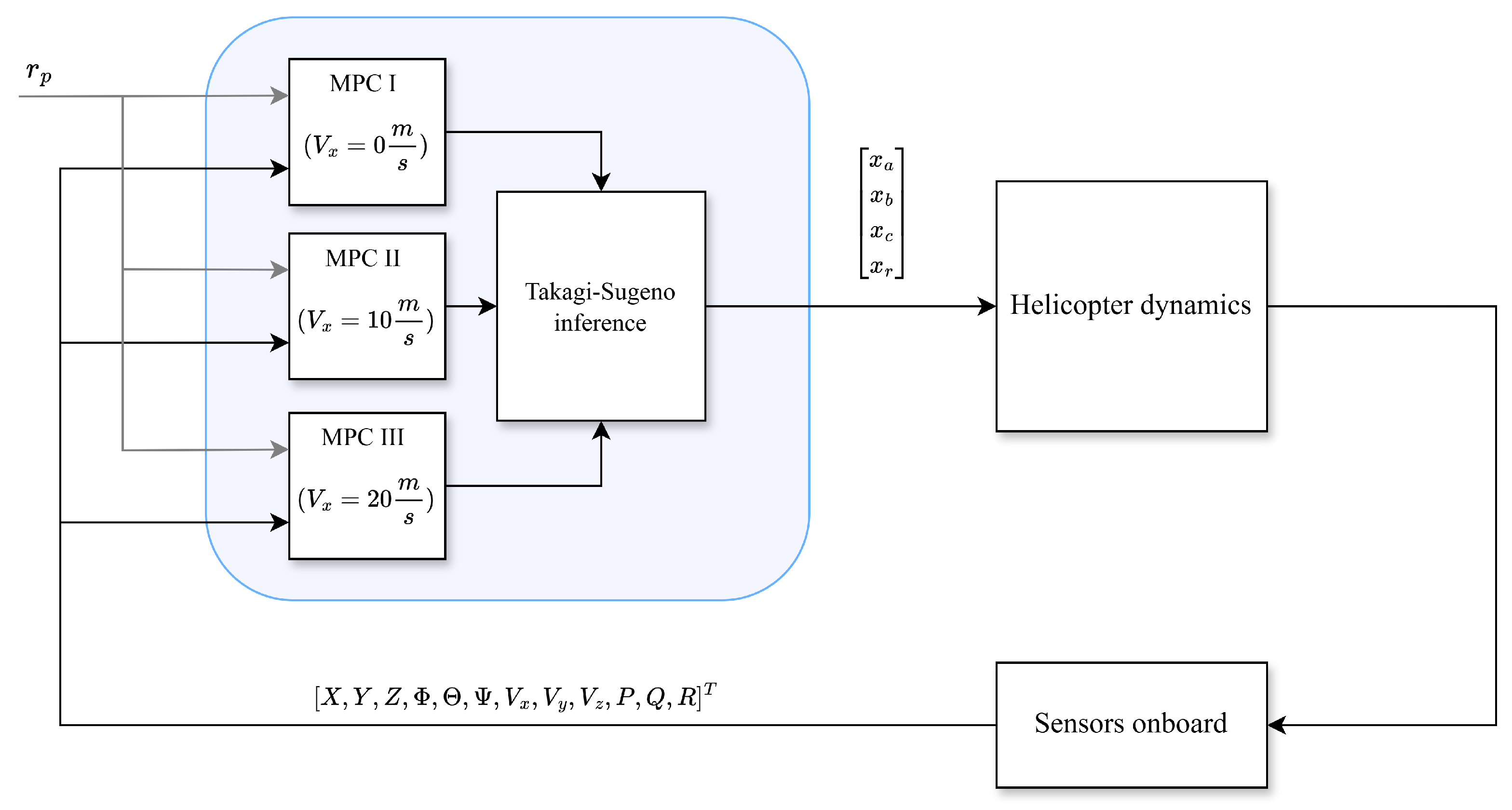
The methodology used in the presented approach relies on the Parallel Distributed Compensation (PDC) technique, which corresponds to utilizing multiple regulators, tuned for different operating conditions [32]. In this method, signals computed by several algorithms are combined in order to generate final control signal. The high-level control system scheme is presented in Figure 2.
The proposed system is a full-state feedback control loop, which as input signals employs the reference state space trajectory vector r p and the measured state vector, which consists of the following:
  • [ X , Y , Z ] —position of the unmanned rotorcraft in the inertial reference coordinate system.
  • [ Φ , Θ , Ψ ] —attitude (roll, pitch, yaw) angles of the rotorcraft with respect to the reference coordinate system.
  • [ V x , V y , V z ] —linear velocities measured in the body-fixed coordinate system.
  • [ P , Q , R ] —angular velocities of the rotorcraft.
The computed control vector u stores the information about
  • x a , x b —cyclic pitch components of the main rotor;
  • x c —collective pitch of the main rotor;
  • x r —collective pitch of the tail rotor.
In this instance, control laws are defined for different forward flight velocities ( V x r e f = [ 0 , 10 , 20 ] [ m / s ] ). At each timestep of the system’s operation, control signals from each local MPC regulator are computed. Based on the measured forward flight velocity value, V x , the system generates an output using the Takagi–Sugeno inference algorithm. The basic principles of the Model Predictive Control algorithm and the Takagi–Sugeno inference method are described below.

3.1. Model Predictive Control Principles

Model Predictive Control is an advanced method of designing automatic control systems. The formulation of the MPC method is based on solving the general optimization problem [33], which is stated below (1).
u = arg min u J ( x ( t 0 ) , u )
The cost function in the MPC framework is a sum over a finite prediction horizon, which represents the deviation of the system’s predicted trajectory while penalizing control effort (2). It depends on the initial state vector x ( t 0 ) and the future control vector u.
J ( x ( t 0 ) , u ) = i = 1 N | | r p ( i ) x ( i ) | | Q 2 + i = 0 N u 1 | | u ( i ) | | R 2
In the equation above,
  • x ( i ) R m refers to the state vector of the controlled system at time i;
  • r p ( i ) R m describes the reference trajectory vector in the state space at time i;
  • u ( i ) R n describes the future control vector determined at time i;
  • Q R m × m and R R n × n are positive semi-definite weighting matrices that differentiate the impact of individual components of the cost function on its scalar value;
  • N is the prediction horizon, which describes the number of prediction steps based on the measured state;
  • N u is the control horizon, which denotes the number of different future control value increments determined by the algorithm.
The intuition behind the cost function given in Equation (2) is that the control signal computed by the proposed algorithm aims to minimize the sum of the integral of the squared error (ISE) of the state vector over the finite prediction horizon N and the integral of the squared control signals over the control horizon N u . Minimizing the ISE of the state vector ensures sufficient control action to achieve satisfactory tracking performance, while minimizing the control effort constrains the control signals and helps to obtain control actions with relatively low effort.
In contrast, classical PID controllers generate control signals based on the current, integral, and derivative of the error signal at the present time, without explicitly considering future system behavior or even the calculated control signal. While PID control is simple, computationally inexpensive, and effective for many linear time-invariant systems, it may struggle with systems exhibiting nonlinearities, constraints, or time-varying dynamics. MPC’s advantage lies in its ability to predict future states and optimize control actions over a horizon, explicitly incorporating constraints on states and inputs. This predictive and optimization-based framework allows MPC to handle complex Multiple Input–Multiple Output (MIMO) systems more effectively than PID, especially when precise tracking and constraint satisfaction are required.
For the purpose of derivation of the linear MPC regulator, we assume that our plant can be described as a linear-time-invariant (LTI) system, where full-state feedback is assumed. Therefore, system dynamics can be represented in the standard form (3).
x ˙ = A x + B u
In the formula above, A R m × m and B R m × n . In the presented approach, the mathematical model of the plant used in a state prediction is a discretized form of a linear dynamical system with a full state measurement (4), where discrete state and control matrices (5) are derived from the Cauchy–Bellman equation.
Δ x ( k + 1 ) = F Δ x ( k ) + G Δ u ( k )
F = e A Δ t G = 0 Δ t e A η B d η
The state prediction scheme for the controlled object, using the discrete linear dynamics model, is presented using the equation system below (6).
x ( k + 1 | k ) = F x ( k ) + G Δ u ( k ) x ( k + 2 | k ) = F 2 x ( k ) + F G Δ u ( k ) + G Δ u ( k + 1 ) x ( k + N | k ) = F N x ( k ) + i = N N u N 1 F i G Δ u ( k + N 1 i )
The system of equations presented above can be transformed into the matrix form represented by Formula (7).
X = W x ( k ) + Z Δ U
where
  • X R N · m is the vector storing the state prediction of the control plant in the way presented by Equation (8) below:
    X = x ( k + 1 | k ) x ( k + 2 | k ) x ( k + N | k )
  • Δ U R N u · n is the vector storing the resulting future control signal increments. The construction of the vector is presented below (9).
    Δ U = Δ u ( k ) Δ u ( k + 1 ) Δ u ( k + N u 1 )
  • Matrices W R N · m × m and Z R N · m × N u · n take the form presented by Equation (10):
W = F F 2 F N Z = G 0 0 F G G 0 F N 1 G F N 2 G F N N u G
Applying these results to the general formula for the previously defined cost function (2) and scaling it by 1 2 leads to the formula describing the cost function for the Dynamic Matrix Control variant of MPC (11).
J ( Δ U ) = 1 2 ( r ¯ p W x ( k ) Z Δ U ) T Q ¯ ( r ¯ p W x ( k ) Z Δ U ) + 1 2 Δ U T R ¯ U
where
  • r ¯ p R N · m is the block vector [ r p T , . . . , r p T ] T .
  • Q ¯ R N · m × N · m is the block diagonal matrix built from the Q matrices from definition (2).
    Q ¯ = Q 0 0 0 Q 0 0 0 Q
  • R ¯ R N u · m × N u · m is the block diagonal matrix built from the R matrices from definition (2).
    R ¯ = R 0 0 0 R 0 0 0 R
A necessary condition for the existence of a minimum of a multivariable function is that the gradient of the scalar cost function with respect to the vector of decision variables vanishes. In the considered case, the optimal control increment vector Δ U results from setting the first derivative of the scalar cost function J ( Δ U ) with respect to the future control increments vector Δ U to zero. An analytical expression for the first derivative of cost function is presented below (14).
J Δ U = Z T Q ¯ r ¯ p W x ( k ) Z Δ U + R ¯ Δ U = 0
For a minimization task, where no constraints are considered, there exists an analytical solution. The explicit formula for the future control vector Δ U is given by Equation (15) below:
Δ U = R ¯ + Z T Q ¯ Z 1 Z T Q ¯ r ¯ p W x ( k )
A sufficient condition for the existence of a local minimum is that the Hessian matrix of the cost function, i.e., the matrix of second-order partial derivatives with respect to Δ U , is positive definite at the stationary point. In the MPC problem, an analytical expression for the Hessian matrix of the cost function J ( Δ U ) is given in Equation (16).
2 J Δ U 2 = R ¯ + Z T Q ¯ Z
Provided that the block-diagonal matrix R ¯ is positive definite and Q ¯ is at least positive semi-definite, and assuming that the matrix Z has full rank, the Hessian matrix is guaranteed to be positive definite. This ensures that the optimization problem is convex and has a unique global minimum.
Knowing that control systems in engineering applications are constrained by the limitations of the actuators onboard, it is necessary to include these limitations in the control law. An alternative to analytically solving the MPC problem is a numerical approach, which, in this case, reduces to a constrained quadratic programming problem, whose general form is given by Equation (17) below:
min Δ U 1 2 Δ U T H Δ U + f T Δ U , A l e q Δ U b l e q
wher:
  • H = Z T Q Z + R .
  • f = W x ( k ) r p T Q T Z .
The inequality constraint A l e q Δ U b l e q reflects actuator rate limitations by imposing bounds on the rate of change of control inputs. These constraints ensure that the computed control increments stay within the predefined limits for each control channel at every step, thus respecting the physical capabilities of the system. This assumption typically takes the form shown below in (18).
δ u m i n Δ u ( k + i + 1 ) Δ u ( k + i ) δ u m a x f o r i = 0 , , N u 1
More specifically, the presented condition can be expressed in the matrix form, where A l e q R 2 N u · ( n 1 ) × N u · n is a block matrix encoding the structure of the inequality constraints applied to the control increment vector Δ U . The corresponding bounds are stored in b l e q R 2 N u · ( n 1 ) . The whole set of the inequalities can be expressed in the form presented below in (19).
1 1 0 0 1 1 0 0 0 1 1 0 0 1 1 0 0 0 1 1 0 0 1 1 Δ u ( k ) Δ u ( k + 1 ) Δ u ( k + 2 ) Δ u ( k + N u 1 ) δ u max δ u min δ u max δ u min δ u max δ u min
The numerical solution of the formulated problem ensures the correct projection of the cost function minimum onto the constraint space. However, its practical application comes at a higher computational cost than using the analytical solution. In the presented approach, due to limited computational resources of the control system, the analytical solution of the MPC problem was used.

3.2. Takagi–Sugeno Inference Algorithm

Takagi–Sugeno (sometimes referred to as Takagi–Sugeno–Kang)-type controllers were introduced in 1985 by Tomohiro Takagi and Michio Sugeno. In their first application, they served the purpose of identifying nonlinear dynamical systems using fuzzy inference mechanisms described in the paper [34].
Contrary to classical two-valued logic, the idea behind fuzzy logic allows for the formalization of an approach in which elements of the set X are assigned a degree of membership to the set A using a number from the range [0, 1]. The mathematical formulation of the membership function μ A ( x ) , which maps the set X to the interval [0, 1], is described by expression (20).
μ A : X [ 0 , 1 ]
In controllers of this type, the function f : X U is defined by a set of rules adopted according to the following definition:
Rule   i :   if   x 1   is   X 1 i   and   and   x n   is   X n i ,   then   u i = f ( x 1 , , x n ) ,
where
  • x j are input signals;
  • X 1 i , , X n i are fuzzy sets;
  • u i is a crisp output signal from rule i.
In the above definition, it can be noticed that, unlike the rules defined within the Mamdani controller, the consequents are not defined by assigning the output quantity to a fuzzy set, but are defined as functions of the input quantities. This means that the Takagi–Sugeno approach allows for the combination of different (local) control laws depending on the values of the input signals.
To determine the output value of the control signal from a Takagi–Sugeno-type controller, it is necessary to use Formula (21), which is a weighted average of the control signals from all local controllers. The weights in the formula below are the firing strengths of the individual l rules.
u = i = 1 l w i · u i i = 1 l w i
The final scheme for determining the output value of the control signal in a Takagi–Sugeno-type controller can be divided into three main stages:
  • Performing fuzzification, i.e., determining the degree of membership of the input signal values to fuzzy sets.
  • Determining the activation levels of the rules ( w i ) based on the values from the fuzzification stage.
  • Determining the output signal value according to Formula (21).
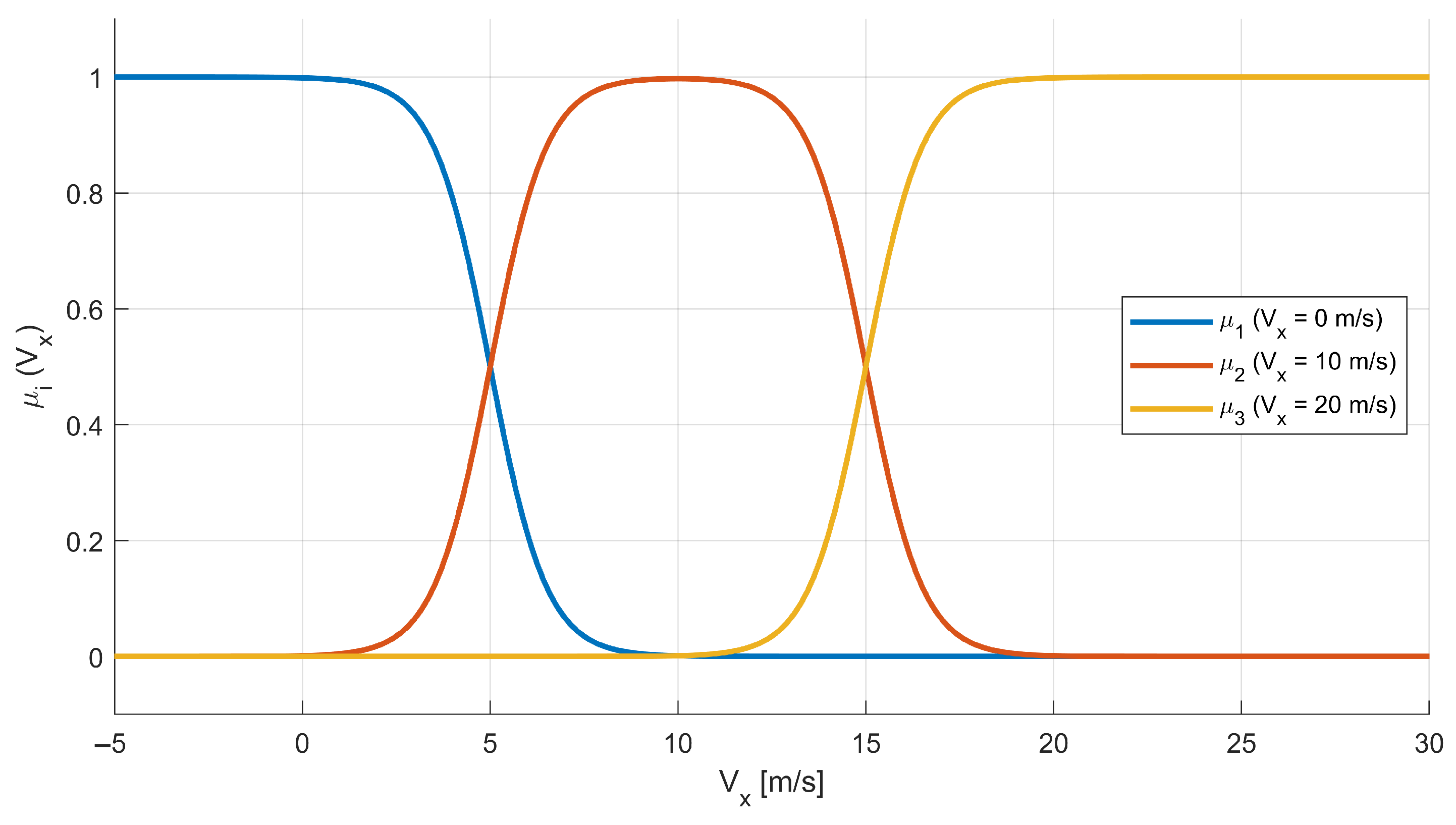
The application of the discussed approach is highly effective in controlling nonlinear systems. It allows for the approximation of the nonlinear dynamics of the analyzed object with multiple linear local models, developed, for example, from identification experiments. This approach can be widely used for controlling flying objects whose dynamics strongly depend, among other factors, on altitude and forward flight speed. The presented algorithm utilizes three separate regulators, whose outputs are combined using Formula (21), where weights in one-dimensional reasoning are computed directly from membership function values designed for this application. For the presented control system, membership functions were described as normalized Gaussian functions (22), where for the entire domain of the proposed membership functions, the condition is satisfied that the sum of all these functions is equal to one (23).
μ i ( V x ) = exp V x V x i r e f 2 2 σ i 2
where
  • V x is the measured forward flight velocity;
  • V x i r e f is the reference forward flight velocity, corresponding to the center of each membership function;
  • σ i is the standard deviation of each membership function.
In order to properly compute the output signals from the fuzzy system, it is necessary to provide the condition, where weights are normalized and their sum is equal to one in the whole domain. The condition is represented by the equation below: (23).
i = 1 N μ μ i ( V x ) = 1
Assumed membership functions μ i ( V x ) are presented in Figure 3. The centers of the membership functions are, respectively, 0 , 10 , and 20 m s . The standard deviation of each membership function is 10 m s .
In real flight conditions, each local MPC regulator—derived from a local linear model—computes its control action based on the current state of the rotorcraft. Each local control output is then weighted by its corresponding membership function, and the global control signal is obtained as a weighted sum of all local controller outputs, ensuring smooth blending between operating regions.
To guarantee the stability of the fuzzy control system, a necessary condition is that each local control loop is stable on its own. Moreover, a sufficient condition for the asymptotic stability of a Takagi–Sugeno fuzzy system was established by Tanaka and Sano [35]. It stats that in order to guarantee stability of a fuzzy system, there should be found a positive definite matrix P that satisfies the inequality presented below in (24):
D i T P D i P < 0
where D i is a state matrix for a closed-loop control system under the i-th rule. For static state-feedback regulators, defined by Equation (25), the corresponding D i closed-loop matrix can expressed by Equation (26).
u = K x
D i = A i + B i K i
where
  • A i R m × m is the state matrix of the i-th local model;
  • B i R m × n is the control matrix of the i-rule model;
  • K i R n × m is the corresponding state-feedback gain.
However, when using MPC, the control law becomes time-varying, so the classical criterion proposed by Tanaka and Sano [35] no longer directly applies. For our MPC-based fuzzy control, stability must instead be established using more general Lyapunov-based methods that support time-varying controllers. This remains a notable limitation of traditional LMI-based stability criteria, and a promising direction for future research.

3.3. Set of Fuzzy Rules

In the presented research, each of the fuzzy rules from the local regulators can be expressed as follows:
Rule 1 : If V x = 0 m / s , then u 1 ( k ) = u 0 , 1 + Δ U 1 1 : n
Rule 2 : If V x = 10 m / s , then u 2 ( k ) = u 0 , 2 + Δ U 2 1 : n
Rule 3 : If V x = 20 m / s , then u 3 ( k ) = u 0 , 3 + Δ U 3 1 : n
Each control increment vector Δ U i (for i = 1 , 2 , 3 ) is computed as the solution to the local MPC optimization problem:
Δ U i = R ¯ i + Z i Q ¯ i Z i 1 Z i Q ¯ i r ¯ p W i x ( k )
where
  • u 0 , i is the control input at the operating point associated with rule i;
  • x ( k ) is the current state vector;
  • r ¯ p is the extended reference trajectory vector over the prediction horizon;
  • W i , Z i are the state and input prediction matrices for local model i;
  • Q ¯ i , R ¯ i are the block-diagonal weighting matrices for the state and input errors.
Since Δ U i contains the full sequence of future control increments, only the first n elements are used to compute the current control input for each local regulator.
Finally, the global control signal is obtained by aggregating the local control outputs using fuzzy membership weights μ i ( V x ) corresponding to each operating point:
u ( k ) = i = 1 3 μ i ( V x ) · u i ( k )
where μ i ( V x ) [ 0 , 1 ] and i = 1 3 μ i ( V x ) = 1 .

4. System Validation

In order to evaluate the efficiency of the presented control systems, several test cases were prepared. The rest of the paper aims to demonstrate that the implementation of the Parallel Distributed Compensation approach can lead to achieving more satisfying results than using a single linear MPC controller.
The testing platform was built using the FLIGHTLAB software to precisely simulate the dynamics of the ARCHER rotorcraft and the MATLAB/SIMULINK platform to implement the proposed control system. The communication between the two processes is achieved using the TCP internet protocol, where data calculated by FLIGHTLAB and SIMULINK is transferred in predefined buffers. The integration of these two platforms enables conducting detailed simulation tests of the designed control system performance. A scheme describing platform integration is presented in Figure 4.
During the simulation experiment, the response of the controlled system was computed using a fixed-step fourth-order Runge–Kutta method. The integration step size of the helicopter dynamics model in the FLIGHTLAB environment was set to 8.333 × 10 4 s. The sampling frequency of the control signal generated by the automatic flight control system was 50 Hz. No wind effects or any other atmospheric disturbances were considered in any of the test scenarios.
The simulation scenarios, comparing two different approaches, are divided as follows:
  • Case 1: The helicopter maintains its initial altitude while changing its forward flight velocity, respectively, by 2, 6, and 10 m s . The total simulation time was 12 s.
  • Case 2: The helicopter follows a predefined flight path that includes
    A step change in forward flight velocity V x at the first second to 6 m s .
    At the 5th second, following the predefined position on the Y-axis of the reference coordinate system while maintaining a forward flight velocity pf V x = 6 m s and initial altitude of Z = 3.43 m. The function describing the predefined trajectory on the Y-axis is presented below (32). This corresponds to the sinusoidal change of position on the Y-axis, where the amplitude is 8.9 m and the oscillation period T = 9 s.
    After 18 s of performing a slalom flight, the rotorcraft returns to forward flight in the initial direction.
    Y r e f ( t ) = 8.9 sin 2 π 9 t π 9 [ m ]
The total simulation time was 30 s.
The resulting function, described by Equation (32), was determined in order to check the helicopter’s performance for a slalom maneuver defined in the ADS-33-PRF Design Standard Performance Specification, where handling qualities for military rotorcraft are defined [37]. Since ADS-33-PRF refers to large-helicopter dynamics, reference trajectories for testing aerial vehicle performance described in this specification are improper for testing the agility of small unmanned rotorcraft.
In order to preserve dynamic similitude for ARCHER’s performance testing, the slalom trajectory defined in ADS-33-PRF was scaled in order to keep the same Froude number [38]. The formula for this similitude number is presented below in (33), and for its physical interpretation, it is the ratio between inertia forces and gravitational forces in the airflow. It is assumed that the required distances traveled by the helicopters are scaled by the characteristic linear dimension of the rotorcraft, which in this case are the diameters of the main rotors.
F r = V g L
where
  • V is the airflow velocity [ m s ] .
  • g is the gravitational acceleration [ m s 2 ] .
  • L is the reference linear dimension [ m ] .
In the presented approach, it is assumed that large helicopters referred to in the ADS-33-PRF specification use main rotors with a diameter D 10 m.
The initial conditions for each test case correspond to hovering at an altitude where the landing gear of the helicopter is located 10 feet above the ground. The initial conditions are described by Formula (34).
x 0 = [ X 0 , Y 0 , Z 0 , Φ 0 , Θ 0 , Ψ 0 , V x 0 , V y 0 , V z 0 , P 0 , Q 0 , R 0 ] T
where
X 0 Y 0 Z 0 = 0 0 3.43 [ m ] , Φ 0 Θ 0 Ψ 0 = 0.0698 0.0087 0 [ rad ]
V x 0 V y 0 V z 0 = 0 0 0 [ m / s ] , P 0 Q 0 R 0 = 0 0 0 [ rad / s ]
The presented initial conditions were obtained from trim analysis, which resulted in the calculation of pitch and roll angles sufficient to preserve equilibrium for the described helicopter.

Results

In Case 1, the rotorcraft successfully increased its forward flight velocity and achieved approximately 2 m s , 6 m s , and 10 m s , which is presented in Figure 5. These forward flight velocity V x changes were simulated using a linear MPC controller and combining three separate MPC controllers using the Takagi–Sugeno inference algorithm. As the control input increases, the differences between the two systems become more pronounced. For a step change in V x r e f = 2 m s , the response characteristics of the linear MPC controller and the PDC-based controller appear nearly identical at first glance. However, as the reference flight speed increases, the linear MPC controller exhibits progressively greater overshoot, whereas the PDC controller produces a smoother response with almost no overshoot. This can be attributed to the increasing contribution of control signals derived from models linearized at higher flight speeds in the PDC approach, which more accurately approximate the helicopter dynamics compared to the model linearized for hover conditions.
In order to provide a quantitative analysis of the results, the overshoot values and the integrals of absolute errors (IAE) for the linear MPC and PDC controllers were calculated. The overshoot is defined by Equation (37), and the integral of absolute error is given in (38).
O S = v m a x v r e f v r e f · 100 %
where:
  • O S is the overshoot value expressed as a percentage.
  • v m a x is the maximum observed forward flight velocity.
  • v r e f is the reference forward flight velocity.
I A E = 0 T | v r e f v ( t ) | d t
where:
  • I A E is the integral of absolute error.
  • T is the total simulation duration.
  • v is the measured forward flight velocity at time t.
The results of the analysis are presented in Table 2, Table 3 and Table 4. For the classical MPC controller, the overshoot expressed as a percentage increases with the amplitude of the reference signal. In contrast, for the PDC controller, the overshoot decreases as the reference forward flight velocity increases.
When analyzing the absolute differences between the maximum measured velocity and the reference velocity, the MPC controller shows increasing deviations with higher reference velocities, reaching a maximum of 1.459 m s for V r e f = 10 m s . The PDC controller, however, maintains a relatively constant deviation across all reference values.
With respect to IAE values, the differences between the MPC and PDC controllers are marginal. The most significant discrepancy is observed for the step response with V r e f = 2 m s , where the difference in IAE ( Δ I A E ) is only 0.098 m s , which is negligible from a control performance perspective.
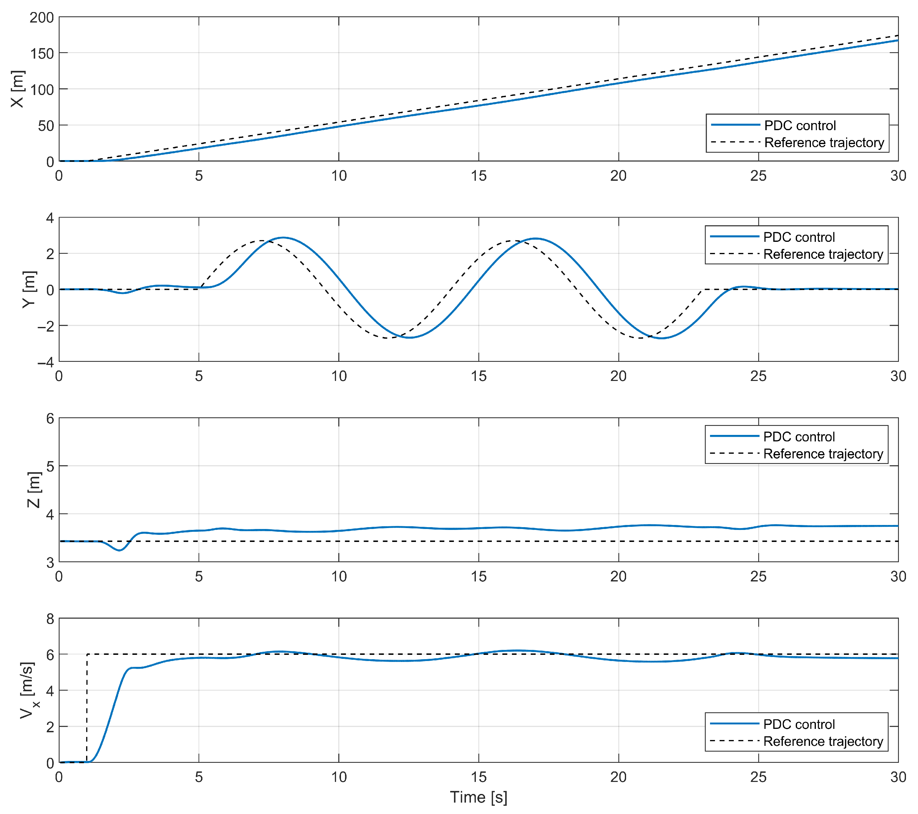
In the second test case, the performance of the regulator designed using the PDC approach was tested for a slalom flight. The reference trajectory, defined for large rotorcraft presented in the ADS-33-PRF design standard, is presented in Figure 6. The trajectory of the ARCHER flight that was performed compared to the reference signal is pictured in Figure 7. The control signals calculated in the second case are shown in Figure 8. The simulation results of the presented case with respect to time are presented in Figure 9.
In the second case, the helicopter achieved satisfactory accuracy and followed a predefined trajectory. In its initial phase of the flight, the helicopter increased its forward flight velocity to V x = 6 m s without introducing overshoot and after time t = 5 started changing its Y-axis position with time delay τ 0.8 s. Changing the Y-axis position and maintaining forward flight introduced steady state error for controlling the flight altitude, e Z 0.2 m, which is a negligibly small value.

5. Conclusions

Designing automatic flight control systems for an unmanned rotorcraft using Parallel Distributed Compensation can be an efficient way to ensure desired performance in different states of flight. The presented research shows that a Takagi–Sugeno inference mechanism, based on varying forward-flight velocity V x , helps to reduce overshoots of the measured position and linear velocity signals while accelerating.
Possible ways to ensure better handling qualities and to expand the possible range of environmental conditions in which rotorcraft can operate include, for example, the following:
  • Increase the number of “local” control laws in the PDC architecture.
  • Increase the dimensionality of input data for the Takagi–Sugeno inference mechanism, where local models can be linearized with respect to forward flight velocity and flight altitude.

Author Contributions

Conceptualization, Ł.K.; Methodology, Ł.K. and S.T.; Software, Ł.K. and S.T.; Validation, S.T.; Resources, S.T.; Visualization, Ł.K.; Supervision, S.T. All authors have read and agreed to the published version of the manuscript.

Funding

This research received no external funding.

Institutional Review Board Statement

Not applicable.

Informed Consent Statement

Not applicable.

Data Availability Statement

The raw data supporting the conclusions of this article will be made available by the authors on request.

Conflicts of Interest

The authors declare no conflicts of interest.

References

  1. Chu, Y.; Ho, C.; Lee, Y.; Li, B. Development of a Solar-Powered Unmanned Aerial Vehicle for Extended Flight Endurance. Drones 2021, 5, 44. [Google Scholar] [CrossRef]
  2. Croon, G.; Groen, M.; De Wagter, C.; Remes, B.; Ruijsink, R.; Oudheusden, B. Design, aerodynamics and autonomy of the DelFly. Bioinspiration Biomim. 2012, 7, 025003. [Google Scholar] [CrossRef]
  3. Padfield, G.D. Modelling Helicopter Flight Dynamics: Building a Simulation Model. In Helicopter Flight Dynamics; John Wiley & Sons, Ltd.: Hoboken, NJ, USA, 2007; Chapter 3; pp. 87–185. [Google Scholar]
  4. Johnson, W. Model for Vortex Ring State Influence on Rotorcraft Flight Dynamics. Ames Research Center; Mofett Field, California 2005. Available online: https://api.semanticscholar.org/CorpusID:18712216 (accessed on 17 March 2025).
  5. Faust, J.; Jung, Y.S.; Baeder, J.; Bauknecht, A.; Rauleder, J. Interactional Aerodynamic Analysis of an Asymmetric Lift-Offset Compound Helicopter in Forward Flight. J. Am. Helicopter Soc. 2021, 66, 1–17. [Google Scholar] [CrossRef]
  6. Matus-Vargas, A.; Rodriguez-Gomez, G.; Martinez-Carranza, J. Ground effect on rotorcraft unmanned aerial vehicles: A review. Intell. Serv. Robot. 2021, 14, 99–118. [Google Scholar] [CrossRef]
  7. Van Hoydonck, W.; Haverdings, H.; Pavel, M. A review of rotorcraft wake modeling methods for flight dynamics applications. In Proceedings of the 35th European Rotorcraft Forum 2009, Hamburg, Germany, 22–25 September 2009; Volume 1, pp. 27–53. [Google Scholar]
  8. Shim, D.; Kim, H.J.; Sastry, S. Control system design for rotorcraft-based unmanned aerial vehicles using time-domain system identification. In Proceedings of the 2000 IEEE International Conference on Control Applications, Anchorage, AK, USA, 27 September 2000; pp. 808–813. [Google Scholar]
  9. Gadewadikar, J.; Chen, B.; Subbarao, K. Structured H Command and Control-Loop Design for Unmanned Helicopters. J. Guid. Control. Dyn. 2008, 31, 1093–1102. [Google Scholar] [CrossRef]
  10. Dul, F.; Lichota, P.; Rusowicz, A. Generalized Linear Quadratic Control for a Full Tracking Problem in Aviation. Sensors 2020, 20, 2955. [Google Scholar] [CrossRef] [PubMed]
  11. Topczewski, S.; Narkiewicz, J.; Bibik, P. Helicopter Control During Landing on a Moving Confined Platform. IEEE Access 2020, 8, 107315–107325. [Google Scholar] [CrossRef]
  12. Topczewski, S.; Bibik, P. LQR and LQG control of the helicopter during landing on the ship deck. Aircr. Eng. Aerosp. Technol. 2023, 95, 1344–1352. [Google Scholar] [CrossRef]
  13. Chen, Y.; Wang, X.; Lu, G.; Zhong, Y. Modeling and LQR control of small unmanned helicopter. In Proceedings of the 32nd Chinese Control Conference, Hefei, China, 22–24 August 2020; pp. 4301–4305. [Google Scholar]
  14. Jan, S.S.; Lin, Y.H. Integrated Flight Path Planning System and Flight Control System for Unmanned Helicopters. Sensors 2011, 11, 7502–7529. [Google Scholar] [CrossRef]
  15. Kadmiry, B.; Driankov, D. Fuzzy Control of an Autonomous Helicopter. In Proceedings of the IFSA World Congress and 20th NAFIPS International Conference, Vancouver, BC, Canada, 25–28 July 2001. [Google Scholar]
  16. Lin, K.; Li, D.; Li, Y.; Chen, S.; Wu, X. FHCPL: An Intelligent Fixed-Horizon Constrained Policy Learning System for Risk-Sensitive Industrial Scenario. IEEE Trans. Ind. Inform. 2024, 20, 5794–5804. [Google Scholar] [CrossRef]
  17. Lin, K.; Li, Y.; Chen, S.; Li, D.; Wu, X. Motion Planner with Fixed-Horizon Constrained Reinforcement Learning for Complex Autonomous Driving Scenarios. IEEE Trans. Intell. Veh. 2024, 9, 1577–1588. [Google Scholar] [CrossRef]
  18. Liu, B.; Cai, Y.; Li, D.; Lin, K.; Xu, G. A Hybrid ARO Algorithm and Key Point Retention Strategy Trajectory Optimization for UAV Path Planning. Drones 2024, 8, 644. [Google Scholar] [CrossRef]
  19. Lin, K.; Li, D.; Li, Y.; Chen, S.; Liu, Q.; Gao, J.; Jin, Y.; Gong, L. TAG: Teacher-Advice Mechanism With Gaussian Process for Reinforcement Learning. IEEE Trans. Neural Netw. Learn. Syst. 2024, 35, 12419–12433. [Google Scholar] [CrossRef]
  20. Lin, K.; Li, Y.; Liu, Q.; Li, D.; Shi, X.; Chen, S. Almost surely safe exploration and exploitation for deep reinforcement learning with state safety estimation. Inf. Sci. 2024, 662, 120261. [Google Scholar] [CrossRef]
  21. Gong, X. Model Predictive Control for an Unmanned Helicopter. In Proceedings of the 2019 IEEE International Conference on Unmanned Systems (ICUS), Beijing, China, 17–19 October 2019; pp. 361–366. [Google Scholar]
  22. Alexis, K.; Papachristos, C.; Siegwart, R.; Tzes, A. Robust Model Predictive Flight Control of Unmanned Rotorcrafts. J. Intell. Robot. Syst. 2015, 81, 443–469. [Google Scholar] [CrossRef]
  23. Lindqvist, B.; Mansouri, S.S.; Agha-mohammadi, A.a.; Nikolakopoulos, G. Nonlinear MPC for Collision Avoidance and Control of UAVs With Dynamic Obstacles. IEEE Robot. Autom. Lett. 2020, 5, 6001–6008. [Google Scholar] [CrossRef]
  24. Stella, L.; Themelis, A.; Sopasakis, P.; Patrinos, P. A simple and efficient algorithm for nonlinear model predictive control. In Proceedings of the 2017 IEEE 56th Annual Conference on Decision and Control (CDC), Melbourne, VIC, Australia, 12–15 December 2017; pp. 1939–1944. [Google Scholar]
  25. Li, Z.; Xue, Y.; Li, Z.; Jin, X.; Wang, P. Resilience-Oriented Asynchronous Decentralized Restoration Considering Building and E-Bus Co-Response in Electricity-Transportation Networks. IEEE Trans. Transp. Electrif. 2025, 1. [Google Scholar] [CrossRef]
  26. Ding, B.; Li, Z.; Li, Z.; Xue, Y.; Chang, X.; Su, J. Cooperative Operation for Multiagent Energy Systems Integrated With Wind, Hydrogen, and Buildings: An Asymmetric Nash Bargaining Approach. IEEE Trans. Ind. Inform. 2025, 21, 6410–6421. [Google Scholar] [CrossRef]
  27. Bedyńska, A.; Curyło, P.; Czarnota, N.; Ceniuk, M.; Grabowski, Ł.; Łukasiewicz, M.; Bibik, P. ARCHER—Autonomous Reconfigurable Compound Helicopter for Education and Research. Paper Presented at the 45th European Rotorcraft Forum, Warsaw, Poland, 17–20 September 2019. [Google Scholar]
  28. Żugaj, M.; Edawdi, M.; Iwański, G.; Topczewski, S.; Bibik, P. An Unmanned Helicopter Energy Consumption Analysis. Energies 2022, 15, 2067. [Google Scholar] [CrossRef]
  29. Abdelgawad, K.; Hassan, B.; Berssenbrügge, J.; Stöcklein, J. A Modular Architecture of an Interactive Simulation and Training Environment for Advanced Driver Assistance Systems. Int. J. Adv. Softw. 2015, 8, 247–261. [Google Scholar]
  30. Val, R.; He, C. FLIGHTLAB Modeling for Real Time Simulation Applications. Int. J. Model. Simul. Sci. Comput. 2017, 8, 1743003. [Google Scholar] [CrossRef]
  31. Peters, D.A.; He, C. Correlation of Measured Induced Velocities with a Finite-State Wake Model. J. Am. Helicopter Soc. 1991, 36, 59–70. [Google Scholar] [CrossRef]
  32. Wang, H.; Tanaka, K.; Griffin, M. Parallel distributed compensation of nonlinear systems by Takagi-Sugeno fuzzy model. In Proceedings of the 1995 IEEE International Conference on Fuzzy Systems, Yokohama, Japan, 20–24 March 1995; Volume 2, pp. 531–538. [Google Scholar]
  33. Camacho, E.F.; Bordons, C. Model Predictive Control, 2nd ed.; Springer: London, UK, 2004. [Google Scholar]
  34. Takagi, T.; Sugeno, M. Fuzzy identification of systems and its applications to modeling and control. IEEE Trans. Syst. Man Cybern. 1985, SMC-15, 116–132. [Google Scholar] [CrossRef]
  35. Tanaka, K.; Sano, M. Fuzzy stability criterion of a class of nonlinear systems. Inf. Sci. 1993, 71, 3–26. [Google Scholar] [CrossRef]
  36. Bibik, P.; Kopyt, A.; Żugaj, M. LIGHTLAB & SIMULINK—Coupling of modern simulation tools of modelling and testing of rotorcraft control systems. Inst. Aviat. Work. Wars. 2011, 219, 5–12. [Google Scholar]
  37. ADS-33E-PRF; Aeronautical Design Standard, Performance Specification, Handling Qualities Requirements for Military Rotorcraft. United States Army Aviation and Missile Command: Red Stone, AL, USA, 2000.
  38. Chang, I.K.; Ryu, B.S.; Kim, J.H.; Kim, Y.J. Stability Test Using Froude Scaling Method of Emergency Flotation System for Helicopter. J. Korean Soc. Aeronaut. Space Sci. 2015, 43, 1089–1096. [Google Scholar] [CrossRef]
Figure 1. ARCHER helicopter while hovering [28]. The rotorcraft was designed and developed at the Division of Automation and Aeronautical Systems, Warsaw University of Technology.
Applsci 15 08120 g001
Figure 2. Automatic Flight Control System scheme (Source: Authors’ own work).
Applsci 15 08120 g002
Figure 3. Membership functions μ i ( V x ) used in the proposed reasoning.
Applsci 15 08120 g003
Figure 4. SIMULINK and FLIGHTLAB integration scheme [36].
Applsci 15 08120 g004
Figure 5. Comparison of PDC approach and linear MPC controller for forward flight velocity V x increase.
Applsci 15 08120 g005
Figure 6. The 2D trajectory for slalom maneuvers proposed for military rotorcrafts based on the ADS-33-PRF design standard.
Applsci 15 08120 g006
Figure 7. The 2D trajectory obtained during the second test case.
Applsci 15 08120 g007
Figure 8. Control signals calculated during the second test case.
Applsci 15 08120 g008
Figure 9. Simulation results for the second test case.
Applsci 15 08120 g009
Table 1. Basic ARCHER characteristics.
ParameterValueUnit
Main rotor diameter1.78m
Number of main rotor blades2-
Main rotor angular velocity1500–2000RPM
Tail rotor diameter0.158m
Number of tail rotor blades2-
Tail rotor angular velocity7200RPM
Takeoff weight (TOW)8kg
Table 2. Overshoot values for Case 1 [%].
MPCPDC
V r e f = 2 m s 7.5%8.13%
V r e f = 6 m s 9.62%4.81%
V r e f = 10 m s 14.59%−0.7%
Table 3. Overshoot values for Case 1 [ m s ].
MPCPDC
V r e f = 2 m s 0.15 m s 0.163 m s
V r e f = 6 m s 0.577 m s 0.289 m s
V r e f = 10 m s 1.459 m s −0.07 m s
Table 4. IAE values for Case 1 [ m s ].
MPCPDC
V r e f = 2 m s 2.788 m s 2.886 m s
V r e f = 6 m s 8.729 m s 8.838 m s
V r e f = 10 m s 15.230 m s 15.227 m s
Disclaimer/Publisher’s Note: The statements, opinions and data contained in all publications are solely those of the individual author(s) and contributor(s) and not of MDPI and/or the editor(s). MDPI and/or the editor(s) disclaim responsibility for any injury to people or property resulting from any ideas, methods, instructions or products referred to in the content.