Article

Drag Reduction and Efficiency Enhancement in Wide-Range Electric Submersible Centrifugal Pumps via Bio-Inspired Non-Smooth Surfaces: A Combined Numerical and Experimental Study

Research Institute of Petroleum Exploration and Development, PetroChina Company Limited, Beijing 100083, China
*
Author to whom correspondence should be addressed.
Appl. Sci. 2025, 15(14), 7989; https://doi.org/10.3390/app15147989
Submission received: 20 May 2025 / Revised: 27 June 2025 / Accepted: 10 July 2025 / Published: 17 July 2025

Abstract

Featured Application

The bio-inspired dimple-structured surfaces developed in this study significantly improve the hydraulic efficiency and operational adaptability of wide-range electric submersible centrifugal pumps (ESPs). This innovation is directly applicable to offshore oilfield production systems, where ESPs are critical for high-displacement artificial lift. By expanding high-efficiency operating zones and reducing energy losses through drag reduction, the optimized pumps enable prolonged service life, lower maintenance costs, and enhanced adaptability to dynamic reservoir conditions. This technology supports sustainable offshore oil production by minimizing energy consumption and operational downtime, particularly during late-stage field development with declining productivity.

Abstract

Wide-range electric submersible centrifugal pumps (ESPs) are critical for offshore oilfields but suffer from narrow high-efficiency ranges and frictional losses under dynamic reservoir conditions. This study introduces bio-inspired dimple-type non-smooth surfaces on impeller blades to enhance hydraulic performance. A combined numerical-experimental approach was employed: a 3D CFD model with the k-ω turbulence model analyzed oil–water flow (1:9 ratio) to identify optimal dimple placement, while parametric studies tested diameters (0.6–1.2 mm). Experimental validation used 3D-printed prototypes. Results revealed that dimples on the pressure surface trailing edge reduced boundary layer separation, achieving a 12.98% head gain and 8.55% efficiency improvement at 150 m3/d in simulations, with experimental tests showing an 11.5% head increase and 4.6% efficiency gain at 130 m3/d. The optimal dimple diameter (0.9 mm, 2% of blade chord) balanced performance and manufacturability, demonstrating that bio-inspired surfaces improve ESP efficiency. This work provides practical guidelines for deploying drag reduction technologies in petroleum engineering, with a future focus on wear resistance in abrasive flows.

1. Introduction

Electrical submersible pumps (ESPs) have become the core artificial lift equipment in offshore oilfield development due to their advantages of high displacement, superior efficiency, and automation capabilities [1]. Statistical data indicate that ESP systems account for 92% of production wells in China’s offshore oilfields, with 98% utilizing ESP lifting technology [2]. However, conventional ESP systems face two critical technical limitations: First, their narrow, high-efficiency operating ranges struggle to adapt to dynamic reservoir variations, causing frequent deviations from design conditions that lead to impeller wear and efficiency degradation [3]. Second, fixed-parameter pump designs fail to match declining productivity during late-stage oilfield development, resulting in costly frequent pump replacements [4]. Wide-range ESP technology addresses these challenges by expanding high-efficiency operating zones, reducing pump configuration requirements by over 30% through dynamic adaptability, and has emerged as a key research direction for intelligent completion technologies [5,6,7,8,9].
Current optimization studies for wide-range ESP hydraulic performance primarily focus on flow channel topology optimization and variable frequency control [10,11,12]. Notably, hydraulic losses caused by rotational effects in impeller-diffuser systems and surface friction account for 40–50% of total energy losses [13], positioning surface drag reduction as a critical breakthrough for efficiency enhancement. Bio-inspired non-smooth surface structures (e.g., dimples, riblets) have demonstrated significant drag reduction benefits across hydrodynamics applications, including ship resistance reduction [14,15], underwater robotics [16], high-speed trains [17], and petroleum engineering [18,19].
Recent advances reveal promising applications of bio-inspired non-smooth structures in centrifugal pump optimization: Lin Xucheng et al. [20] designed mushroom-like microtextured blades mimicking sea skater exoskeletons, reducing cavitation bubble volume by 54.75% during incipient stages. Gan Guanghua et al. [21] achieved a 2.5% head improvement using crab shell-inspired microsphere structures. Mu Jiegang et al. [22] demonstrated a 5.8% torque reduction via dimple-type non-smooth units on blade pressure surfaces through numerical simulations. A comparative study by Dai Dongshun [23] revealed superior drag reduction performance of dimpled surfaces over V-grooves, particularly under high-flow conditions. Parametric analyses by Li Kaijie [24] identified nonlinear relationships between dimple size-spacing parameters and drag reduction effectiveness, emphasizing the need for multi-objective optimization. Dai Cui et al. [25] reported a 23% efficiency gain by strategically placing non-smooth structures in high-shear-stress regions. Peng Qian et al. [26] confirmed dimple structures as optimal among three typical non-smooth surfaces (dimples, protrusions, and wavy textures) through friction coefficient calculations.
This study focuses on optimizing dimple-type non-smooth structures for wide-range ESPs under low-flow and complex media conditions, incorporating manufacturing feasibility constraints. A CFD-based multiphysics-coupled model systematically investigates the influence mechanisms of non-smooth array topology and structural parameters on flow characteristics, validated through full-scale prototype testing across multiple operating conditions. The findings provide theoretical foundations for hydraulic performance optimization of wide-range ESPs and advance the engineering application of bio-inspired drag reduction technologies in intelligent oil production systems.

2. Materials and Methods

This study employs a two-stage investigation protocol. Initially, computational fluid dynamics (CFD) simulations were conducted to optimize the spatial distribution of dimpled non-smooth units on the impeller surface. Subsequently, a physical prototype was fabricated based on the simulation results, and comparative experiments were systematically performed to evaluate the hydrodynamic optimization mechanisms by quantifying performance differentials in head and efficiency between baseline and optimized configurations.

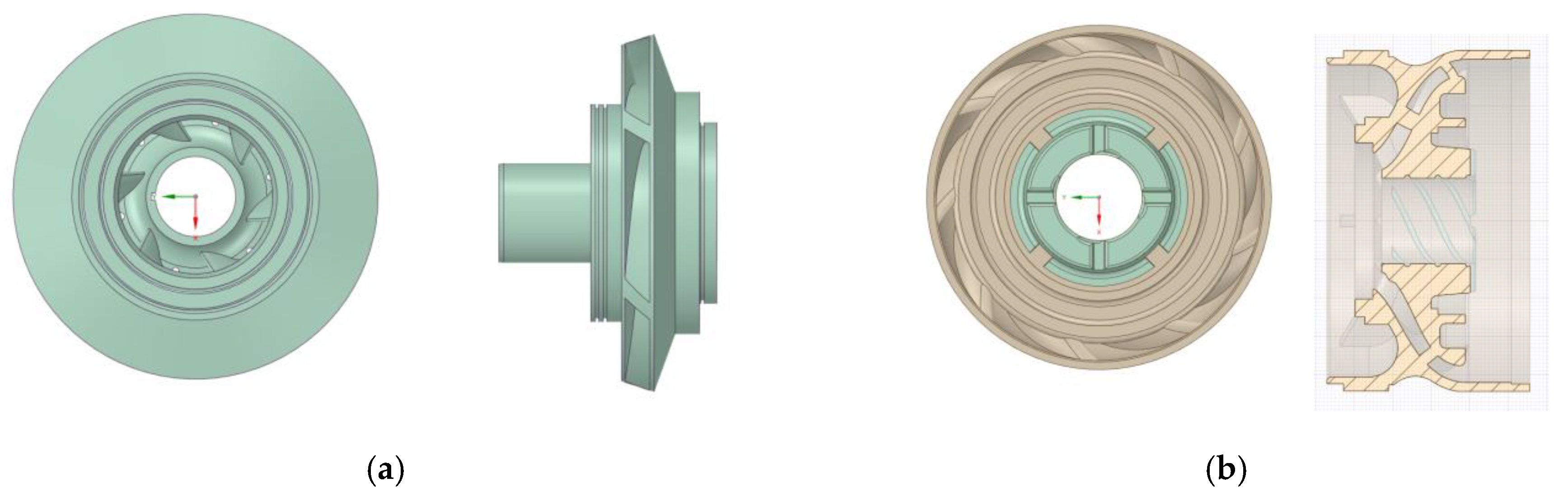
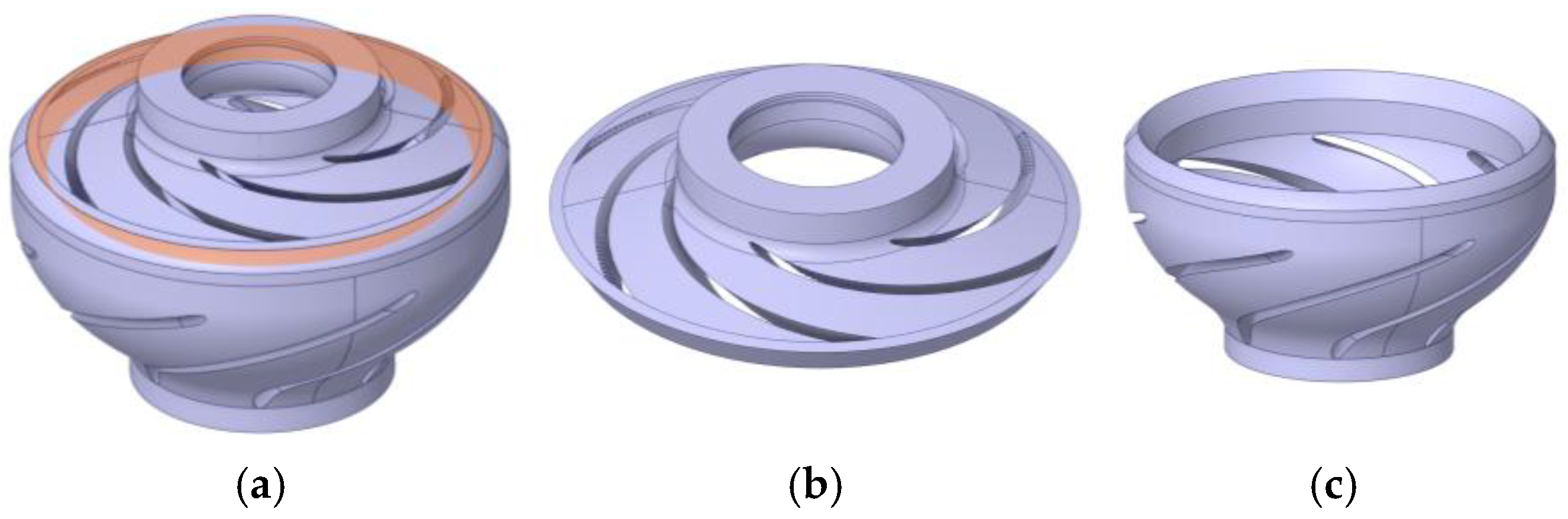
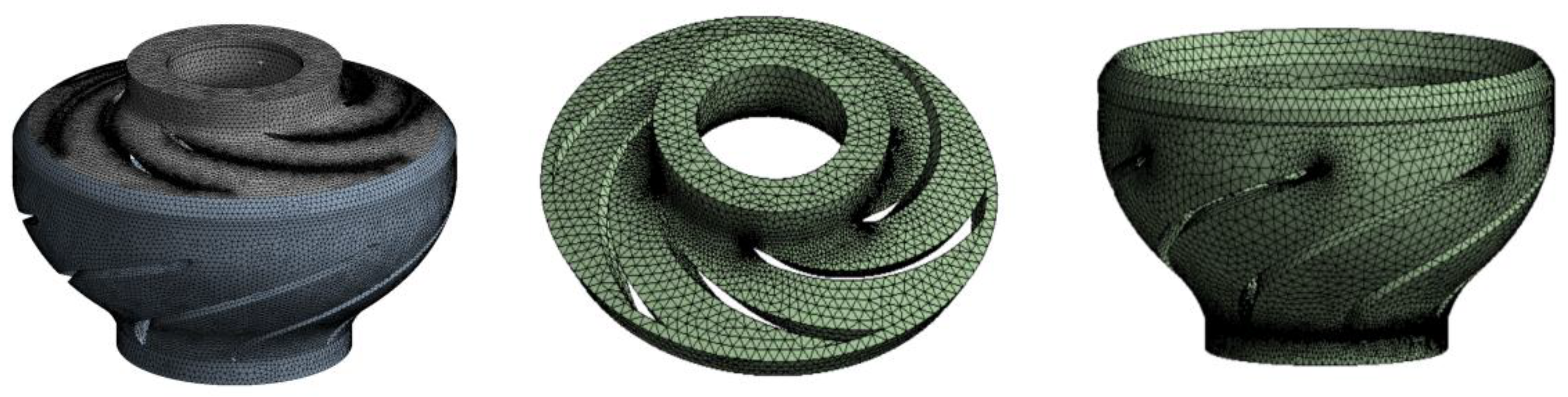
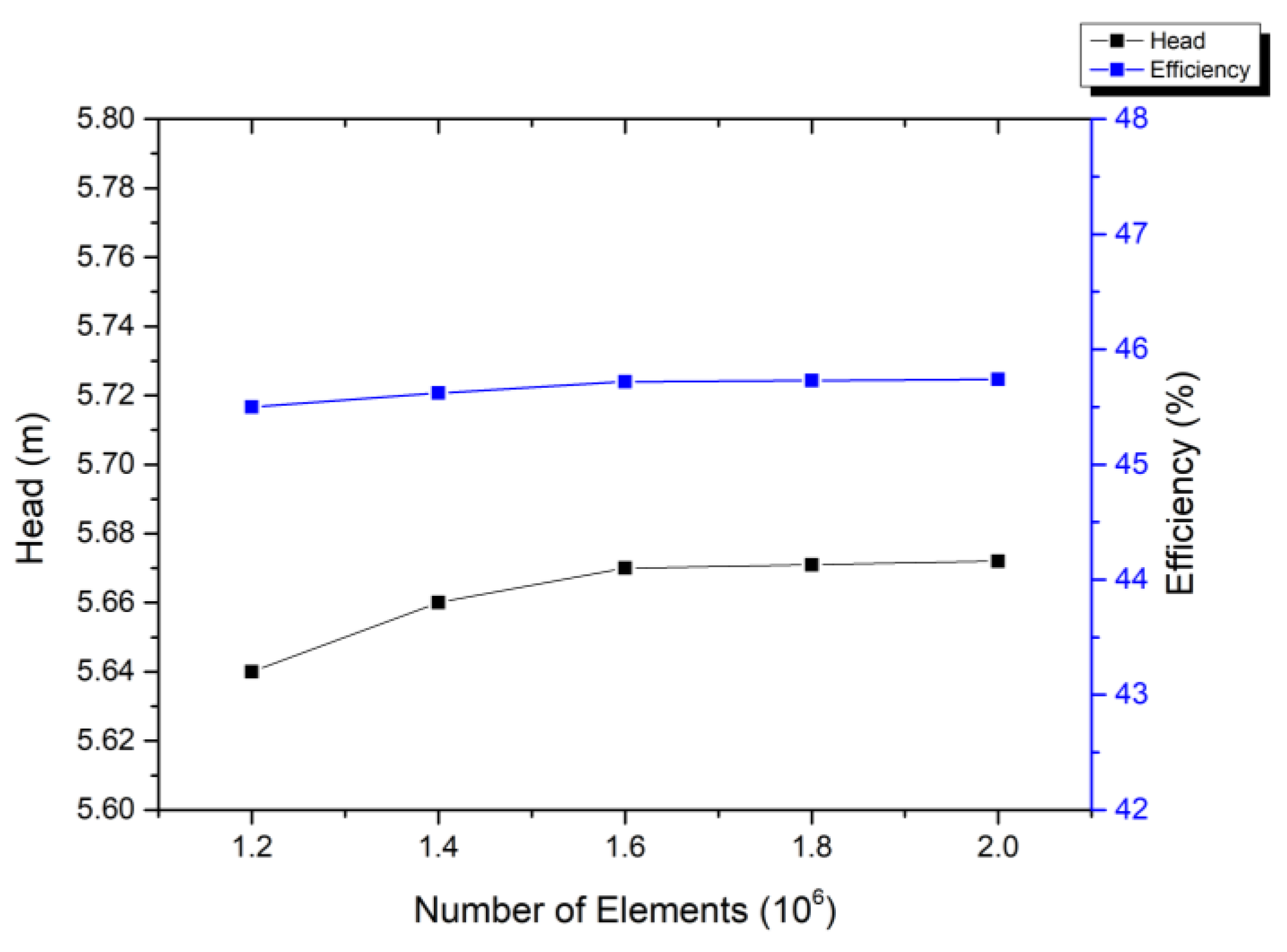
2.1. Numerical Model

The geometric model of the wide-range centrifugal pump impeller used in this study is illustrated in Figure 1. Key design parameters include a single-stage head ≥4.5 m, a flow rate range of 0–200 m3/d, a rated rotational speed of 3000 r/min, an impeller outer diameter of 72.85 mm (matching a guide vane outer diameter of 88.9 mm), a shaft diameter of 17.4 mm, an outlet width of 6.29 mm, 6 blades, and a minimum blade thickness of 3 mm at the outlet. The computational domain, constructed from the 3D solid model, was divided into rotating impeller and stationary guide vane subdomains (Figure 2), coupled through interface boundaries for fluid–field interaction.
The numerical simulation was conducted using the commercial CFD software ANSYS Fluent 2022 R1. The governing equations encompass mass conservation, momentum conservation, and energy conservation. Given that this study focuses on the hydraulic performance of ESP with stable medium temperature, thermal diffusion and conduction effects were neglected during computation. The fluid model was simplified to an adiabatic, incompressible, viscous Newtonian fluid.
Continuity Equation (Mass Conservation Equation):
u x + v y + w z = 0
where u, v, and w represent the velocity components in the x, y, and z directions, respectively.
Momentum Equations (Navier–Stokes Equations):
u t + u u x + v u y + w u z = F x 1 ρ p x + μ ρ 2 u v t + u v x + v v y + w v z = F y 1 ρ p y + μ ρ 2 v w t + u w x + v w y + w w z = F z 1 ρ p z + μ ρ 2 w
where ρ denotes the density, p denotes the pressure on the fluid element, μ represents the dynamic viscosity, Fx, Fy, and Fz represent the body forces acting on the element. When gravity is the sole body force acting numerically downward along the z-axis, Fx = 0, Fy = 0, Fz = ρg.
Given the focus on near-wall flow characteristics affecting frictional resistance, the standard k-ω turbulence model was selected for numerical simulation. This model demonstrates high accuracy under complex pressure gradients and effectively resolves near-wall flow features and boundary layer separation. Turbulent viscosity was calculated using the correlation equations for turbulent kinetic energy k and specific dissipation rate ω (Equation (3)), where the transport equations for k (Equation (4)) and ω (Equation (5)) characterize turbulent energy distribution and dissipation, respectively:
μ t = ρ k ω
ρ k t + ρ u k x + ρ v k y + ρ w k z = x μ + μ t σ k k x + y μ + μ t σ k k y + z μ + μ t σ k k z + μ t C μ ρ k ω
ρ ω t + ρ u ω x + ρ v ω y + ρ w ω z = x μ + μ t σ k ω x + y μ + μ t σ k ω y + z μ + μ t σ k ω z + γ ρ Φ β ρ ω 2
where μt represents the turbulent viscosity coefficient, k represents turbulent kinetic energy, ω represents specific dissipation rate, μ represents the dynamic viscosity coefficient, ρ represents fluid density, σ k = 2.0, σ ω = 2.0, γ = 0.556, β′ = 0.075 [27].
Turbulent flow, characterized by stochastic perturbations and pulsating characteristics, exhibits complex irregularities distinct from the ordered motion of laminar flow. This inherent complexity precludes rigorous mathematical derivation of turbulent phenomena. In engineering practice, fluid motion is therefore represented by time-averaged mean values over infinitesimal intervals. Steady-state simulations consequently employ Reynolds-averaged treatment—assuming fully developed flow and statistically steady conditions—which simplifies governing equations while aligning with the research objective of analyzing fixed operating points in engineering optimization.
For centrifugal pump steady-state simulations, rotor–stator interface selection is critical due to its direct impact on computational accuracy and efficiency. This study adopts the Multiple Reference Frame (MRF) method (also known as the frozen rotor approach) to model the interface between impeller and volute core regions. Compared to alternative methods, this approach offers significantly reduced computational expense.
All pump walls were assigned no-slip and no-penetration boundary conditions, ensuring zero mass, momentum, and energy fluxes across the solid boundaries. The axis of rotation, which corresponds to the spin axis of the impeller fluid domain, is aligned with the impeller centerline; consequently, it exhibits zero relative velocity within the rotating reference frame. Pressure-velocity coupling was resolved using the coupled pressure-based SIMPLE algorithm [28]. For spatial discretization, convective terms employed the first-order upwind scheme to ensure stability under high-Reynolds-number flow conditions, while viscous terms utilized the second-order central differencing scheme, the standard approach for diffusion terms. Temporal discretization employed a steady-state implicit formulation, thereby omitting transient terms.
To address the complex curved geometry of the impeller, an unstructured tetrahedral mesh was employed for discretization using Ansys Meshing. Local grid refinement was implemented in the blade region to accurately capture the effects of geometric discontinuities on flow characteristics. The resulting mesh configuration is illustrated in Figure 3.
Figure 4 displays the monitored head and efficiency results under the design operating condition (flow rate: 100 m3/h) with varying mesh densities. The results demonstrate that upon reaching 1.6 million total elements, variations in both head and efficiency diminish significantly and stabilize. Consequently, the final computational model adopted approximately 1.6 × 10⁶ elements to effectively balance computational accuracy and efficiency.
The MRF method addressed rotor–stator interaction, with velocity inlet (Equation (6)) and constant pressure outlet boundary conditions:
v i n = Q A
where Q is flow rate and A denotes inlet area.
The working fluid was an oil–water mixture with a volumetric ratio of 1:9, and the impeller rotational speed was set to 3500 r/min. Near-wall turbulence was resolved using standard wall functions. Solution convergence was defined by residuals below 10−5. Given the study’s focus on near-wall flow control—rather than multiphase interactions—and the applicability of approximating the mixture as a homogeneous fluid under the high water-cut condition (90%), a single-phase model was adopted to achieve a compromise between computational efficiency and engineering accuracy. Multiphase flow models would be necessary for future scenarios involving gas presence or high oil-cut conditions. Specific boundary condition configurations are detailed in Table 1. This modeling framework effectively characterizes the influence mechanisms of non-smooth structures on blade surface flow dynamics.
Building upon the findings of Dai et al. [25] regarding the optimal placement of bio-inspired non-smooth structures on centrifugal pump blades, this study posits that arranging non-smooth structures in peak shear stress regions under fixed dimple unit quantities maximizes drag reduction effectiveness. To validate this hypothesis, a quantitative analysis of shear stress distribution on the impeller surface was performed through numerical simulations.
Numerical results under typical operating conditions (flow rate: 100 m3/d, oil–water volumetric ratio: 1:9) are illustrated in Figure 5. The impeller surface exhibits significant spatial heterogeneity in shear stress distribution, with pronounced stress concentration observed at the leading edge of the suction surface and the trailing edge of the pressure surface. Based on this flow field characterization, these two shear stress extremum regions were selected as optimization zones for non-smooth structures. The topological arrangement of dimple-type units is shown in Figure 6. This targeted placement strategy aims to maximize flow characteristic improvements through localized drag reduction effects.
Guided by the geometric similarity criterion established by Wang et al. [29], which asserts optimal drag reduction when the ratio of dimple diameter to blade chord length reaches 2%, the theoretically calculated optimal dimple diameter for this study’s impeller (chord length: 48.5 mm) is d = 0.97 mm. To investigate size sensitivity, three comparative parameter sets were designed: suboptimal diameter (d = 0.6 mm), near-optimal diameter (d = 0.9 mm), and supra-optimal diameter (d = 1.2 mm). These dimples were arranged in the shear stress peak regions identified in Section 3.1 (Figure 5) with circumferential spacing governed by m = n = d + 0.1 mm, where m and n denote axial and radial spacing, respectively. This configuration systematically characterizes the nonlinear relationship between dimple dimensions and flow behavior.
The pump head H is defined as follows:
H = p 2 p 1 ρ g + v 2 2 v 1 2 2 g + ( z 2 z 1 )
where p1 and p2 represent inlet and outlet pressures, v1 and v2 denote fluid velocities at corresponding cross-sections, z1 and z2 indicate pressure sensor elevations.
Pump efficiency η is expressed as follows:
η = P e P × 100 %
where the effective power Pe and shaft power P are calculated as follows:
P e = γ Q H 1000
P = α T n 9550
where γ is the fluid’s specific weight, Q is flow rate, T is torque, n is rotational speed, and α represents a correction factor [27].
Head gain (ΔH) and efficiency gain (Δη) are defined as follows:
Δ H = H 2 H 1 H 1 × 100 %
Δ η = η 2 η 1 η 1 × 100 %
H1, η1: head and efficiency of the original model (smooth surface); H2, η2: head and efficiency of the modified impeller (non-smooth surface).

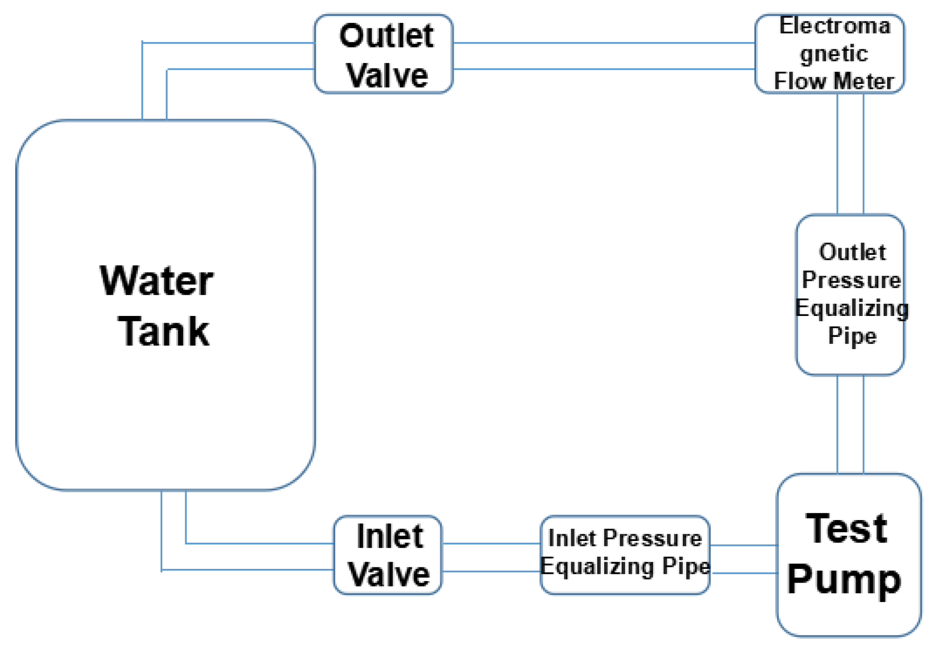
2.2. Experimental System

The prototype of the wide-range ESP and its optimized model (featuring non-smooth surface arrays on the impeller blades) were experimentally investigated in a closed-loop circulation system as illustrated in Figure 7. The optimized configuration was derived from computational simulations targeting hydraulic performance enhancement. The closed-loop test system comprises a drive motor, a test section, and a data acquisition unit. The drive motor operates at a rated speed of 3000 rpm and a rated power of 3.7 kW. The test subject is a three-stage impeller-diffuser assembly. Two groups of samples were evaluated: the baseline group with conventional smooth-surface impellers and the optimized group featuring dimple arrays (diameter: 0.9 mm) distributed on the pressure side trailing edge and suction side leading edge of the impellers. The data acquisition system includes the following:
  • Flow measurement: Electromagnetic flowmeter (accuracy: 0.5% FS).
  • Pressure measurement: Two dynamic pressure sensors (range: 0–1 MPa, accuracy: 0.1%) installed at both the inlet and outlet.
  • Speed monitoring: Optical encoder (resolution: 0.1°).
The head (H) and efficiency (η) were calculated using Equations (7) and (8), respectively. Tests were conducted across a flow rate range of 20–200 m3/d, with varying operating conditions achieved through adjustments to the valve. Each operating condition was measured three times, and the arithmetic mean was calculated. Experimental uncertainty was quantified using Type B evaluation, with head uncertainty δH and efficiency uncertainty δη calculated according to Equations (13) and (14), respectively [30].
δ H = ( 0.1 % × Δ p ) 2 + ( 0.3 % ) 2
where Δp represents the pump differential pressure (discharge minus suction pressure), 0.1% represents the pressure transducer accuracy, and 0.3% accounts for elevation measurement uncertainty.
δ η = δ H 2 + ( 0.5 % ) 2
where 0.5% represents the flowmeter precision.

3. Results

This section systematically elucidates the performance optimization effects of non-smooth structures on ESPs across a wide operating range. First, parametric simulations (Section 3.1) reveal quantitative relationships between pit dimensions/locations and performance metrics. Subsequently, experimental data from additively manufactured prototypes (Section 3.2) validate the numerical model’s reliability while providing in-depth analysis of key performance enhancement mechanisms.

3.1. Simulation

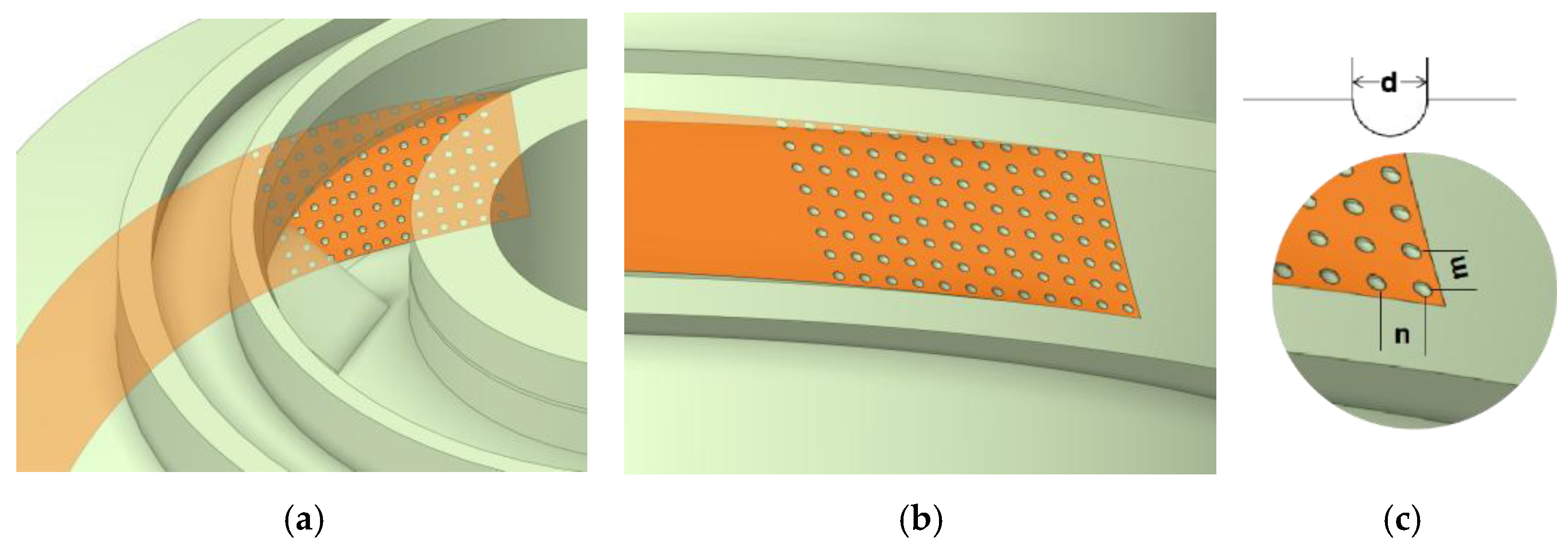
3.1.1. Design of Non-Smooth Structure Parameters

CFD simulations were conducted across a flow rate range of 50–150 m3/d for the three dimple configurations (Figure 8). Key findings include the following:
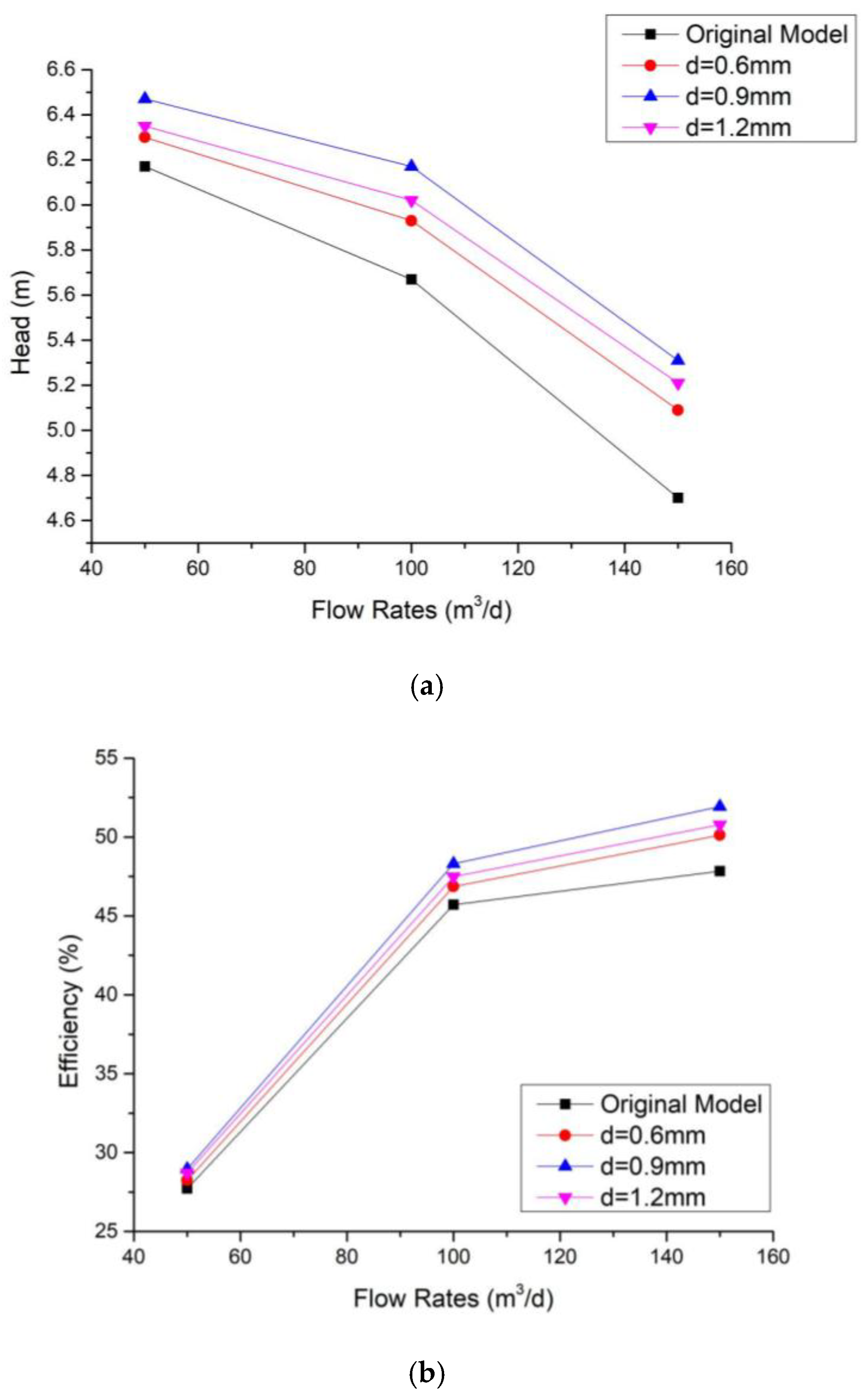
  • Flow-Dependent Head Enhancement: Maximum head gain of 12.98% occurred at 150 m3/d, representing a 515% increase compared to the 2.11% improvement at 50 m3/d.
  • Consistent Efficiency Trends: Efficiency gains mirrored head improvements, with 8.55% enhancement at 150 m3/d versus 1.88% at 50 m3/d.
  • Nonlinear Size-Performance Relationship: The d = 0.9 mm configuration achieved synchronized optimization at 150 m3/d, delivering 12.98% head gain and 8.55% efficiency improvement over the baseline, validating the engineering applicability of the theoretical optimal diameter.

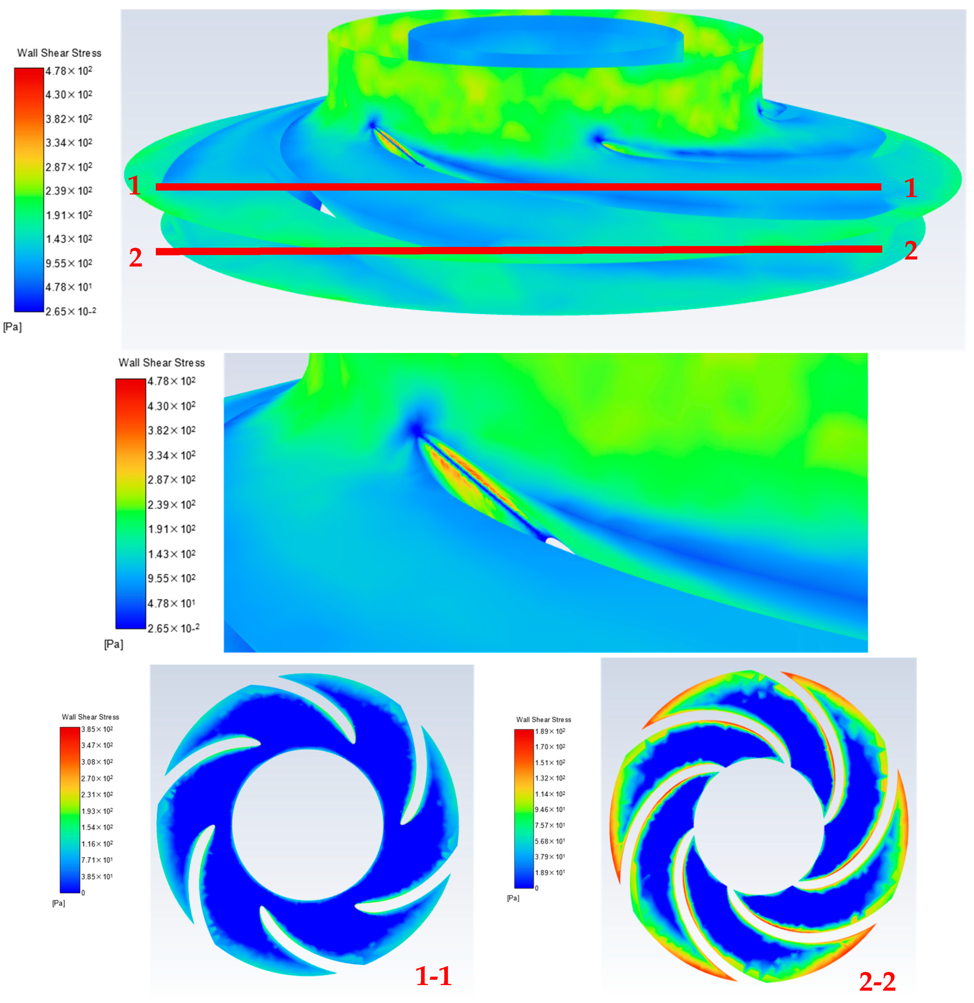
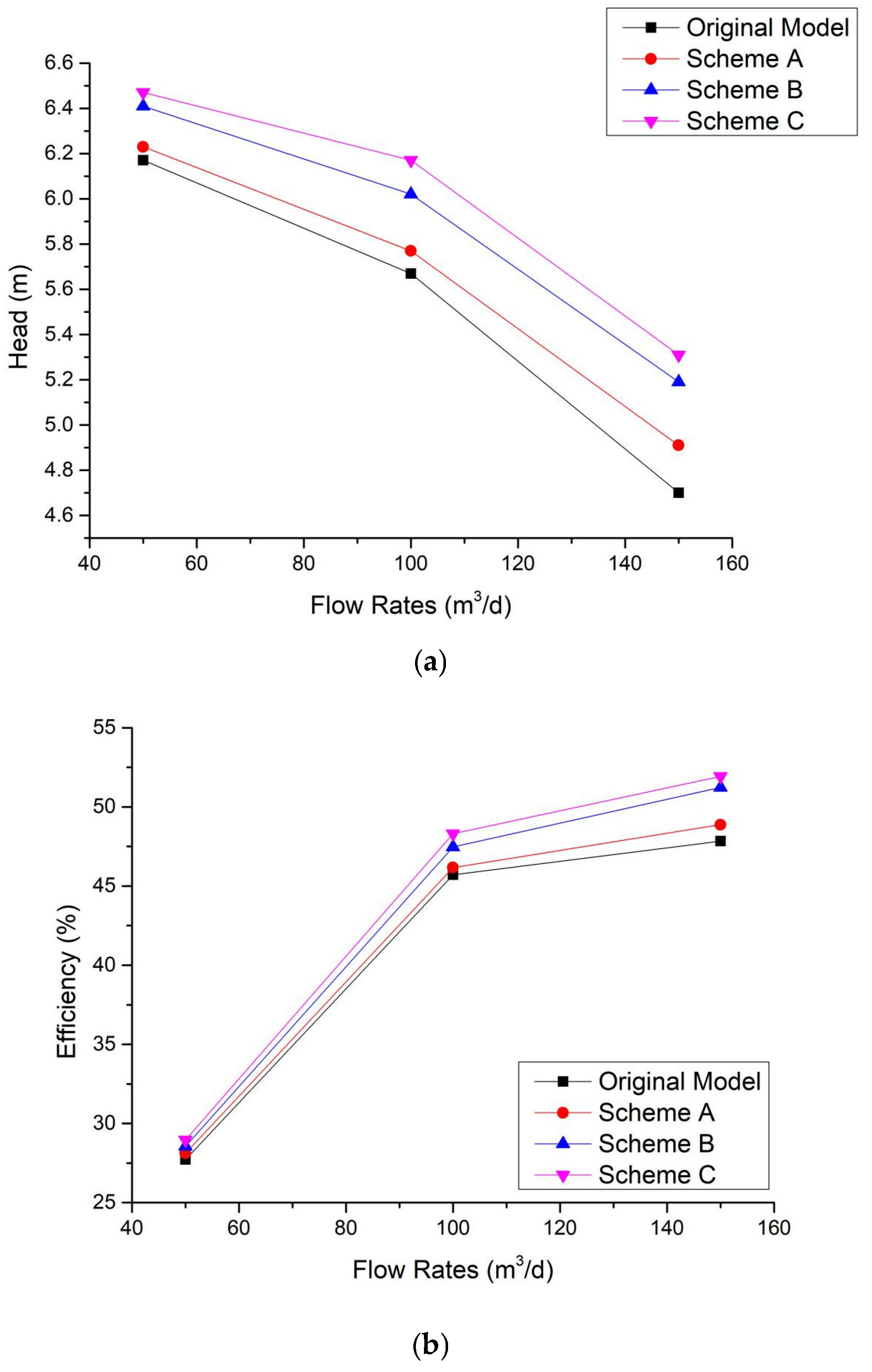
3.1.2. Simulation Analysis of Non-Smooth Structure Arrangement

Building on the shear stress peak regions identified in Figure 5, this study further evaluates the relationship between manufacturability and performance gains for different arrangement schemes. Considering machining feasibility constraints for suction surface leading-edge dimple arrays, three comparative schemes were designed: Scheme A (pressure surface trailing edge only), Scheme B (suction surface leading edge only), and Scheme C (dual-region arrangement), all employing a uniform dimple diameter of 0.9 mm (Figure 9).
Numerical simulation results reveal the following:
  • Performance Degradation in Scheme B: At 150 m3/d, Scheme B achieved only a 4.47% head gain, representing a 65.56% reduction compared to Scheme A (12.98%).
  • Marginal Benefits of Dual-Region Optimization: Scheme C provided merely a 2.55-percentage-point head improvement over Scheme A, with efficiency gain differences below 1.5%.
  • Dominant Role of Pressure Surface Trailing Edge: Dimples on the pressure surface trailing edge exhibited superior contributions to both head and efficiency enhancements.
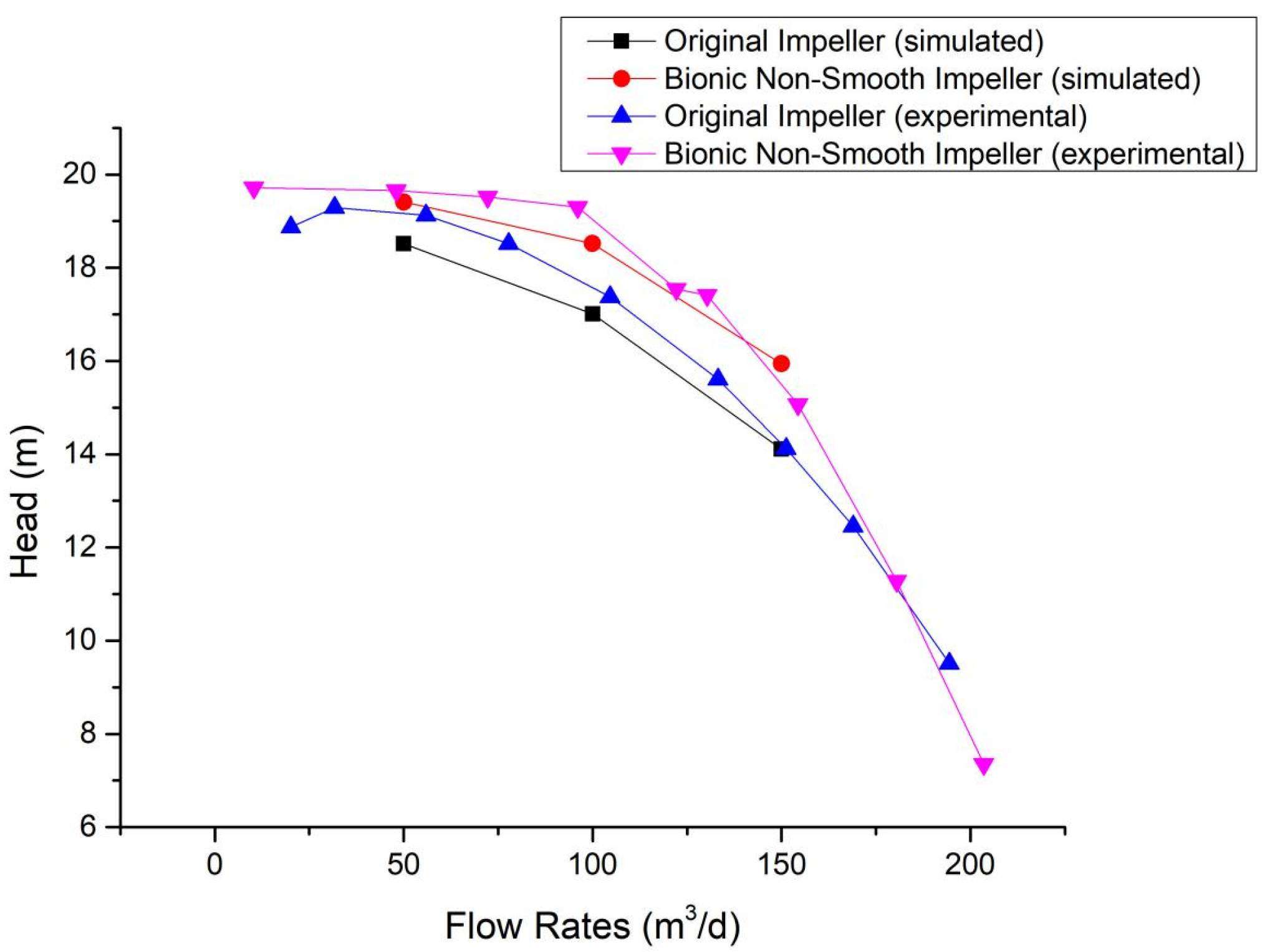
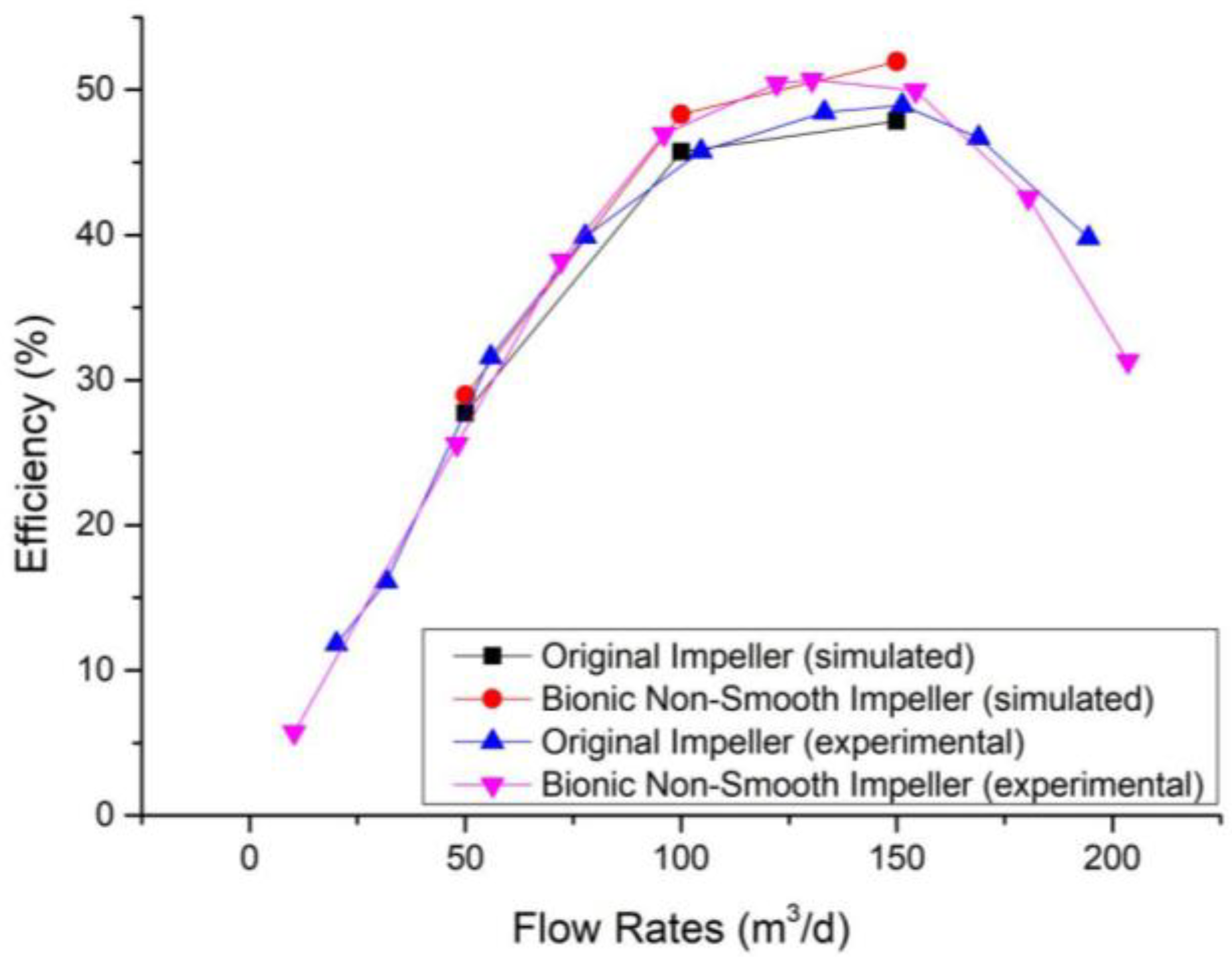
These phenomena are attributed to stronger shear layer instabilities at the pressure surface trailing edge, where non-smooth structures more effectively suppress boundary layer separation. For engineering applications, Scheme A is recommended for single-region optimization, achieving over 90% of the maximum performance gain while maintaining practical manufacturability.

3.2. Experiment

To efficiently validate the reliability of the numerical model, a prototype was manufactured via 3D printing (Figure 10). Stereolithography (SLA) was selected for this study due to its high resolution and sufficient mechanical strength [31]. Key process parameters were set as follows: layer thickness: 50 μm, UV curing wavelength: 405 nm, and post-processing curing time: 90 min. Coordinate measuring machine (CMM) results confirmed machining errors of critical dimensions within ±0.15 mm and surface roughness Ra ≤ 6.3 μm. The UV post-curing treatment ensured sufficient mechanical strength to meet experimental requirements.
Figure 11 compares the experimental and simulated head and efficiency values of the original model and the bionic non-smooth impeller. For head characteristics, the experimental and simulated head-flow curves exhibit consistent trends, though the experimental head values demonstrate a systematic overestimation with a maximum relative deviation of less than 3%. Among these, deviations were particularly pronounced under low-flow conditions, primarily attributed to unaccounted wall roughness effects and clearance leakage in the numerical simulations. The optimized impeller achieved a maximum head improvement of 11.5% at 130 m3/d, showing a 7.9% relative deviation compared to the simulated prediction of 12.98%.
Figure 12 presents the experimental and simulated efficiency curves for the original model and bionic non-smooth impellers. Comparative analysis reveals that the experimental and simulated efficiencies deviate by less than 2% in the low-flow regime (50–100 m3/d). However, the deviation increases to 4% at 150 m3/d directly correlated with the reduced predictive accuracy of the turbulence model under high Reynolds number conditions. The optimized impeller achieved a peak efficiency of 50.67% at 130 m3/d, representing a 4.6-percentage-point improvement over the prototype but falling 45.8% short of the simulated prediction (8.55%). This discrepancy indicates insufficient characterization of secondary flow losses in the numerical model. The efficiency enhancement exhibits distinct flow dependency: gains remain below 1.2% in the 50–100 m3/d range but increase significantly to 2.8–4.6% at 100–150 m3/d.

4. Discussion

The integration of bio-inspired dimple-type non-smooth surfaces into wide-range electric submersible centrifugal pumps (ESPs) demonstrates significant potential for enhancing hydraulic performance under dynamic reservoir conditions. The findings align with prior studies emphasizing the efficacy of bio-inspired surfaces in drag reduction and efficiency optimization [14,15,16,17,18,19], while also extending their application to low-flow, multiphase flow regimes typical of offshore oilfields. This study corroborates the hypothesis that localized placement of non-smooth structures in high-shear-stress regions maximizes drag reduction benefits, as proposed by Dai et al. [25]. The observed head gain of 12.98% (simulation) and 11.5% (experiment), alongside efficiency improvements of 8.55% and 4.6%, respectively, highlight the critical role of pressure surface trailing-edge optimization in suppressing boundary layer separation. However, the nonlinear relationship between dimple size and performance underscores the necessity of multi-parameter optimization to balance hydraulic gains with manufacturability constraints.
Table 2 presents the relative deviations between experimental data and numerical predictions at different flow rates. As shown in Table 2, significant efficiency deviation occurs at low flow rates, where head is systematically overestimated while efficiency is consistently underestimated.
Discrepancies between experimental and numerical results primarily stem from the following three mechanisms:
  • Simplification of anisotropic wall roughness modeling: Actual pump wall roughness exhibits anisotropy, whereas simulations adopt an isotropic model. This simplification underestimates turbulent dissipation, leading to inaccurate boundary layer predictions. At low flow rates, boundary layer separation exhibits heightened sensitivity to roughness anisotropy; neglecting this effect results in underestimated frictional losses and consequently overpredicted efficiency. Furthermore, the isotropic assumption causes overpredicted head at high flow rates (where actual head is lower due to greater frictional losses), despite enhanced hydrodynamic influence of the bionic non-smooth surfaces.
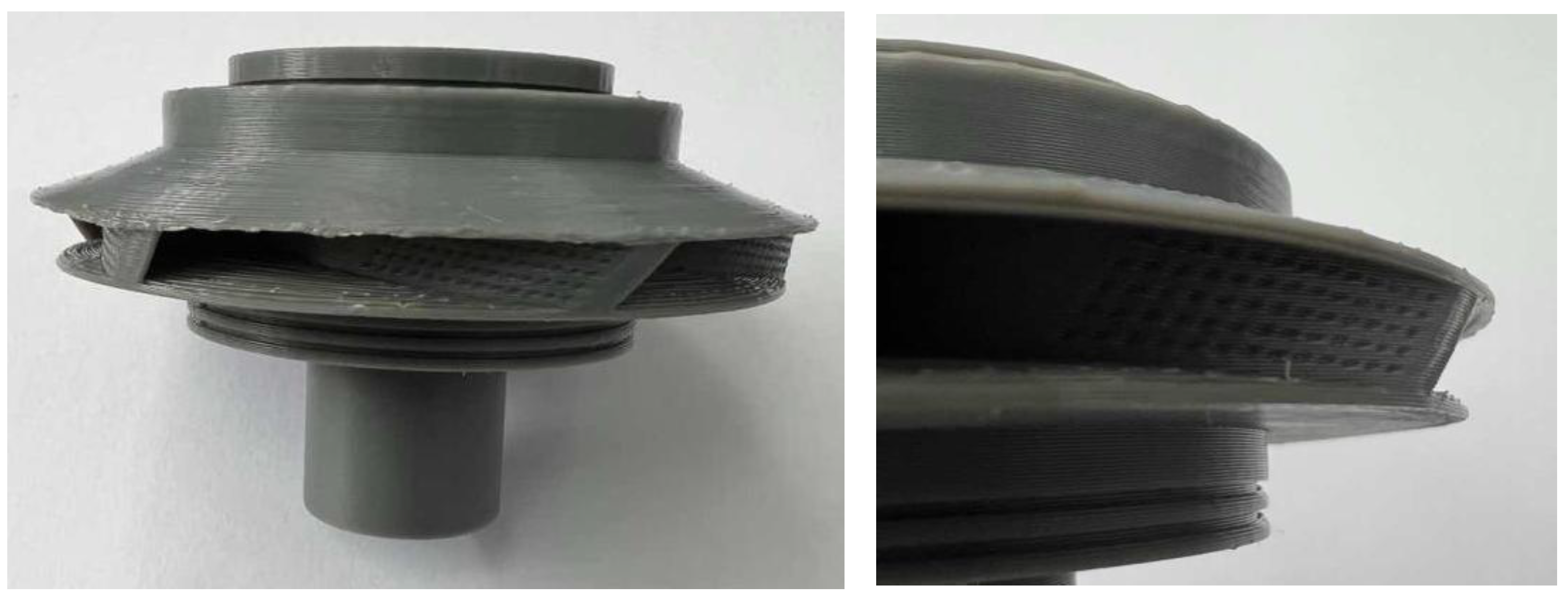
  • Microstructural defects in 3D-printed components: Layer lines, pores, and other printing-induced defects increase surface roughness and induce unintended vortices, reducing actual efficiency. This effect is particularly pronounced for bionic non-smooth impellers: the 0.9 mm radius of dimple structures approaches the ±0.15 mm printing tolerance, rendering experimental specimens highly susceptible to surface defects that persistently reduce efficiency below simulated values.
  • Random deviations from flowmeter/pressure sensor calibration errors and mechanical vibrations.
Furthermore, the limitations of the k-ω turbulence model at high Reynolds numbers partially explain discrepancies between simulations and experiments, particularly in efficiency prediction accuracy. Its incomplete capture of secondary flow losses and strong turbulent mixing effects in actual flows exacerbates deviations in high-flow-rate regions. Nevertheless, the consistent trends observed between simulations and experiments demonstrate the model’s robustness in near-wall flow characterization, supporting its utility in preliminary design stages. The positive correlation between efficiency gain and flow rate—with minimal gains at low flow rates (<100 m3/d) and significant enhancement at high flow rates—indicates that biomimetic surfaces offer particular advantages during production peaks. This characteristic aligns closely with operational requirements in offshore oilfields.
The implications of this work extend beyond ESP optimization. By expanding high-efficiency operating ranges, the technology reduces pump replacement frequency and energy consumption, directly addressing sustainability goals in offshore oil production. The 3D-printed prototype’s successful fabrication further highlights additive manufacturing’s potential for rapid iteration of complex bio-inspired geometries, a critical enabler for industrial adoption. However, long-term durability under abrasive multiphase flows remains unverified.
Future research should prioritize the following three areas:
  • Wear Resistance Evaluation: Investigating material coatings or hybrid surface textures to enhance durability in abrasive environments.
  • Multi-Objective Optimization: Integrating machine learning with CFD to explore synergistic effects of dimple parameters (depth, spacing, distribution) and alternative bio-inspired geometries (e.g., riblets, hierarchical structures).
  • Field-Scale Validation: Testing optimized impellers in real-world offshore conditions to assess performance under variable oil–water ratios, gas ingress, and thermal stresses.
By addressing these challenges, bio-inspired surface engineering could revolutionize not only ESP systems but also broader applications in turbomachinery and renewable energy systems, fostering a new paradigm of energy-efficient fluid handling technologies.

5. Conclusions

This study systematically investigates the drag reduction and efficiency enhancement mechanisms of dimpled non-smooth surface structures in wide-range electric submersible centrifugal pumps through bioinspired structural optimization. Key findings are summarized as follows:
(1)
The dimpled non-smooth structure effectively suppresses boundary layer separation near the impeller wall and reduces viscous friction losses. Numerical simulations indicate that the optimized impeller (dimple diameter d = 0.9 mm) achieves 12.98% and 8.55% improvements in head and efficiency, respectively, compared to the baseline impeller at 150 m3/d. Experimental validation confirms an 11.5% head gain and a 4.6-percentage-point peak efficiency enhancement at 130 m3/d.
(2)
Dimple diameter exhibits a nonlinear correlation with performance gains, with d = 0.9 mm yielding optimal overall performance. The structural arrangement significantly impacts drag reduction, where dimple arrays on the trailing edge of the pressure side maximize efficiency by regulating shear layer instability.
(3)
Experimental and simulated head-flow curves align in trend, but experimental head values are systematically 1.2–2.8% higher, with a 4% efficiency deviation at 150 m3/d. These systematic errors arise from the combined effects of anisotropic wall roughness, multiphase flow interface slip, and additive manufacturing micro-defects.
(4)
The single-region optimization strategy (dimples on the pressure side trailing edge) achieves over 90% of the total performance improvement while maintaining high manufacturability, offering a practical solution for dynamic adaptability of wide-range pumps and intelligent well completion technologies.
Future work should focus on long-term wear characterization of non-smooth structures in multiphase flows and the development of machine learning-based algorithms for multi-parameter co-optimization to enhance adaptive performance under complex operating conditions. Additionally, integrating real-time monitoring technologies will accelerate the engineering application of bioinspired drag-reduction structures in intelligent oil recovery systems.

Author Contributions

Conceptualization, T.F. and S.W.; methodology, S.W.; software, T.F.; validation, T.F., S.W. and Y.G.; formal analysis, T.F. and B.S.; writing—original draft preparation, T.F.; writing—review and editing, B.S. All authors have read and agreed to the published version of the manuscript.

Funding

This research was funded by the Youth Innovation Project Fund (2022-40220-000158-KTY), Research Institute of Petroleum Exploration and Development, PetroChina Company Limited.

Institutional Review Board Statement

Not applicable.

Informed Consent Statement

Not applicable.

Data Availability Statement

The original contributions presented in this study are included in the article. Further inquiries can be directed to the corresponding author.

Acknowledgments

Special thanks to RIPED’ s Research Department for providing critical infrastructure access and technical coordination, enabling efficient progress at key project stages.

Conflicts of Interest

Authors Tao Fu, Songbo Wei, Yang Gao and Bairu Shi were employed by the company PetroChina Company Limited. All of the authors declare that the research was conducted in the absence of any commercial or financial relationships that could be construed as a potential conflict of interest. The sponsors had no role in the design, execution, interpretation, or writing of the study.

Abbreviations

The following abbreviations are used in this manuscript:
ESPElectrical submersible pumps
CFDComputational fluid dynamics
MRFMultiple reference frame

References

  1. Li, Y.; Bai, J.; Yu, F.; Shang, B.; Jiang, Z.; Du, D. Research and Application of Wide-Range Electrical Submersible Pump Lifting Technology in Bohai Oilfield. J. Chengde Pet. College 2023, 25, 20–26+36. [Google Scholar] [CrossRef]
  2. Li, H.; Wang, Q.; Jiang, Z.; Yu, F.; Hou, X.; Yu, X. Research and Application of Permanent Magnet Motor-Driven Electrical Submersible Pump Technology in Bohai Oilfield. China Pet. Chem. Stand. Qual. 2023, 43, 193–195. [Google Scholar]
  3. Cheng, S. Analysis of Efficiency Optimization and Energy Saving for Centrifugal Pump Impellers. China Plant Eng. 2021, 13, 148–149. [Google Scholar]
  4. Zhang, J. Operation and Common Issue Mitigation of Centrifugal Pumps in Oilfield Production. China Sci. Technol. J. Database (Ind. A) 2022, 1, 43–46. [Google Scholar]
  5. Saputra, M.N.; Rahmanto, B.A.; Anggaraini, H.; Ryanta, A. Enhancing Reliability and Emissions Reduction: The Impact of Compact Wide Range Electrical Submersible Pumps. In Proceedings of the International Petroleum Technology Conference, Kuala Lumpur, Malaysia, 18–20 February 2025. [Google Scholar] [CrossRef]
  6. Shuber, H.; Al-Watyan, A.; Alaryan, A.; Kishore, K.; Aparicio, C.; Yadavalli, S.; Cai, H.B. Success Story: Selective Completion Combined with Wide-Range ESP in KOC. In Proceedings of the ADIPEC, Abu Dhabi, United Arab Emirates, 2–5 October 2023. [Google Scholar] [CrossRef]
  7. Niu, C.; Gan, Q.; Zheng, T.; Zhang, L.; Li, B.; Wei, W.; Yang, H. Application Analysis of Wide-Range Electrical Submersible Pump Lifting Technology in Tight Oil Horizontal Wells. Oil Field Equip. 2021, 50, 69–74. [Google Scholar]
  8. Leon, F.I.; Alvear, J.L.; Naranjo, R.R.; Vela, N.A.; Amores, D.A.; Perez, M.A.; Pancho, J.G.; Aguirre, L.X.; Sierra, O.G.; Villalobos, J.L.; et al. Comparative Study of the World’s First Deployment of a Compact Wide-Range ESP System with Induction Motor at MDC Field, Ecuador. In Proceedings of the ADIPEC, Abu Dhabi, United Arab Emirates, 4–7 November 2024. [Google Scholar] [CrossRef]
  9. Pasaribu, R.; Purba, M.O.; Anggaraini, H.; Alkahfi, S.; Fatichin, F.; Rahmanto, B.; Junaidy, I.; Andri, F.; Abadi, F. The Success Story of ESP Advanced Technology Application to Address the Risk of Well Inflow Capability Uncertainty Using a Wide Range and Abrasive-Resistant ESP in the B and K Fields. In Proceedings of the SPE Middle East Artificial Lift Conference and Exhibition, Manama, Bahrain, 29–30 October 2024. [Google Scholar] [CrossRef]
  10. Wei, M.; Che, C.; Gong, J.; Sun, J.; Qi, L. Structural Design and Internal Flow Field Analysis of Wide-Range Electrical Submersible Pumps. Pump Technol. 2023, 5, 11–15. [Google Scholar]
  11. Li, Y.; Bai, J.; Jiang, Z.; Yu, F.; Shang, B. Design and Performance Testing of Wide-Range Electrical Submersible Pump Impeller-Diffuser Assemblies. Oil Field Equip. 2020, 49, 66–73. [Google Scholar]
  12. Wang, Z.; Li, J.; Hou, D.; Qiao, Y.; Wu, M. Research and Application of Wide High-Efficiency Hydraulic Design Methods for Centrifugal Pumps. Energy Conserv. Technol. 2024, 42, 353–358. [Google Scholar]
  13. Dai, C.; Ge, Z.P.; Dong, L.; Liu, H.L. Drag and Noise Reduction Characteristics of Bionic Surfaces in Centrifugal Pumps. Journal of Huazhong Univ. Sci. Technol. (Nat. Sci. Ed.) 2020, 48, 113–118. [Google Scholar] [CrossRef]
  14. Wu, W.; Wang, G.; Zhou, Z.; Guan, L. Drag Reduction Performance of Bionic Non-Smooth Surfaces. Contemp. Chem. Ind. 2024, 53, 855–859. [Google Scholar] [CrossRef]
  15. Zhong, P.; Zhao, X.; Ni, W.; Yang, K. Design and Finite Element Analysis of Bionic Non-Smooth Surface Pipelines. Hydraul. Pneum. 2019, 7, 70–75. [Google Scholar]
  16. Wang, Z.; Chen, P.; Hu, O. Drag Reduction Technology for Helicopter Tail Cabin Doors Based on Non-Smooth Surfaces. J. Nanjing Univ. Aeronaut. Astronaut. 2020, 52, 240–246. [Google Scholar] [CrossRef]
  17. Zhu, H.; Zhang, Y.; Wu, P.; Shao, X. Boundary Layer Control-Based Drag Reduction Technology for High-Speed Trains. J. Traffic Transp. Eng. 2017, 17, 64–72. [Google Scholar]
  18. Huang, S. Application of Bionic Non-Smooth Theory in Oil and Gas Well Engineering. Petrochem. Ind. Technol. 2015, 8, 108. [Google Scholar]
  19. Shi, B.; Yang, Q.; Hao, Z.; Wei, S.; Fu, T. Bionic Surface Textured Stator for Deep/Ultra-Deep Well Oil Production Progressing Cavity Pump. In Proceedings of the APOGCE 2024, Perth, Australia, 15–17 October 2024. [Google Scholar] [CrossRef]
  20. Lin, X.C.; Hu, Y.H.; Li, Q.Y.; Wang, Y.; Chen, J. Impact of Bionic Micro-Dimple Surface Blades on Cavitation Performance of Centrifugal Pumps. Hydraul. Pneum. 2024, 48, 143–149. [Google Scholar]
  21. Gan, G.; Hu, Y.; Zhang, X.; Yuan, X.; Li, J.; Ning, T. Effect of Non-Smooth Surface Blades on Hydraulic Performance of Centrifugal Pumps. J. Mech. Electr. Eng. 2023, 40, 781–787. [Google Scholar]
  22. Mu, J.G.; Dai, D.S.; Gu, Y.Q.; Liu, J.; Zheng, S.H.; Wang, E. Flow Drag Reduction Characteristics of Non-Smooth Surface Centrifugal Pump Impellers. J. Shanghai Jiao Tong Univ. 2016, 50, 306–312. [Google Scholar] [CrossRef]
  23. Dai, D. Application of Non-Smooth Surface Flow Drag Reduction Characteristics in Centrifugal Pumps. Ph.D. Thesis, Zhejiang University of Technology, Hangzhou, China, 2015. [Google Scholar]
  24. Li, K. Research on Drag Reduction of Bionic Dimpled Impellers and Dynamic Characteristics of Centrifugal Pump Units. Ph.D. Thesis, Harbin Engineering University, Harbin, China, 2017. [Google Scholar]
  25. Dai, C.; Chen, Y.; Dong, L.; Wang, Z. Optimal Placement of Bionic Non-Smooth Structures on Centrifugal Pump Blades. J. Drain. Irrig. Mach. Eng. 2020, 38, 241–247. [Google Scholar]
  26. Peng, Q.; Hu, H.; Wang, F.; Zhang, G. Drag Reduction Performance of Non-Smooth Pipeline Walls. Mech. Des. Manuf. 2017, 41, 126–129. [Google Scholar] [CrossRef]
  27. Chen, Q. Unsteady Flow and Cavitation Characteristics of Centrifugal Pumps Under Low-Flow Conditions. Ph.D. Thesis, Shandong University of Science and Technology, Qingdao, China, 2022. [Google Scholar] [CrossRef]
  28. Choi, H.G.; Yoo, J.Y. A Hybrid Numerical Method for Navier-Stokes Equations Based on SIMPLE Algorithm. Numer. Heat. Transf. Part B Fundam. 1995, 28, 155–170. [Google Scholar] [CrossRef]
  29. Wang, W.; Tang, T.; Lu, S.P. Cavitation Suppression by Grooves on Suction Surface of Hydrofoils. Trans. Chin. Soc. Agric. Eng. 2019, 35, 40–47. [Google Scholar]
  30. EN ISO 5198:1998; Centrifugal, Mixed Flow and Axial Pumps-Hydraulic Performance Acceptance Tests-Precision Class. ISO: Geneva, Switzerland, 1998.
  31. Tavares, J.A.; Aldakhil, D.A. The Utilization of 3D Printing in O&G Applications. In Proceedings of the International Petroleum Technology Conference, Dhahran, Saudi Arabia, 12–14 February 2024. [Google Scholar] [CrossRef]
Figure 1. Wide-range electric submersible centrifugal pump: (a) impeller; (b) guide vane.
Applsci 15 07989 g001
Figure 2. Computational domain: (a) global domain; (b) impeller subdomain; (c) guide vane subdomain.
Applsci 15 07989 g002
Figure 3. Mesh discretization.
Applsci 15 07989 g003
Figure 4. Pump head and efficiency at varying mesh densities.
Applsci 15 07989 g004
Figure 5. Shear stress distribution of oil-water two-phase flow on the ESP impeller surface.
Applsci 15 07989 g005
Figure 6. Dimple-type non-smooth structures: (a) on leading edge of suction surface; (b) on trailing edge of pressure surface; and (c) parametric configuration of non-smooth surface structures.
Applsci 15 07989 g006
Figure 7. Schematic diagram of the experimental setup.
Applsci 15 07989 g007
Figure 8. Performance of dimple-type non-smooth impellers under varying flow rates: (a) head; (b) efficiency.
Applsci 15 07989 g008
Figure 9. Performance of centrifugal pumps with dimple-type non-smooth structures at different locations: (a) head; (b) efficiency.
Applsci 15 07989 g009
Figure 10. The 3D-printed impeller prototype.
Applsci 15 07989 g010
Figure 11. Head comparison curves.
Applsci 15 07989 g011
Figure 12. Efficiency comparison curves.
Applsci 15 07989 g012
Table 1. Key parameters for CFD simulations.
CategoryParameterValue
Fluid propertiesOil–water ratio1:9 (volumetric)
Oil density850 kg/m3
Water density998 kg/m3
Dynamic viscosity0.001 Pa·s
Boundary conditionsInlet velocity50−150 m3/d
Rotational speed3500 rpm
Boundary conditionsVelocity inlet, pressure outlet
Numerical settingsTurbulence modelStandard k-ω
Near-wall treatmentEnhanced Wall Function
ConvergenceResiduals < 10−5
Table 2. Relative deviations: experimental vs. simulated data.
Flow Rate
(m3/d)
Head Deviation (%)Efficiency Deviation (%)
Original ImpellerBionic Non-Smooth ImpellerOriginal ImpellerBionic Non-Smooth Impeller
503.30 1.24 13.92 −11.64
1002.12 4.27 0.07 −2.82
1500.07 −5.46 2.24 −3.81
Disclaimer/Publisher’s Note: The statements, opinions and data contained in all publications are solely those of the individual author(s) and contributor(s) and not of MDPI and/or the editor(s). MDPI and/or the editor(s) disclaim responsibility for any injury to people or property resulting from any ideas, methods, instructions or products referred to in the content.

