1. Introduction
The underground mining operations during mineral extraction certainly has effects on buildings and structures located nearby, as well as on the Earth’s surface [
1,
2,
3,
4,
5]. Soil deformations during underground mining have the character of not only uneven settlement, but also horizontal displacement of soils, which leads to the loss of stability of foundations and the building structure itself [
1,
2,
3]. Coal deposits are characterized by their stratified occurrence [
2,
3,
4]. Often, several coal seams, called suites, are found at different depths in one deposit.
A significant part of Karaganda region cities and villages in Kazakhstan are located on the areas affected by underground mining (
Figure 1), while Karaganda city itself is almost entirely located on coal deposits and coal reserves [
1,
2,
3,
4,
5]. The foundation soil that can serve as a reliable support for buildings lies at a depth of 6–8 m from the Earth’s surface) [
4,
5]. The Karaganda coal basin ranks third in the CIS (after Kuzbass and Donbass) [
4].
The conditions of the seams’ occurrence can be very diverse—from horizontal and gently sloping, with an angle of incidence of α ≤ 25°, to inclined (α ≤ 45°) and steep (α > 45°). As a result of coal extraction from the depths, the rock strata covering it is displaced into the resulting cavity, and a bowl-shaped depression, called a displacement trough, forms on the Earth’s surface.
According to Müller [
6], a zone of destructive displacements exceeding permissible deformations (limit values for ensuring the stability of buildings, according to the Standards [
7,
8] in Kazakhstan) and a zone of relatively safe displacements with minor deformations of the foundation soil, are distinguished. Destructive displacements caused by underground mining often occur not only within the central subsidence trough, but also along its margins, where tensile strains and differential ground movements are most pronounced. Their impact on construction depends on several geotechnical factors, including the subsidence potential of the foundation soil, local slope and curvature (convex or concave), horizontal displacements, and the presence and height of existing step-like deformations along the slope [
6].
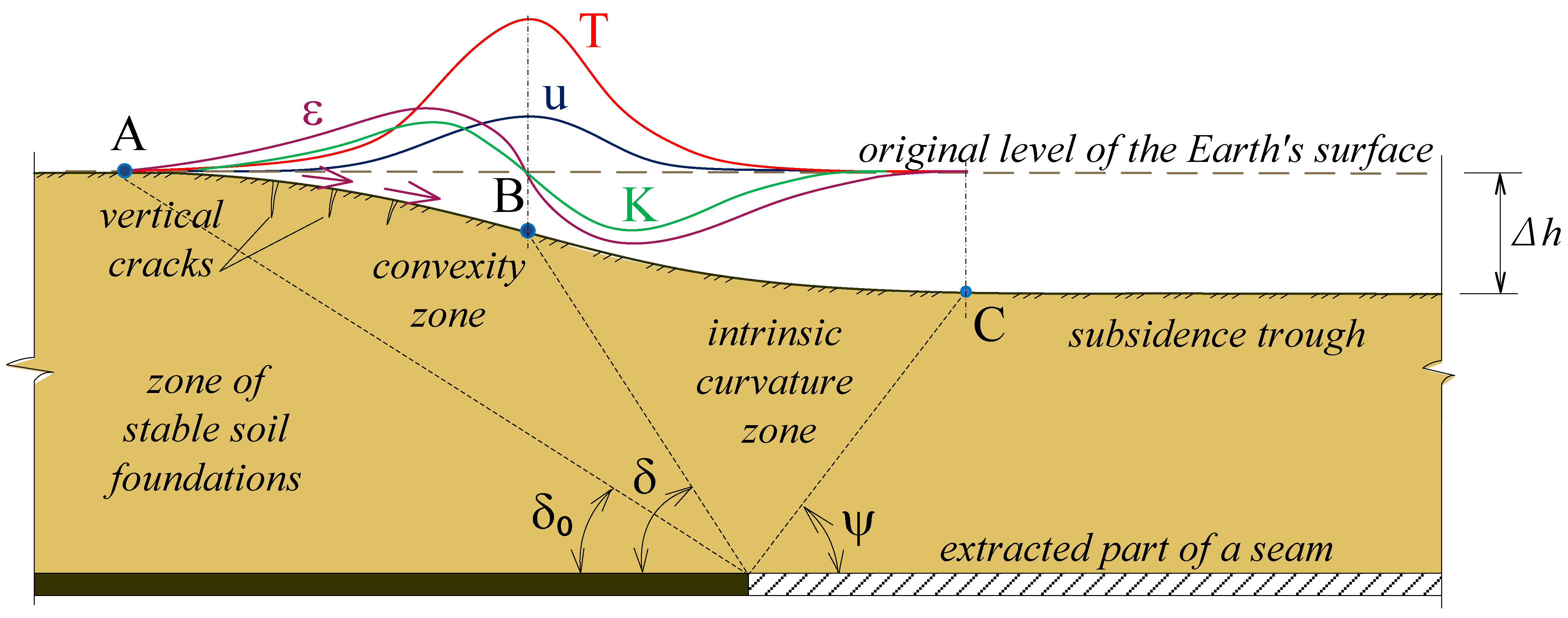
As the minerals are mined underground and the working area expands, the surface points undergo further stages of deformation, in turn (
Figure 2) [
9,
10]: a section with positive curvature (convexity) and tensile strains (section AB), a zone of negative curvature and horizontal compression strains (section BC) and a zone above the subsidence trough. In the latter, all points of the surface depressed into the flat bottom of the displacement trough, with possible horizontal tensile deformations, are transferred from stages 1 and 2.
A more detailed description of the stress–strain state of the soil layer in the undermining areas was presented in a study by Zhussupbekov et al. [
9]. Measures to prevent unacceptable deformation in foundation structures of buildings and structures require enormous labor costs and excess material consumption, which affects the economic feasibility of construction in this region. In the previous work, conical foundations experimentally proved their effectiveness in horizontal tensile soil displacements, especially in the convexity zone [
9]. Conical foundations represent a specialized type of substructure used for efficient distribution of load, particularly in areas with weak or layered soil conditions. The geometric advantage of a tapered profile enhances the bearing capacity, reduces stress concentration, and improves stability against overturning and uplift. Conical foundations are frequently employed in transmission towers, telecommunication masts, and offshore wind structures, where lateral and uplift forces are critical.
The analytical basis for conical and other sloped footings originates from the pioneering work of Ludwig Prandtl [
11], who introduced the theory of plastic equilibrium for soil under punching shear—a concept particularly applicable to cone-shaped loading zones. Later, Karl Terzaghi [
12] formalized these ideas by deriving bearing-capacity equations for strip footings, which were subsequently adapted to cone geometries through the use of shape and depth correction factors.
In the 1950s, G.G. Meyerhof extended bearing-capacity theories to account for sloped, eccentric, and inclined loads, which are directly relevant to conical foundations [
13]. His corrections for shape, embedment depth, and load inclination significantly improved the realism of conical footing design [
10]. J.B. Hansen [
14] further refined these models by introducing empirical shape and load factors, making it easier to incorporate irregular geometries like conical profiles. A.I. Vesic [
15] advanced the theoretical framework by introducing soil compressibility and elasticity into bearing-capacity calculations.
Conical foundations have attracted growing interest in recent decades, due to their ability to improve vertical load-bearing performance, particularly in soft or variable soils. Their geometry allows for enhanced load dispersion and the mobilization of broader passive resistance zones compared to flat or shallow foundations. These characteristics have been studied extensively, using both experimental testing and numerical modeling approaches.
Keawsawasvong [
16] addressed a significant gap in foundation engineering by developing novel plastic solutions for the bearing capacity of conical footings in anisotropic and non-homogeneous clays, using finite element limit analysis (FELA). The study introduced key dimensionless parameters—such as cone angle and strength gradient—to provide more reliable design predictions for offshore conical foundations, including spudcans. Cassidy and Houlsby [
17] investigated conical footings in sandy soils through centrifuge testing, demonstrating that cone geometry mobilizes broader failure surfaces and offers higher normalized bearing capacities than flat bases. Similarly, Houlsby and Martin [
18] presented theoretical bearing-capacity factors for circular conical footings on undrained clays, incorporating variables such as embedment depth cone angle, and increasing undrained strength with depth—findings especially relevant for gravity bases and other large-scale offshore foundations.
Advancements in material innovation and foundation optimization have led to novel systems like the cone-shaped hollow flexible reinforced foundation (CHFRF), introduced by Li et al. [
19]. This system reduces material use while improving lateral load performance through embedded depth and the use of laminated rubber–steel layers for energy dissipation. In a related effort, Kritesh et al. [
20] combined FELA and the MARS model to show that base roughness significantly improves the bearing capacity of conical footings. Nguyen Van et al. [
21] and Lai et al. [
22] further demonstrated, using machine learning and FEA-ANN methods, that conical footing behavior is highly sensitive to cone geometry and soil heterogeneity, yielding accurate predictive models for design.
These studies confirm the theoretical advantages of conical geometries: better load dispersion, improved settlement control, and enhanced resistance to overturning. However, conical foundations also present specific challenges—most notably, the risk of soil extrusion beneath sloped edges, particularly when the embedment depth is shallow. To overcome these limitations and enhance both vertical and lateral stability, this study proposes a cone-top pile foundation, combining a conical base (with the apex pointing downward) and a centrally embedded pile shaft. This hybrid configuration improves resistance to soil deformation and allows for deeper load transfer. The proposed foundation system also draws conceptual parallels with micropile-supported systems, such as those examined by Omarov et al. [
23], which demonstrated high performance in layered soils under static and dynamic loads. While conical geometry addresses vertical load efficiency, incorporating a central pile addresses lateral force demands more effectively. In this regard, the findings of Sivapriya and Gandhi [
24], who studied lateral pile behavior in sloped clayey soils, further support the need for such composite foundation systems. The integration of a central pile with a conical head leverages the strengths of both geometries, offering a robust solution in conditions requiring strain isolation, improved settlement control, and resistance to multi-directional loading. Zou et al. [
25] investigated the failure mechanisms and combined bearing behavior of a monopile–friction wheel hybrid foundation in sand-over-clay deposits, demonstrating improved load capacity and deformation control through hybrid foundation configurations.
The main objective of this study was to build upon the findings of the previous studies, by developing a hybrid conical foundation with an integrated pile stand. This new design aims to retain the advantageous geometry of the conical shape foundation, known for its effective response under tensile stress and enhanced stability in zones susceptible to horizontal displacements within soil massifs adjacent to underground mine workings. In addition, the incorporation of a pile stand is expected to significantly improve bearing capacity, thereby enhancing the overall load-bearing performance and reducing settlement effects.
2. Materials and Methods
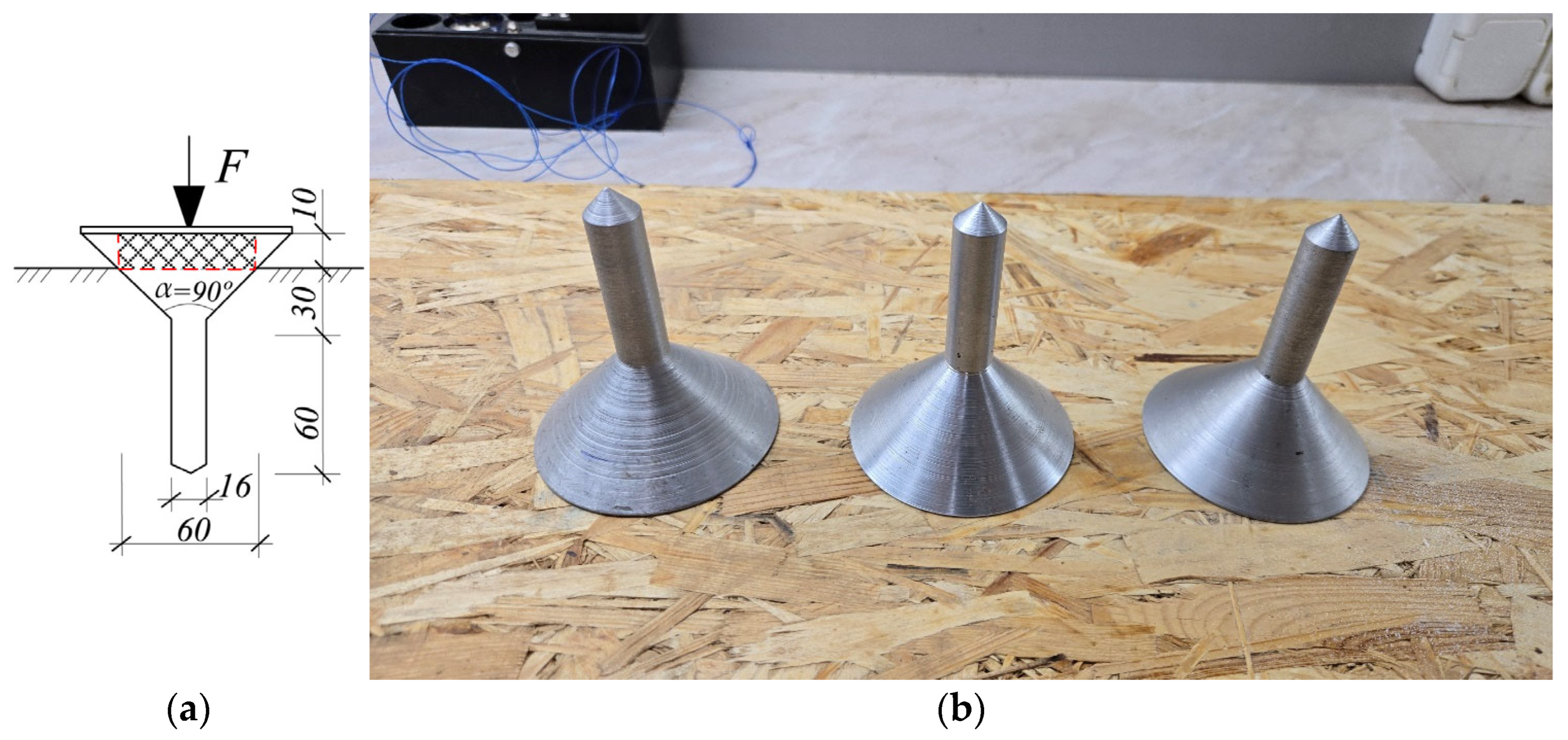
The study used an inverted conical foundation top with pile-stand (
Figure 3c), with the wider base at the top and the narrow tip extending down into the soil, to improve load distribution near the surface and increase resistance to uplift and lateral forces. Comparing the bearing capacity of the presented model of a cone-top combined with a pile-stand, the models of an isolated shallow foundation and the classical conical model in
Figure 3 were also considered.
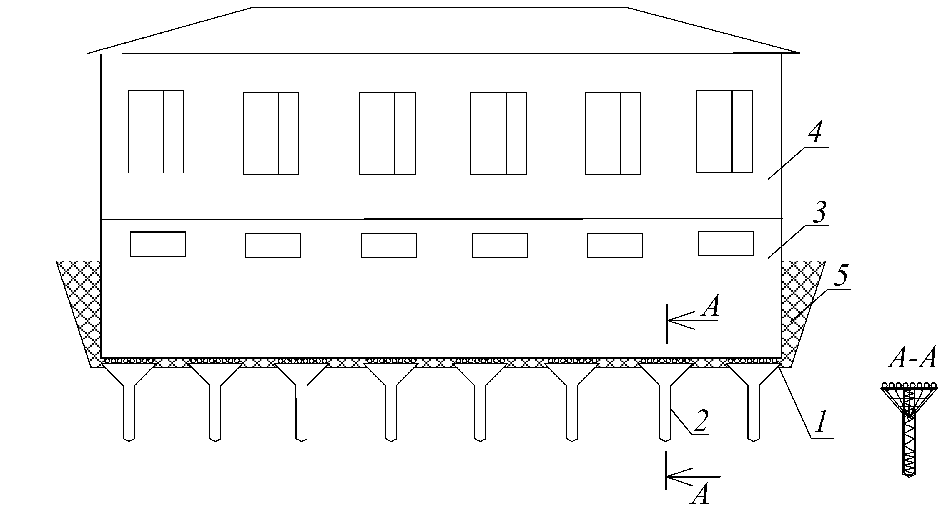
Conical foundations with a pile-stand have an increased load-bearing capacity, due to the combined pile, with a diameter equal to 0.3 d of the cone diameter. A reduction in the transfer of horizontal forces to the building is possible, due to the construction of a rolling joint, which neutralizes the horizontal impact of the horizontal strains on the upper part of the building. The rolling joint is a double ball bed installed on the foundation block (
Figure 4). This form of conical foundations allows for compensation of small horizontal soil movements during displacement of rock masses near the construction-site-affected area; as they settle, they increase their cross-section at the level of intersection with the Earth’s surface. and therefore increase their bearing capacity.
The study included laboratory tests of scale models subjected to static loading at specified horizontal soil displacement strains, numerical modeling consistent with laboratory test conditions, and field studies of static loading of a conical pile foundation model, based on measured horizontal displacements under real conditions.
2.1. Laboratory Testing
To study the bearing capacity in laboratory conditions, reduced-scale models of conical foundations were designed, as shown in
Figure 5. These models were tested on a laboratory bench to evaluate their load-bearing performance at a given value of horizontal soil displacement.
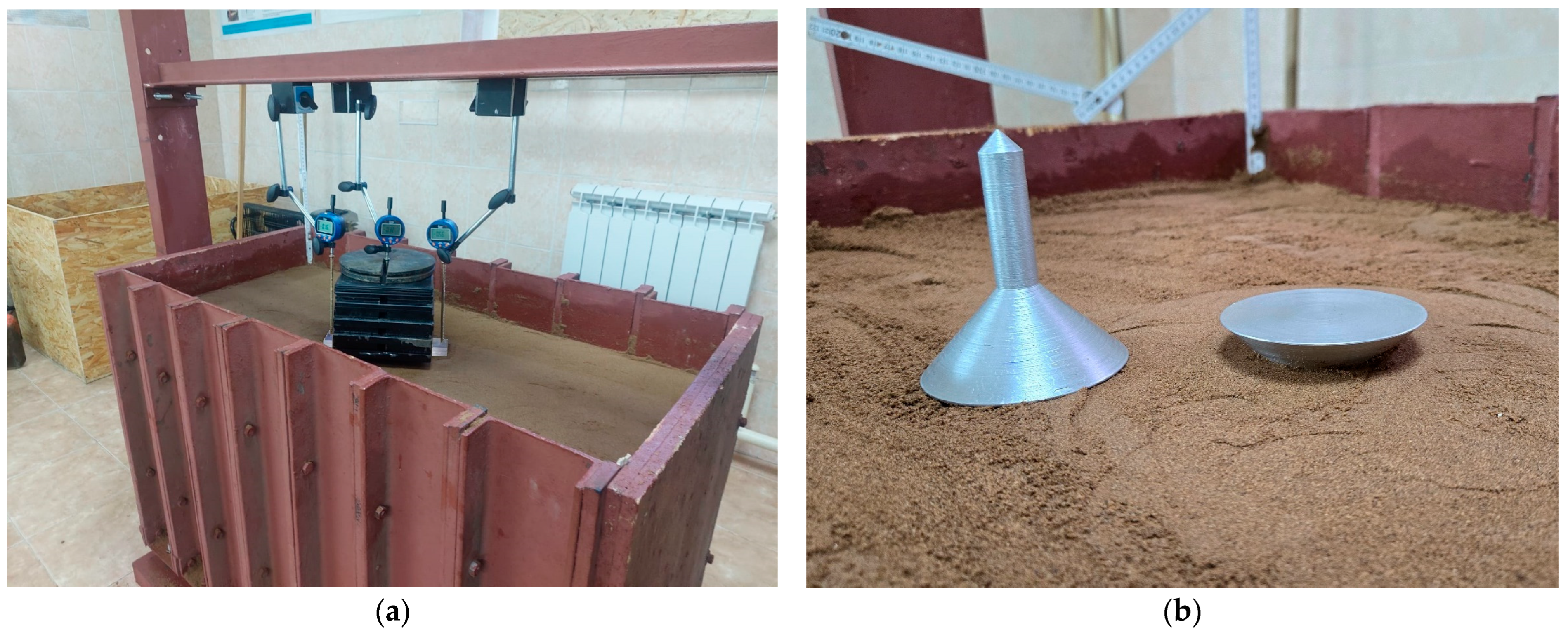
A three-dimensional expandable model box, filled with a compacted equivalent model soil, was used to simulate the effects of horizontal soil displacements. The equivalent material was compacted uniformly to achieve the target physical and mechanical properties (density, moisture content, and cohesion). The model box was then expanded to the required dimensions by loosening the bolts that connected the steel channel sections along its sides. To prevent soil leakage during expansion, rubber gaskets were installed at all joints. When the bolts were loosened, the gaskets expanded laterally, inducing controlled horizontal tensile strains in the soil of up to 3 mm/m, 6 mm/m, and 9 mm/m, thereby simulating the convex tensile strain zone shown in
Figure 2. This method replicates the horizontal displacements that may occur in zone AB due to mining-induced deformation, including settlement and potential microcracking of the foundation soil.
A detailed description of the expandable box design is provided in [
9].
The granulometric composition and properties of the equivalent model soil were selected to match the natural soil’s cohesion, plasticity characteristics, density, and water content, as summarized in
Table 1. The modeling scale
was determined using the strength similarity method, based on the ratio of cohesion and unit weight between the model and natural soils:
where
—linear scale;
, —specific gravity of model and natural materials;
, —cohesion of model material and soil in real conditions on the site (natural condition).
The model soil was prepared by mixing 97% fine sand with 3% spindle oil to enhance viscosity and achieve a target cohesion in the range of 0.8–1.0 kPa. This composition allowed the model to replicate the mechanical behavior of natural cohesive soils, while maintaining a cohesion scaling ratio of 1:40 relative to field conditions.
Conical model foundations were manufactured from aluminum alloy, according to the dimensions in
Figure 5. Each conical model was installed into the pre-compacted soil with the central pile (stand) and conical tip embedded to 70% of the cone height. Loading was applied incrementally, in steps of 0.001 MPa, and sustained until the settlement rate stabilized (defined as deformation attenuation of less than 0.01 mm over 15 min). The model was then loaded further, until the pressure reached 16.7 N/cm
2 over the foundation area (
Figure 6).
Vertical settlement was measured using high-precision dial gauges with a reading accuracy of 0.01 mm. The ultimate bearing capacity was taken as the load level at which the model foundation began to settle continuously. Settlement was recorded under four conditions: before horizontal displacement, during displacement at ε = 3 mm/m, ε = 6 mm/m, ε = 9 mm/m, and after the cessation of horizontal displacement.
2.2. Field Test
Field tests were performed near the mine field in the Karaganda region (Kazakhstan). The soils on the site included a topsoil layer, brown carbonate sandy loams with fine and medium sands (layer thickness 0.2–1 m) and dark gray, hard loams (layer thickness 2–6 m), described in detail in
Table 1.
To monitor ground surface deformations caused by underground mineral extraction, a 3 × 3 m grid was established on the ground surface (
Figure 7). Measurement benchmarks, embedded to a depth of 1.5 m, were installed at the intersections of the grid lines. In the centers of the cells of this grid, models of foundations with a conical top and a standing pile were placed. The load on the test foundations was applied incrementally, using metal plates, each weighing 12.5 × 10
3 N. Settlements of the foundations were measured using vertical displacement sensors. Displacement readings were taken at each load increment and monitored until stabilization, at each stage. After reaching the maximum test load (100 kN), unloading was also performed in stages, to observe rebound behavior. The settlement monitoring during the static load test was carried out in the absence of horizontal soil displacement, as well as with a horizontal displacement, measured at 2.7 mm per 1 m.
For a comparative analysis of the bearing capacity of cone-top pile foundations and isolated shallow foundations, identical static loading of isolated shallow (columnar) foundations was carried out. As a model of an isolated shallow foundation, round plate indenters with an area of A = 2462 cm2 were used, corresponding to the diameter of cone-top pile foundations at the intersection with the ground surface level. The use of circular plates ensured more uniform load distribution across the foundation base, whereas square plates tended to produce cracks at their corners, indicating stress concentration and non-uniform pressure distribution in those zones.
As a movable compensator, 50 mm diameter steel balls were used, secured to a 500 × 500 × 20 mm steel plate with the aid of viscous oils. The number of balls was determined based on the final load, ensuring that the load on each individual ball did not exceed the contact strength of the material.
2.3. Numerical Modeling
The problem was modeled in PLAXIS 2D, (Version 8.2) using the axisymmetric mode, which is suitable for rotationally symmetric structures such as conical foundations subjected to vertical loading (
Figure 8). This approach reduced the problem to a 2D slice (a radial cross-section), while still capturing the full 3D behavior, due to symmetry. For axially loaded conical foundations, the main stress and displacement fields are also symmetric about the vertical axis. Thus, a two-dimensional axisymmetric modeling was chosen, which accurately reproduced the soil–structure interaction, settlement, and failure modes.
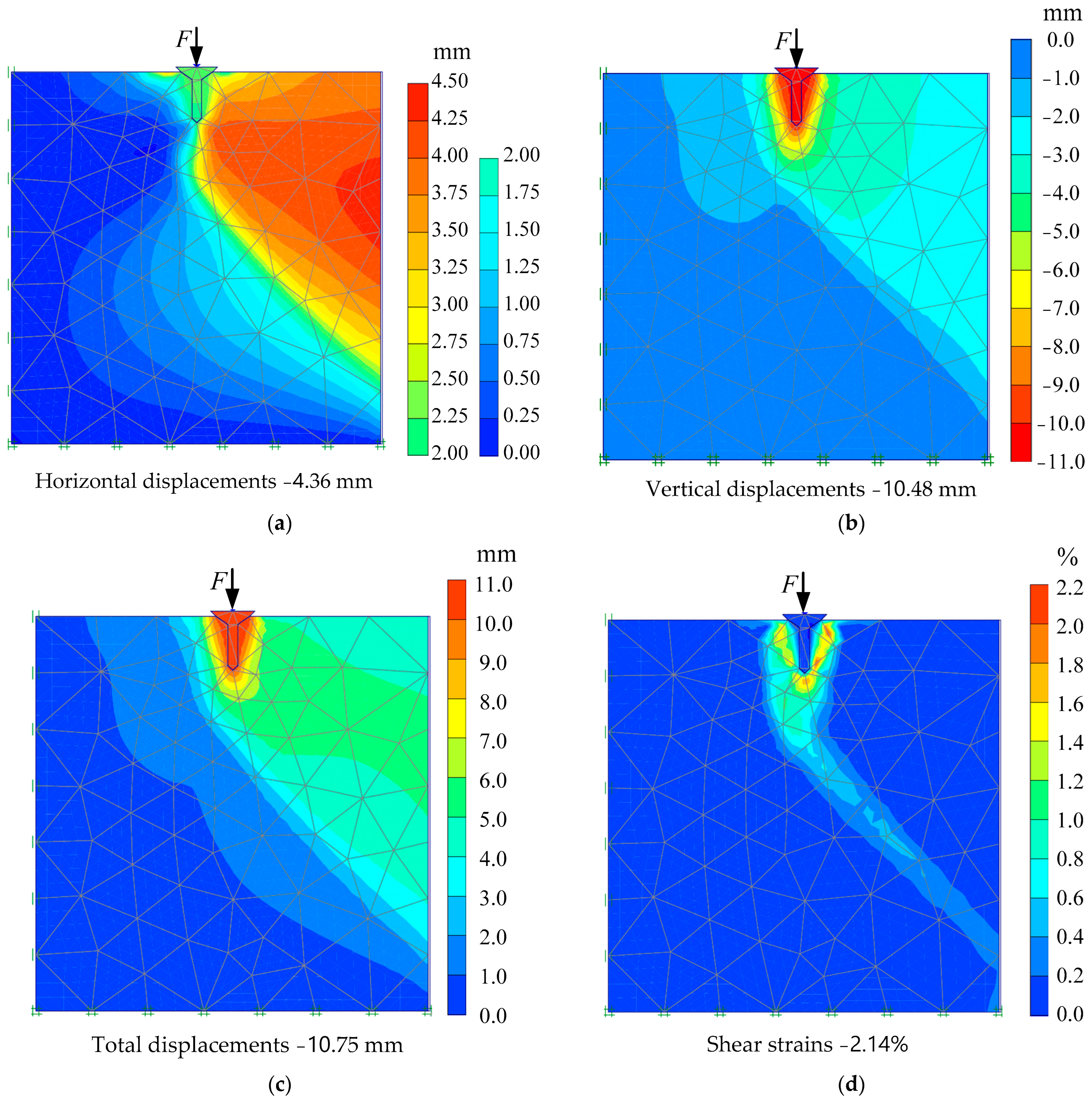
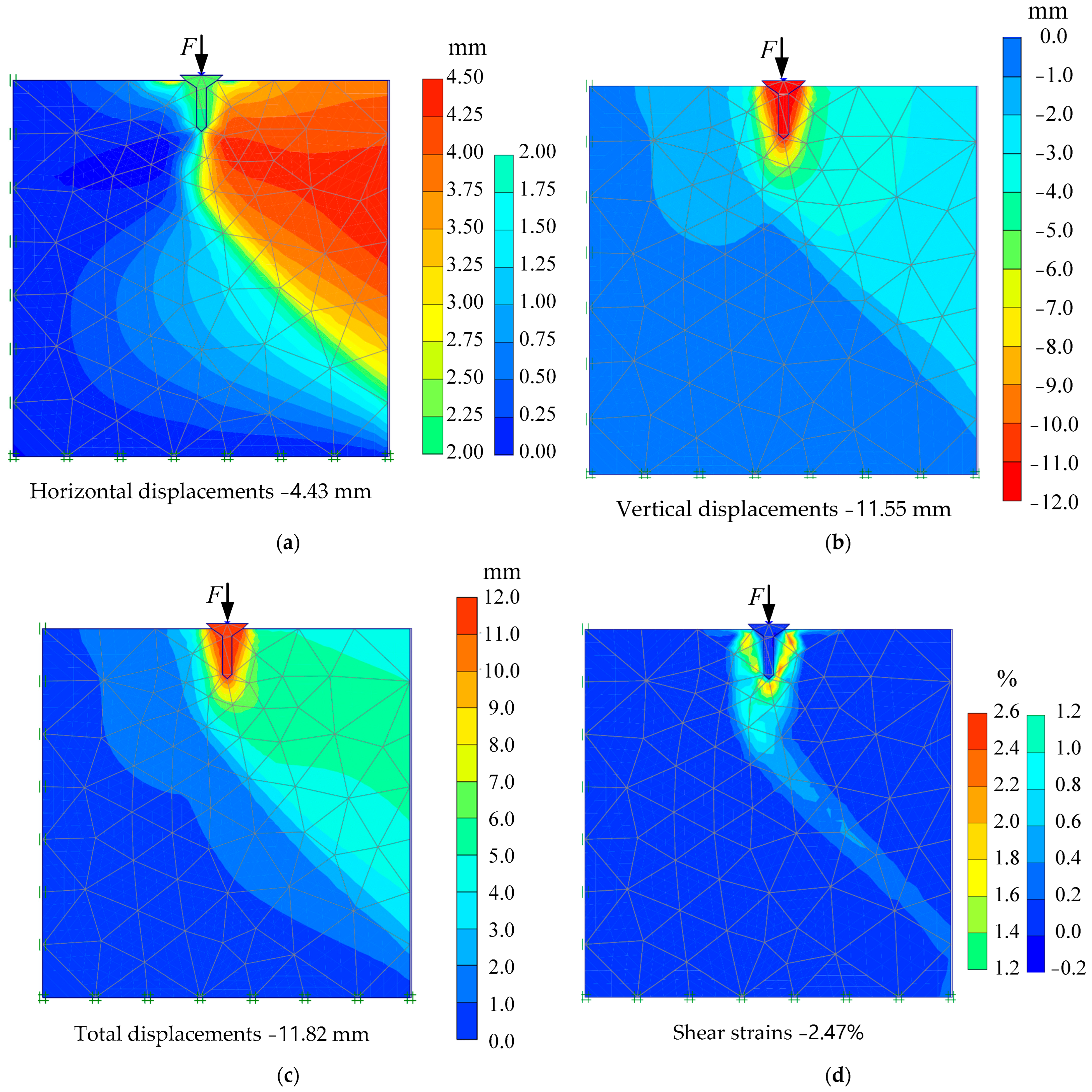
The geometry was defined based on the dimensions of the reduced-scale foundation, including the cone height, base diameter, and embedment depth in the soil. Numerical modeling was carried out for laboratory tests of a cone-top pile model, as well as an isolated shallow foundation. Loading was also simulated under 3, 6 and 9 mm/m horizontal soil displacement in the expandable box, as well as in the absence of horizontal soil deformations (
Figure 9,
Figure 10 and
Figure 11). The horizontal displacement of soils simulated a tension zone with the possible formation of cracks in it, and was achieved by displacement of the sections in the extendable stand to the above-mentioned values.
The soil domain was defined as large enough to minimize boundary effects, typically extending by 4–5 times the cone diameter in all directions, from the edge of the foundation. Vertical boundaries were fixed in the horizontal direction (roller boundaries) for zero horizontal displacement simulation, and with the possibility of subsequent movement of the right border to simulate soil deformation, while the bottom boundary was fully fixed in both directions, to simulate realistic soil confinement.
The soil was modeled using the Mohr–Coulomb model, appropriate for initial static loading conditions. The conical foundation was modeled as a non-porous, linear elastic volume, or as a rigid body, depending on the stiffness assumption. Material properties were defined using the appropriate Young’s modulus and Poisson’s ratio.
The mesh was generated using 15-node triangular elements, for higher accuracy. Local mesh refinement was applied in the vicinity of the cone–soil interface, especially around the tip and base edges, to capture stress concentration zones. Global mesh was set to medium or fine, depending on the convergence requirements.
Static loading was applied vertically at the top of the foundation, and incrementally, using phased construction stages, to simulate realistic loading behavior. The simulation results included settlement, vertical stress distribution, and plastic strain development in the surrounding soil. Contour plots and load–settlement curves were extracted to analyze the bearing behavior and validate against experimental results.
For isolated shallow (columnar) foundations, two static loading conditions were considered: without horizontal soil displacement and with horizontal displacement of the soil (ɛ = 3 mm). Simulation with greater horizontal soil displacement resulted in loss of bearing capacity of the foundation. These conditions and the modeling approach were described in detail in our previous study, which was published in [
9]. The modeling parameters were the same as in laboratory tests.
3. Results
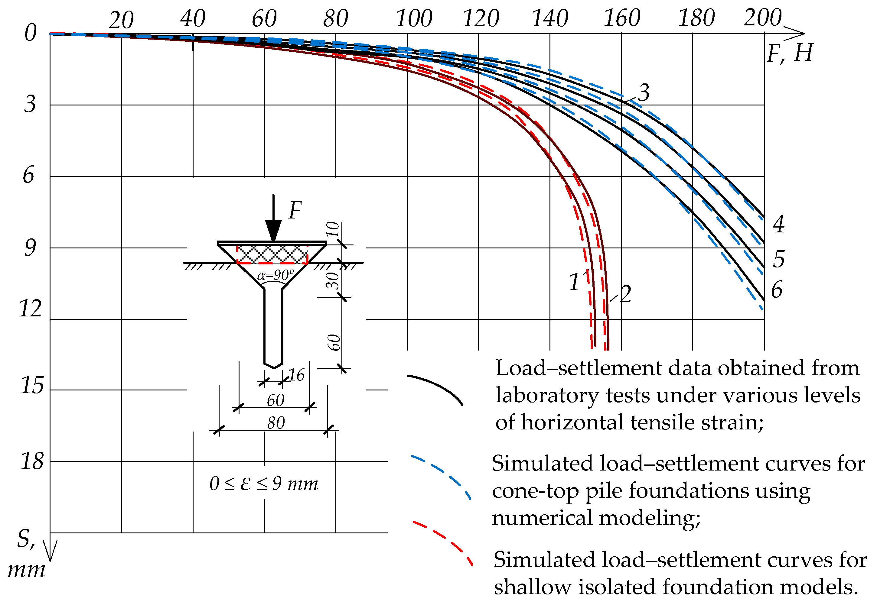
Laboratory tests of static loading under horizontal soil-displacement conditions have demonstrated an increase in settlement under horizontal forces, and hence a decrease in bearing capacity. However, conical models are superior in stability, due to the increase in cross-section of inverted conical models as they settle into the ground.
The applied load of 200 N with a simultaneous horizontal displacement of 9 mm/m led to the settlement of foundation models of up to 8 mm for the cone-top pile models, and up to 9 mm for the conical models described in the article [
9]. For isolated shallow foundations of a classical shape, with a constant cross-section, such a load with a horizontal displacement of 3 mm/m led to the bearing capacity failure of the foundations.
The results of laboratory modeling, presented in
Table 2, demonstrate a regular increase in the settlement of all types of foundations as horizontal tension strains in the soil increase. The cone-top pile foundation showed the least settlement under all loads, with values rising from 0.75 mm at 100 N (no strain) to 0.90 mm settlement at 9 mm/m strain, and from 8.06 mm settlement to 11.43 mm at 200 N loading. The conical foundation exhibited slightly higher settlements, increasing from 0.77 mm to 1.58 mm settlement at 100 N load and from 8.96 mm to 12.62 mm settlement at 200 N loading, with rising strain. The shallow isolated foundation, however, showed significantly larger settlements at equivalent loads, reaching 11.08 mm at only 3 mm/m strain and 150 N, emphasizing its lower stability under lateral soil deformation. These results highlight the superior performance of conical and cone-top foundations, particularly in resisting deformation under horizontal tension.
The numerical modeling results closely reflect the trends observed in laboratory tests, with slightly higher predicted settlements for the conical foundation under strain, as shown in
Table 3. For example, the numerical model of the conical foundation showed settlement increasing from 0.75 mm to 1.55 mm settlement at 100 N loading, and from 9.54 mm to 13.51 mm at 200 N, which is slightly greater than the experimental results. The cone-top pile foundation again showed the most stable performance, with settlements ranging from 0.75 mm to 0.90 mm at 100 N loading and from 8.40 mm to 11.82 mm at 200 N across increasing strains, closely matching the lab outcomes. The shallow isolated foundation also demonstrated poor performance in both simulations and experiments. Overall, numerical modeling validated the laboratory trends and confirmed that conical and cone-top foundations are more resilient under combined vertical load and lateral soil strain conditions.
In general, numerical modeling confirmed the results of laboratory tests with minimal deviations in settlement data under identical initial parameters of the soil and foundation models (
Figure 12). While isolated shallow foundations lost their load-bearing capacity after a load of 150 N, conical foundations continued to withstand the load even under horizontal soil displacements of up to 9 mm/m.
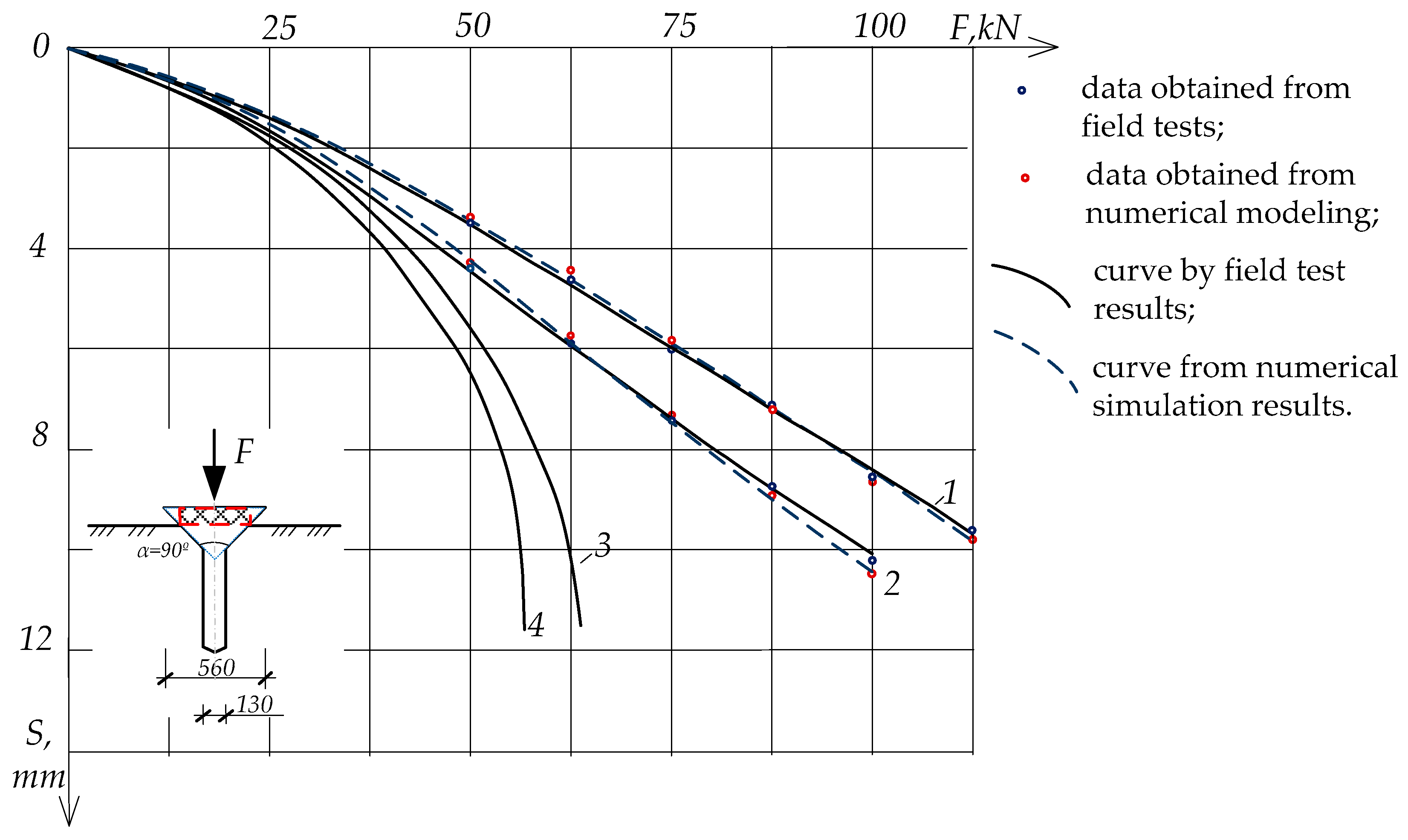
The results of the field studies are presented in
Table 4. Field tests were limited to an actual horizontal soil displacement of 2.7 mm, although they confirmed a higher bearing capacity, even compared to conical foundations [
9], which are also effective in areas of possible seismic activity and in mining areas (
Figure 13). In this case, the horizontal forces caused by horizontal tensile deformations of the soil mass can be similarly eliminated by installing a special sliding joint located between the conical foundations and the foundation structure.
The field test results demonstrate that all foundation types exhibited increased settlement with rising vertical loads, and the presence of horizontal tension strains in the soil (approximately 2.6–2.7 mm/m) consistently led to greater settlements, across the board. At a load of 100 kN, the cone-top pile foundation showed the highest settlement, of 10.09 mm under strain, compared to 8.52 mm without strain, representing an 18.4% increase. Similarly, the conical foundation experienced a 16.6% increase in settlement under strain, while the shallow isolated foundation showed a 19% increase at 75 kN. These results indicate that horizontal soil deformation significantly affects vertical settlement, with conical and cone-top pile foundations still performing better overall than shallow foundations, particularly under higher loads and strained conditions.
4. Design of a Reinforced-Concrete Conical Foundation
The industrial design of the proposed reinforced-concrete conical foundation block involves the development of a stable structure with an optimal selection of materials and reinforcement, to ensure high load-bearing capacity, especially under horizontal loads.
The conical foundation consists of a conical top and a pile-post. The inverted cone is the main load-bearing element, and its narrowed part serves as support and increases the area of contact with the ground. The base of the cone has an upper part which is wide and fixed at the level of the supporting part of the structure. The pile-post is under the inverted cone. The foundation structure is buried in the ground to a depth equal to approximately 3/4 of the radius of the cone base, to increase stability and resistance to horizontal soil movements. The design provides for dense reinforcement distributed throughout the volume of the conical block, which strengthens the foundation and ensures uniform distribution of loads.
4.1. Material and Reinforcement
To manufacture such a foundation block, heavy concrete of class B20 is used, which has high strength and resistance to loads, as well as durability under environmental conditions. Concrete must be frost-resistant and moisture-resistant, especially when laid in areas with high groundwater. High-quality concrete, in combination with reinforcement, protects the foundation from cracking and deformation, especially under the influence of dynamic and shear loads.
The selection of reinforcement is based on calculations of expected loads, including vertical and horizontal forces. Recommended reinforcement:
Vertical bars made of reinforcing steel grade A500C with a diameter of 16–25 mm. They are distributed along the height of the foundation and fixed at the base of the cone, and with a 20 cm overhang at the sharp end of the cone.
Transverse clamps for fixing vertical rods—made of reinforcing steel with a diameter of 8–12 mm with a step of 15–20 cm, decreasing as they approach the base of the cone.
Additionally, mesh reinforcement at the base of the cone increases shear resistance.
In the lower part of the foundation, where significant tensile forces occur, the reinforcement pitch is reduced, to compensate for the loads.
A denser mesh is used in the base to increase rigidity and stability under pressure on the ground. The width of the mesh side at the base of the cone is proposed to be 15–20 cm of A1 reinforcement—8–12 mm in diameter. This ensures sufficient reinforcement density to increase shear strength and prevent the concrete cracking under the load. In the case of increased loads or in the presence of aggressive conditions, the reinforcement pitch can be reduced to 100–150 mm, to strengthen the reinforced mesh of 10–16 mm.
For conical reinforced-concrete foundation blocks, the protective layer of concrete must ensure durability and protection of reinforcement from corrosion. When designing conical foundation blocks for industrial purposes, a protective layer of 40–50 mm is recommended, to ensure reliability and durability. If necessary, an anti-corrosion coating for reinforcement is used if the foundation is installed in an aggressive environment.
During the design, calculations are made for resistance to possible horizontal displacements and shear forces, which is especially important when using a cone with a deepened sharp end.
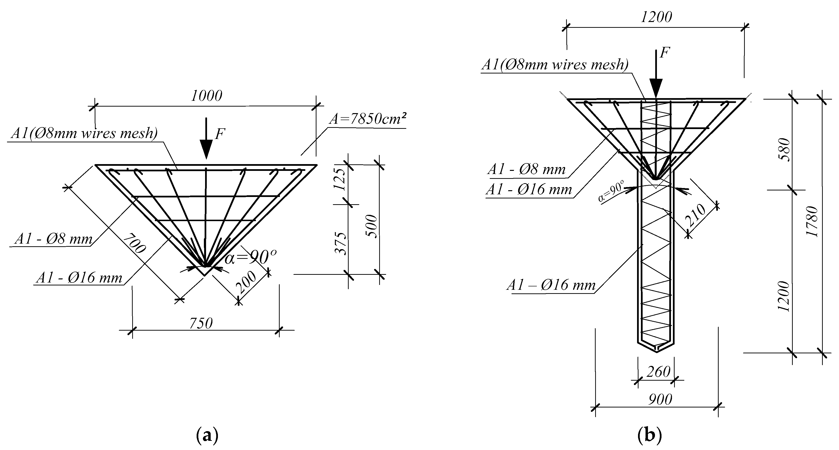
Figure 14 shows examples of reinforcement of a conical block having a height of 500 mm and with a cone base diameter of 1000 mm (
Figure 14a), as well as a conical foundation with a pile-stand with a total length of 1780 mm and a base diameter of 1200 mm (
Figure 14b). Such a project, of a reinforced-concrete conical foundation, ensures the stability of industrial equipment and structures, reducing deformation and increasing the service life of the system.
4.2. Calculation of Bearing Capacity of a Reinforced Cone-Top Conical Foundation
To calculate the bearing capacity of the conical pile foundation, the estimated load from a 2-story building measuring 12 by 24 m with a column grid of 6 by 6 m was considered, as well as the placement of cone-top pile foundations under load-bearing walls every 3 m. The estimated design load on each cone-top-pile block of the foundation was calculated to be 177.55 kN. The diameter of the base was selected based on calculations considering the loads on the structure, and was taken as 1200 mm.
Calculation of bearing capacity at the cone base was made according to the geometric characteristics in
Figure 14b. According to Terzagi’s bearing capacity formula for c-φ soil:
—Ultimate bearing capacity kN/m3;
—Contribution of soil cohesion to bearing capacity;
—Contribution from surcharge (vertical stress due to overlying soil at base depth);
—Contribution from unit weight of the soil acting directly under the base;
—Depth of the footing, 1.61 m;
—Width of the footing, the same as pile shaft diameter, 0.26 m;
—Unit weight of the soil, 21.2 kN/m3;
,
,
—Bearing capacity factors, which are dimensionless values that depend on the soil’s angle of internal friction (φ) and the shape of the foundation.
Note on net bearing capacity:
Allowable bearing capacity with FS = 3:
Base area: .
Applied pressure: .
312.3 kPa < 478.30 kPa safety is ensured. The cone base is safe under the applied load of 177.55 kN with a factor of safety of 3.
Allowable reserve capacity: .
Side friction resistance for the pile shaft Qs is calculated for using the α-method:
where the pile shaft friction area is A
s = π · D
pile · h
pile ≈3.14 · 0.26 · 1.2 = 0.98 m
2.
Total resistance = 271.8 kPa * 0.98 m2 + 19.11 kN = 285.47 kN capacity > 177.55 kN applied. Side friction-resistance safety is ensured. No extrusion is expected under this load, given the depth, cohesion, and effective surface contact.
It is assumed that the cone is a frustum, and so its lateral surface area is
where
—diameter of the top (smaller) base of the frustum;
—diameter of the bottom (larger) base of the frustum;
—vertical height of the frustum (not slant height);
l—slant height of the frustum;
—lateral surface area of the conical frustum.
Side friction on cone: .
Side resistance of the cone: .
Total side resistance of pile shaft and cone
Q = 19.11 + 17.28 = 36.39 kN. The final bearing capacity of the cone-top pile foundation, including contributions from base resistance and shaft friction, is presented in
Table 5.
The applied vertical stress 177.5 kN does not exceed the ultimate strength of the soil around the cone-top pile foundation block; therefore, no extrusion is expected under this load, given the depth, cohesion, and effective surface contact.
4.3. Settlement Estimation
Elastic settlement
in the case of saturated clayey soils:
s—elastic settlement of the foundation (m or mm);
q—uniform applied pressure/load on the foundation (kPa or N/m2);
B—width (or diameter) of the foundation in the direction of loading (m);
ν—Poisson’s ratio of the soil (dimensionless);
E—Young’s modulus (modulus of elasticity) of the soil (kPa or N/m2);
—influence factor (dimensionless), which depends on the shape and rigidity of the foundation, embedment depth, and type of load (values typically range from 0.8 to 1.2 for surface footings).
The following assumptions were made in the calculation: homogeneous, linearly elastic and isotropic soil; the foundation is flexible and round; the load is applied centrally and vertically; there are no time-dependent effects (i.e., it is instantaneous).
Consolidation Settlement
:
—primary consolidation settlement (m or mm);
—compression index (dimensionless), obtained from oedometer tests;
H—thickness of the compressible clay layer (m);
—initial void ratio of the soil (dimensionless);
—initial effective vertical stress in the soil layer before loading (kPa);
—increase in vertical stress, due to the applied load (kPa);
Then, the total settlement would be 64 mm.
It is assumed that consolidation occurs mostly under the cone-top, and 1.2 m (the same as the pile shaft length) was used as an approximation of this compressible zone beneath the loaded base—not the entire pile length. This is because the cone-top pile base sits at ≈1.61 m depth. The load is transferred downward, so stress dissipates mainly below the cone. The vertical extent of the pressure bulb under the base is the depth of soil significantly affected by the load. For shallow foundations or pile tips, this zone is roughly H = B… 2B, where B is a cone base diameter ≈ 0.85 m at the intersection with the ground. Using a vertical-stress distribution model (like Boussinesq or 2:1 spread), stress becomes negligible at 1.5 × B (≈1.2–1.3 m) below the base.
The vertical load of 177.55 kN acts on the upper inverted conical base, transferring stress to the surrounding soil. The load spreads along the side surface of the cone and the pile shaft, creating both side friction resistance and a downward base pressure. The applied vertical stress does not exceed the ultimate strength of the soil around the cone, so extrusion or local failure is excluded.
4.4. Installation Technology
Preliminary preparation of the foundation pit for deepening the cone with the appropriate foundation density and preparation of cone-shaped depressions for installing the precast concrete block is carried out. The opening angle of the conical top is usually 70–90°, to increase stability. Next, piles with a conical top are driven in. The total height of the foundation and the depth of deepening depend on the soil characteristics and the parameters of the above-ground structure. The advantages of the recessed foundation of the conical model are increased resistance to lateral and vertical loads, due to the installation depth. There is minimization of settlement and reduction of the risk of deformation, since the deepening to 3/4 of the height contributes to the uniform distribution of loads over the entire surface of the foundation. Good shear and displacement-resistance characteristics make it suitable for heavy industrial applications and difficult soil conditions.
5. Discussion
The results of this study clearly confirm that tapered foundations offer superior performance over flat or shallow counterparts of an equivalent base area. This is primarily due to increased side resistance and reduced stress concentration beneath the footing, as consistently demonstrated in both experimental and numerical models. These findings align with the conclusions of Keawsawasvong [
16], who emphasized that conical geometry enhances vertical load distribution and improves bearing capacity across a range of soil conditions. Likewise, Cassidy and Houlsby [
17] showed that in sandy soils, tapered profiles significantly reduce settlement by mobilizing broader failure surfaces, a principle that was validated in our cone-top pile test results.
The enhanced performance of the cone-top pile foundation—notably its lower settlement values and higher load tolerance—was further supported by Houlsby and Martin [
18], who demonstrated that deeper embedment and conical shaping improve undrained capacity in clays. In our study, the optimized embedment depth and cone base angle were crucial for maximizing soil resistance while preventing extrusion, particularly under increased vertical loading. Field observations confirmed that most consolidation and stress dissipation occurred within a depth of 1.2–1.3 m below the conical base, aligning well with theoretical stress-dispersion models and validating the assumed compressible zone used in our settlement calculations.
The beneficial influence of tapering and base roughness on bearing capacity was further supported by the findings of Kritesh et al. [
20], whose FELA-MARS model showed that roughened conical bases provide enhanced shear resistance and stress transfer. In our field tests, this translated to better stability of cone-top foundations even under significant horizontal tensile strains, which increased settlements by up to 19% for conventional foundations. The cone-top system, in contrast, maintained structural performance without approaching failure thresholds.
Recent data-driven studies, such as those by Nguyen Van et al. [
21] and Lai et al. [
22], have highlighted the impact of soil heterogeneity and anisotropy on the bearing behavior of conical footings. Although this study does not focus specifically on anisotropy, the robustness of the cone-top pile design across variable soil conditions supports their conclusion that such geometries perform reliably when soil strength varies with depth. The accuracy of our axisymmetric PLAXIS simulations, especially when refined around the cone–shaft interface, further supports the use of numerical modeling in predicting load-settlement behavior in complex soil profiles.
In terms of lateral stability, the present foundation design benefits from a key structural enhancement: the integration of a pile shaft into the conical base. This configuration not only provides deeper load anchorage, but also mobilizes additional shaft friction. While our focus was primarily on vertical loading, this concept draws direct relevance from Sivapriya and Gandhi [
24], who showed that piles embedded in sloping clay under lateral load exhibit distinct advantages in displacement control when designed for complex soil geometry. Therefore, the cone-top pile may offer increased resistance not only to vertical loading, but also to horizontal deformation in sloped or deformable terrains.
Furthermore, the inclusion of a rolling joint between the cone and superstructure enhances the system’s adaptability under horizontal soil movement. This innovation reflects similar design logic, as seen in Omarov et al. [
23], who showed that precast micropile systems with flexible joints maintain high performance in layered soils under both static and dynamic loading. Similarly, the rubber–steel interface in CHFRF foundations studied by Li et al. [
19] reinforces the value of introducing flexible connections to dissipate stress and reduce earth-pressure transfer during cyclic loading. While our system uses a rigid material rather than laminated rubber, the design intent remains similar: to isolate the structure from soil-induced tension strains and accommodate differential displacements.
An important aspect of this study involves quantifying the effect of horizontal tensile deformation of soils on foundation settlement, which is particularly relevant in conditions such as undermining, seismic loading, or lateral ground movement. The relationship between settlement under tensile soil strains (Su) and the baseline settlement without horizontal displacement (S
0) is described by the following empirical expression [
9]:
where
D is an empirical coefficient that characterizes the sensitivity of foundation settlement to horizontal tensile strain in the surrounding soil;
ɛ—horizontal tensile strains of the surface soils (tensile deformation), 0 ≤ ε ≤ 9·10−3 m;
Su—settlement with horizontal displacement of soils;
S0—settlement without horizontal displacement of soils.
The coefficient D in Equation (7) is an empirical, site-specific parameter that reflects the sensitivity of foundation settlement to horizontal tensile deformation of the surrounding soil. Its value depends on factors such as soil type, stress–strain characteristics, foundation geometry, and loading conditions. In this study, D was determined through curve fitting of laboratory and field test results for different types of conical foundations.
For practical applications, D can be estimated by calibrating finite element simulations with site-specific soil parameters, or by conducting reduced-scale physical model tests under controlled horizontal displacement conditions. In cases where testing is not feasible, practitioners may refer to published values of D from similar geotechnical conditions; however, such use should be approached with caution, due to the variability in soil behavior.
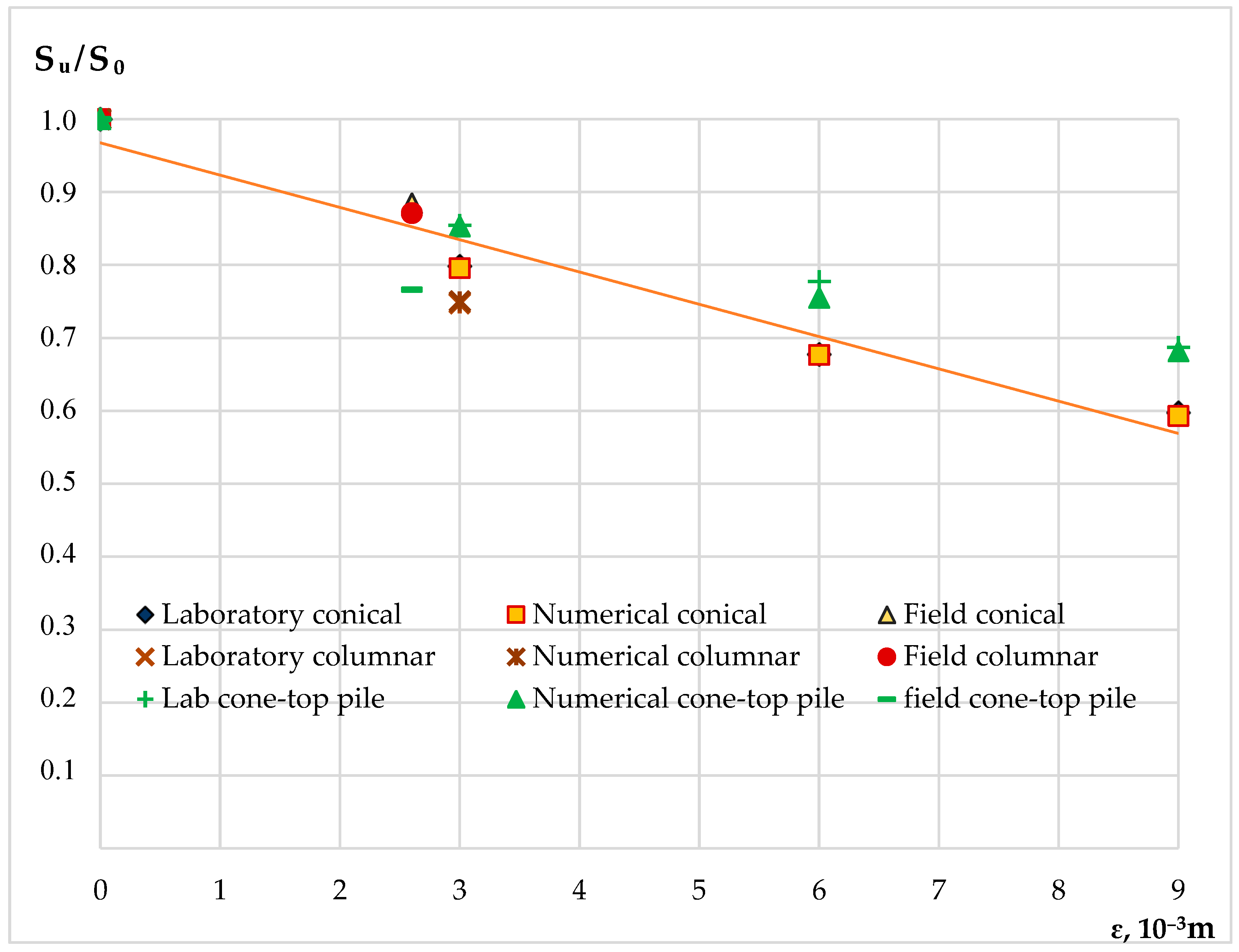
The
Sᵤ/
S0 relationship is illustrated in
Figure 15, which shows settlement trends for different foundation types under increasing horizontal tensile strain ε. Based on experimental and numerical results, the empirical coefficient
D—which represents the increase in settlement per unit of horizontal tensile strain—was found to be approximately 55 for standard conical foundation models and 41 for cone-top pile foundations under laboratory and simulated conditions. In contrast, field testing revealed
D = 44 for conical foundations and
D = 90 for cone-top pile foundations, indicating greater sensitivity to tensile soil deformation in real ground conditions for the latter.
These findings indicate that while cone-top pile foundations demonstrate lower baseline settlement, their response to horizontal tensile deformation may be more pronounced in certain field conditions, as reflected in the higher D value. However, this also suggests that cone-top pile systems are more sensitive to strain, but retain structural integrity and bearing capacity, without reaching failure. Importantly, if the value of D is known for a given soil-foundation system, this equation allows practitioners to estimate the expected increase in settlement due to horizontal soil strain, aiding in risk assessment and deformation control for critical infrastructure.
To support and complement these empirical findings, numerical simulations in this study were conducted using the Mohr–Coulomb model in PLAXIS 2D. This approach was selected for its simplicity and effectiveness in representing axisymmetric behavior under vertical loading. The model captured key deformation trends and stress concentration zones observed in the experimental tests. However, we acknowledge that more advanced constitutive models, such as the Hardening Soil or HS-Small models, could more accurately represent nonlinear stress–strain behavior, stiffness degradation, and small-strain effects in soft or structured soils. These models are particularly relevant for predicting long-term settlement or cyclic load response. Despite this, the current simulations provided sufficiently reliable results for comparative analysis between foundation types. For future studies, the use of advanced soil models is recommended for more precise prediction of absolute settlements and post-yield deformations, especially in heterogeneous or time-sensitive soil conditions.
Altogether, this study validates the cone-top pile foundation as a multi-functional system that unites the load-spreading efficiency of a conical footing with the deep resistance and lateral stiffness of a central pile. Compared to shallow or monolithic conical block foundations, it offers superior performance under both static vertical loads and lateral or tensile soil movements. Its ability to control settlement, prevent extrusion, and adapt to complex soil behavior makes it especially suitable for seismic zones, soft layered deposits, and undermined or anisotropic ground conditions.


