Article

Image Quality Assessment of Augmented Reality Glasses as Medical Display Devices (HoloLens 2)

1
Center for Ergonomics and Medical Engineering, FH Münster University of Applied Sciences, Bürgerkamp 3, 48565 Steinfurt, Germany
2
Institute of Psychology and Ergonomics, Technical University Berlin, Fasanenstraße 1, 10623 Berlin, Germany
*
Author to whom correspondence should be addressed.
Appl. Sci. 2025, 15(14), 7648; https://doi.org/10.3390/app15147648
Submission received: 5 June 2025 / Revised: 4 July 2025 / Accepted: 7 July 2025 / Published: 8 July 2025
(This article belongs to the Section Computing and Artificial Intelligence)

Abstract

Featured Application

This study allows clinical stakeholders to systematically assess the image quality of see-through augmented reality headsets in accordance with established medical display standards. The adapted methods support the integration of AR glasses, such as HoloLens 2, as medical display devices within clinical workflows. By quantifying essential image quality metrics, the proposed approach ensures that AR displays convey critical medical information with adequate fidelity for safe clinical use.

Abstract

See-through augmented reality glasses, such as HoloLens 2, are increasingly adopted in medical settings; however, their efficacy as medical display devices remains unclear, as current evaluation protocols are designed for traditional monitors. This study examined whether the established display-evaluation techniques apply to HoloLens 2 and whether it meets standards for primary and secondary medical displays. HoloLens 2 was assessed for overall image quality, luminance, grayscale consistency, and color uniformity. Five participants rated the TG18-OIQ pattern under ambient lighting conditions of 2.4 and 138.7 lx. Minimum and maximum luminance were measured using the TG18-LN12-03 and -18 patterns, targeting ≥ 300 cd/m2 and a luminance ratio ≥ 250. Grayscale conformity to the standard grayscale display function allowed deviations of 10% for primary and 20% for secondary displays. Color uniformity was measured at five screen positions for red, green, and blue, with a chromaticity limit of 0.01 for primary displays. HoloLens 2 satisfied four of the ten primary and four of the seven secondary overall-quality criteria, achieving a maximum luminance of 2366 cd/m2 and a luminance ratio of 1478.75. Grayscale uniformity was within tolerance for 10 of the 15 primary and 13 of the 15 secondary measurements, while 25 of the 30 color uniformity values exceeded the threshold. The adapted evaluation methods facilitate a systematic assessment of HoloLens 2 as a medical display. Owing to inadequate grayscale and color representation, the headset is unsuitable as a primary diagnostic display; for secondary use, requirements must be assessed based on specific application requirements.

1. Introduction

1.1. Use and Evaluation of Medical Display Devices

Imaging modalities such as radiography, computed tomography (CT), and magnetic resonance imaging are essential pillars of modern medicine. They provide critical information regarding the condition of bones, organs, and other tissues, which is vital for diagnosing and treating various diseases and injuries. Without these imaging procedures, accurate medical care would be unattainable in many domains. For physicians to effectively utilize the acquired image data, it must be presented on medical-grade display devices. The quality of these displays is paramount, as it influences the reliability of diagnostic and therapeutic decisions [1,2]. Subpar image quality can lead to misinterpretations and compromise patient safety [3]. Therefore, medical display devices must adhere to stringent standards across various technical parameters, including overall image quality, luminance, luminance-to-grayscale conformance, and color uniformity.
Standardized testing procedures were used to ensure compliance with these requirements. The overall image quality is typically assessed using a standardized test pattern comprising various elements, including fine line pairs, regions with different shades of gray, and text. An examiner evaluates whether these elements are recognizable and distinguishable on a display device [4,5,6].
Brightness is another critical parameter, defined by the luminance a display device can produce. Using a luminance meter, the examiner measures the minimum luminance of a black test pattern and the maximum luminance of a white test pattern [4,5,6].
Luminance-to-grayscale conformance refers to the relationship between the designated gray level of an image and the resulting luminance of the display device, thereby assessing the ability to discriminate between different shades of gray. This conformance is evaluated by measuring the luminance of multiple test patterns with graduated gray values. The measured values are compared to a standardized luminance curve to ensure that individual gray levels are distinguishable and consistently rendered across different display devices [4,5]. In the medical field, the gray scale standard display function (GSDF) has been established as a reference. This reference curve, defined in the Digital Imaging and Communications in Medicine (DICOM) guidelines, provides a uniform standard for accurate grayscale displays [7].
Finally, the color uniformity of the display device was assessed to ensure consistent color reproduction. The test measured the red, green, and blue color coordinates at multiple points on the screen [8], and the results were compared according to ISO standards [9]. This assessment evaluates whether the display device consistently reproduces colors uniformly across the entire screen area.
Manufacturers of medical display devices must demonstrate the performance of these parameters to secure approval as medical devices [8,10]. Post-deployment, healthcare facilities are mandated to conduct regular constancy tests to ensure continued image quality [6]. The stringency of display requirements varies according to their intended application. A fundamental distinction exists between primary and secondary display devices [4]. Primary displays, predominantly utilized in radiology, support diagnostic processes by presenting image data. These devices are subject to stringent requirements since diagnostic accuracy is heavily reliant on the quality of displayed images. Conversely, secondary display devices replicate confirmed findings and are not employed for initial diagnoses. They are used for purposes such as patient education, peer review, and preoperative planning. Since they only display image data previously assessed on primary displays, their requirements are less stringent.

1.2. Use of Augmented Reality Glasses as Medical Display Device

Beyond traditional display technologies, augmented reality (AR) glasses are becoming increasingly prevalent in the medical sector. These head-worn devices typically feature optically transparent see-through displays, enabling digital images or information to overlay the user’s view without obstructing environmental perception. The primary advantage of AR glasses lies in their capacity to seamlessly integrate virtual content into the user’s physical surroundings. In a medical setting, this integration facilitates the projection of medical images, markers, or instructions directly onto the field of view during patient care.
HoloLens 2 (Microsoft Corp., Redmond, WA, USA) is a premier AR device featuring a see-through display. It utilizes laser beam technology to generate images on a screen by sequentially moving three distinct lasers—red, green, and blue—line by line. By modulating the intensity of each laser beam, it can render a spectrum of colors and grayscale shades. This technology enables HoloLens 2 to project holographic images directly within the user’s visual field.
Figure 1 illustrates HoloLens 2 (left) and demonstrates its capability to display medical images within the user’s field of view (right).
HoloLens 2 has been evaluated and implemented in medical environments, particularly during surgical procedures [11]. Moreover, Southworth et al. [12] developed an AR system to assist minimally invasive cardiac surgeries by projecting three-dimensional electroanatomical heart maps onto a surgeon’s field of view to visualize cardiac conduction. Similarly, Balci et al. [13] utilized HoloLens 2 for preoperative planning in liver transplantation, converting CT image data into a three-dimensional liver model displayed within the surgeon’s field of view in the operating room. Both studies have demonstrated that AR significantly improves the precision and efficiency of surgical procedures.
The adoption of AR in surgery is increasing with the initial commercial applications already available. In surgical settings, overlaid images must precisely align with a patient’s actual anatomy, leading surgical research to frequently stress the spatial accuracy of virtual overlays [14,15,16]. Nevertheless, AR adoption in radiology—a field where image quality is critical—remains limited. This limitation may stem from the lack of appropriate testing methodologies to evaluate the image quality of AR glasses.
Existing test methods for AR glasses are not tailored for assessing medical devices [17,18] and do not establish acceptance criteria for medical display systems. Without such standards, the suitability and specific applications of AR glasses in medical settings remain uncertain. Furthermore, existing methods are designed exclusively for AR glasses with fixed pixel grids. However, it remains unclear whether these methods are applicable to HoloLens 2 [19,20,21].
In contrast, conventional medical display devices have established acceptance criteria. Nonetheless, it is uncertain whether these test methods can be adapted for AR glasses, such as HoloLens 2 [22,23]. Transferability would be beneficial, as manufacturers and healthcare providers already have experience with these procedures.
This study aimed to determine whether the established test methods for medical display devices are suitable for assessing the image quality of HoloLens 2. Additionally, we evaluated whether HoloLens 2 satisfies the criteria for primary and secondary display devices.

2. Materials and Methods

2.1. Materials

The image quality, luminance, luminance-to-grayscale conformity, and color uniformity of HoloLens 2 were evaluated using adapted test methods for medical display systems [4,5,6,7,9,24].
The overall image quality, luminance, and luminance-to-grayscale conformity were assessed using standardized test patterns from the American Association of Physicists in Medicine (AAPM), while the color uniformity was examined with red, green, and blue test patterns [7]. The materials used in this study are detailed in Table 1.
The luminance meter had a 15° field of view and a 1° measuring circle. All measuring devices were calibrated. Assessments were performed under controlled ambient conditions in a diagnostic room (2.4 lx) or an office environment (138.7 lx), representative of their respective areas [4,6].
Overall image quality was evaluated in both settings. To minimize ambient light interference, subsequent measurements were exclusively conducted in the diagnostic room. The ambient lighting levels were continuously monitored with an illuminance meter during all tests.

2.2. Methods

2.2.1. Evaluation of Overall Image Quality

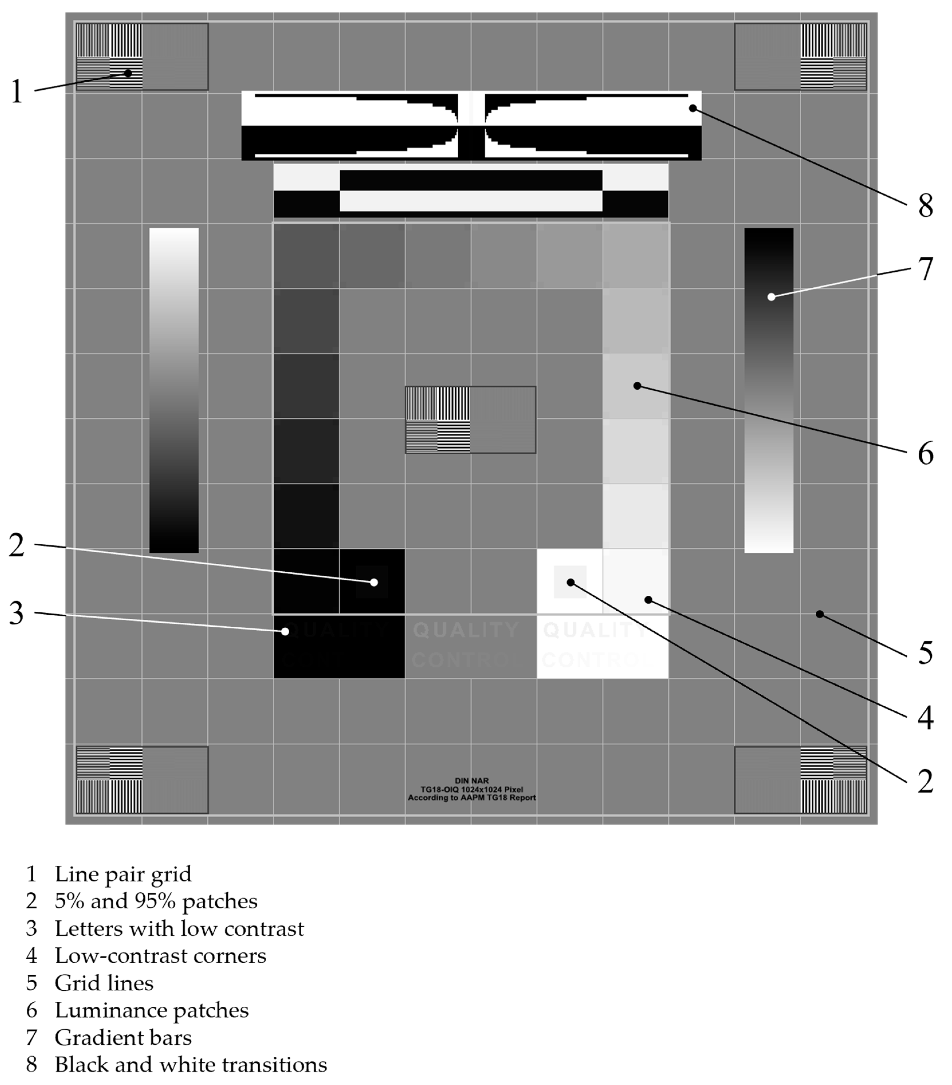
The overall image quality was evaluated with five test participants. These were medical engineers aged between 25 and 35 years with no visual deficits. The TG18-OIQ test pattern (Figure 2) was evaluated in both the diagnostic room and the office environment.
The participants viewed the test pattern displayed by HoloLens 2 from a distance of 30 cm. An examiner asked the control questions listed in Table 2.
For primary displays, all image elements must be discernible. In contrast, for secondary display devices, image elements 2 and 4 may be unclear, and the text “QUALITY CONTROL” is only legible in the white and gray field (image element 3) [6]. An image element is considered discernible or legible if the majority of participants confirm this in both settings.

2.2.2. Evaluation of Minimal and Maximal Luminance

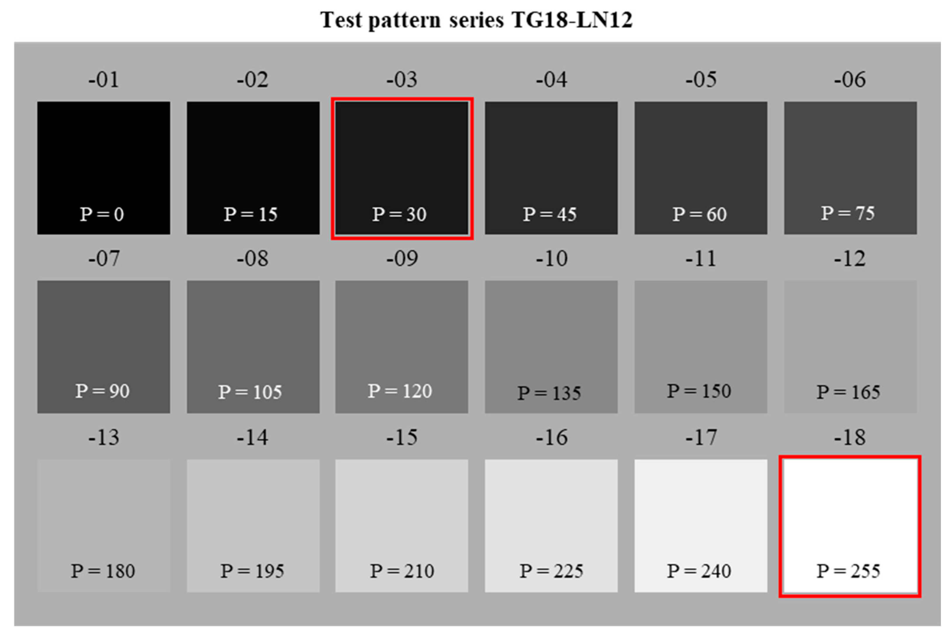
The minimum and maximum luminance were evaluated using the TG18-LN12 test series, which includes 18 grayscale images ranging from black to white (Figure 3). The black test pattern (-01) was used to determine the minimum luminance (Lmin), while the white test pattern (-18) was employed to determine the maximum luminance (Lmax) of conventional displays.
For a black image, the HoloLens 2 lasers are turned off, making the luminance of the two darkest images indeterminate. Consequently, the TG18-LN12-03 test pattern was used on HoloLens 2 to ascertain Lmin, and the white test pattern TG18-LN12-18 was utilized to determine maximum luminance. These test patterns are highlighted in red in Figure 3.
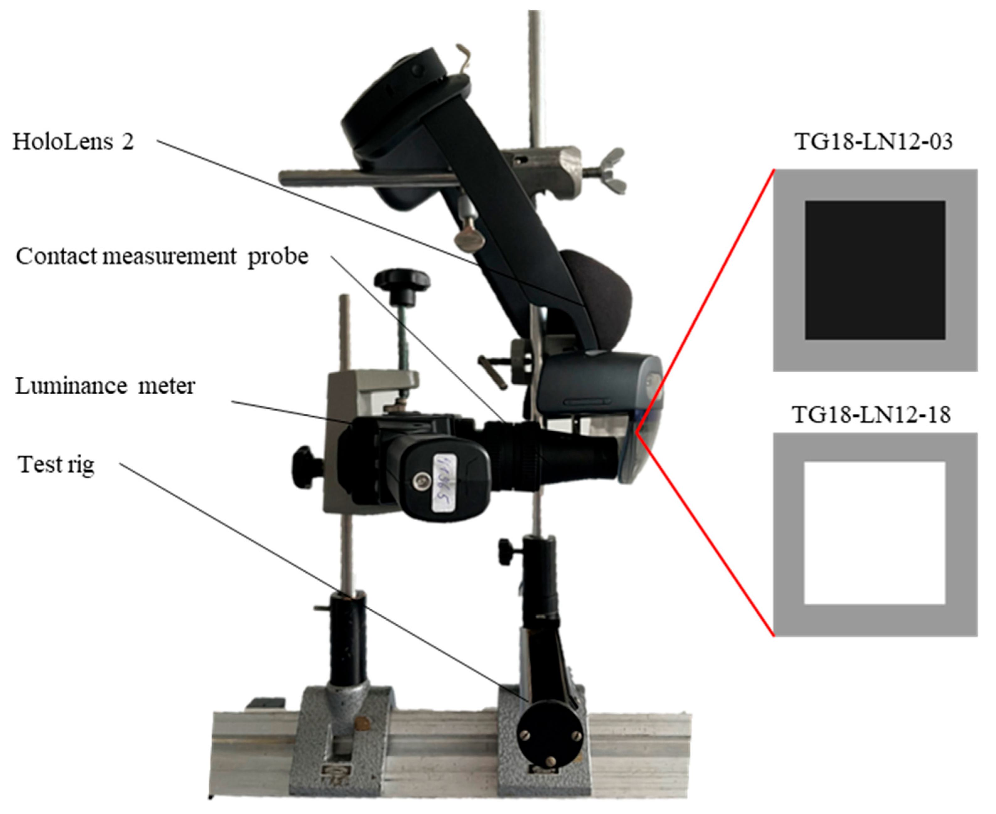
HoloLens 2 initially displayed the dark pattern, followed by the bright one. Both luminance values were measured using the contact method. The MAVO SPOT 2 luminance meter, equipped with the contact probe, was positioned vertically at the center of the screen. In the test setup illustrated in Figure 4, the measuring point is located near the eye position when wearing HoloLens 2.
For both primary and secondary medical display devices, Lmax must be ≥300 cd/m2, and the luminance ratio (Lmax/Lmin) must be ≥250 [4].

2.2.3. Evaluation of Luminance-to-Grayscale Conformance

To evaluate the luminance-to-grayscale conformity, the luminance levels of the 18 TG18-LN12 series test patterns (Figure 2) were measured and compared against the GSDF. Each test pattern corresponds to a specific gray level, defined by a digital input level (P) ranging from 0 (pattern -01) to 255 (pattern -18). The test patterns were uniformly distributed across this range to encompass the entire brightness spectrum.
Initially, the darkest (Lmin) and brightest (Lmax) test patterns were measured and assigned a just noticeable difference (JND) index following DICOM guidelines. This index accounts for the nonlinear perception of the eye and represents the number of brightness differences detectable by the human eye within a luminance range [24].
The difference between JNDmin (for Lmin) and JNDmax (for Lmax) indicates the number of gray levels the display device can distinguish. Subsequently, JND indices for all other test patterns were calculated using Equation (1):
J N D i = J N D m i n + P i     J N D m a x J N D m i n P m a x P m i n  
Here, JNDi represents the index to be determined, Pi denotes the digital input level of the test pattern, and Pmax or Pmin corresponds to the input levels of the brightest or darkest test patterns, respectively.
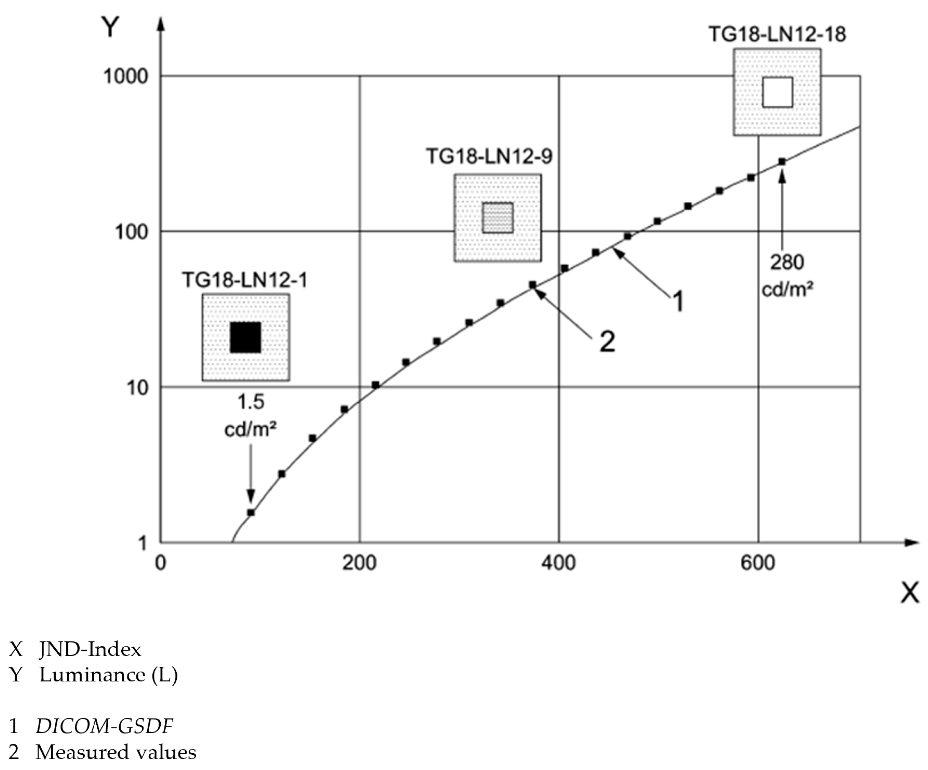
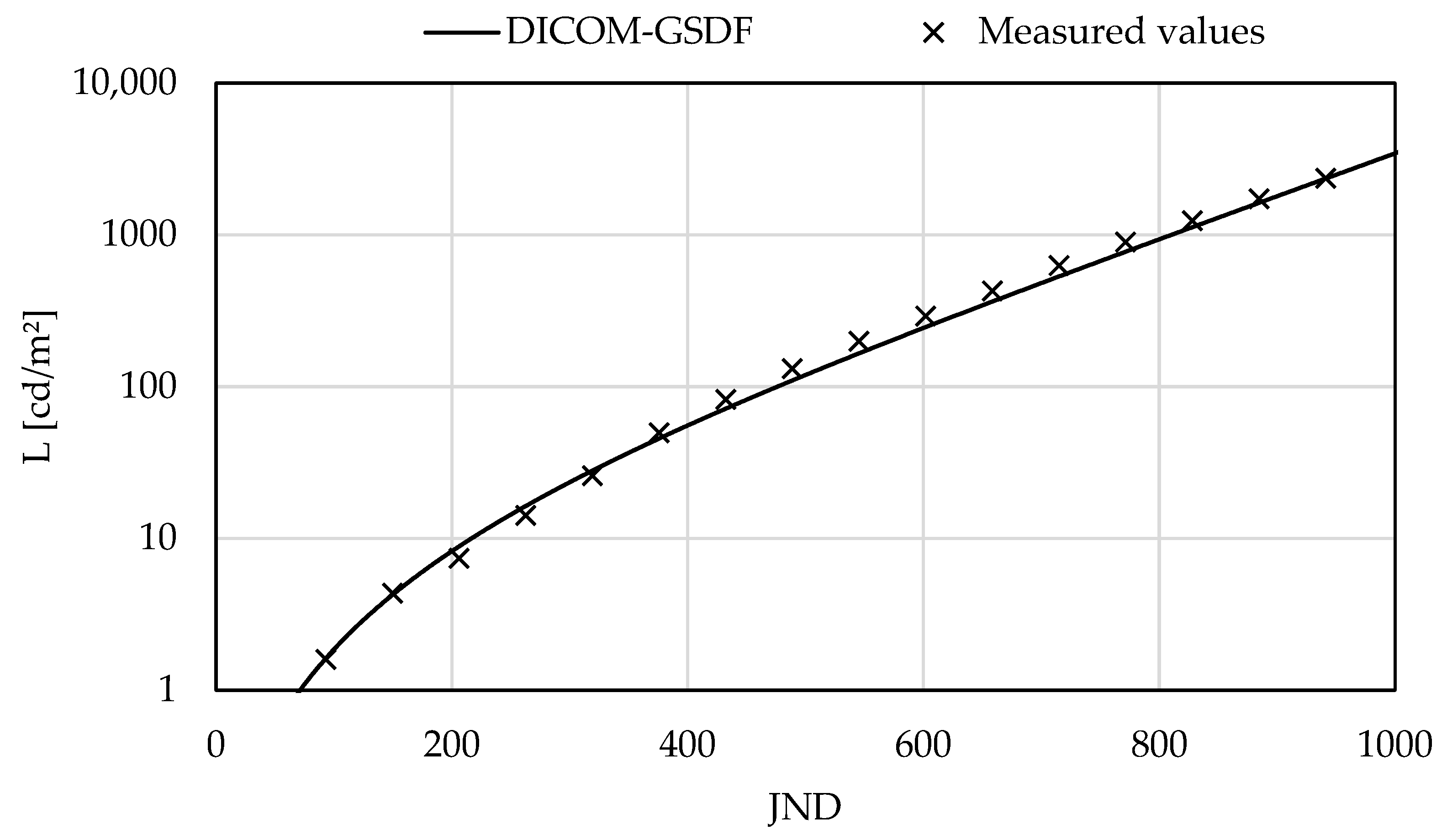
The measured luminance values were compared to those of the GSDF. In Figure 5, the measured luminance values are plotted on the y-axis against calculated JND indices on the x-axis.
To assess whether transitions between individual gray levels are perceived uniformly, the luminance response (ΔL/L) was calculated. This metric quantifies the brightness difference between two successive test patterns based on their mean luminance and the difference in their JND indices. The calculations followed Equation (2),
L L = 2   L i L i 1 L i + L i 1   J N D i J N D i 1
where Li and Li−1 denote the luminance values of two consecutive test patterns, while JNDi and JNDi−1 represent their respective indices.
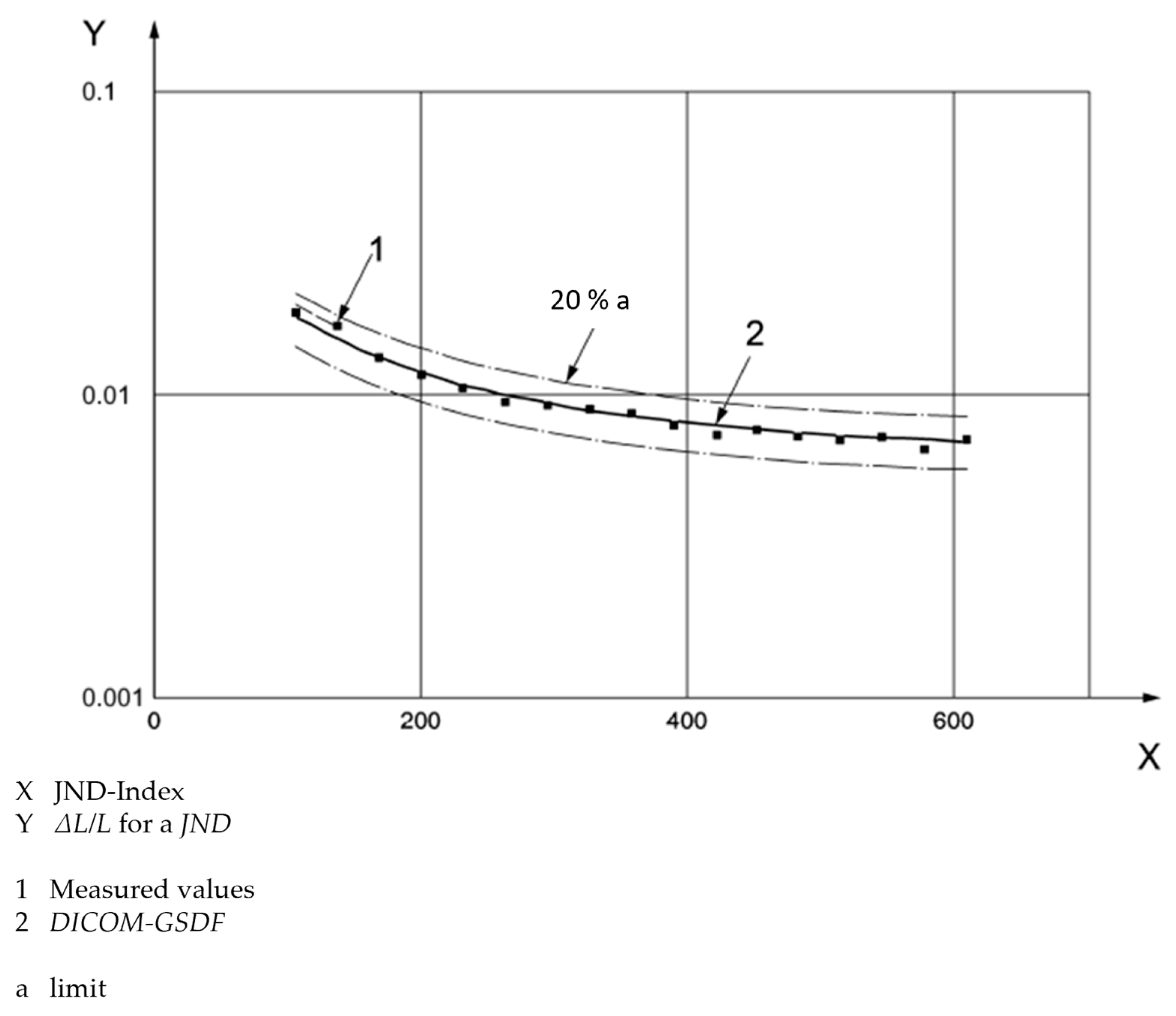
The luminance response of the display device was compared to the GSDF, as plotted in another graph. In Figure 6, the calculated contrast response is shown on the y-axis, plotted against the JND indices.
For primary displays, a maximum deviation of 10% from the GSDF contrast response is permissible, while secondary displays may diverge by up to 20% from the GSDF [4]. Because HoloLens 2 does not produce measurable luminance for entirely black images, measurements were limited to test patterns TG18-LN12-03 through TG18-LN12-18 (Figure 3). Luminance values were recorded following the procedure detailed in the previous section.

2.2.4. Evaluation of Color Uniformity

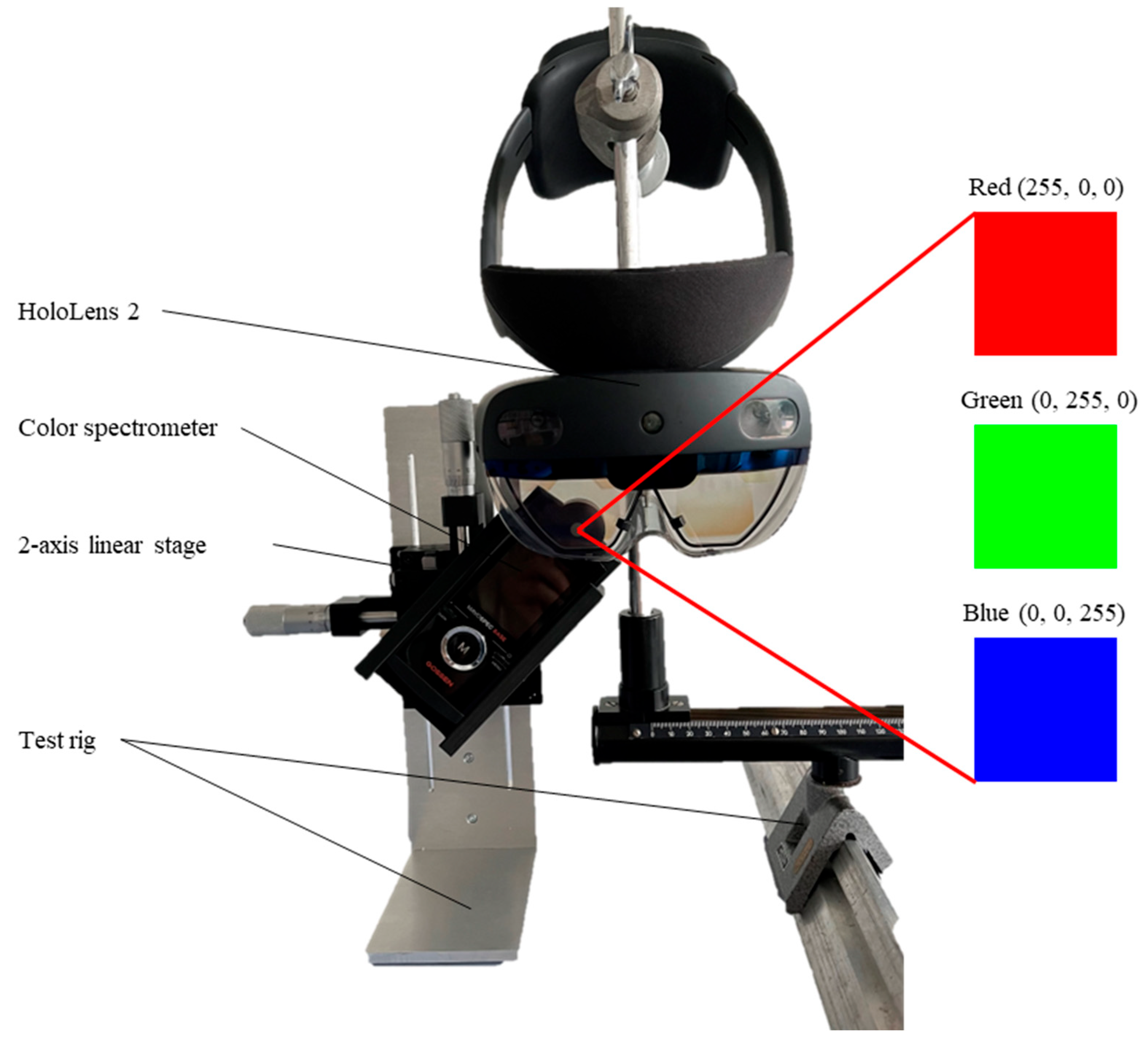
Color uniformity refers to the ability of a display to consistently render color tones across different screen areas. To evaluate color uniformity, monochromatic test patterns in red (255, 0, 0), green (0, 255, 0), and blue (0, 0, 255) were employed [8]. During assessment, these patterns were displayed on HoloLens 2, and their color coordinates (u′, v′) were measured at various locations using a color spectrometer (MAVOSPEC BASE). Measurements were taken at five positions: top left, top right, center, bottom left, and bottom right [9].
For these measurements, the color spectrometer was centrally positioned and vertically aligned with the HoloLens 2 screen, and a two-axis linear stage facilitated movement among the five measurement points. The test setup is illustrated in Figure 7.
The color coordinates for each measurement point were compared in pairs. The deviations between the color coordinates (u′, v′) were calculated using Equation (3),
u v = ( u 1 u 2 ) 2 + ( v 1 v 2 ) 2
where u1, v1 and u2, v2 represent the coordinates of two measurement points and Δuv′ indicates the distance between them.
For primary display devices, the maximum distance between color coordinates must not exceed 0.01. No quantitative criteria are defined for secondary displays [4].

3. Results

3.1. Evaluation of the Overall Image Quality

The participants’ visibility ratings for each image element in both environments are presented in Table 3.
All participants identified high-contrast line pairs (image element 1), grid lines (image element 5), and black-and-white transitions (image element 8) in both the diagnostic room and office. The text “QUALITY CONTROL” was completely legible in the white and gray boxes for three participants in each environment. However, it was not adequately legible in the black box (image element 3). None of the participants detected the 5% and 95% patches (image element 2), four low-contrast corners (image element 4), or the gradient bars (image element 7). In the diagnostic room, 14–15 of the 16 luminance patches could be distinguished; in the office, 13–15 could be distinguished (image element 6). No systematic differences were detected between the two environments.
HoloLens 2 fulfills four of the ten criteria for primary display devices and four of the seven criteria for secondary display devices.

3.2. Evaluation of Minimal and Maximal Lumnance

The luminance of HoloLens 2 ranges from a minimum of 1.6 cd/m2 to a maximum of 2366 cd/m2, resulting in a luminance ratio (Lmax/Lmin) of 1478.75. Consequently, HoloLens 2 meets the requirements for both primary and secondary display devices.

3.3. Evaluation of Luminance-to-Grayscale Conformance

Figure 8 illustrates the measured luminance of HoloLens 2 for test patterns TG18-LN12-03 through TG18-LN12-18 compared with the GSDF.
Comparing these measurements to the GSDF reveals deviations from the reference curve. Specifically, the luminance values for test patterns TG18-LN12-03 and TG18-LN12-04 align with the GSDF, while those for TG18-LN12-05 to TG18-LN12-07 fall below the reference. Starting with TG18-LN12-08, HoloLens 2 exhibits higher luminance values than the GSDF specifications.
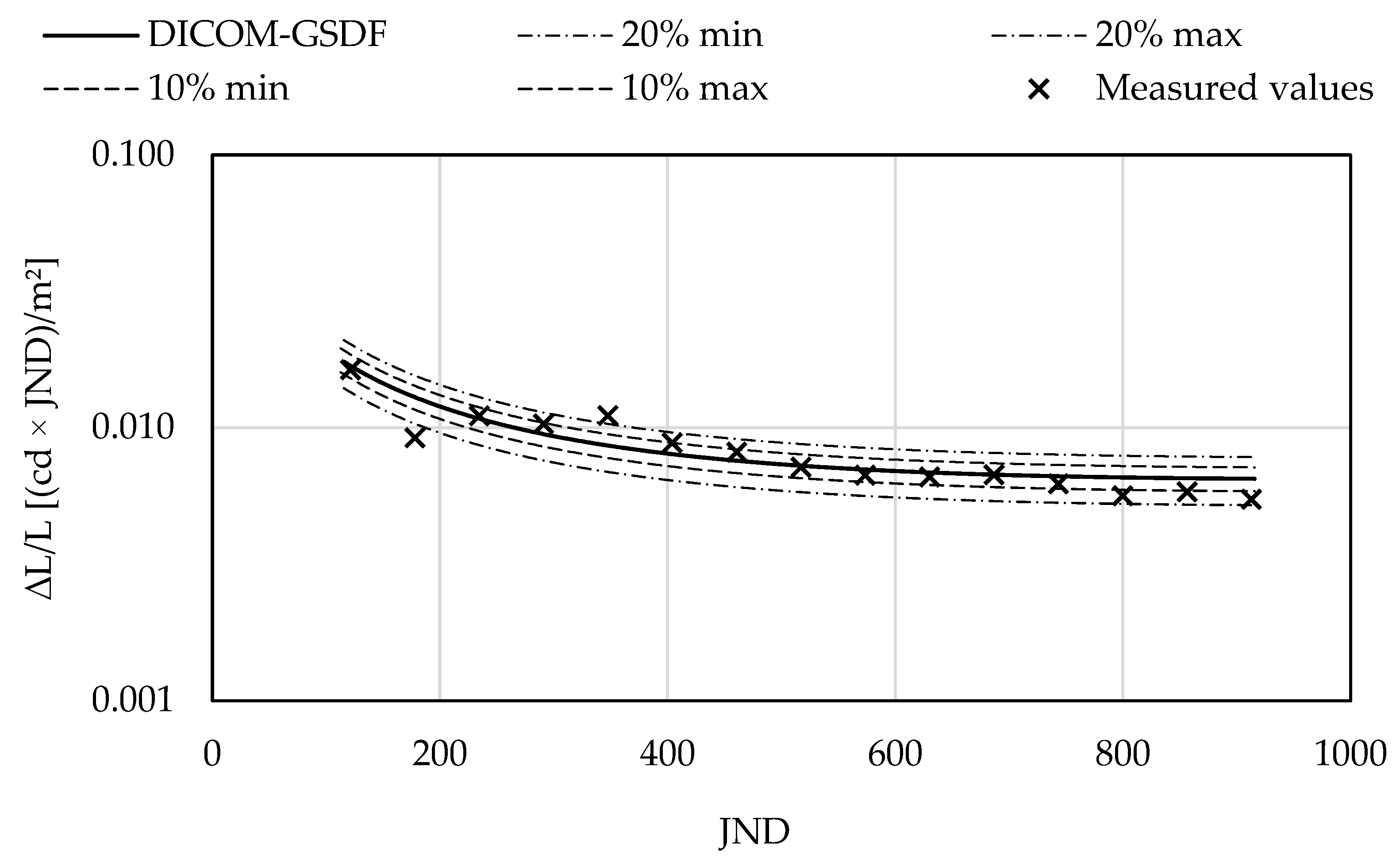
Figure 9 compares the luminance response of HoloLens 2 with the contrast response of the GSDF.
In the JND range up to 350, two measurements exceed the permissible deviation for secondary display devices. The deviations beyond the acceptable limits for primary display devices occur in the JND range starting from 750. Among the 15 measurements, 10 fall within the tolerance range for primary display devices, and 13 satisfy the criteria for secondary display devices.

3.4. Evaluation of the Color Uniformity

The color-rendering results for red, green, and blue are presented in Table 4. Value pairs with color coordinate distances exceeding 0.01 are highlighted in red, while those within acceptable distances are marked in green.
In the red test pattern, only the value pair between the center and bottom right demonstrated acceptable distances. Similarly, in the green test pattern, only the pair between the center and bottom left met the requirement. The blue test pattern showed three value pairs with acceptable distances. Overall, 25 out of 30 value pairs surpassed the tolerance threshold. Therefore, HoloLens 2 does not satisfy the criteria for primary display devices. There are no established quantitative standards for value pair spacing in secondary display devices.

4. Discussion

4.1. Evaluation of the Overall Image Quality

This study is the first to evaluate the overall image quality of HoloLens 2 in a medical context based on participants’ subjective ratings, allowing users to directly assess the perceptibility of image elements.
The findings reveal that HoloLens 2 struggles to display dark gray shades effectively. Participants had difficulty distinguishing the first two luminance surface elements (image element 6). However, upon distinguishing between the first and third, as well as the second and third, surface elements were generally achievable. Additionally, participants noted perceiving an edge in the black area of the gradient bars (image element 7).
Zhao et al. [25] evaluated the image quality of HoloLens 2 and compared it to AR glasses utilizing the organic light-emitting diode (OLED) technology. Their findings revealed deficiencies in contrast display within dark image regions and inadequate differentiation of highly bright images. Nonetheless, these issues were not identified in the present study.
Erickson et al. [26] investigated the influence of ambient illumination on the contrast displays of both HoloLens and HoloLens 2 across environments with illuminance levels ranging from 0 to 20,000 lx. They reported that contrast—and consequently image quality—diminished in brightly lit settings.
Conversely, ambient lighting had minimal effect on the visibility of image elements in this study. Participants performed similarly in both the examination room and office, with only two individuals showing a decreased ability to discern luminance surface elements. Notably, the office illuminance (138.7 lx) was markedly lower than that in Erickson et al.’s [26] study. Therefore, the visibility of image elements in exceedingly bright environments, such as operating rooms, warrants further investigation.

4.2. Evaluation of Luminance and Luminance-to-Grayscale Conformance

With a maximum luminance of 2366 cd/m2 and a luminance ratio of 1478.75, HoloLens 2 clearly surpasses the requirements for primary and secondary display devices. However, HoloLens 2 lacks an absolute black point owing to its laser beam technology, which can present significant challenges for diagnostic applications.
Moreover, the contrast response of HoloLens 2 occasionally showed unacceptable deviations from the GSDF, potentially impairing the perception of subtle contrast differences and thereby complicating diagnostic tasks.

4.3. Evaluation of Color Uniformity

The color uniformity evaluation revealed that HoloLens 2 inconsistently displayed colors across different display areas. In 25 out of 30 assessments, HoloLens 2 surpassed the maximum permissible deviation for primary display devices, demonstrating its current unsuitability for medical applications dependent on color-coded visualization.
Laudien et al. [27] evaluated the color uniformity of HoloLens 2 using nine distinct colors and found that color homogeneity was generally maintained under optimal conditions. Nevertheless, color shifts occurred at varying viewing angles. Aligning with our results, Laudien et al. [27] noted that blue remained the most stable color.
Similarly, Johnson et al. [28] and Zhao et al. [25] detected luminance inhomogeneities across multiple display points. Johnson et al. [28] applied a software-based flat field correction technique, which enhanced homogeneity but diminished the overall screen luminance.

4.4. Limitations

A key limitation of this study is the fact that some of the parameters affecting display image quality were not examined, such as pixel errors, image artifacts, and temporal responses. However, these factors are irrelevant to HoloLens 2 owing to its laser beam technology.
HoloLens 2 produces images by continuously scanning a display with a laser, and the lack of a fixed pixel grid prevents pixel errors present in conventional displays. Additionally, static image artifacts (ghost images) are absent because the projection is continuously updated.
To evaluate the temporal response of conventional display devices, their rise and fall time constants are measured to determine temporal resolution. In HoloLens 2, image content is generated through laser sweeps, with lasers activated and deactivated between pixels. Consequently, the rise and fall time constants are several orders of magnitude shorter than the laser sweep duration. Thus, temporal resolution depends on the laser scan frequency, making it critical for establishing the temporal resolution of HoloLens 2. The manufacturer specifies a scan frequency of 120 Hz, sufficient to display 60 contrasts per second. This exceeds the temporal resolution of the human visual system within the field of view of HoloLens 2 across all common scenarios, leading us to conclude that the temporal resolution is adequate [29].
Additionally, the luminance of HoloLens 2 is highly angle-dependent owing to its laser beam projection technology. This study selected a measurement angle of 90°, which ideally aligns with the user’s eye position when wearing HoloLens 2. This angle is also used in conventional medical display systems; therefore, the corresponding requirements are tailored to this orientation. Existing methods address the angular dependence of see-through displays using light-emitting diode (LED) or organic light-emitting diode (OLED) technologies [30]. However, their application in the medical field remains unestablished and necessitates specialized measurement equipment. Moreover, it remains unclear whether these methods are applicable to see-through displays that utilize laser beam projection technology. Future research should, therefore, focus on evaluating the angle dependence of HoloLens 2.
A further limitation concerns the approach used to assess color uniformity. In this study, measurements were performed by translating the measurement device across the display while maintaining a fixed orientation. Although this method enhances comparability with conventional display devices, it does not fully emulate the viewing conditions experienced when wearing AR glasses. A more realistic approach would involve positioning the measuring device at the typical eye level and tilting it to simulate various viewing angles. Future investigations should adopt this alternative method to more accurately capture user-perceived color shifts.
Finally, this study did not analyze the spectral emission characteristics of HoloLens 2. The device utilizes an RGB laser system with discrete wavelengths, potentially including emissions in the eye-damaging blue light spectrum. Given that prolonged use may be necessary for medical applications, future studies should address these potential risks.

5. Conclusions

This study systematically evaluated the image quality of HoloLens 2 as a representative example of AR glasses with see-through displays for medical applications. To achieve this, evaluation methods suitable for conventional monitors were adapted for HoloLens 2. The results revealed deficiencies comparable to those observed in test methods specifically developed for AR glasses in the non-medical sector. Employing the selected methodologies facilitated the assessment of HoloLens 2 against the established criteria for medical display devices.
Overall, this study reveals that HoloLens 2 surpasses the requirements for luminance and luminance ratio. Nonetheless, it shows shortcomings in rendering dark grayscales and in certain instances deviates significantly from the contrast response of the GSDF. Additionally, the color representation of HoloLens 2 lacks consistency. Therefore, HoloLens 2 is currently unsuitable as a primary diagnostic display device. Future investigations should consider software-based solutions to mitigate these limitations.
These shortcomings are deemed less critical when the device functions as a secondary display. However, the requirements for each application must be assessed individually. The preliminary market approvals for HoloLens 2 in medical applications corroborate this evaluation [31,32,33].

Author Contributions

Conceptualization, S.K. and S.S.; methodology, S.K. and S.S.; investigation, S.K.; data curation, S.K.; writing—original draft preparation, S.K.; writing—review and editing, S.S. and C.B.; visualization, S.K.; supervision, C.B.; project administration, S.S. All authors have read and agreed to the published version of the manuscript.

Funding

This study was funded by apoQlar GmbH.

Institutional Review Board Statement

The presented work does not include any studies on humans or animals. Due to the design of the study, a formal vote by an ethics committee was not required. The observations carried out by the participants do not pose any hazards that increase the general risk to the lives of the persons concerned. All participants gave informed consent to participate in the study.

Informed Consent Statement

Informed consent was obtained from all participants involved in the study.

Data Availability Statement

The data presented in this study are available on request from the corresponding author.

Conflicts of Interest

The authors declare no conflicts of interest. The funders had no role in the design of the study; in the collection, analysis, or interpretation of data; in the writing of the manuscript; or in the decision to publish the results.

References

  1. Ackerman, S.J.; Gitlin, J.N.; Gayler, R.W.; Flagle, C.D.; Bryan, R.N. Receiver operating characteristic analysis of fracture and pneumonia detection: Comparison of laser-digitalized workstations and conventional analog radiographs. Radiology 1993, 186, 262–268. [Google Scholar] [CrossRef] [PubMed]
  2. Scott, W.W.; Bluemke, D.A.; Mysko, W.K.; Weller, G.E.R.; Kelen, G.D.; Reichle, R.L.; Weller, J.C.; Gitlin, J.N. Interpretation of emergency department radiographs by radiologists and emergency medicine physicians: Teleradiology workstation versus radiograph readings. Radiology 1995, 195, 223–229. [Google Scholar] [CrossRef] [PubMed]
  3. Butt, A.; Mahoney, M.; Savage, N.W. The impact of computer display performance on the quality of digital radiographs: A review. Aust. Dent. J. 2012, 57, 16–23. [Google Scholar] [CrossRef] [PubMed]
  4. Samei, E.; Badano, A.; Chakraborty, D.; Compton, K.; Cornelius, C.; Corrigan, K.; Flynn, M.J.; Hemminger, B.; Hangiandreou, N.; Johnson, J.; et al. Assessment of display performance for medical imaging systems: Executive summary of AAPM TG18 Report. Med. Phys. 2005, 32, 1205–1225. [Google Scholar] [CrossRef] [PubMed]
  5. IEC 62563–1:2009+A1:2016+A2:2021 CSV; Medical Electrical Equipment—Medical Image Display Systems—Part 1: Evaluation Methods. VDE VERLAG GmbH: Berlin, Germany, 2021.
  6. DIN 6868-157:2022; Image Quality Assurance in Diagnostic Xray Departments—Part 157. X-ray Ordinance Acceptance and Constancy Test Image Display Systems in Their Environment. Beuth Verlag GmbH: Berlin, Germany, 2022.
  7. NEMA PS 3.14-2006; Digital Image Communications in Medicine (DICOM)—Part 14: Grayscale Standard Display Function. National Electrical Manufactures Association (NEMA): Rosslyn, VA, USA, 2006.
  8. US Food and Drug Administration (FDA). Display Devices for Diagnostic Radiology—Guidance for Industry and Food and Drug Administration Staff; FDA: Silver Spring, MD, USA, 2022. Available online: https://www.fda.gov/media/95527/download (accessed on 2 June 2025).
  9. ISO/CIE 11664-5:2016; Colorimetry—Part 5: CIE 1976 L*u*v* Colour Space and u′, v′ Uniform Chromaticity Scale Diagram. International Organization for Standardization (ISO): Genf, Switzerland, 2016.
  10. European Commission. Regulation (EU) 2017/745 of the European Parliament and of the Council of 5 April 2017 on medical devices, amending Directive 2001/83/EC, Regulation (EC) No 178/2002 and Regulation (EC) No 1223/2009 and repealing Council Directives 90/385/EEC and 93/42/EEC. Off. J. Eur. Union. 2017, 117, 1–175. [Google Scholar]
  11. Palumbo, A. Microsoft HoloLens 2 in Medical and Healthcare Context: State of the Art and Future Prospects. Sensors 2022, 22, 7709. [Google Scholar] [CrossRef] [PubMed]
  12. Southworth, M.K.; Silva, J.N.A.; Blume, W.M.; Van Hare, G.F.; Dalal, A.S.; Silva, J.R. Performance evaluation of mixed reality display for guidance during transcatheter cardiac mapping and ablation. IEEE J. Transl. Eng. Health Med. 2020, 8, 1900810. [Google Scholar] [CrossRef] [PubMed]
  13. Balci, D.; Kirimker, E.O.; Raptis, D.A.; Gao, Y.; Kow, A.W.C. Uses of a dedicated 3D reconstruction software with augmented and mixed reality in planning and performing advanced liver surgery and living donor liver transplantation (with videos). Hepatobiliary Pancreat. Dis. Int. 2022, 21, 455–461. [Google Scholar] [CrossRef] [PubMed]
  14. Andersen, D.; Popescu, V.; Cabrera, M.E.; Shanghavi, A.; Mullis, B.; Marley, S.; Gomez, G.; Wachs, J.P. An Augmented Reality-Based Approach for Surgical Telementoring in Austere Environments. Mil. Med. 2017, 182, 310–315. [Google Scholar] [CrossRef] [PubMed]
  15. Andrews, C.M.; Henry, A.B.; Soriano, I.M.; Southworth, M.K.; Silva, J.R. Registration Techniques for Clinical Applications of Three-Dimensional Augmented Reality Devices. IEEE J. Transl. Eng. Health Med. 2021, 9, 4900214. [Google Scholar] [CrossRef] [PubMed]
  16. Soares, I.; Sousa, R.B.; Petry, M.R.; Moreira, A.P. Accuracy and repeatability tests on HoloLens 2 and HTC vive. Multimodal Technol. Interact. 2021, 5, 47. [Google Scholar] [CrossRef]
  17. Beams, R.; Brown, E.; Cheng, W.C.; Joyner, J.S.; Kim, A.S.; Kontson, K.; Amiras, D.; Baeuerle, T.; Greenleaf, W.; Grossmann, R.J.; et al. Evaluation Challenges for the Application of Extended Reality Devices in Medicine. J. Digit. Imaging 2022, 35, 1409–1418. [Google Scholar] [CrossRef] [PubMed]
  18. Balakrishnan, P.; Guo, H.J. HoloLens 2 Technical Evaluation as Mixed Reality Guide. In Proceedings of the 16th International Conference on Virtual, Augmented and Mixed Reality (VAMR 2024), Held as Part of the 26th HCI International Conference (HCII 2024), Washington, DC, USA, 29 June–4 July 2024. [Google Scholar] [CrossRef]
  19. Cheng, D.; Wang, Q.; Liu, Y.; Chen, H.; Ni, D.; Wang, X.; Yao, C.; Hou, Q.; Hou, W.; Luo, G.; et al. Design and manufacture of AR head-mounted displays: A review and outlook. Light. Adv. Manuf. 2021, 2, 24. [Google Scholar] [CrossRef]
  20. Penczek, J.; Boynton, P.A.; Beams, R.; Sriram, R.D. Measurement challenges for medical image display devices. J. Digit. Imaging 2021, 34, 458–472. [Google Scholar] [CrossRef] [PubMed]
  21. Mou, X.; Peng, X.; Mou, T. 38-2: Invited Paper: Evaluating optical performance and image quality in augmented reality eyewear: Standardization, challenges, and measurement methods. Symp. Dig. Tech. Pap. 2024, 55, 324–326. [Google Scholar] [CrossRef]
  22. de Cunsel, S. Evaluation of augmented reality (AR) displays performance based on human visual perception. In Proceedings of the Digital Optics for Immersive Displays II, 1135008, Virtual Event, 30 March 2020; SPIE: Bellingham, WA, USA, 2020; Volume 11350. [Google Scholar] [CrossRef]
  23. Wang, J.; Mou, X. The choice of the entrance pupil location in optical measurement of eyewear displays: Theoretical and experimental analyses. J. Soc. Inf. Disp. 2022, 30, 547–555. [Google Scholar] [CrossRef]
  24. Barten, P.G.J. Physical model for Contrast Sensitivity of the human eye. In Proceedings of the Human Vision, Visual Processing, and Digital Display III, San Jose, CA, USA, 27 August 1992; SPIE: Bellingham, WA, USA, 1992; Volume 1666. [Google Scholar] [CrossRef]
  25. Zhao, C.; Beams, R.; Johnson, M.; Badano, A. 18-2: Assessment of image quality in augmented reality displays using a computational model of target detectability. Symp. Dig. Tech. Pap. 2022, 53, 194–197. [Google Scholar] [CrossRef]
  26. Erickson, A.; Kim, K.; Bruder, G.; Welch, G.F. Exploring the Limitations of Environment Lighting on Optical See-Through Head-Mounted Displays. In Proceedings of the 2020 ACM Symposium on Spatial User Interaction (SUI ‘20), Virtual Event, 31 October–1 November 2020. [Google Scholar] [CrossRef]
  27. Laudien, T.; Ernst, J.M.; Schmerwitz, S. Bringing a colored head-down display symbology heads up: Display fidelity review of a low-cost see-through HMD. In Proceedings of the Artificial Intelligence and Machine Learning for Multi-Domain Operations Applications V, 125380S, Orlando, FL, USA, 12 June 2023; SPIE: Bellingham, WA, USA, 2023; Volume 12538. [Google Scholar] [CrossRef]
  28. Johnson, M.; Zhao, C.; Varshney, A.; Beams, R. Digital Precompensation for Luminance Nonuniformities in Augmented Reality Head Mounted Displays. In Proceedings of the 2022 IEEE International Symposium on Mixed and Augmented Reality Adjunct (ISMAR-Adjunct), Singapore, 17–21 October 2022. [Google Scholar] [CrossRef]
  29. McKendrick, A.M.; Johnson, C.A. Temporal properties of vision. In Adler’s Physiology of the Eye—Clinical Application, 10th ed.; Kaufman, P.L., Alm, A., Eds.; Mosby: St. Louis, MO, USA, 2003; pp. 511–530. [Google Scholar]
  30. IEC/TR 62977-2-5:2018; Electronic Display Devices—Part 2–5: Transparent Displays—Measurements of Optical Characteristics. VDE VERLAG GmbH: Berlin, Germany, 2018.
  31. US Food and Drug Administration (FDA). 510(k) Premarket Notification: K200384—HipXpert System; FDA: Silver Spring, MD, USA, 2021. Available online: https://www.accessdata.fda.gov/cdrh_docs/pdf20/K200384.pdf (accessed on 2 June 2025).
  32. US Food and Drug Administration (FDA). 510(k) Premarket Notification: K213215—VSI HoloMedicine; FDA: Silver Spring, MD, USA, 2022. Available online: https://www.accessdata.fda.gov/cdrh_docs/pdf21/K213215.pdf (accessed on 2 June 2025).
  33. US Food and Drug Administration (FDA). 510(k) Premarket Notification K222510—Blueprint Mixed Reality System; FDA: Silver Spring, MD, USA, 2023. Available online: https://www.accessdata.fda.gov/cdrh_docs/pdf22/K222510.pdf (accessed on 2 June 2025).
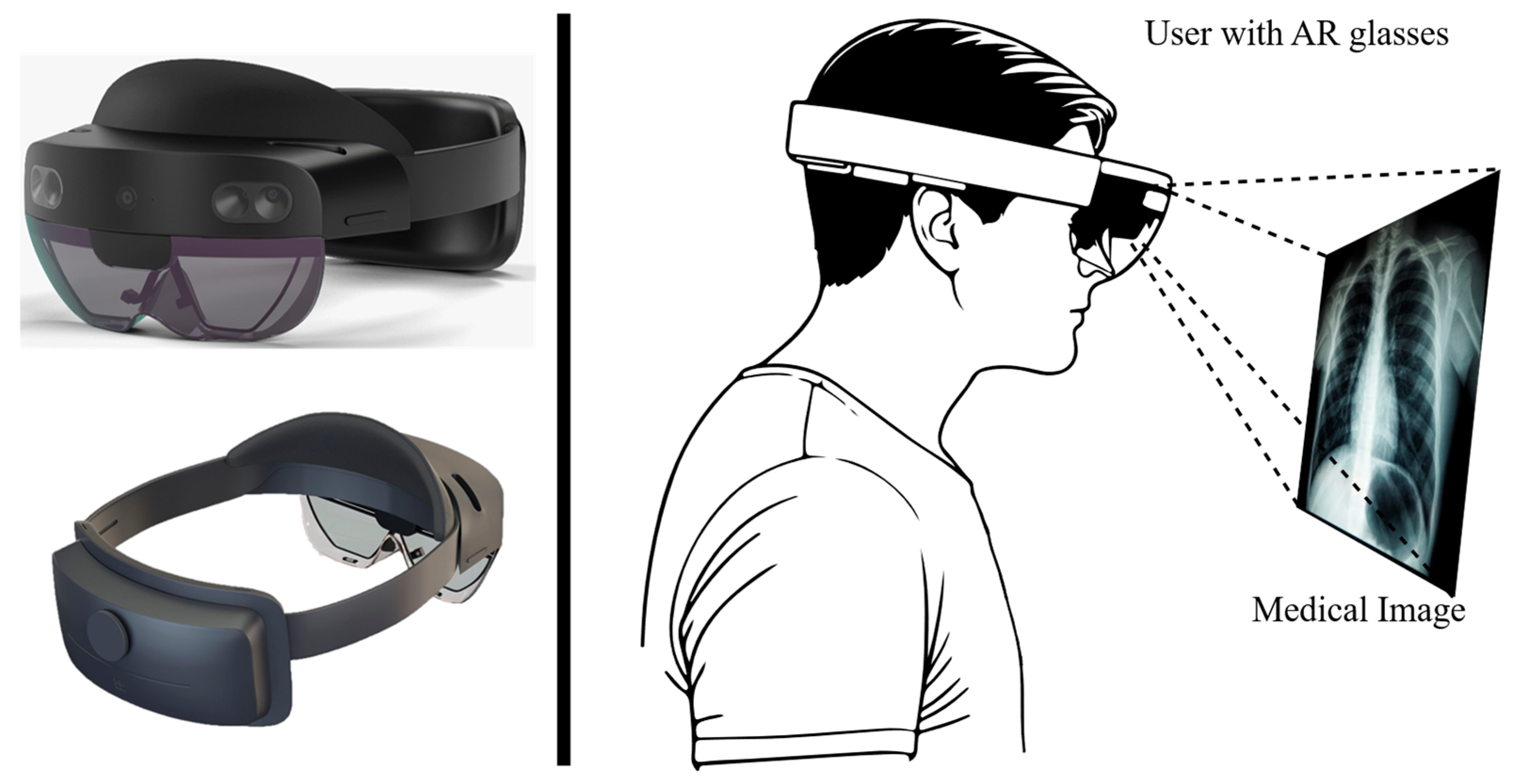
Figure 1. Illustration of HoloLens 2 and its use for the visualization of medical images.
Applsci 15 07648 g001
Figure 2. TG18-OIQ test pattern for evaluating overall image quality with labeling of the image elements contained and the control questions and requirements for the test.
Applsci 15 07648 g002
Figure 3. Test pattern series TG18-LN12 for the investigation of luminance with red marking of the test patterns used to investigate the minimum and maximum luminance.
Applsci 15 07648 g003
Figure 4. Test setup for measuring minimum and maximum luminance and for investigating luminance-to-grayscale conformance.
Applsci 15 07648 g004
Figure 5. Comparison of the luminance measured values of a display device (measured values) with the GSDF [5].
Applsci 15 07648 g005
Figure 6. Comparison of luminance responses of a display device (measured values) and the GSDF [5].
Applsci 15 07648 g006
Figure 7. Experimental setup for measuring color uniformity.
Applsci 15 07648 g007
Figure 8. Comparison of the luminance measurement values of HoloLens 2 with the GSDF.
Applsci 15 07648 g008
Figure 9. Comparison of the contrast response of the HoloLens 2 with the contrast response of the GSDF.
Applsci 15 07648 g009
Table 1. Overview of the materials used to examine HoloLens 2.
CategoryMaterial
Test deviceHoloLens 2
Display softwareVSI HoloMedicine (apoQlar GmbH, Hamburg, Germany)
Test patterns (AAPM):TG18-OIQ
TG18-LN12-03 to TG18-LN12-18
Other test patternsRed (RGB: 255, 0, 0)
Green (RGB: 0, 255, 0)
Blue (RGB: 0, 0, 255)
Measuring devicesLuminance: MAVO SPOT 2 with contact measurement probe (Gossen Foto- und Lichtmesstechnik GmbH, Nürnberg, Germany)
Illuminance: MAVOLUX (Gossen Foto- und Lichtmesstechnik GmbH, Nürnberg, Germany)
Color coordinates: MAVOSPEC BASE (Gossen Foto- und Lichtmesstechnik GmbH, Nürnberg, Germany)
Table 2. Questionnaire for observing participants.
Image ElementControl QuestionsPrimary Display DevicesSecondary Display Devices
1
-
Are the line pairs visible?
YesYes
-
Are the wide, low-contrast line pairs visible?
YesYes
2
-
Are the 5% and 95% patches visible?
YesNo
3
-
Is the “QUALITY CONTROL” text in the white and gray boxes fully legible?
YesYes
-
Is “QUALITY CONTROL” in the black box visible to the penultimate letter?
YesNo
4
-
Are the four low-contrast corners within the two luminance patches visible?
YesNo
5
-
Are the grid lines visible?
YesYes
6
-
Are the 16 luminance patches distinguishable?
16/1616/16
7
-
Are the gradient bars continuous?
YesYes
8
-
Are the black–white and white–black transitions smooth?
YesYes
Table 3. Evaluation of visibility of the image elements in the diagnostic room and office (n = 5). ✓ (green) = Requirement met; ✗ (red) = Not met.
Image ElementControl QuestionDiagnostic Room (2.4 lx)Office (138.7 lx)Rating
P1P2P3P4P5P1P2P3P4P5PrimarySecondary
1
-
Are the line pairs visible?
YesYesYesYesYesYesYesYesYesYes
-
Are the wide, low-contrast line pairs visible?
YesNoNoYesNoYesNoNoYesNo
2
-
Are the 5% and 95% patches visible?
NoNoNoNoNoNoNoNoNoNo-
3
-
Is the “QUALITY CONTROL” text in the white and gray boxes fully legible?
YesYesNoYesNoYesYesYesNoNo
-
Is “QUALITY CONTROL” in the black box visible to the penultimate letter?
NoNoNoNoNoNoNoNoNoNo-
4
-
Are the four low-contrast corners within the two luminance patches visible?
NoNoNoNoNoNoNoNoNoNo-
5
-
Are the grid lines visible?
YesYesYesYesYesYesYesYesYesYes
6
-
Are the 16 luminance patches distinguishable?
15/1615/1615/1614/1614/1615/1615/1614/1613/1614/16
7
-
Are the gradient bars continuous?
NoNoNoNoNoNoNoNoNoNo
8
-
Are the black–white and white–black transitions smooth?
YesYesYesYesYesYesYesYesYesYes
Table 4. Distance between the color coordinates of the five measurement points: top left (TL), top right (TR), center (CE), bottom left (BL), and bottom right (BR) on the HoloLens 2 display. Green = Requirement met; red = Not met.
ColorPositionColor CoordinatesPairingDistance
uvΔuv
RedTL0.44340.5220TL/TR0.016
TR0.45890.5195TL/CE0.037
CE0.48020.5188TL/BL0.064
BL0.50700.5184TL/BR0.033
BR0.47640.5200TR/CE0.021
TR/BL0.048
TR/BR0.018
CE/BL0.027
CE/BR0.004
BL/BR0.031
GreenTL0.10640.5568TL/TR0.011
TR0.11690.5556TL/CE0.031
CE0.13740.5555TL/BL0.025
BL0.13120.5578TL/BR0.065
BR0.17130.5545TR/CE0.021
TR/BL0.014
TR/BR0.054
CE/BL0.007
CE/BR0.034
BL/BR0.040
BlueTL0.17890.1314TL/TR0.005
TR0.18060.1270TL/CE0.017
CE0.17490.1475TL/BL0.032
BL0.17030.1625TL/BR0.022
BR0.17260.1525TR/CE0.021
TR/BL0.037
TR/BR0.027
CE/BL0.016
CE/BR0.006
BL/BR0.010
Disclaimer/Publisher’s Note: The statements, opinions and data contained in all publications are solely those of the individual author(s) and contributor(s) and not of MDPI and/or the editor(s). MDPI and/or the editor(s) disclaim responsibility for any injury to people or property resulting from any ideas, methods, instructions or products referred to in the content.