Review

A Comprehensive Review of Fused Filament Fabrication: Numerical Modeling Approaches and Emerging Trends

1
Mechanical Engineering Department, Instituto Politécnico de Bragança, Campus de Santa Apolónia, 5300-253 Bragança, Portugal
2
Campus Curitiba, Universidade Tecnológica Federal do Paraná, R. Dep. Heitor Alencar Furtado, 5000-Cidade Industrial de Curitiba, Curitiba 81280-340, PR, Brazil
3
Department of Construction and Agronomy, Universidad de Salamanca, 05003 Ávila, Spain
4
Department of Mechanical Engineering, University of Salamanca, Campus Viriato, Avenida Requejo, 49022 Zamora, Spain
5
Centro de Investigação de Montanha (CIMO), Instituto Politécnico de Bragança, Campus de Santa Apolónia, 5300-253 Bragança, Portugal
*
Author to whom correspondence should be addressed.
Appl. Sci. 2025, 15(12), 6696; https://doi.org/10.3390/app15126696 (registering DOI)
Submission received: 28 April 2025 / Revised: 3 June 2025 / Accepted: 11 June 2025 / Published: 14 June 2025

Abstract

:
Fused Filament Fabrication (FFF) has become a widely adopted additive manufacturing technology due to its cost-effectiveness, material versatility, and accessibility. However, optimizing process parameters, predicting material behavior, and ensuring structural reliability remain major challenges. This review analyzes state-of-the-art computational methods used in FFF, which are categorized into four main areas: melt flow dynamics, cooling and solidification, thermal–mechanical behavior, and material property characterization. Notably, the integration of Computational Fluid Dynamics (CFD) and Finite Element Analysis (FEA) has led to improved predictions of key phenomena, such as filament deformation, residual stresses, and temperature gradients. The growing use of fiber-reinforced filaments has further enhanced mechanical performance; however, this also introduces added complexity due to filler orientation effects and interlayer adhesion issues. A critical limitation across existing studies is the lack of standardized experimental validation methods, which hinders model comparability and reproducibility. This review highlights the need for unified testing protocols, more accurate multi-physics simulations, and the integration of AI-based process monitoring to bridge the gap between numerical predictions and real-world performance. Addressing these gaps will be essential to advancing FFF as a precise and scalable manufacturing platform.

1. Introduction

Additive manufacturing (AM), especially material extrusion (MEX), has changed how things are made by allowing the creation of complex geometries, reducing material waste by making parts that are almost the right size, and helping to create components designed for specific uses with special features. Among the various AM technologies, Fused Filament Fabrication (FFF) stands out due to its accessibility, ease of operation, and versatility in material selection [1]. This extrusion-based process involves the controlled deposition of a thermoplastic filament, which is heated to its melting point and deposited layer by layer to construct a three-dimensional object [2]. Its widespread adoption across industries such as aerospace, biomedical, and automotive engineering has led to an increasing demand for improved print quality, mechanical performance, and dimensional accuracy [3,4].
Despite its advantages, FFF presents inherent challenges that impact part quality and reliability. Key factors such as thermal fluctuations, residual stresses, interlayer adhesion, and print parameters influence mechanical strength, dimensional stability, and surface finish [5]. These complicated details require numerical simulations, which provide predictive insights into material behavior, enabling the optimization of deposition strategies [6]. Computational models play a crucial role in analyzing melt flow dynamics, cooling and solidification, stress accumulation, and final material properties [7].
Two predominant simulation methods—Computational Fluid Dynamics (CFD) and Finite Element Analysis (FEA)–are widely employed to model the FFF process [8]. CFD is often used to study how polymers flow and transfer heat, while FEA is used to determine the residual stresses, displacement and strain variation, and how well printed parts perform. The integration of these approaches has facilitated the development of more accurate predictive models, contributing to improved process control and part optimization.
Beyond traditional thermoplastics, recent advancements in fiber-reinforced composites have expanded the capabilities of FFF [9]. The incorporation of short and continuous fibers into polymer matrices has demonstrated significant improvements in mechanical strength, stiffness, and thermal stability, making FFF a viable solution for high-performance applications [4,6,10]. However, fiber integration introduces additional complexities, such as orientation control, dispersion uniformity, and interlayer bonding, requiring advanced numerical modeling techniques to optimize composite performance [7,8].
In parallel, machine learning has emerged as a promising tool for improving FFF process reliability. Early efforts demonstrated real-time defect detection and interlayer quality prediction using AI-based models [11]. Recent studies have expanded these capabilities by integrating simulation-in-the-loop frameworks [12], thermographic imaging supported by machine learning [13,14], and closed-loop control systems for adaptive process adjustment in fiber-reinforced printing [15]. These developments point to the growing role of intelligent, data-driven strategies in enhancing simulation fidelity, and defect mitigation in additive manufacturing.
In addition to summarizing current simulation strategies, this review aims to identify and articulate the main research gaps that limit the predictive capabilities of FFF modeling. These include the lack of standardized validation protocols, the limited integration of multi-scale and multi-physics models, and the scarcity of high-fidelity experimental data for benchmarking numerical predictions. Furthermore, the review highlights the emerging role of machine learning in process monitoring, inverse modeling, and real-time correction, which represents a promising direction for enhancing accuracy and automation in FFF simulations.

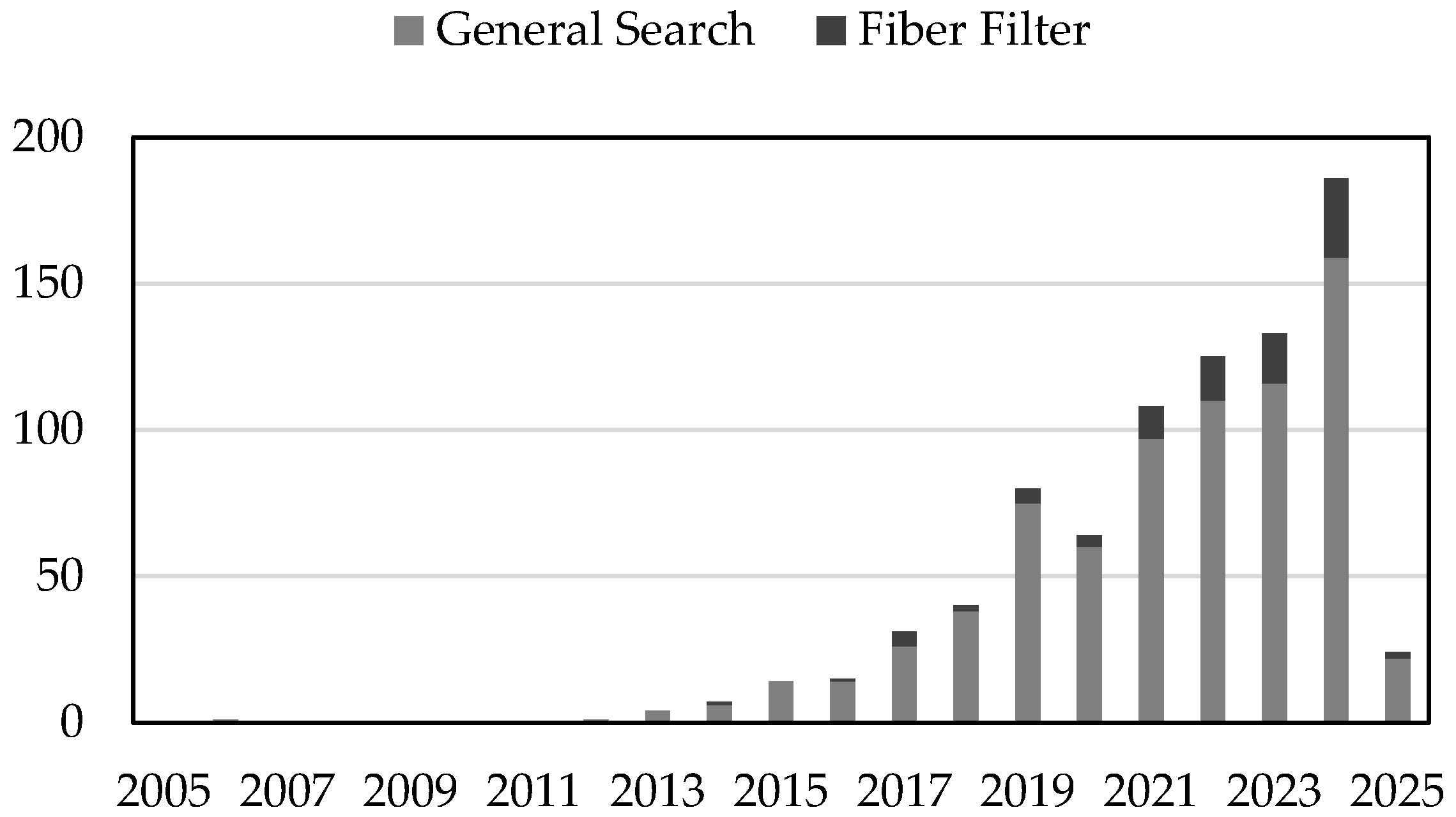
2. Meta-Analysis and Bibliometric Assessment

Bibliometric analysis and meta-analysis are essential tools for understanding the evolution of scientific research, identifying trends, and mapping interconnections between studies. In the context of numerical simulations applied to FFF, these methods provide a structured evaluation of academic progress, technological advancements, and the role of computational modeling in optimizing additive manufacturing processes [16]. As FFF processes become increasingly complex, numerical simulations play a key role in predicting material behavior, improving mechanical performance, and refining process parameters [3].
To evaluate this evolving landscape, a bibliometric analysis was conducted using a structured query applied to indexed databases. The search was designed to capture publications focused on fluid dynamics, structural modeling, and numerical methods within the scope of FFF. The query used was TITLE-ABS-KEY (additive AND manufacturing) AND TITLE-ABS-KEY (numerical AND methods) OR TITLE-ABS-KEY (numerical AND model) OR TITLE-ABS-KEY (simulation) AND TITLE-ABS-KEY (FFF) OR TITLE-ABS-KEY (FFF) AND PUBYEAR > 2004 AND PUBYEAR < 2026. The resulting dataset included 743 publications, which were processed using Scopus, structured with Excel and Power BI, and analyzed through VOS viewer to identify thematic clusters and research trends.
A key focus of recent work has been the integration of fiber-reinforced polymers (FRPs) in FFF. From the initial dataset, ninety studies specifically addressed FRP-related simulations, examining the effects of short and continuous fibers on mechanical performance, deposition quality, and process optimization [5]. This thematic shift has gained momentum particularly since 2019 (see Figure 1), reflecting both technological innovations and a growing interest in advanced composite materials. The bibliometric findings (see Figure 2) show a significant increase in research related to FRPs, indicating that this field is changing quickly and becoming more active within FFF simulation studies.
The reviewed literature was split into four main research areas: melt flow dynamics, which studies how polymers act during extrusion and deposition; cooling and solidification, which looks at heat loss and how it affects layer bonding and leftover stress; thermal–mechanical behavior, which examines stress buildup, warping, and shape changes in printed objects; and material property characterization, which evaluates how different polymer mixes and fiber-reinforced materials affect the final strength of printed parts. To support this analysis, a co-word analysis using VOS viewer showed the importance and connections of the main research topics in the FFF simulation area. The resulting network (see Figure 3) highlights clusters of frequently co-occurring terms, such as material behavior, process parameters, and testing, reflecting the multidisciplinary nature of the field and the growing synergy between computational techniques and experimental investigation.
As the field grows, using detailed simulations, testing them in real life, and monitoring processes in real time will be crucial for making models more accurate and better at predicting outcomes. Future research should focus on creating consistent simulation methods, developing strong experimental testing techniques, and using machine learning to find defects, which will improve the accuracy, dependability, and scalability of FFF-based manufacturing processes. Future research should prioritize the standardization of simulation frameworks, the development of robust validation methodologies, and the incorporation of machine learning–based defect detection systems to enhance the precision, reliability, and scalability of FFF-based manufacturing processes.

3. Fused Filament Fabrication

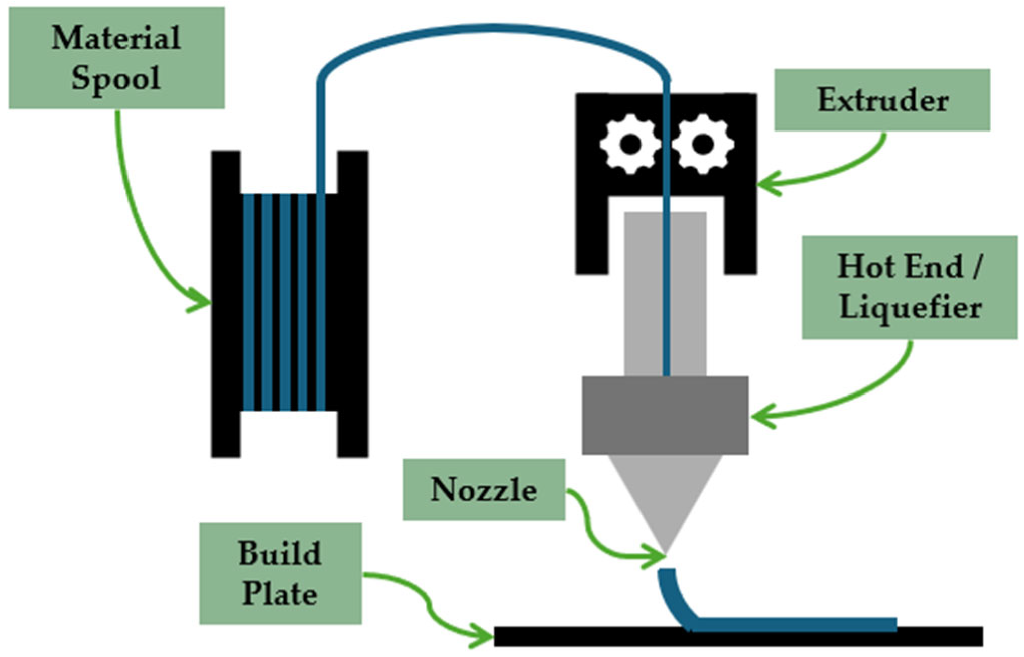
3.1. Overview of the FFF Process

FFF is one of the most widely adopted extrusion-based additive manufacturing techniques, known for its affordability, accessibility, and material flexibility [17]. The process involves feeding a thermoplastic filament through an extruder, where it is heated, melted, and deposited layer by layer onto a build plate. A schematic of this setup is shown in Figure 4. This material deposition follows a digitally defined toolpath to construct three-dimensional parts with varying complexity. A computer-controlled motion system ensures the precise coordination of extrusion and movement, enabling consistent geometric accuracy.
The quality and mechanical performance of printed parts depend on process parameters, including extrusion temperature, layer height, print speed, raster orientation, and infill density. These variables directly influence outcomes such as interlayer bonding, dimensional accuracy, thermal gradients, and final part strength [18]. Commonly used FFF thermoplastics include Polylactic Acid (PLA), Acrylonitrile Butadiene Styrene (ABS), Polyethylene Terephthalate Glycol (PETG), and Nylon, each with distinct thermal and mechanical profiles [19]. In addition to these materials, recent studies have highlighted the growing relevance of semi-crystalline polymers such as polypropylene (PP), especially due to their attractive mechanical and chemical properties. However, their application in FFF presents distinct challenges, including high crystallization-induced shrinkage, reduced adhesion to the build surface, and a strong dependence of final properties on thermal gradients. To address these limitations, current research has proposed strategies such as optimizing the thermal environment, applying surface treatments, and incorporating crystallization kinetics into numerical simulation models [20,21].
To accurately simulate or optimize this process, it is necessary to analyze the FFF workflow in discrete stages. Each phase involves distinct thermal, mechanical, and rheological phenomena that directly influence material behavior and part quality. In addition to polymer-based applications, FFF has also found widespread use in metal casting through the Lost-PLA technique. In this approach, printed PLA parts serve as sacrificial patterns in investment casting, enabling the production of intricate lattice and cellular structures that would be challenging to fabricate using conventional methods. Recent studies have demonstrated the effectiveness of this method for creating complex metallic components in aerospace and structural engineering contexts [22,23]. Owing to its low cost and geometric flexibility, FFF is increasingly employed for prototyping and small-batch production in foundry environments.

3.2. Stages of Material Transformation in FFF

The FFF process encompasses a sequence of tightly coupled thermo-mechanical events, where the polymer undergoes physical, thermal, and rheological transformations that define the quality and performance of the printed part. The accurate modeling of these transformations has become essential to improve dimensional accuracy, optimize process parameters, and reduce manufacturing defects. A modular approach to simulation allows each stage of the process to be analyzed with dedicated tools and methodologies [3].
Figure 5 provides an overview of the main physical stages occurring during FFF. The filament is first melted and extruded through a heated nozzle, where it behaves as a viscous fluid and is deposited layer by layer according to a predefined path. This stage, governed by melt flow dynamics, is followed by cooling and solidification, in which the material transitions from molten to solid and interlayer bonding is established. As the structure grows, thermal gradients result in residual stresses, deformation, and potential warping—phenomena addressed through thermal–mechanical analysis. Finally, the mechanical and structural properties of the printed part are evaluated to determine whether it meets performance requirements, a step that often informs the design of new materials or reinforcement strategies. Each of these stages introduces distinct physical challenges that are targeted through specific numerical modeling strategies.
In the following section, the focus is placed on the rheological properties of thermoplastics, which critically influence extrusion performance, flow stability, and material deposition during FFF.

3.3. Rheological Behavior of Thermoplastics in FFF

Rheology is the study of the deformation and flow properties of materials when subjected to external stress. In the FFF process, understanding the rheological behavior of molten thermoplastics within the heated die is essential for controlling process parameters and determining the quality of the printed part. In FFF, the filament feedstock is initially pulled by pinch rollers into the filament feed tube or directly into the heat break in the hot end. In this configuration, the filament acts as a continuous piston that pushes the molten material through the heated channel and the threaded nozzle onto the build plate [24]. The pressure required to extrude the melt is influenced by both the rheological behavior of the material and the geometric parameters of the print head. A failure in filament feeding can occur when the extrusion pressure exceeds the filament’s ability to support the load, leading to buckling. In this context, the viscosity of the molten polymer determines the resistance to flow, while the compressive elastic modulus of the solid filament determines its ability to carry the compressive load [25].
The primary geometric parameters of the hot end include the inlet diameter (D1), corresponding to the filament size; the outlet diameter (D2) of the nozzle; the convergence angle (β); and the lengths of the extruder nozzle inlet (L1) and outlet (L2) channels [26]. These geometric factors influence the pressure decay along the flow path and therefore the extrusion force required. As illustrated in Figure 6, the molten polymer flows through four regions in the extrusion system. In the initial region (I), flow is pressure-driven within the hot end channel. At the center, both shear stress ( τ ) and shear rate ( γ ˙ ) are minimal, while the axial velocity is maximal (vz). At the tube walls, the situation reverses—shear stress and shear rate reach their maximum values, while the velocity drops to zero [27]. This condition creates a shear gradient across the cross-section, where molecular orientation varies with the degree of shear. Molecules near the wall become increasingly aligned, while those at the center remain more disordered [28].
The mechanical behavior of this flow can be described by basic rheological equations that relate to stress and deformation under flow conditions. Shear stress (τ) is defined as the force applied (F) divided by the cross-sectional area (A) of the channel, expressed as: τ = F / A. Shear rate ( γ ˙ ), on the other hand, is defined as the velocity gradient across the radius of the flow channel, where dvz is the variation of axial velocity across the tube diameter and dy is the distance from the center of the tube, yielding: γ ˙ = dvz/dy.
The polymer melt rheological behavior depends on the applied shear rate. At exceptionally low shear rates, typically below 101 s−1, thermoplastics is considered a Newtonian fluid, exhibiting constant viscosity. In most polymer processing conditions, including FFF, shear rates fall between 101 and 105 s−1, where the fluid exhibits non-Newtonian, shear-thinning (pseudoplastic) behaviors. At even higher shear rates, viscosity may plateau again, restoring Newtonian behavior [28]. Figure 7 illustrates this relationship on a logarithmic scale. For FFF, shear rates within the nozzle are typically in the range of 100–200 s−1 [25]. Specifically for PLA, pseudoplastic behavior has been observed between 1 and 103 s−1 [29].
This non-Newtonian behavior is described by the Power Law (Ostwald–de Waele) model, where k is the consistency index and n is the flow behavior index: τ = k. γ ˙ n. Mathematical models for simulating flow in FFF have used this equation [26]. A value of n = 1 indicates Newtonian behavior, while n < 1 characterizes pseudoplastic fluids [30]. The lower the value of n, the more pseudoplastic the material, resulting in a flatter flow front. The velocity profile shown in Figure 7 corresponds to a Newtonian fluid [31]. After region I, the molten polymer enters the convergent channel (region II), where the flow becomes elongational due to the change in cross-section. This behavior is analogous to the inlet region of a traditional extrusion die. In region III, the flow again becomes pressure-driven, but at increased velocity due to the smaller diameter. Upon exiting the nozzle (region IV), the flow profile does not present speed variation along the extrudate diameter, as the polymer enters at ambient pressure and undergoes relaxation, leading to an increase in diameter—a viscoelastic phenomenon known as extrudate swell (D3/D2 ratio) [27]. It is considered that the molten polymer undergoes an axisymmetric contraction flowing through the nozzle [32]. The cylindrical volume in the region of the inlet nozzle is elongated and its diameter is reduced; after it passes the convergent channel, it increases again at the nozzle outlet, reducing its length [27].
Molten polymers show a dependence on the speed, intensity, and time at which stress is applied, i.e., it is dependent on their thermo-mechanical history. They can partially return to their original shape after being stretched because their long molecular chains line up when stressed and then relax back to a random state when the stress is gone [31]. This behavior generates normal stress components when the polymer is out of the nozzle, which causes swell [28]. Whether in fluid or solid state, this behavior is called viscoelastic [33], as mathematical theories are applied in both cases [34]. The extent of extrudate swell depends on the thermo-mechanical history of the melt. The longer the residence time inside the nozzle, the greater the relaxation of elongational deformation and the smaller the residual contribution to swell. However, shear-induced elastic deformation within the nozzle still contributes to swelling. To mitigate this effect, it is recommended to reduce the extrusion speed, increase the processing temperature (at constant shear rate), increase the length-to-diameter ratio (L2/D2), and reduce the diameter ratio (D1/D2) [28,34]. Other elastic effects during flow include melt fracture, shark skin, and draw resonance. These phenomena are caused by flow instabilities arising from elastic turbulence at the nozzle inlet, especially at high deformation rates in elongational flow, where stress levels exceed the cohesive strength of the polymer [31,35].
Since viscosity is temperature-dependent, extrusion behavior is strongly influenced by thermal conditions. Excessively elevated temperatures can lead to discharge fluctuation and thermal degradation, while low temperatures increase viscosity and pressure demand, potentially resulting in melt fracture [31]. The average level of molecular orientation and residual stress in the printed part depends on three main factors: I) the shear-induced orientation during deposition; II) the relaxation time of the polymer chains (typically between 0.1 and 0.5 s for certain polymers); and III) the effective cooling time between processing temperature (Tp) and solidification temperature (Ts). This cooling time is determined by the size and geometry of the part, the polymer’s specific heat, and the temperature intervals Tp–Ts and Tp–Tr, where Tr is room temperature [34]. The filament softens and melts in the heater block, which contains a machined flow channel. The melt quantity depends on the heat flux and material feed rate [24,26]. The rate of thermal exchange is governed by the material’s thermal diffusivity, which is determined by its conductivity, density, and specific heat [30]. As the temperature increases, viscosity decreases, reducing pressure drop and enhancing bonding between layers [26]. The pressure inside the die is controlled by variables: the geometry of the flow channel, the rheological properties of the melt, the temperature distribution, and the volumetric flow rate [35]. Material deposition is based on a constant volumetric displacement principle, where the flow rate is governed by the speed of the counter-rotating roller [24].

4. Numerical Simulation Applied to the FFF Process

Based on the stages illustrated in Figure 5, simulations are grouped into four categories: melt flow, cooling and solidification, thermal–mechanical behavior, and material property characterization [3]. Melt flow simulations focus on shear forces, viscosity variations, and flow stability, ensuring precise material deposition and interlayer bonding [36]. Cooling and solidification studies explore thermal gradients, heat dissipation mechanisms, and their effects on mechanical properties, which are key to preventing warping and structural defects [37]. Thermal–mechanical models predict stress distribution, distortion patterns, and deformation risks, aiding in process optimization and defect mitigation [1,38]. Finally, material characterization simulations allow for the correlation between process parameters and final material properties, ensuring that predictions align with experimental validation [3].
The following sections provide an in-depth review of each numerical modeling domain, detailing key methodologies and significant findings that contribute to advancing FFF-based additive manufacturing.

4.1. Melt Flow

The melt flow behavior in FFF significantly influences the extrusion stability, the deposition accuracy, and the interlayer adhesion, which directly affect the mechanical properties and dimensional precision. Understanding polymer melt dynamics within the hot end, during extrusion, and after deposition enables control over print quality and the optimization of process parameters. CFD has advanced predictions of melt flow, specifically addressing viscosity effects, shear-induced deformation, and heat transfer processes.
Temperature and shear rate, closely related to extrusion speed, primarily govern the melt flow of thermoplastic materials during deposition. Due to the low pressures in FFF, these rheological factors dominate flow dynamics. Comminal et al. (2018) [39] developed a CFD model that considered polymer flow as an isothermal Newtonian fluid, demonstrating how filament geometry depends on nozzle-to-substrate gap and extruder-to-substrate velocity ratio. Their findings emphasize the precise control of deposition parameters to achieve optimal filament shape and interlayer adhesion. Figure 8 shows how the strand shape (W/H) and density (A/(W·H)) change based on the distance from the nozzle to the surface (g/D) and the speed of the material flow (V/U). As g/D increases, the aspect ratio decreases, indicating a wider and flatter strand profile, while the compactness is maximized at intermediate V/U values, reflecting the interplay between shear rate and material deposition behavior.
Building on their earlier findings, Serdeczny et al. (2022) [40] developed an advanced CFD model, incorporating viscoelastic rheology to simulate the non-isothermal polymer flow more accurately through the hot end in filament-based additive manufacturing. Unlike previous models that assumed fully liquefied flow or employed generalized Newtonian approximations, this approach accounted for shear and elongational stresses, offering improved predictive accuracy for filament feeding forces across varying process conditions. The model was experimentally validated and demonstrated strong alignment with measured data, particularly under high flow rates. Furthermore, it enabled the parametric optimization of key hot-end geometries, such as liquefier length, capillary diameter, and inlet angle, highlighting their impact on flow stability and extrusion performance. These findings reinforce the earlier conclusions by Serdeczny et al. (2020) [41], who identified recirculation regions at the solid–melt interface as critical factors that influence temperature distribution and pressure buildup within the nozzle, underscoring the importance of physically representative rheological modeling (Figure 9).
Nozzle design plays a fundamental role in controlling melt flow dynamics in extrusion-based additive manufacturing. Jeong et al. (2021) developed a nozzle modification strategy aimed at controlling the orientation of filler particles during extrusion [42]. By embedding an orifice geometry into the nozzle, they induced the perpendicular alignment of anisotropic reinforcements, which directly influenced the mechanical anisotropy of printed parts. Through combined experimental and numerical analysis, the study demonstrated how nozzle-induced flow fields affect particle orientation, highlighting the importance of microstructural control in melt flow modeling and the functional optimization of fiber-reinforced filaments [42].
Building on this notion of nozzle-function tailoring, Schuller et al. (2024) [43] employed CFD simulations coupled with global optimization algorithms to improve nozzle geometry for high-speed FFF applications. By parameterizing the nozzle profile using spline curves and enforcing manufacturability constraints, they identified geometries that significantly reduce pressure drops while maintaining effective flow characteristics. Experimental validation confirmed these findings, demonstrating that optimized nozzles—particularly the organic and PET-G-specific designs—lowered pressure drop by up to 67%, with reduced backflow and improved extrusion force control. These results emphasize that tailoring nozzle design to polymer rheology can directly enhance printing performance, precision, and throughput, employing nozzle optimization as a valuable tool in the advancement of FFF processes (see Figure 10).
At high extrusion speeds, melt flow presents additional complexities. Phan et al. (2020) [29], through CFD simulations in ANSYS Fluent (Version Ansys 2020 R1), observed that rapid extrusion reduced the heating period, resulting in incomplete polymer melting, filament distortion, and decreased accuracy. They indicated that current numerical models fall short under high-speed conditions and recommended developing advanced thermal and rheological models to improve predictive accuracy. This limitation is closely tied to the viscoelastic nature of polymer flow at elevated deformation rates, particularly during elongational deformation in the nozzle. Figure 11 presents the pressure drop of PLA melt as a function of shear rate, measured using both capillary and orifice dies. The steep increase in pressure drop with shear rate underscores the dominance of elongational effects in high-speed extrusion and supports the adoption of the Phan–Thien–Tanner (PTT) model to predict flow resistance more accurately under these conditions. These experimental insights validate the simulation observations and highlight the need for rheological models that capture pseudoplastic behavior when aiming to scale FFF processes to higher speeds.
Collectively, these studies indicate that melt flow behavior in FFF strongly depends on extrusion conditions, including nozzle temperature, feed rate, and layer height. CFD-based approaches effectively characterize flow instabilities, optimize deposition, and enhance interlayer bonding. Nevertheless, melt flow alone does not solely determine the mechanical properties of printed components. Post-deposition cooling and solidification introduce thermal dissipation and phase transitions that significantly impact residual stresses and structural stability. The subsequent section explores these thermal mechanisms and their role in interlayer adhesion, mechanical strength, and dimensional accuracy in FFF.

4.2. Cooling and Solidification

The cooling and solidification phase in FFF is designed to achieve optimized interlayer adhesion, mechanical performance, and dimensional accuracy (Liparoti et al., 2021) [44]. Removing heat properly during the polymer deposition process helps to create strong bonds between layers by allowing effective molecular diffusion. Therefore, it is necessary to control the heat transfer mechanisms (conduction, convection, and radiation) to maintain structural integrity and ensure high-quality printed components. Among these mechanisms, conduction has been identified as the dominant heat transfer mode. Costa et al. (2014) [45] confirmed that conduction between deposited filaments and the build plate significantly outweighs convection and radiation in cooling efficiency. They recommended strategies such as preheating the build surface or controlling chamber temperatures to effectively reduce thermal gradients, thereby minimizing warping and delamination.
Heat transfer also determines the quality of filament bonding. Zhang et al. (2017) [46] developed a 3D transient thermal model and found that reheating from newly deposited layers improved molecular entanglement, whereas rapid cooling negatively impacted interlayer strength. In addition to the thermal findings, their study employed the Element Birth and Death technique in ANSYS to simulate the sequential nature of layer deposition. This approach allowed the model to dynamically activate elements as new material was added, accurately capturing the temporal evolution of the thermal field and heat accumulation across layers. As a result, the simulation provided enhanced insight into local reheating effects, cooling gradients, and the influence of deposition timing on interlayer temperature history. Similarly, Zhou et al. (2016) [47] used FEA, which considers how materials behave at different temperatures, and found that quick cooling is harmful because it limits how materials can mix, weakens their stickiness, and raises internal pressures. To optimize bonding quality, they recommended controlling cooling rates through adjustments in build plate temperature and using enclosed printing environments.
Further deepening the understanding of adhesion, Coogan and Kazmer (2017) [48] developed a diffusion-based healing model, emphasizing maintaining interfacial temperatures above the polymer’s glass transition temperature (Tg) to enhance polymer chain diffusion effectively. Similarly, Lepoivre et al. (2020) [49] utilized infrared thermography and thermal simulations to explore heat transfer and adhesion during FFF. They demonstrated that filament adhesion depends heavily on coalescence and polymer chain reptation, the thermal motion of polymer chains that allows them to entangle and effectively bond. Both phenomena are driven by the thermal history experienced during the process. Their findings indicate that precise thermal management, particularly accurate control over the cooling rate, significantly enhances mechanical performance, especially in high-performance thermoplastics such as PEKK (see Figure 12).
Addressing practical constraints, Go et al. (2017) [50] identified key limitations such as extrusion force, heat transfer efficiency, and printhead motion in FFF. Their results indicated that elevated nozzle temperatures enhance extrusion speeds but are limited by insufficient thermal conduction within the filament core, increasing extrusion forces and the risk of filament buckling. To address this, they suggested longer liquefiers to enhance heating efficiency, enabling higher flow rates without excessive force. These thermal limitations are further illustrated in Figure 13, where finite element simulations show that, as flow rate increases, heat penetration into the filament core decreases significantly, especially near the liquefier inlet. At higher build rates, core temperatures drop, highlighting the reduced thermal residence time. These findings support the recommendation to implement extended heating zones and underscore the critical role of balanced thermal management in ensuring efficient material flow and preventing mechanical instabilities during the printing process.
Enhancing print reliability, Jin et al. (2020) [11] developed an AI-based real-time monitoring system using computer vision and embedded strain sensors to promptly detect interlayer defects such as warping and delamination. Their system successfully identified defects early, significantly improving reliability and reducing material waste. The relationship between cooling dynamics and residual stress generation further clarifies the role of thermal management in FFF. Xia et al. (2018) [51] employed CFD simulations to reveal that uneven cooling leads to differential thermal contraction, causing localized stresses and dimensional inaccuracies. By incorporating temperature-dependent shrinkage models, their simulations improved predictions of residual stresses. Extending these findings, Serdeczny (2020) [52] developed a comprehensive numerical model, indicating that the rapid cooling near the nozzle exit increases residual stresses, resulting in geometric distortions. Experimental validation confirmed that higher extrusion temperatures enhance adhesion but simultaneously increase the residual stress of thermal origin.
Together, these studies underscore the role of temperature evolution in determining bonding quality and dimensional outcomes during FFF. However, the development of internal stresses resulting from non-uniform cooling and constrained thermal contraction cannot be fully explained by thermal considerations alone. To address this, the following section focuses on how residual stress accumulation and thermally induced deformation evolve during the printing process, and how they influence the structural integrity and reliability of FFF-manufactured parts.

4.3. Thermal–Mechanical

Thermal–mechanical behavior in FFF involves the interaction between thermal gradients, material shrinkage, and mechanical constraints imposed by the layered manufacturing process. These interactions lead to the development of residual stresses and strain localization, which can result in defects such as warping, delamination, or dimensional instability. Numerical approaches typically address these effects by coupling transient thermal simulations with mechanical models that incorporate temperature-dependent material properties and layer-by-layer deposition sequences.
One of the earliest mathematical models for warp deformation in FFF was developed by Wang et al. (2007) [53], who analyzed thermal stresses induced by material contraction during cooling. Their study examined the influence of deposition layer count, section length, chamber temperature, and material shrinkage rate on deformation. They found that higher chamber temperatures reduce warp deformation, while larger stacking sections and higher shrinkage rates increase it. Their model provided valuable insights into process optimization, emphasizing that adjusting raster angles and partitioning deposition areas can significantly improve dimensional accuracy. However, the model does not fully account for residual stress evolution during cooling or the effects of complex geometries, limiting its applicability for intricate parts.
To expand simulation capabilities and reduce computational demands, Bhandari and Lopez-Anido (2020) [54] introduced a discrete-event thermal model capable of capturing transient heat transfer behavior during the printing process. Their approach demonstrated good agreement with more computationally intensive methods, making it suitable for efficient thermal prediction across various geometries and parameter settings. More recently, Jiang (2023) [55] developed a high-fidelity thermal simulation framework specifically aimed at improving the prediction of temperature fields and guiding the process optimization of printed polymer and composite parts. The study emphasized the importance of accurately capturing spatiotemporal temperature gradients to mitigate stress concentrations and improve structural performance.
Building on earlier findings, advanced finite element approaches have been developed to simulate stress accumulation and deformation in FFF. Morvayová et al. (2023) [56] developed a 3D thermo-mechanical finite element model to predict dimensional accuracy, defect formation, and residual stresses in wood/PLA biocomposites fabricated via FFF. Their study identified uneven filler distribution and high hydrophilicity as major challenges, influencing printability and final part stability. The model, validated experimentally, demonstrated that residual stresses are sensitive to layer thickness and extrusion temperature. As shown in Figure 14, residual stress increased significantly with thicker layers, with values peaking at 48 MPa for 0.25 mm layer thickness. Lower nozzle temperatures and thinner layers resulted in reduced thermal gradients and lower residual stress values, especially in the lower portions of the parts, which remained more constrained by platform adhesion. These findings reinforce the need to optimize process parameters, especially for heterogeneous biocomposites, and highlight current limitations in capturing anisotropic thermal–mechanical interactions in such materials.
Another finite element modeling approach was developed by Cattenone et al. (2018) [57], who used ABAQUS to predict distortions in FFF with a sequential element activation method. Their study showed that smaller time steps improve temperature accuracy but have minimal effect on residual stress, while finer meshing improves stress gradient predictions but significantly increases computational cost. Their model was validated against experimental data for a planar spring and a bridge model, showing good agreement, with vertical displacement errors of 23% and 12%, respectively. However, the study highlighted the need for better adhesion models to capture first-layer interactions and improved methods for predicting part detachment and warping behavior.
The impact of temperature variations on residual stress and part deformation was also investigated by El Moumen et al. (2019) [58], who developed a 3D thermo-mechanical model to predict temperature gradients, residual stresses, and delamination in FFF-printed polymer composites. Their results showed that rapid temperature changes between layers increase stress concentrations, raising the risk of delamination. Their analysis also found that filament deposition produces higher temperature gradients than layer-by-layer printing, leading to more distortion and stress accumulation. Experimental validation showed temperature deviations below 5%, confirming the model’s accuracy. However, they emphasized the need for better modeling of anisotropic mechanical behavior and complex thermal interactions to improve stress predictions.
These studies jointly confirm that residual stresses and thermal deformations remain significant challenges in FFF, requiring a combination of multi-scale modeling and optimized print parameters to mitigate these limitations. The next section will explore the role of material properties and their characterization, detailing how processing conditions, fiber integration, and post-processing techniques influence final part performance.

4.4. Material Property Characterization

The mechanical and thermal behavior of materials in FFF depends on process parameters, material composition, and reinforcement strategies [36]. Factors such as layer thickness, infill density, raster orientation, and cooling rate influence strength, ductility, and failure mechanisms in printed parts [10]. To optimize material performance and structural integrity, researchers have combined experimental testing, numerical modeling, and real-time defect detection to evaluate how printing parameters affect mechanical behavior.
The influence of printing parameters on mechanical properties has been studied. Croccolo et al. (2013) [59] and Domingo-Espin et al. (2015) [60] investigated the mechanical behavior of parts produced via FFF, focusing on ABS-M30 and Polycarbonate (PC), respectively. Both studies concluded that strength and stiffness were highest when filament layers were aligned with the loading direction, whereas perpendicular loading resulted in weaker performance due to reduced interlayer bonding. Analytical and finite element models developed by these authors closely matched experimental results, achieving average deviations below 10%. However, both studies emphasized the need for improved modeling to better capture plastic deformation and failure behavior beyond the elastic limit. The experimental and numerical configurations used by Domingo-Espin et al. are illustrated in Figure 15.
In addition to mechanical performance, geometric accuracy and surface quality are crucial for material characterization. García Plaza et al. (2019) [61] studied how build orientation, layer thickness, and feed rate affect PLA part dimensions, flatness, and surface texture. Thinner layers improved dimensional accuracy, while feed rate had minimal impact. Flatness errors primarily resulted from variations in layer thickness and extruder acceleration/deceleration, with higher feed rates increasing material accumulation. Surface roughness increased with thicker layers due to the stair-stepping effect inherent in layered manufacturing. The study highlighted the importance of precise extruder control and optimized parameters for better surface quality and geometric accuracy.
A simplified numerical model was proposed by Zouaoui et al. (2021) [62] to predict the mechanical behavior of FFF 3D printing parts that are built from an ABS pre-structured material. The model effectively addresses the anisotropic build configuration by assigning local material reference frames to individual mesh elements. It treats the material as homogeneous and employs specific material constants to introduce anisotropy associated with intricate deposition trajectories. Their results verify that the material exhibits quasi-isotropic elastic behavior, as the longitudinal and transversal Young’s modulus are approximately equivalent. The strength anisotropy in tensile specimens with varying raster angles has been determined by combining Hill’s criterion with the filament’s plastic flow curve. The longitudinal direction possesses the highest yield strength and a ductile behavior, whereas the transversal direction is the weakest and demonstrates fragile behavior at the yielding point. These effects are quantitatively illustrated in the comparison between simulated and experimental load–displacement curves shown in Figure 16.
Advancing such models requires precise experimental characterization to obtain reliable and process-relevant material data. Dynamic Mechanical Analysis (DMA) provides viscoelastic properties, such as storage and loss moduli across a range of temperatures, that are commonly used to model stress relaxation and residual stress evolution [63]. Differential Scanning Calorimetry (DSC) is widely applied to identify thermal transitions, including glass transition temperature (Tg), melting point (Tm), and crystallinity, which affect shrinkage and stiffness, particularly in semicrystalline polymers like PLA and PA. Additionally, micro-computed tomography (micro-CT) allows the non-destructive, high-resolution imaging of internal porosity, fiber distribution, and interlayer adhesion. These structural insights support the validation of mesoscale simulations and help to relate internal features to mechanical behavior [64].
Material failure mechanisms have also been studied extensively. Garg and Bhattacharya (2017) [65] conducted FEA and experimental tests to study the effect of raster angle and layer thickness on tensile failure. They found that thinner layers improve elongation and load-bearing capacity due to the higher number of load-aligned layers, while thicker layers result in higher tensile strength because of fewer air voids and stronger interlayer bonds. Figure 17 illustrates the stress distribution across samples with different raster angles and layer thicknesses. Specimens with 0° rasters exhibit more uniform stress distribution along the loading direction, while those with 90° rasters show stress localized at the interlayer regions, leading to early delamination. In 0°/90° raster configurations, failure typically initiates in the 90° layers and propagates through the structure, ending in brittle fracture of the 0° layers. These results highlight the need for refined models that can better capture interlayer bonding behavior and failure progression in anisotropic printed parts.
Expanding on anisotropy in AM, Dai et al. (2025) [66] reviewed the mechanical behavior of additively manufactured materials, focusing on how the layer-by-layer process creates structural heterogeneity, residual stress, and defects. Their analysis found that materials, process parameters, and post-processing techniques all influence anisotropic behavior, with metals, polymers, and composites responding differently. Crystal plasticity models accurately predict anisotropy in metals, but polymer models often oversimplify microstructural effects. They emphasized the need for improved modeling approaches that integrate machine learning and multi-scale physics but noted that many current models lack validation across different AM processes, highlighting the need for better experimental benchmarking and real-time simulation improvements.
To improve failure detection, Fu et al. (2025) [12] developed a simulation-in-the-loop framework for real-time structural validation in AM. Their system combines FEA with in situ defect detection, using a U-net image segmentation model to analyze defects layer by layer. Experimental tests on a material extrusion printer demonstrated that the framework could predict failure strength within 5% accuracy, allowing for early defect detection and automated print termination when necessary. They found that defect size and distribution directly influence stress accumulation, but computational efficiency remains a challenge in complex geometries and high-speed printing. The progression of strain distribution in a defective sample under tensile loading is illustrated in Figure 18.
To further enhance failure prediction and quality assurance in FFF, thermography-based approaches have also been explored. Rodríguez-Martín et al. (2020) [13] demonstrated the use of active thermography supported by machine learning to predict internal defects in polymer-based additively manufactured components. Their methodology enabled the non-destructive, real-time identification of internal flaws from thermal sequences, improving process monitoring and reliability. Building on this, Rodríguez-Martín et al. (2022) [14] employed step-heating thermography in combination with simulation and ML models to accurately estimate internal defect sizes. Their results underscore the potential of integrating thermal diagnostics with data-driven techniques to support in situ structural validation and quantitative defect characterization. These contributions reinforce the growing relevance of hybrid experimental–computational methods in advancing defect-aware modeling for FFF.
However, despite their potential, current validation strategies still face critical gaps. Traditional methods, such as mechanical testing under simplified geometries [59,60] or dimensional accuracy analysis [61], often neglect microstructural irregularities and transient thermal effects. Techniques like micro-computed tomography (µCT) [64], simulation-in-the-loop validation [12], and thermography supported by machine learning [13,14] have improved the ability to detect and quantify internal defects, but their adoption remains limited due to equipment costs, a lack of standardized protocols, and challenges in integrating experimental data into numerical frameworks. Therefore, advancing reliable FFF simulation will require the broader implementation of high-fidelity, non-destructive validation tools and coordinated efforts to establish shared benchmarks across materials, geometries, and simulation platforms.
Building on this foundation, future research should prioritize advanced modeling techniques capable of capturing anisotropy, residual stresses, and defect formation more effectively. Integrating machine learning with multi-scale physics-based simulations and real-time process monitoring could significantly enhance predictive accuracy and efficiency. In the next section, the influence of fiber reinforcement on material performance is examined, specifically addressing how fiber type, orientation, and distribution impact composite properties.

5. Fiber-Reinforced Composites

Most polymers employed in Fused Filament Fabrication (FFF) exhibit inherently low mechanical properties; one effective strategy to enhance their performance is reinforcement with fibers. Integrating fiber reinforcements into thermoplastic matrices significantly improves mechanical strength, dimensional stability, and thermal performance in FFF [67,68]. Short fiber-reinforced composites (SFRCs), commonly carbon, glass, or natural fibers, improve stiffness and moderately increase strength, but their properties remain anisotropic due to random fiber orientations. Continuous fiber-reinforced composites (CFRCs) provide superior mechanical properties comparable to polymeric materials but require precise fiber alignment and controlled deposition, complicating the printing process.
Yang et al. (2017) [69] developed a coupled Smoothed Particle Hydrodynamics (SPH) and Discrete Element Method (DEM) model to simulate the 3D printing process of fiber-reinforced polymers. Their study explored the behavior of both short glass fibers in ABS and continuous carbon fibers in Nylon during extrusion. As shown in Figure 19, short fibers tend to align with resin flow, but interactions near the nozzle walls can introduce chaotic movement and reduce alignment. In contrast, continuous fibers remain centered early in the extrusion but undergo significant bending deformation and stress buildup as printing progresses. This deformation, along with fiber–nozzle contact, can lead to tool wear and performance reduction. The model also demonstrated how nozzle geometry and extrusion velocity influence flow fields and fiber positioning. Although the model lacked thermal and shrinkage considerations, it provided valuable insights into fiber–resin interactions and established a foundation for multi-physics simulations.
Yang et al. (2022) [70] further studied fiber breakage and orientation experimentally using X-ray micro-computed tomography (μCT), finding that smaller nozzles increased fiber breakage and larger layer heights improved alignment but increased porosity, thus decreasing tensile strength. Their results highlighted critical trade-offs between fiber integrity and mechanical performance.
Topology optimization has emerged as an effective approach for improving composite performance. Yang et al. (2022) [71] developed a topology optimization method aligning fiber paths with stress distributions, improving stiffness-to-weight ratios and manufacturability. Experimental validations confirmed improvements but emphasized the need for better fiber continuity and optimized path planning. Yap et al. (2024) [72] similarly demonstrated that topology optimization improved stress distribution and structural performance compared to shape optimization, although defects and fiber misalignments from manufacturing processes indicated that models should better reflect practical constraints. These observations are further supported by Figure 20, which presents numerical stress analysis, crack initiation zones, and μCT scans of failed specimens.
Broader reviews by Brenken et al. (2018) [68] emphasized that fiber alignment increases stiffness but reduces transverse strength, highlighting interlayer adhesion as critical. Large-scale systems, such as Big Area Additive Manufacturing (BAAM) and Large-Scale Additive Manufacturing (LSAM), improved production speeds but still face challenges in accurately predicting fiber orientation, improving interlayer bonding, and modeling residual stress. Brenken et al. (2019) [73] validated finite element models predicting residual stresses and deformation in printed composites but identified limitations in modeling layer adhesion failures, especially for large-scale parts. Tekinalp et al. (2014) [67] experimentally demonstrated high fiber alignment in carbon fiber-reinforced ABS composites, significantly enhancing mechanical performance despite increased porosity. These composites matched or exceeded aluminum alloys’ specific strength, demonstrating their structural potential.
Despite these advancements, real-world applications still face major challenges such as void formation, fiber misalignment, and weak interfacial bonding. Zhang et al. (2025) [74] and Plamadiala et al. (2025) [75] reviewed common defect types and process-level strategies to mitigate them, including in situ heating and tailored deposition. However, these techniques offer only partial solutions and often require compensatory adjustments to extrusion temperature, nozzle geometry, or material formulation.
These limitations have prompted efforts to more accurately incorporate experimental imperfections into simulation models. For example, Somireddy et al. (2022) [76] developed and compared two finite element models of ABS–short carbon fiber composites, aiming to capture the effects of interfacial defects and fiber alignment. As shown in Figure 21, Model CM-1, based on virgin ABS properties, significantly overestimated stiffness and strength, while CM-2, which incorporated tensile data from printed specimens, more accurately reflected the nonlinear behavior observed in experiments. This comparison underscores the importance of using real defect-informed material data to improve the predictive reliability of composite FFF simulations.
Building upon the need to better capture and control defect formation, recent studies have explored intelligent control strategies during the printing process. Lu et al. (2023) [15] developed a deep learning-assisted framework for real-time defect detection and closed-loop adjustment in the fabrication of continuous fiber-reinforced polymer composites. By integrating sensor data with neural network-based decision models, their system detected anomalies and adaptively modified print parameters to prevent defect propagation. This architecture not only improved process reliability but also demonstrated the feasibility of combining artificial intelligence with physical simulation to enhance control in fiber-reinforced FFF.
Taken together, these studies reveal both the potential and the persistent limitations of fiber-reinforced FFF. While predictive models have become increasingly sophisticated, they still struggle to fully capture the coupled effects of fiber orientation, bonding quality, and defect distribution. One of the key remaining gaps is the ability to link microstructural behavior to macroscopic performance. Recent approaches—such as thermal–mechanical models with in situ deformation tracking [77] and hybrid machine learning frameworks that incorporate physical laws [78]—have begun to address this. However, progress is constrained by the lack of standardized validation methods. Moving forward, a combination of high-fidelity simulations, robust experimental datasets, and process-aware material models will be essential to bridge the gap between theory and application in composite FFF.

6. Systematic Literature Review

6.1. General Trends in Simulation Approaches

To provide a comprehensive overview of the current modeling approaches in FFF using PLA, a comparative analysis of relevant studies was conducted. Table 1 summarizes the characteristics of the selected studies, including materials analyzed, methodologies employed, simulation software used, key parameters, and principal findings. This synthesis offers a structured basis for understanding the modeling strategies applied in the context of FFF with PLA. A consistent feature across the studies is the reliance on numerical tools adapted to simulate thermal, mechanical, and rheological behavior during filament deposition. These include commercial platforms equipped with proprietary or customizable algorithms, such as Ansys®, Abaqus®, COMSOL [79], UMFPACK [80], Slic3r [58], multi-scale algorithms [81], and other in-house numerical models [82].
The application of these tools reflects a focus on replicating the physical mechanisms of material flow, interlayer bonding, and process-induced stress, often with extensions to capture process-specific behavior through subroutines or custom modules. Within this context, Ansys® and Abaqus® appear as the most prominently applied platforms in the FEA-based simulation of PLA in FFF. The next subsection presents a comparative evaluation of their roles, capabilities, and limitations, based on the selected literature.

6.2. Comparative Evaluation of Abaqus and Ansys

Abaqus® has been widely used to simulate the mechanical behavior of FFF-processed PLA, particularly through implementations that support advanced thermo-mechanical modeling. Favaloro et al. (2017) [83] explored recent functionalities in Abaqus®, based on the sequentially coupled thermo-mechanical approach developed by Brenken (2017) [84], incorporating UMAT subroutines to define material behavior. In a separate study, [57] performed detailed mesoscopic and macroscopic simulations of the FFF process using Abaqus®. Talagani et al. (2015) [85] modeled the additive manufacturing of a full-scale vehicle with Abaqus® and GENOA, where GENOA automatically generated a structured mesh based on G-code tool paths.
Abaqus® has proven effective in modeling the tensile, compressive, and flexural testing of PLA specimens using Finite Element Analysis [82,86,87,88,89,90,91,92]. Across the reviewed studies, the integration of subroutine codes—often based on G-code—has contributed to robust mechanical representations of PLA parts [85,89]. Ansys® has also demonstrated significant capability in simulating the FFF process. Zhang and Chou (2006) [93] developed a model incorporating heat and mass transfer, mechanical loading, and phase change using element activation within Ansys®, enabling the simulation of residual stresses and part distortion. They assumed complete contact between deposited layers and the substrate, simplifying the representation of bead interfaces. In a follow-up study, Zhang and Chou (2008) [94] examined how variations in printing parameters influence distortion through sequentially coupled thermo-mechanical simulations.
Expanding on this approach, Xu et al. [95] presented a non-isothermal viscoelastic fluid dynamics model using Ansys Fluent® to analyze the effects of transient and constant feeding forces, phase transitions, and the viscoelastic behavior of semi-crystalline polymers. These simulations addressed flow behavior, heat transfer, and structural responses using finite volume methods. In addition to thermo-mechanical analysis, Ansys® has supported the modeling of PLA’s rheological properties [96,97,98,99,100] via the Fluent® module and mechanical characterization using its Solid module [96,97,98,99,101,102,103]. These studies explored material behavior under various loading and processing conditions, including melt flow, fracture growth, shear stress, and the optimization of extrusion parameters.
The comparative analysis of Abaqus® and Ansys® also involves practical criteria such as potentiality, usability, scalability, and accessibility (Table 2). Ansys® offers specific modules for additive manufacturing, such as Additive Print and Additive Suite, which streamline simulation setup for metallic and polymeric materials. Its integration with Fluent® provides comprehensive support for CFD and thermo-mechanical problems. Abaqus®, on the other hand, offers extensive flexibility through subroutines such as UMAT and VUMAT, and is frequently chosen for tasks requiring customized material definitions and process control. In terms of file compatibility, both platforms support a wide range of import and export formats. Ansys® accepts formats such as .igs, .step, .stl, .txt, .csv, .inp, .xml, .dat, and Fluent-specific formats (.cas, .dat). Abaqus® supports .sim, .prt, .mdl, .cdb, .eaf, .cfx, .CATPart, .CATProduct, .igs, .nas, .bulk, .x_t, .stp, .step, and .wrl, among others. Abaqus® also demonstrates better integration with SolidWorks and CATIA, which are common in industry environments. Programming environments differ as well. Abaqus® primarily uses Python for scripting and automation and Fortran for user-defined subroutines (e.g., UMAT, VUMAT, USDFLD). Ansys® relies on APDL for parametric modeling and provides Python support through its Workbench environment and ACT extension. Although APDL is powerful, users generally report greater accessibility with Abaqus®’s Python-based scripting.
Both platforms are scalable and well-suited to mechanical testing applications. Ansys® is particularly strong in CFD applications due to Fluent®, which supports simulations involving fluid flow, heat and mass transfer, and complex physical reactions with high fidelity. Abaqus® offers similarly robust mechanical modeling tools, especially for studies requiring precise subroutine integration. Access to both platforms is facilitated through academic versions, although these are limited in computational capacity and customization options. Licensing structures are comparable, with Ansys® often sold in modular packages and Abaqus® in bundled configurations. Both companies provide broad documentation, international support, professional certification, and training programs for various user levels.

7. Discussion and Future Trends

The evolution of numerical simulations in FFF has significantly advanced the understanding of material flow, thermal effects, and mechanical behavior, leading to better process control and part optimization. However, challenges remain, particularly in accurately predicting material behavior, improving real-time detection, and optimizing fiber reinforcement strategies. While computational models and experimental studies have enhanced our knowledge of extrusion stability, interlayer adhesion, and residual stress formation, gaps persist in multi-scale modeling, process standardization, and large-scale industrial implementation.
One of the primary limitations in melt flow modeling is the incomplete integration of pseudoplastic and viscoelastic effects, polymer shrinkage, and multi-phase interactions in numerical simulations. Current CFD studies have refined predictions of filament shape evolution and deposition flow, but they often assume Newtonian or isothermal conditions, failing to capture non-Newtonian shear-thinning behavior in thermoplastics [51]. Future research should focus on advanced multi-phase CFD models that couple thermal, rheological, and viscoelastic properties, enabling higher-fidelity extrusion simulations that align with experimental results. Additionally, the impact of high-speed extrusion on melt behavior remains underexplored, requiring models that incorporate shear stress-induced polymer degradation and flow instabilities under rapid deposition conditions [29].
The cooling and solidification phase is another field requiring further study, particularly regarding heat transfer mechanisms, interlayer diffusion, and generated residual stresses. While previous studies have confirmed that controlled chamber environments and print bed heating reduce residual stress and warping [49], there is a lack of standardized thermal models that account for material-dependent cooling rates and anisotropic heat conduction in fiber-reinforced composites. Future studies should integrate thermo-mechanical models with in situ temperature monitoring to predict real-time stress evolution during the printing process. Additionally, research should focus on adaptive cooling strategies, such as localized heat control near the extrusion zone, to prevent premature solidification and adhesion defects [41].
The thermo-mechanical behavior of FFF-printed components is significantly affected by deposition-induced residual stresses, temperature gradients, and the anisotropy arising from the layer-by-layer manufacturing process. Although coupled CFD–FEA models have improved predictions of deformation and internal stress distribution, many simulations lack material-specific calibration, particularly for biocomposites and high-performance polymers [53]. Future research should focus on multi-scale simulation frameworks that integrate real-time temperature tracking, stress relaxation mechanisms, and phase transitions to improve stress accumulation modeling. Moreover, increased efforts toward developing standardized validation protocols will be crucial to bridging the gap between simulations and experimental reality, ensuring that numerical models provide reliable predictions for industrial applications.
The characterization of material properties in FFF presents additional challenges due to anisotropic behavior, microstructural defects, and complex fiber–polymer interactions. While previous studies have validated the effect of building orientation, raster angle, and layer thickness on mechanical strength, existing models often overestimate failure strength by neglecting interfacial bonding imperfections [59,60]. Future studies should focus on hybrid experimental–numerical approaches, where high-fidelity microstructural imaging (X-ray µCT, SEM) is integrated with simulation-based failure predictions to refine fracture and deformation models. Another critical research direction involves fiber-reinforced composites, where current models fail to fully capture fiber breakage, alignment errors, and void formation [67,68]. More advanced multi-scale fiber orientation models should be developed to predict fiber motion during deposition, ensuring optimized mechanical properties and structural integrity.
For fiber-reinforced composites, while CFRCs have demonstrated exceptional mechanical performance, they introduce manufacturing challenges related to fiber placement, matrix bonding, and deposition precision. Current topology optimization frameworks have improved load distribution and material efficiency, but they remain limited by fiber misalignment during printing [71,72]. Future research should develop automated path-planning algorithms that adaptively adjust fiber orientation based on in situ stress distribution data. Additionally, real-time reinforcement monitoring using AI-driven vision systems could improve defect detection in large-scale composite printing [12]. Lastly, large-scale applications in aerospace and automotive manufacturing require further investigation into void formation, pressure fluctuations, and thermal expansion effects in Large Area Additive Manufacturing (LAAM). While models have been developed to predict fiber-induced pressure variations and flow disturbances, they require more accurate fiber-matrix interaction models [8]. Future work should integrate non-Newtonian flow effects and high-resolution fiber–resin interface simulations to improve prediction accuracy for industrial applications.

8. Conclusions

FFF has become a widely used additive manufacturing technology, but challenges remain in simulation accuracy, material performance, validation, and process optimization. Advances in CFD and FEA models have improved predictions of melt flow, cooling behavior, and stress accumulation, while fiber-reinforced composites enhance mechanical properties but require further refinement in extrusion, bonding control, and fiber–matrix interactions. The lack of standardized experimental validation limits the accuracy of numerical models, reinforcing the need for universal testing protocols to ensure reproducibility and alignment between simulated and real-world performance. The choice of simulation software also plays a critical role in this context: Abaqus® offers advantages in mechanical characterization and model customization via G-code or user subroutines, while Ansys® is better suited for multiphysics and rheological simulations, particularly when model integration and fluid–structure interactions are required. Future research should focus on hybrid simulation frameworks that combine physics-based models with real-time sensor feedback, the use of machine learning for defect detection and adaptive control, and the development of robust validation benchmarks to support model generalization across materials and process conditions.

Author Contributions

Conceptualization, M.R.-M., J.R. (João Ribeiro) and R.R.; methodology, R.R. and M.E.; validation, J.R. (João Ribeiro), R.R. and M.E. and J.P.; formal analysis, M.R.-M. and J.R. (João Ribeiro); investigation, R.R. and M.E.; resources, M.R.-M., R.G.-M., J.R. (João Ribeiro) and J.R. (João Rocha); data curation, M.E.; writing—original draft preparation, M.E., R.R. and R.G.-M.; writing—review and editing, M.E., M.A., R.R. and J.P.; supervision, J.R. (João Ribeiro), J.R. (João Rocha) and M.A.; project administration, M.R.-M., J.R. (João Ribeiro) and J.R. (João Rocha). All authors have read and agreed to the published version of the manuscript.

Funding

The authors acknowledge the project “0049_NATUR_FAB_2_E-Fomento de la especialización inteligente, transición industrial y emprendimiento a través de nuevos materiales basados em recursos endógenos compatibles com tecnologias de fabricación aditiva de gran formato” for the financial support, through the Programme Interreg VI A España–Portugal (POCTEP).

Institutional Review Board Statement

Not applicable.

Informed Consent Statement

Not applicable.

Data Availability Statement

Not applicable.

Conflicts of Interest

The authors declare no conflicts of interest.

Abbreviations

ABSAcrylonitrile Butadiene Styrene
AFMAtomic Force Microscopy
AIArtificial Intelligence
AMAdditive Manufacturing
ANNArtificial Neural Network
BAAMBig Area Additive Manufacturing
CFFContinuous Fiber Filament
CFDComputational Fluid Dynamics
CFCarbon Fiber
CFRCContinuous Fiber-Reinforced Composite
CMComputational Model
CMMCoordinate Measuring Machine
CSCooling and Solidification
DEMDiscrete Element Method
DMADynamic Mechanical Analysis
DSCDifferential Scanning Calorimetry
DOEDesign of Experiments
FEAFinite Element Analysis
FDCFused Deposition of Ceramics
FFFFused Filament Fabrication
FRPFiber-Reinforced Polymer
FRCFiber-Reinforced Composites
IoTInternet of Things
IR cameraInfrared Camera
LAAMLarge Area Additive Manufacturing
LSAMLarge-Scale Additive Manufacturing
MLMachine Learning
MPCMaterial Property Characterization
MEXMaterial Extrusion
MFMelt Flow
PAPolyamide
PCPolycarbonate
PEKKPolyetherketoneketone
PETGPolyethylene Terephthalate Glycol
PLAPolylactic Acid
PPPolypropylene
PPSPolyphenylene Sulfide
ResNetResidual Neural Network
RVERepresentative Volume Element
RWReview
SEMScanning Electron Microscopy
SFRCShort Fiber-Reinforced Composite
SPHSmoothed Particle Hydrodynamics
TMBThermal–Mechanical Behavior
µCTMicro-Computed Tomography

References

  1. Gibson, I.; Rosen, D.; Stucker, B. Additive Manufacturing Technologies; Springer: New York, NY, USA, 2015. [Google Scholar] [CrossRef]
  2. Rodríguez-Martín, M.; Domingo, R.; Ribeiro, J. Mapping and prospective of additive manufacturing in the context of Industry 4.0 and 5.0. Rapid Prototyp. J. 2024, 30, 1393–1410. [Google Scholar] [CrossRef]
  3. Behseresht, S.; Park, Y.H.; Love, A.; Pastrana, O.A.V. Application of Numerical Modeling and Finite Element Analysis in Fused Filament Fabrication: A Review. Materials 2024, 17, 4185. [Google Scholar] [CrossRef]
  4. Tuli, N.T.; Khatun, S.; Rashid, A.B. Unlocking the future of precision manufacturing: A comprehensive exploration of 3D printing with fiber-reinforced composites in aerospace, automotive, medical, and consumer industries. Heliyon 2024, 10, e27328. [Google Scholar] [CrossRef] [PubMed]
  5. Wang, Z.; Smith, D.E. Finite element modelling of fully-coupled flow/fiber-orientation effects in polymer composite deposition additive manufacturing nozzle-extrudate flow. Compos. B Eng. 2021, 219, 108811. [Google Scholar] [CrossRef]
  6. Xu, X.; Ren, H.; Chen, S.; Luo, X.; Zhao, F.; Xiong, Y. Review on melt flow simulations for thermoplastics and their fiber reinforced composites in fused deposition modeling. J. Manuf. Process. 2023, 92, 272–286. [Google Scholar] [CrossRef]
  7. Heller, B.P.; Smith, D.E.; Jack, D.A. Planar deposition flow modeling of fiber filled composites in large area additive manufacturing. Addit. Manuf. 2019, 25, 227–238. [Google Scholar] [CrossRef]
  8. Awenlimobor, A.; Smith, D.E.; Wang, Z. Simulation of fiber-induced melt pressure fluctuations within large scale polymer composite deposition beads. Addit. Manuf. 2024, 80, 103980. [Google Scholar] [CrossRef]
  9. Ribeiro, J.; Rodríguez-Martín, M.; Barreiro, J.; Fernández, A.-I.; García-Martín, R.; Rocha, J.; Martínez-Pellitero, S. New trends of additive manufacturing using materials based-on natural fibers and minerals: A systematic review. Heliyon 2025, 11, e41993. [Google Scholar] [CrossRef]
  10. Maqsood, N.; Rimašauskas, M.; Ghobakhloo, M.; Mordas, G.; Skotnicová, K. Additive manufacturing of continuous carbon fiber reinforced polymer composites using materials extrusion process. Mechanical properties, process parameters, fracture analysis, challenges, and future prospect. A review. Adv. Compos. Hybrid Mater. 2024, 7, 202. [Google Scholar] [CrossRef]
  11. Jin, Z.; Zhang, Z.; Gu, G.X. Automated Real-Time Detection and Prediction of Interlayer Imperfections in Additive Manufacturing Processes Using Artificial Intelligence. Adv. Intell. Syst. 2020, 2, 1900130. [Google Scholar] [CrossRef]
  12. Fu, Y.; Downey, A.R.J.; Yuan, L.; Huang, H.-T.; Ogunniyi, E.A. Simulation-in-the-loop additive manufacturing for real-time structural validation and digital twin development. Addit. Manuf. 2025, 98, 104631. [Google Scholar] [CrossRef]
  13. Rodríguez-Martín, M.; Fueyo, J.G.; Gonzalez-Aguilera, D.; Madruga, F.J.; García-Martín, R.; Muñóz, Á.L.; Pisonero, J. Predictive Models for the Characterization of Internal Defects in Additive Materials from Active Thermography Sequences Supported by Machine Learning Methods. Sensors 2020, 20, 3982. [Google Scholar] [CrossRef]
  14. Rodríguez-Martín, M.; Fueyo, J.G.; Pisonero, J.; López-Rebollo, J.; Gonzalez-Aguilera, D.; García-Martín, R.; Madruga, F. Step heating thermography supported by machine learning and simulation for internal defect size measurement in additive manufacturing. Measurement 2022, 205, 112140. [Google Scholar] [CrossRef]
  15. Lu, L.; Hou, J.; Yuan, S.; Yao, X.; Li, Y.; Zhu, J. Deep learning-assisted real-time defect detection and closed-loop adjustment for additive manufacturing of continuous fiber-reinforced polymer composites. Robot. Comput. Integr. Manuf. 2023, 79, 102431. [Google Scholar] [CrossRef]
  16. Zupic, I.; Čater, T. Bibliometric Methods in Management and Organization. Organ. Res. Methods 2015, 18, 429–472. [Google Scholar] [CrossRef]
  17. Altıparmak, S.C.; Yardley, V.A.; Shi, Z.; Lin, J. Extrusion-based additive manufacturing technologies: State of the art and future perspectives. J. Manuf. Process. 2022, 83, 607–636. [Google Scholar] [CrossRef]
  18. Jaganathan, S.; Kandasamy, R.; Venkatachalam, R.; Gunalan, M.; Dhairiyasamy, R. Advances in Optimizing Mechanical Performance of 3D-Printed Polymer Composites: A Microstructural and Processing Enhancements Review. Adv. Polym. Technol. 2024, 2024, 3168252. [Google Scholar] [CrossRef]
  19. Tao, Y.; Kong, F.; Li, Z.; Zhang, J.; Zhao, X.; Yin, Q.; Xing, D.; Li, P. A review on voids of 3D printed parts by fused filament fabrication. J. Mater. Res. Technol. 2021, 15, 4860–4879. [Google Scholar] [CrossRef]
  20. Chen, G.; Zhu, Z.; Lu, Z.; Wang, W.; Zhang, S.; He, P.; Wei, Y.; Han, R.; Peng, B.; Chen, N. Regulated the orientation of graphene nanoplatelets via flow field in material extrusion for enhancing thermal conductivity. Addit. Manuf. 2025, 101, 104718. [Google Scholar] [CrossRef]
  21. Das, A.; Riet, J.A.; Bortner, M.J.; McIlroy, C. Rheology, crystallization, and process conditions: The effect on interlayer properties in three-dimensional printing. Phys. Fluids 2022, 34, 123108. [Google Scholar] [CrossRef]
  22. Iandiorio, C.; Mattei, G.; Marotta, E.; Costanza, G.; Tata, M.E.; Salvini, P. Lost-PLAEffect of a TPMS-Based Fillet Shape on the Mechanical Strength of Metal Cubic Lattice Structures. Materials 2024, 17, 1553. [Google Scholar] [CrossRef] [PubMed]
  23. Ceci, A.; Cerini, C.; Costanza, G.; Tata, M.E. Production of Al Alloys with Kelvin Cells Using the Lost-PLA Technique and Their Mechanical Characterization via Compression Tests. Materials 2025, 18, 296. [Google Scholar] [CrossRef]
  24. Agarwala, M.K.; Jamalabad, V.R.; Langrana, N.A.; Safari, A.; Whalen, P.J.; Danforth, S.C. Structural quality of parts processed by fused deposition. Rapid Prototyp. J. 1996, 2, 4–19. [Google Scholar] [CrossRef]
  25. Venkataraman, N.; Rangarajan, S.; Matthewson, M.J.; Harper, B.; Safari, A.; Danforth, S.C.; Wu, G.; Langrana, N.; Guceri, S.; Yardimci, A. Feedstock material property—Process relationships in fused deposition of ceramics (FDC). Rapid Prototyp. J. 2000, 6, 244–253. [Google Scholar] [CrossRef]
  26. Turner, B.N.; Strong, R.; Gold, S.A. A review of melt extrusion additive manufacturing processes: I. Process design and modeling. Rapid Prototyp. J. 2014, 20, 192–204. [Google Scholar] [CrossRef]
  27. Schramm, G. A Practical Approach to Rheology and Rheometry; Haake: Karlsruhe, Germany, 1994. [Google Scholar]
  28. Manrich, S. Processamento de Termoplásticos: Rosca Única, Extrusão e Matrizes, Injeção e Moldes; Artliber Editora: São Paulo, Brazil, 2005. [Google Scholar]
  29. Phan, D.D.; Horner, J.S.; Swain, Z.R.; Beris, A.N.; Mackay, M.E. Computational fluid dynamics simulation of the melting process in the fused filament fabrication additive manufacturing technique. Addit. Manuf. 2020, 33, 101161. [Google Scholar] [CrossRef]
  30. Cheremisinoff, N.P. An Introduction to Polymer Rheology and Processing; CRC Press: Boca Raton, FL, USA, 1993. [Google Scholar]
  31. Bretas, R.E.S.; D’Ávila, M.A. Reologia de Polímeros Fundidos; EdUFSCar: São Carlos, Brazil, 2000. [Google Scholar]
  32. Poole, R.J. Inelastic and flow-type parameter models for non-Newtonian fluids. J. Non-Newton. Fluid Mech. 2023, 320, 105106. [Google Scholar] [CrossRef]
  33. Rosato, D.V. Rosato’s Plastics Encyclopedia and Dictionary; Hanser Publishers: Munich, Germany, 1993. [Google Scholar]
  34. Bradson, J.A. Flow Properties of Polymer Melts, 2nd ed.; George Godwin Ltd.: London, UK, 1981. [Google Scholar]
  35. Rauwendaal, C. Polymer Extrusion; Hanser Publishers: New York, NY, USA, 1990. [Google Scholar]
  36. Al Rashid, A.; Koç, M. Fused Filament Fabrication Process: A Review of Numerical Simulation Techniques. Polymers 2021, 13, 3534. [Google Scholar] [CrossRef]
  37. Yang, C.; Tian, X.; Li, D.; Cao, Y.; Zhao, F.; Shi, C. Influence of thermal processing conditions in 3D printing on the crystallinity and mechanical properties of PEEK material. J. Mater. Process. Technol. 2017, 248, 1–7. [Google Scholar] [CrossRef]
  38. Abhishek, C.; Raghukiran, N. Residual stresses in 4D printed structures: A review on causes, effects, measurements, mitigations and its applications. Forces Mech. 2025, 18, 100304. [Google Scholar] [CrossRef]
  39. Comminal, R.; Serdeczny, M.P.; Pedersen, D.B.; Spangenberg, J. Numerical modeling of the strand deposition flow in extrusion-based additive manufacturing. Addit. Manuf. 2018, 20, 68–76. [Google Scholar] [CrossRef]
  40. Serdeczny, M.P.; Comminal, R.; Mollah, M.T.; Pedersen, D.B.; Spangenberg, J. Viscoelastic simulation and optimisation of the polymer flow through the hot-end during filament-based material extrusion additive manufacturing. Virtual Phys. Prototyp. 2022, 17, 205–219. [Google Scholar] [CrossRef]
  41. Serdeczny, M.P.; Comminal, R.; Mollah, M.T.; Pedersen, D.B.; Spangenberg, J. Numerical modeling of the polymer flow through the hot-end in filament-based material extrusion additive manufacturing. Addit. Manuf. 2020, 36, 101454. [Google Scholar] [CrossRef]
  42. Jeong, D.-I.; Jain, A.; Oh, D.-W. Increasing perpendicular alignment in extruded filament by an orifice embedded 3D printing nozzle. Virtual Phys. Prototyp. 2022, 17, 1–18. [Google Scholar] [CrossRef]
  43. Schuller, T.; Jalaal, M.; Fanzio, P.; Galindo-Rosales, F.J. Optimal shape design of printing nozzles for extrusion-based additive manufacturing. Addit. Manuf. 2024, 84, 104130. [Google Scholar] [CrossRef]
  44. Liparoti, S.; Sofia, D.; Romano, A.; Marra, F.; Pantani, R. Fused Filament Deposition of PLA: The Role of Interlayer Adhesion in the Mechanical Performances. Polymers 2021, 13, 399. [Google Scholar] [CrossRef]
  45. Costa, S.F.; Duarte, F.M.; Covas, J.A. Thermal conditions affecting heat transfer in FDM/FFE: A contribution towards the numerical modelling of the process. Virtual Phys. Prototyp. 2015, 10, 35–46. [Google Scholar] [CrossRef]
  46. Zhang, J.; Wang, X.Z.; Yu, W.W.; Deng, Y.H. Numerical investigation of the influence of process conditions on the temperature variation in fused deposition modeling. Mater. Des. 2017, 130, 59–68. [Google Scholar] [CrossRef]
  47. Zhou, Y.; Nyberg, T.; Xiong, G.; Liu, D. Temperature Analysis in the Fused Deposition Modeling Process. In Proceedings of the 2016 3rd International Conference on Information Science and Control Engineering (ICISCE), Beijing, China, 8–10 July 2016; pp. 678–682. [Google Scholar] [CrossRef]
  48. Coogan, T.J.; Kazmer, D.O. Healing simulation for bond strength prediction of FDM. Rapid Prototyp. J. 2017, 23, 551–561. [Google Scholar] [CrossRef]
  49. Lepoivre, A.; Boyard, N.; Levy, A.; Sobotka, V. Heat Transfer and Adhesion Study for the FFF Additive Manufacturing Process. Procedia Manuf. 2020, 47, 948–955. [Google Scholar] [CrossRef]
  50. Go, J.; Schiffres, S.N.; Stevens, A.G.; Hart, A.J. Rate limits of additive manufacturing by fused filament fabrication and guidelines for high-throughput system design. Addit. Manuf. 2017, 16, 1–11. [Google Scholar] [CrossRef]
  51. Xia, H.; Lu, J.; Tryggvason, G. Fully resolved numerical simulations of fused deposition modeling. Part II—Solidification, residual stresses and modeling of the nozzle. Rapid Prototyp. J. 2018, 24, 973–987. [Google Scholar] [CrossRef]
  52. Serdeczny, M.P. Numerical and Experimental Analysis of Filament-Based Material Extrusion Additive Manufacturing. Ph.D. Thesis, Technical University of Denmark, Kongens Lyngby, Denmark, 2020. [Google Scholar]
  53. Wang, T.-M.; Xi, J.-T.; Jin, Y. A model research for prototype warp deformation in the FDM process. Int. J. Adv. Manuf. Technol. 2007, 33, 1087–1096. [Google Scholar] [CrossRef]
  54. Bhandari, S.; Lopez-Anido, R.A. Discrete-Event Simulation Thermal Model for Extrusion-Based Additive Manufacturing of PLA and ABS. Materials 2020, 13, 4985. [Google Scholar] [CrossRef]
  55. Jiang, B. Thermal Simulations for Guiding 3D Printed Polymers and Composites Used in Fused Filament Fabrication. Ph.D. Thesis, The University of Sydney, Sydney, NSW, Australia, 2023. [Google Scholar]
  56. Morvayová, A.; Contuzzi, N.; Casalino, G. Defects and residual stresses finite element prediction of FDM 3D printed wood/PLA biocomposite. Int. J. Adv. Manuf. Technol. 2023, 129, 2281–2293. [Google Scholar] [CrossRef]
  57. Cattenone, A.; Morganti, S.; Alaimo, G.; Auricchio, F. Finite Element Analysis of Additive Manufacturing Based on Fused Deposition Modeling: Distortions Prediction and Comparison with Experimental Data. J. Manuf. Sci. Eng. 2019, 141, 011010. [Google Scholar] [CrossRef]
  58. El Moumen, A.; Tarfaoui, M.; Lafdi, K. Modelling of the temperature and residual stress fields during 3D printing of polymer composites. Int. J. Adv. Manuf. Technol. 2019, 104, 1661–1676. [Google Scholar] [CrossRef]
  59. Croccolo, D.; De Agostinis, M.; Olmi, G. Experimental characterization and analytical modelling of the mechanical behaviour of fused deposition processed parts made of ABS-M30. Comput. Mater. Sci. 2013, 79, 506–518. [Google Scholar] [CrossRef]
  60. Domingo-Espin, M.; Puigoriol-Forcada, J.M.; Garcia-Granada, A.-A.; Llumà, J.; Borros, S.; Reyes, G. Mechanical property characterization and simulation of fused deposition modeling Polycarbonate parts. Mater. Des. 2015, 83, 670–677. [Google Scholar] [CrossRef]
  61. Plaza, E.G.; López, P.N.; Torija, M.C.; Muñoz, J.C. Analysis of PLA Geometric Properties Processed by FFF Additive Manufacturing: Effects of Process Parameters and Plate-Extruder Precision Motion. Polymers 2019, 11, 1581. [Google Scholar] [CrossRef]
  62. Zouaoui, M.; Gardan, J.; Lafon, P.; Makke, A.; Labergere, C.; Recho, N. A Finite Element Method to Predict the Mechanical Behavior of a Pre-Structured Material Manufactured by Fused Filament Fabrication in 3D Printing. Appl. Sci. 2021, 11, 5075. [Google Scholar] [CrossRef]
  63. Kohutiar, M.; Pajtášová, M.; Janík, R.; Papučová, I.; Pagáčová, J.; Pecušová, B.; Labaj, I. Study of selected thermoplastics using dynamic mechanical analysis. MATEC Web Conf. 2018, 157, 07002. [Google Scholar] [CrossRef]
  64. Wikło, M.; Byczuk, B.H.; Skrzek, K. Mechanical Characterization of FDM 3D-Printed Components Using Advanced Measurement and Modeling Techniques. Materials 2025, 18, 1086. [Google Scholar] [CrossRef]
  65. Garg, A.; Bhattacharya, A. An insight to the failure of FDM parts under tensile loading: Finite element analysis and experimental study. Int. J. Mech. Sci. 2017, 120, 225–236. [Google Scholar] [CrossRef]
  66. Dai, S.; Zhu, K.; Wang, S.; Deng, Z. Additively manufactured materials: A critical review on their anisotropic mechanical properties and modeling methods. J. Manuf. Process. 2025, 141, 789–814. [Google Scholar] [CrossRef]
  67. Tekinalp, H.L.; Kunc, V.; Velez-Garcia, G.M.; Duty, C.E.; Love, L.J.; Naskar, A.K.; Blue, C.A.; Ozcan, S. Highly oriented carbon fiber–polymer composites via additive manufacturing. Compos. Sci. Technol. 2014, 105, 144–150. [Google Scholar] [CrossRef]
  68. Brenken, B.; Barocio, E.; Favaloro, A.; Kunc, V.; Pipes, R.B. Fused filament fabrication of fiber-reinforced polymers: A review. Addit. Manuf. 2018, 21, 1–16. [Google Scholar] [CrossRef]
  69. Yang, D.; Wu, K.; Wan, L.; Sheng, Y. A Particle Element Approach for Modelling the 3D Printing Process of Fibre Reinforced Polymer Composites. J. Manuf. Mater. Process. 2017, 1, 10. [Google Scholar] [CrossRef]
  70. Yang, Z.; Yang, Z.; Chen, H.; Yan, W. 3D printing of short fiber reinforced composites via material extrusion: Fiber breakage. Addit. Manuf. 2022, 58, 103067. [Google Scholar] [CrossRef]
  71. Yang, Z.; Fu, K.; Zhang, Z.; Zhang, J.; Li, Y. Topology optimization of 3D-printed continuous fiber-reinforced composites considering manufacturability. Compos. Sci. Technol. 2022, 230, 109727. [Google Scholar] [CrossRef]
  72. Yap, T.; He, Z.; Wang, Z.; Tamijani, A.; Tehrani, M. Experimental investigation and validation of strength-based topology and fiber path optimization in additively manufactured continuous fiber reinforced composites. Addit. Manuf. 2024, 89, 104274. [Google Scholar] [CrossRef]
  73. Brenken, B.; Barocio, E.; Favaloro, A.; Kunc, V.; Pipes, R.B. Development and validation of extrusion deposition additive manufacturing process simulations. Addit. Manuf. 2019, 25, 218–226. [Google Scholar] [CrossRef]
  74. Zhang, Z.; Hu, C.; Qin, Q.-H. The improvement of void and interface characteristics in fused filament fabrication-based polymers and continuous carbon fiber-reinforced polymer composites: A comprehensive review. Int. J. Adv. Manuf. Technol. 2025, 137, 1047–1087. [Google Scholar] [CrossRef]
  75. Plamadiala, I.; Croitoru, C.; Pop, M.A.; Roata, I.C. Enhancing Polylactic Acid (PLA) Performance: A Review of Additives in Fused Deposition Modelling (FDM) Filaments. Polymers 2025, 17, 191. [Google Scholar] [CrossRef] [PubMed]
  76. Somireddy, M.; Czekanski, A.; Atre, S.V. Modelling of Failure Behaviour of 3D-Printed Composite Parts. Appl. Sci. 2022, 12, 10724. [Google Scholar] [CrossRef]
  77. Ouyang, S.; Li, D.; Zhu, W.; Fu, L.; Zhang, Z.; Wang, N.; Zhi, Q. Process modeling and deformation prediction of 3D printed continuous fiber-reinforced composites based on in-situ micro-scale measuring. Compos. Sci. Technol. 2025, 267, 111209. [Google Scholar] [CrossRef]
  78. Ghane, E. Learning from Data and Physics for Multiscale Modeling of Woven Composites. Ph.D. Thesis, Univeristy of Gothenburg, Gothenburg, Sweden, 2025. [Google Scholar]
  79. Samy, A.A.; Golbang, A.; Harkin-Jones, E.; Archer, E.; McIlhagger, A. Prediction of part distortion in Fused Deposition Modelling (FDM) of semi-crystalline polymers via COMSOL: Effect of printing conditions. CIRP J. Manuf. Sci. Technol. 2021, 33, 443–453. [Google Scholar] [CrossRef]
  80. Wang, J.; Papadopoulos, P. Coupled thermomechanical analysis of fused deposition using the finite element method. Finite Elem. Anal. Des. 2021, 197, 103607. [Google Scholar] [CrossRef]
  81. Xia, Q.; Sun, G.; Kim, J.; Li, Y. Multi-scale modeling and simulation of additive manufacturing based on fused deposition technique. Phys. Fluids 2023, 35, 034116. [Google Scholar] [CrossRef]
  82. Yang, H.; Zhang, S. Numerical simulation of temperature field and stress field in fused deposition modeling. J. Mech. Sci. Technol. 2018, 32, 3337–3344. [Google Scholar] [CrossRef]
  83. Favaloro, A.; Brenken, B.; Barocio, E.; Pipes, B. Simulation of Polymeric Composites Additive Manufacturing Using Abaqus. Sci. Age Exp. 2017, 103–114. [Google Scholar]
  84. Brenken, B.; Barocio, E.; Favaloro, A.J.; Pipes, B.R. Simulation of Semi-Crystalline Composites in the Extrusion Deposition Additive Manufacturing Process. Sci. Age Exp. 2017, 418, 90–102. [Google Scholar]
  85. Talagani, F.; DorMohammadi, S.; Dutton, R.; Godines, C.; Baid, H.; Abdi, F.; Kunc, V.; Compton, B.; Simunovic, S.; Duty, C.; et al. Numerical Simulation of Big Area Additive Manufacturing (3D Printing) of a Full Size Car. SAMPE J. 2015, 51, 27–36. [Google Scholar]
  86. Ravari, M.R.K.; Kadkhodaei, M.; Badrossamay, M.; Rezaei, R. Numerical investigation on mechanical properties of cellular lattice structures fabricated by fused deposition modeling. Int. J. Mech. Sci. 2014, 88, 154–161. [Google Scholar] [CrossRef]
  87. Alafaghani, A.; Qattawi, A.; Alrawi, B.; Guzman, A. Experimental Optimization of Fused Deposition Modelling Processing Parameters: A Design-for-Manufacturing Approach. Procedia Manuf. 2017, 10, 791–803. [Google Scholar] [CrossRef]
  88. Aldosari, F.; Khan, M.A.A.; Asad, M.; Djavanroodi, F. Finite Element Analysis of PolyLactic Acid (PLA) under Tensile and Compressive Loading. J. Phys. Conf. Ser. 2023, 2468, 012094. [Google Scholar] [CrossRef]
  89. Hachimi, T.; Majid, F.; Zekriti, N.; Rhanim, R.; Rhanim, H. Improvement of 3D printing polymer simulations considering converting G-code to Abaqus. Int. J. Adv. Manuf. Technol. 2024, 131, 5193–5208. [Google Scholar] [CrossRef]
  90. Ogaili, A.A.F.; Basem, A.; Kadhim, M.S.; Al-Sharify, Z.T.; Jaber, A.A.; Njim, E.K.; Al-Haddad, L.A.; Hamzah, M.N.; Al-Ameen, E.S. The Effect of Chopped Carbon Fibers on the Mechanical Properties and Fracture Toughness of 3D-Printed PLA Parts: An Experimental and Simulation Study. J. Compos. Sci. 2024, 8, 273. [Google Scholar] [CrossRef]
  91. Gebrehiwot, S.Z.; Leal, L.E.; Eickhoff, J.N.; Rechenberg, L. The influence of stiffener geometry on flexural properties of 3D printed polylactic acid (PLA) beams. Prog. Addit. Manuf. 2021, 6, 71–81. [Google Scholar] [CrossRef]
  92. Perez, D.B.; Celik, E.; Karkkainen, R.L. Investigation of Interlayer Interface Strength and Print Morphology Effects in Fused Deposition Modeling 3D-Printed PLA. 3D Print. Addit. Manuf. 2021, 8, 23–32. [Google Scholar] [CrossRef]
  93. Zhang, Y.; Chou, Y.K. Three-dimensional finite element analysis simulations of the fused deposition modelling process. Proc. Inst. Mech. Eng. B J. Eng. Manuf. 2006, 220, 1663–1671. [Google Scholar] [CrossRef]
  94. Zhang, Y.; Chou, K. A parametric study of part distortions in fused deposition modelling using three-dimensional finite element analysis. Proc. Inst. Mech. Eng. B J. Eng. Manuf. 2008, 222, 959–968. [Google Scholar] [CrossRef]
  95. Xu, X.; Qiu, W.; Wan, D.; Wu, J.; Zhao, F.; Xiong, Y. Numerical modelling of the viscoelastic polymer melt flow in material extrusion additive manufacturing. Virtual Phys. Prototyp. 2024, 19, e2300666. [Google Scholar] [CrossRef]
  96. Sukindar, N.A.; Ariffin, M.K.A.; Baharudin, B.T.H.T.; Jaafar, C.N.A.; Ismail, M.I.S. Analyzing the effect of nozzle diameter in fused deposition modeling for extruding polylactic acid using open source 3D Printing. J. Teknol. 2016, 78, 7–15. [Google Scholar] [CrossRef]
  97. Harshitha, V.; Rao, S.S. Design and analysis of ISO standard bolt and nut in FDM 3D printer using PLA and ABS materials. Mater. Today Proc. 2019, 19, 583–588. [Google Scholar] [CrossRef]
  98. Lei, M.; Wei, Q.; Li, M.; Zhang, J.; Yang, R.; Wang, Y. Numerical Simulation and Experimental Study the Effects of Process Parameters on Filament Morphology and Mechanical Properties of FDM 3D Printed PLA/GNPs Nanocomposite. Polymers 2022, 14, 3081. [Google Scholar] [CrossRef] [PubMed]
  99. Devender, B.; Kumar, P.K.; Lakshmi Kala, K.; Vemanaboina, H. Modeling and flow analysis of FDM based dual extruder. Mater. Today Proc. 2023. [Google Scholar] [CrossRef]
  100. Hou, H.; Yue, Y.; Liu, J.; Xi, D.; Liu, S. Numerical Simulation and Experimental Study of the Stress Formation Mechanism of FDM with Different Printing Paths. J. Renew. Mater. 2023, 11, 273–289. [Google Scholar] [CrossRef]
  101. Ganeshkumar, S.; Kumar, S.D.; Magarajan, U.; Rajkumar, S.; Arulmurugan, B.; Sharma, S.; Li, C.; Ilyas, R.A.; Badran, M.F. Investigation of Tensile Properties of Different Infill Pattern Structures of 3D-Printed PLA Polymers: Analysis and Validation Using Finite Element Analysis in ANSYS. Materials 2022, 15, 5142. [Google Scholar] [CrossRef]
  102. Dobos, J.; Hanon, M.M.; Oldal, I. Effect of infill density and pattern on the specific load capacity of FDM 3D-printed PLA multi-layer sandwich. J. Polym. Eng. 2022, 42, 118–128. [Google Scholar] [CrossRef]
  103. Popa, C.F.; Krausz, T.; Galatanu, S.-V.; Linul, E.; Marsavina, L. Numerical and experimental study for FDM printed specimens from PLA under IZOD impact tests. Mater. Today Proc. 2023, 78, 326–330. [Google Scholar] [CrossRef]
Figure 1. Annual publications on FFF simulations (self-developed based on Scopus).
Applsci 15 06696 g001
Figure 2. Annual growth rate of FFF simulations (self-developed based on Scopus).
Applsci 15 06696 g002
Figure 3. Density of co-occurring keywords in FFF simulation research (self-developed based on Scopus).
Applsci 15 06696 g003
Figure 4. Schematic representation of common setup in FFF (self-developed).
Applsci 15 06696 g004
Figure 5. Schematic representation of key physical phenomena in FFF (self-developed).
Applsci 15 06696 g005
Figure 6. Schematic illustration of the molten polymer flow profile and nozzle geometry, showing regions I–IV along the extrusion path. Based on Schramm [27].
Applsci 15 06696 g006
Figure 7. Rheological behavior of molten thermoplastics, showing the variation of viscosity (μ) with shear rate ( γ ˙ ). Based on Manrich [28].
Applsci 15 06696 g007
Figure 8. Aspect ratio (W/H) and compactness (A/(W·H)) of the deposited strand as functions of the normalized nozzle gap (g/D) and velocity ratio (V/U). Adapted with permission from [39].
Applsci 15 06696 g008
Figure 9. Sketch illustrating the definition of the solid filament, recirculation region, stagnation point, and melt zone. Adapted with permission from [41].
Applsci 15 06696 g009
Figure 10. Nozzle geometries (a) and pressure drop reduction per geometry compared to the standard nozzle (b), with values obtained from simulations and experimental validation. Adapted with permission from [43].
Applsci 15 06696 g010
Figure 11. Pressure drops of PLA as a function of shear rate, measured using capillary and orifice dies. Adapted with permission from [29].
Applsci 15 06696 g011
Figure 12. COMSOL® model showing the temperature evolution (°C) for ABS during the extrusion process. Adapted from [49].
Applsci 15 06696 g012
Figure 13. Finite element simulation of heat transfer within the liquefier: (a) diagram of the three geometric regions—heater tube, constriction, and nozzle; (b) temperature distribution at volumetric flow rates of 30, 60, and 90 cm3/h, showing reduced thermal penetration at higher rates; (c) core temperature as a function of build rate at various axial distances from the inlet. Adapted with permission from [50].
Applsci 15 06696 g013
Figure 14. Residual stress distribution in FFF-manufactured PLA/wood biocomposite cubes with varying layer thicknesses and extrusion temperatures. Adapted with permission from [56].
Applsci 15 06696 g014
Figure 15. Experimental setup for the physical test (left) and ANSYS® simulation schematic (right). Small displacement views (a,b), and images at 35 mm of deformation (c,d). All dimensions in millimeters. Adapted from [60].
Applsci 15 06696 g015
Figure 16. Load–displacement curves from CT tests. The numerical model response is compared to experimental results. (a) Classical samples printed with ±45° raster orientation; (b) Optimized samples with filament aligned along the principal stress direction. Adapted from [62].
Applsci 15 06696 g016
Figure 17. Cross-sectional stress distributions from FE simulations of FFF specimens with different layer thicknesses and raster angles, including a solid specimen. Adapted with permission from [65].
Applsci 15 06696 g017
Figure 18. Strain distribution progression in a sample with an internal defect subjected to tensile loading. The sequence shows the evolution from the initial unloaded state to post-fracture, highlighting the average axial strain. Adapted from [12].
Applsci 15 06696 g018
Figure 19. Simulated velocity profiles of resin flow and fiber behavior during FFF extrusion. (a) Short glass fiber/ABS composites show chaotic flow-induced reorientation; (b) Continuous carbon fiber/Nylon composites exhibit bending and stress concentration due to interaction with nozzle walls. Adapted with permission from [69].
Applsci 15 06696 g019
Figure 20. (a) FEA Tsai–Wu failure contour with insets showing 1-direction stress, 2-direction stress, and shear stresses in two selected regions. (b) Close-up of sudden crack formation at failure in the experimental coupon. (c) Micro-computed tomography (μCT) slices of the failed coupon compared with the corresponding close-up of the design. Adapted from [72].
Applsci 15 06696 g020
Figure 21. Stress–strain curves of ABS–sCF composite specimens under uniaxial tensile loading for (a) cross-ply and (b) angle-ply printing strategies, comparing computational models CM-1 and CM-2 with experimental results. Adapted with permission from [76].
Applsci 15 06696 g021
Table 1. Systematic literature review.
REFAnalysisMaterial
Evaluated
SoftwareParameters
Analyzed
ResultsLimitations and Gaps
[2]RW-R (Bibliometrix), VOS viewerKeywords, research trends, co-authorship, topic clusters.Identifies growth in AM linked to Industry 4.0 (AI, IoT) and 5.0 (human-centric design).Focused on Scopus data, lacks technical depth on AM process and integration.
[3]RWPolymersAnsys, Abaqus, COMSOL, MATLABMelt flow, thermal behavior, mechanical properties.Numerical models can predict process behavior but often rely on simplified assumptions.Limited experimental validation and oversimplified material behavior.
[4]RWFRPApplications, challenges, material systems, performance.Reviews CFRP benefits in multiple sectors; emphasizes lightweighting and customizability.Broad scope lacks deep technical analysis or modeling of fiber performance.
[9]RWNatural fibers and mineral compositesR (Bibliometrix), VOS viewerSustainability, biodegradability, fiber/matrix interaction.Natural fillers offer eco-friendly AM options; fiber alignment and treatment improve properties.Lacks standardization and process control; limited mineral-reinforced AM data.
[17]RWThermoplasticsMaterial selection, design parameters, trends.Covers extrusion methods, hybrid processes, and polymer categories.Lacks coverage of real-time control, multi-materials, and long-term validation.
[19]RWThermoplasticsVoid types, formation causes, parameter effects.Defines four main void types; parameter tuning and post-processing reduce defects.No real-time detection methods: predictive modeling is still limited.
[32]RW-Inelastic models, flow-type parameters, rheological equations.Discusses flow-type parameter use in CFD to improve realism for non-Newtonian polymer melts.No direct AM application serves as a foundational theory for future simulations.
[36]RWPolymers and CompositesAnsys, COMSOL, MATLABMelt flow, solidification, warpage, fiber orientation.Models capture key process stages, including melt and solidification, but lack integration.Few fully coupled models; limited experimental validation.
[38]RWPolymers and CompositesMaterial type, printing temperature, phase change, actuation behavior.Residual stresses affect shape recovery and structural deformation; driven by thermal gradients and anisotropic effects.Lack of quantitative models and experimental studies on stress evolution during actuation.
[66]RWPolymers and CompositesMulti-scale, data-driven, and hybrid modeling techniques.Reviews challenges in capturing AM anisotropy; proposes hybrid models with higher fidelity.Limited validation in complex shapes; no unified modeling framework.
[25]MFCeramic-filled filaments (FDC)Rheology, density, shrinkage, feed rate.Establishes link between feedstock rheology and printing success in ceramic-FFF.FDC-specific; outdated parameters and machine controls.
[26]MFABS, PLAFeed rate, heat transfer, pressure drop, bonding.Models help to explain flow mechanics and bonding; support process improvement.Lacks validation and real-time data; material property databases are limited.
[29]MFPLAAnsys Fluent, PolyflowViscosity, pressure drop, temperature, flow patterns.Identifies vortex formation and pressure concentration near nozzle tip affecting extrusion consistency.Assumes Newtonian flow; neglects viscoelasticity and phase-change dynamics.
[39]MFThermoplasticsAnsys FluentGap distance, velocity ratio, strand shape, flow rate.Filament shape and contact area are strongly influenced by nozzle gap and speed ratio.Neglects temperature effects and non-Newtonian material behavior.
[40]MFABSFLOW-3D, Open FOAMMelt temperature, velocity, pressure, flow instability.Viscoelastic model improves extrusion force prediction; design optimization reduces flow irregularities.High computational cost; material-dependent parameters.
[41]MFABSFLOW-3DMelt zone, pressure, recirculation, feed rate.Models melt transition and pressure build-up; recirculation affects temperature and force.Lacks viscoelasticity; requires calibration for different polymers.
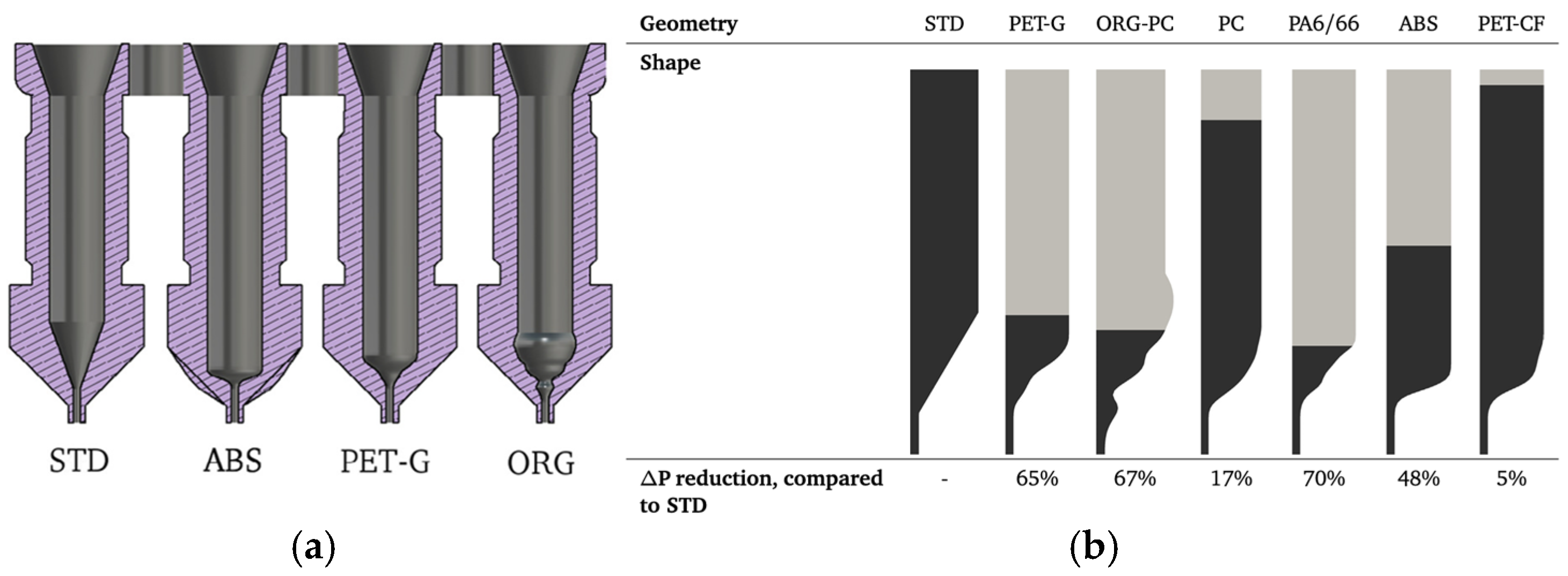
[43]MFPET-G, PC, PA6/66, ABS, PET-CFOpen FOAM, DAKOTAPressure drop, flow type, extrusion force.Optimized nozzle geometries reduce pressure drop and improve flow stability and control.Complex implementation in practice; variations in material behavior not fully addressed.
[44]CSPLACustom (LabVIEW), DMA, DSC, AFMNozzle/bed temperature, cooling rate, crystallinity, modulus.Improved adhesion with higher residence at 100–140 °C; mid-layers had higher modulus and compactness.Upper layer bonding is limited by cooling rate; model excludes local defects and complex geometries.
[45]CSABSAbaqusConduction, convection, radiation, deformation.Identifies conduction and convection as dominant heat transfer mechanisms.Neglects 3D effects: minimal impact observed from radiation and air convection.
[46]CSPLATemperature field, cooling rate, reheating.Shows reheating significantly impacts layer bonding quality.Porosity and radiation not modeled; geometry simplifications limit accuracy.
[47]CSABSAnsysTemperature, thermal conductivity, enthalpy.Highlights the influence of latent heat on thermal gradients and solidification.Simulates single-track only; complex geometries not included.
[48]CSABSTemperature, diffusion, wetting, bond strength.Model predicts bond strength based on temperature-dependent healing dynamics.Assumes ideal wetting; does not include geometric deformation.
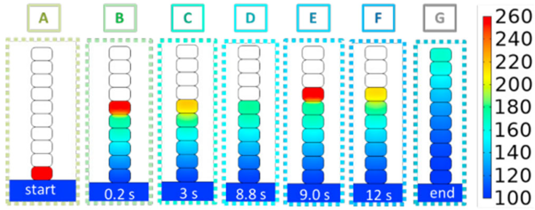
[49]CSABS, PEKKCOMSOL, IR cameraTemperature field, reptation degree, healing.Demonstrates that thermal contact dominates bonding; validated with IR data.Focuses only on early layer bonding; does not model long-term thermal behavior.
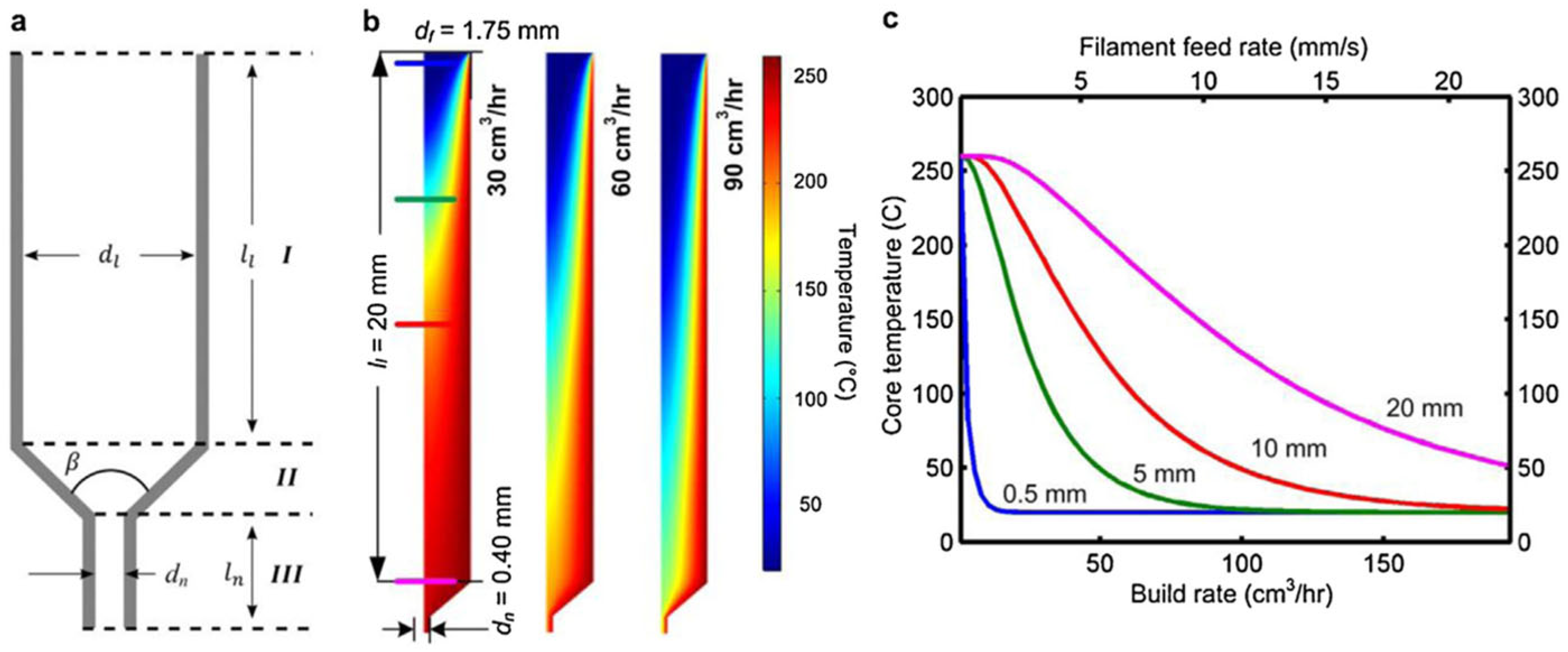
[50]CSABSCOMSOL, MATLABExtrusion force, heating rate, gantry speed.Heat transfer limitations restrict extrusion speed; system coordination is essential for performance gains.Lacks real-time thermal feedback and uses simplified material assumptions.
[11]CSPLAPython (ResNet), ArduinoNozzle offset, strain, delamination, warping.AI-based monitoring detects delamination early, enabling predictive quality control.Model trained on limited data; generalizability across materials and setups is untested.
[51]CSPLACustom (in-house)Shrinkage, stress, temperature, deformation.Captures cooling-induced shrinkage and residual stress in detail.High computational cost; does not account for viscoelastic material behavior.
[52]CSABS, PLAFLOW-3D, Open FOAMStrand shape, temperature, pressure, feeding rate.Simulates stable and unstable extrusion regimes based on pressure and flow patterns.Viscoelastic effects and complex geometries underexplored.
[53]TMBABSNumber of layers, section length, chamber temperature, shrinkage rate.Model quantifies warping and highlights the influence of chamber temperature and print path length.Assumes uniform material properties and constant speed; lacks validation for complex geometries.
[56]TMBPLA, Wood BiocompositeFLOW-3DResidual stress, temperature, distortion, defects.Model accurately predicts defects and residual stress; results validated experimentally.Assumes perfect bonding and uniform filler; coarse mesh limits defect resolution.
[57]TMBABSAbaqusDistortion, residual stress, mesh and timestep effects.Accurately predicts Z-direction distortion; results validated experimentally.Does not model anisotropy or plasticity; simplistic detachment modeling.
[58]TMBPA12DigimatTemperature gradient, residual stress, distortion.Highlights stress accumulation in lower layers due to cooling and reheating cycles.No experimental validation; simplified heat transfer and isotropic assumptions.
[62]TMBABSAbaqus, NCORR, Slic3rElastic modulus, yield strength, raster anisotropy.Accurately models anisotropic mechanical response; results agree with experimental data.Ignores bonding defects, filament-scale variations, and fracture mechanics.
[12]TMBPolymersMATLAB, FEAStrain, displacement, digital twin coupling.Digital twin enables real-time AM validation; supports predictive modeling of defects.Implementation complexity: integration with real-time feedback not yet streamlined.
[18]MPCPLA, ABS, PETG, Nylon, CF PLA and ABSInfill density, print temperature, fiber reinforcement, tensile strength, modulus.Fiber reinforcement and higher infill improve strength and stiffness; PLA–CF shows highest modulus (5.2 GPa).No standardized testing; limited insight into fatigue, creep, and environmental effects.
[24]MPCABS, FDCStructural integrity, defects, shrinkage.Highlights accuracy issues due to poor bonding and shrinkage in early FFF systems.Limited by hardware/software of early systems; findings may not generalize.
[59]MPCABS-M30Custom (in-house)Ultimate strength, stiffness, build direction, contour number.Model predicts tensile strength within ~4% of test data.Study limited to flat tensile geometry; excludes fatigue and impact performance.
[60]MPCPolycarbonateSolidWorks, AbaqusYoung’s modulus, shear modulus, Poisson’s ratio, stress distribution.Orthotropic model closely matches experiments; building orientation significantly affects performance.Plastic behavior is not captured; only linear elastic validation performed.
[61]MPCPLAMATLAB, CMM, TalysurfDimensional accuracy, flatness, surface texture, roughness.Layer thickness strongly influences geometric accuracy; ANN enables predictive tuning.Study limited to a single material and printer type; generalizability is low.
[65]MPCABSABAQUSStress–strain, fracture path, raster failure mode.Model replicates failure patterns; thinner layers show higher elongation.Assumes isotropy; excludes thermal effects and neck formation mechanics.
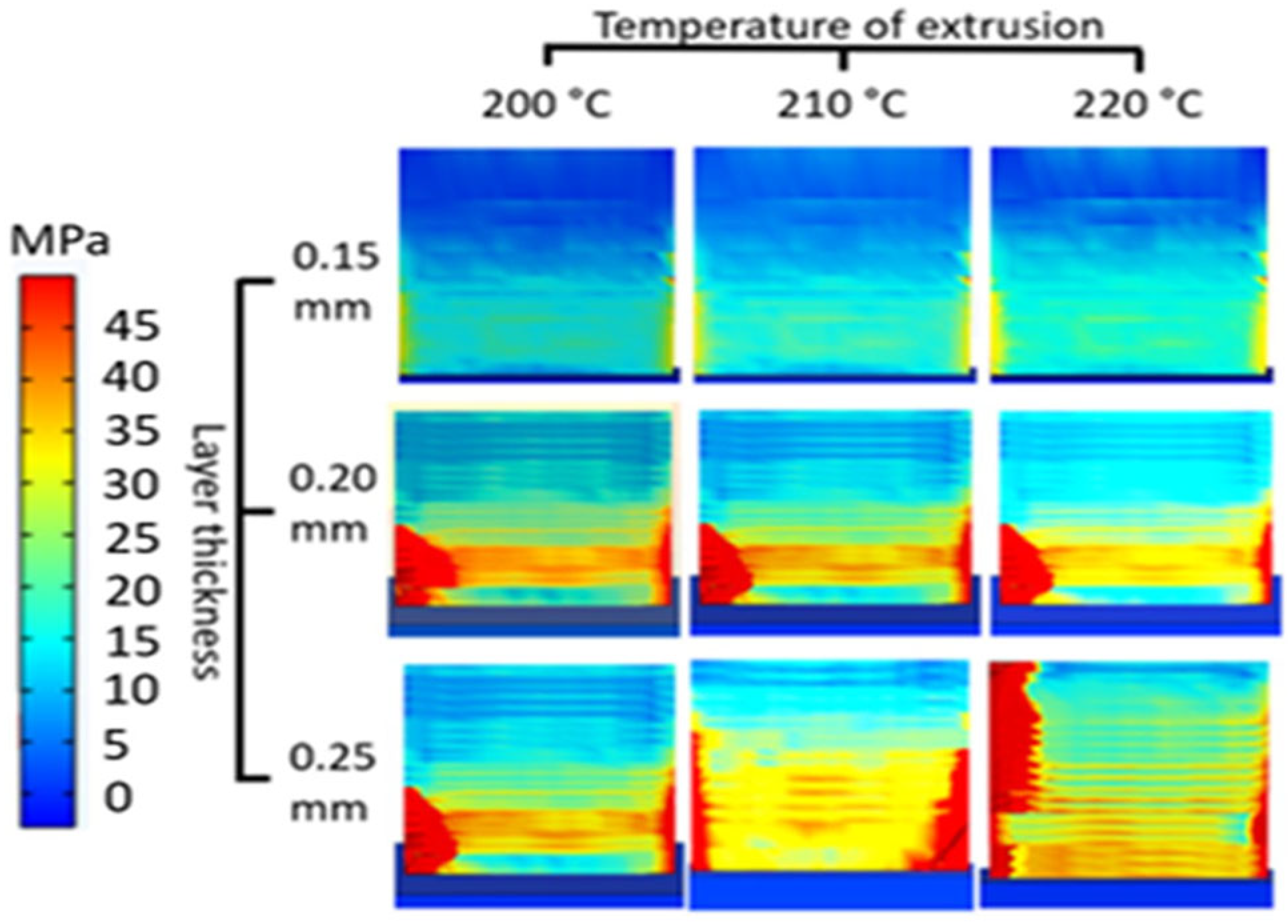
[73]MPCCF PPSABAQUS, Additive3DResidual stress, crystallinity, shrinkage, thermal conductivity.Model predicts deformation with <7% error; includes crystallization kinetics and anisotropy.Requires extensive experimental input; does not address creep or fatigue.
[5]FRCCF PolymerCustom (in-house)Flow alignment, shear, swelling.Coupling flow with orientation improves print accuracy and part quality.Nozzle flow simplified; high computational demands.
[6]FRCFRPViscosity, temperature, fiber effects.Summarizes key insights into melt flow and fiber orientation in composite FFF processes.Most models are uncoupled; validation data is sparse.
[7]FRCCF ABSAnsys Polyflow, MATLABOrientation, stiffness, nozzle effects.Nozzle gap and path significantly affect fiber alignment and part stiffness.Does not model fiber interaction; assumes Newtonian flow behavior.
[8]FRCCF ABSAnsys Polyflow, MATLABPressure, orientation, void risk.Low-pressure regions form around fibers, potentially increasing void formation.Only models single fiber; lacks full thermal coupling.
[37]FRCFRPCustom (SPH-DEM)Drag force, fiber deformation, flow.Models fiber alignment during extrusion with good correlation.Thermal effects excluded; limited to 2D simulation; lacks experimental validation.
[10]FRCCF ThermoplasticsFiber alignment, interlayer bonding, voids, anisotropy.Highlights design freedom and high strength potential of continuous CF composites.Challenges include fiber placement accuracy, void control, and limited toolchain/software support.
[67]FRCCF ABSOrientation, strength, modulus.Fiber alignment increases strength by 115% over neat ABS.Voids reduce toughness; print path has critical influence.
[68]FRCCF ThermoplasticsStrength, stiffness, alignment.Fiber content enhances stiffness; anisotropy linked to print path.Long-term mechanical behavior and standardization are lacking.
[69]FRCFRPCustom (SPH-DEM)Drag force, fiber deformation, flow.Predicts fiber orientation and flow behavior with good correlation.Excludes thermal effects; 2D model only; limited experimental validation.
[70]FRCCF PA66Amira, CFDFiber length, orientation, strength, modulus.Nozzle size influences fiber breakage: fiber alignment improves with build height.Neglects fiber interactions and complex geometries.
[71]FRCContinuous CF + PLACustom, FEAOrientation, voids, stiffness.Aligned paths reduce voids and increase stiffness by 30%.The method is computationally intensive and demonstrated only on simple shapes.
[72]FRCContinuous CF + PEKKCustom, μCT, FEAFailure strength, fiber deviation.Strength-based paths improve performance over stiffness-driven approaches.High computational complexity; limited geometry scope.
[76]FRCShort CF + ABSAltair Multi-scale DesignerFailure mode, stress, angle.Model accurately predicts anisotropic failure behavior.Requires calibration for each material-print setup.
Table 2. Software comparison based on specific criteria.
Software/CriteriaPotentialityUsabilityScalabilityAccessibility
AbaqusHighVery highHighHigh
AnsysVery highHighVery highHigh
Disclaimer/Publisher’s Note: The statements, opinions and data contained in all publications are solely those of the individual author(s) and contributor(s) and not of MDPI and/or the editor(s). MDPI and/or the editor(s) disclaim responsibility for any injury to people or property resulting from any ideas, methods, instructions or products referred to in the content.

