1. Introduction
Rare earth element (REE) is a general term for 15 elements in the lanthanide series in the periodic table of elements. Ion-adsorption rare earths are rich in the world’s scarce medium and heavy REEs. REEs are not rare in the Earth’s crust, but they occur in low concentrations, making them difficult to mine economically [
1]. As the global economy develops and technology advances, society’s demand for REEs, especially medium and heavy REEs, has surged. Their importance also extends to strategic considerations [
2,
3]. Technology’s reliance on rare earths means they play a key role in shaping the modern technological landscape and global sustainable development effort [
4,
5].
China is a country with abundant rare earth resources in the world. It has rich reserves and advantages such as complete mineral species and REEs, high rare earth grades, and reasonable distribution of mines. Medium and heavy rare earths are mainly distributed in southern regions such as Jiangxi, Guangdong, and Fujian provinces, where there are considerable ion-adsorption medium and heavy rare earth ores. More than 70% of medium and heavy REEs come from ion-adsorption rare earth ores. Due to their low abundance and limited reserves, medium and heavy REEs possess significant economic and strategic value. Consequently, they have been designated by the Chinese government as a mineral resource for protected extraction [
6].
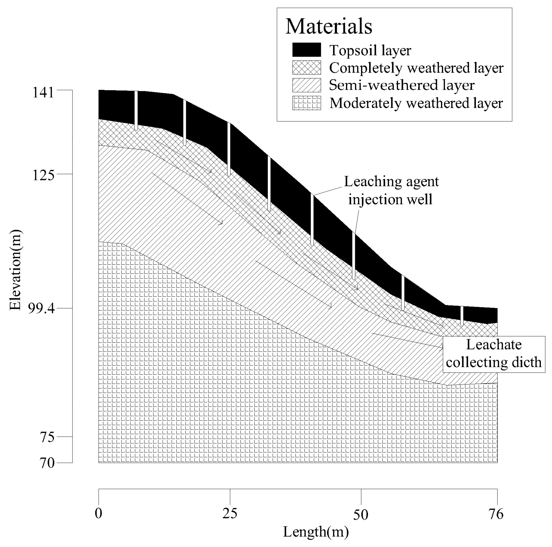
Ionic rare earth is typically found in the weathered crusts of granites and other igneous rocks. The ore body is distributed in layers within quasi-hilly regions formed by weathering, erosion, and scouring. From the surface to greater depths, the mountain where it is located is generally composed of a topsoil layer, a fully weathered layer, a semi-weathered layer, a slightly weathered layer, and bedrock. Rare earth ions are chiefly located in the fully weathered and semi-weathered layers.
Due to their highly stable nature, ion-adsorption rare earths cannot be extracted by traditional physical beneficiation methods such as magnetic separation or flotation. However, rare earth ions can be replaced by cations in electrolytes through exchange reactions. Currently, the in situ leaching techniques are the primary method for ionic rare earth mining [
7,
8,
9,
10]. (NH
4)
2SO
4 and MgSO
4 leaching solutions are commonly used for in situ leaching. Compared with (NH
4)
2SO
4 solution, the use of MgSO
4 leaching solution can reduce the environmental pollution caused by NH
4+. Therefore, the MgSO
4 solution is used as a leaching solution in the ion-adsorption rare earth mining area studied. The leaching reaction can be expressed by the following chemical Equation (1):
As shown in
Figure 1, the leachate is injected into the ore deposit through boreholes and injection wells, percolates, and migrates into the ore layer. Finally, the leachate saturated with rare earth ions is collected at the bottom of the ore body. The in situ leaching process of ion-adsorption rare earth mainly involves convection, diffusion, dispersion, ion exchange reaction, and adsorption and desorption of solutes.
In the in situ leaching of ion-adsorption rare earth, the landslides represent one of the most deadly potential safety hazards [
11,
12,
13,
14]. In recent years, research on the stability and deformation mechanisms of rare earth mine slopes has found that many factors affect the stability of slopes, such as the effect of water on soil mass, slope topography, and the properties of soil mass [
15,
16,
17,
18]. Particularly, the leaching solution significantly impacts slope instability and failure in rare earth mines [
19,
20,
21]. Jiang et al. [
22] analyzed the evolution of seepage fields, deformation fields, and slope stability during in situ leaching of a rare earth ore based on monitoring data. The results indicated that the intensity of leaching solution injection and the height of the seepage line are key factors affecting slope stability. During the in situ leaching process, large amounts of leaching solution are injected into the weathered layers of the mountain, increasing their liquid content. The displacement reaction of leaching solutions with rare earth ores diminishes the strength parameters of weathered ore layers, resulting in reduced stability and subsequent landslides [
23,
24]. Chen et al. [
25] employed FLAC 3D (Fast Lagrangian Analysis of Continua) software to simulate the effects of continuous leaching on pore pressure fields, displacement fields, and safety factors of a rare earth mine slope. Xu et al. [
26] applied the BP neural network and fuzzy comprehensive evaluation methods to study slope stability. Wang et al. [
27] intelligently predicted slope stability based on visual exploratory data analysis of 77 situ cases. Lin et al. [
28] compared several ensemble learning approaches to study slope stability, enabling more accurate predictions. Kardani et al. [
29] improved the prediction of slope stability using a hybrid stacking ensemble method based on finite element analysis and field data.
The above research indicates that the accurate slope stability analysis during in situ leaching is vital for safely extracting rare earth. Although a few studies have been conducted on this topic. Due to the rarity of ionic rare earth ores and the complexity and variability of specific engineering projects, it is necessary to further study the stability of slopes in these rare earth mines. In particular, the coupled effects of seepage and stress on the stability of rare earth slopes need to be further explored.
In this study, an actual rare earth mine engineering project in Cenxi city, China, was chosen to analyze. The SEEP/W, SIGMA/W, and SLOPE/W modules of Geo-Studio software were used to study the specific changes in the internal seepage field of rare earth slopes during dynamic leaching. Specifically, the transient analysis is first conducted using the seepage module to compute the seepage field of the slope during dynamic injection. Subsequently, the volume stress module is employed to couple the seepage field results and compute the slope’s stress and displacement fields under leaching conditions. In addition, the change law of the stability coefficient of slope under the action of seepage-stress coupling and potential failure mechanisms is analyzed. Finally, the optimal engineering control measures are designed to enhance safety and reduce costs, providing theoretical guidance for slope management in in situ leaching mining sites of similar ionic rare earth mines.
2. Methodology
2.1. Overview of the Studied Slope
The studied ion-adsorption type rare earth mine is located at northwest of Cenxi, China. The terrain of the mining area consists of low mountains and hills, predominantly oriented in a northwest direction. Elevations range from 100 m to 300 m, with valleys typically between 85 m and 150 m. The slopes are relatively gentle, with gradients usually less than 40°. These rare earth oxides are concentrated in the upper and middle sections of the granite-weathered crust, making the fully weathered layer the host for rare earth ore. The configuration of the ore body is heavily influenced by the terrain, undulating with the terrain, but to a lesser degree. The thickness of the ore body varies with its topographical position, and changes at the top, middle, and bottom of slope are stable: it is thickest in the middle of slopes with an average of 10.40 m, followed by the top slopes with an average of 10.06 m, and thinnest at the bottom with an average of 9.18 m. Generally, the central mining area, which is the initial mining area, shows a relatively greater average thickness. The ore bodies are positioned above the local erosion base level, and the terrain is conducive to natural drainage. No fault structures have been observed within the mining area. The hydrogeological boundary conditions are uncomplicated, with the ore bed resting on slightly weathered granite, which possesses strong water-blocking properties. The area has a well-developed surface water system characterized by rich vegetation and dense forest growth.
The physical and mechanical properties of soil and rock are important parameters [
30,
31] for calculating slope stability. Therefore, geotechnical exploration is essential to obtain the necessary parameters for verifying slope stability.
Figure 2 presents photographs from the selected geotechnical exploration sites. Based on the test results of soil mass samples from the survey area and referencing relevant standard requirements along with comprehensive experience, recommended values for the physical and mechanical parameters of the slope’s soil layers are provided in
Table 1.
Establishing the slope calculation profile is fundamental to building a geological model for slope stability analysis. A typical slope profile was selected through comparative analysis as illustrated in
Figure 3. The chosen in situ leaching model of the rare earth mine in this study measures 76 m in width and has a maximum slope height of 41.6 m, with slope gradients ranging from 29° to 42°. Field drilling identified four stratigraphic layers: topsoil, fully and semi-weathered granite zone, weathered layer, and bedrock.
2.2. Stability Analysis Method
The research methods of slope stability can be divided into five categories: limit equilibrium analysis method, numerical analysis method of stress and strain, reliability probability analysis method, graphical method, and modern analysis methods based on nonlinear science, such as neural network method, fuzzy mathematics method, etc. The limit equilibrium method is widely used because of its simple calculation and sufficient results to meet the of engineering needs.
The analysis methods of the limit equilibrium method mainly include the Fellenius method, the simplified Bishop method, the Janbu Simplified method, the Spencer method, the Morgenstern–Price method, etc., which are mainly divided into many methods according to the shape of the slope slip surface and the assumption of the force between slices. Because the safety factor value of slope arc failure is calculated by the simplified Bishop method, the Morgenstern–Price method and Spencer method can reflect the actual state of slope stability and have the advantages of fast calculation speed and reliable results, which are adopted by the majority of scientific and technological personnel, the above three analysis methods are the main methods of this stability research and evaluation.
The Bishop method is a method to modify the Swedish method, considering the effect of inter-strip force [
32]. In this study, the safety factors estimated for all potential failures are determined using Bishop’s simplified method, which is the most common method recommended in the design practice. In the method, the sliding surface is assumed as a quarter circle, and the foot of a certain slope is taken as the origin. The safety factors evaluated by Bishop’s simplified method are written in Equations (2) and (3), respectively.
where
is the gravity of the soil slice
i;
is the internal friction angle of soil slice
i on the sliding surface;
is the cohesion of slice
i in the sliding surface;
is the circular length of slice
i;
is the included angle between the tangent of the point in slice
i, circular, and the horizontal line.
The Morgenstern–Price method is a limit equilibrium method for slope stability analysis [
33]. The Morgenstern–Price method considers that there are normal forces and tangential forces between two adjacent soil strips. It is assumed that there is a certain functional relationship between the two forces in the horizontal direction, which can be expressed as Equation (4).
where
X is the tangential force between the soil strips;
E is the normal force between soil strips;
λ is an undetermined constant. When utilizing the Morgenstern Price method, the calculation result is the same as the simplified Bishop method.
The Spencer method is a rigorous limit equilibrium analysis method proposed by E. Spencer in 1967 [
34]. It adopts the form of total stress, satisfies the balance conditions of force and moment, and is applicable to any sliding surface. It assumes that the ratio of horizontal force to vertical force on both sides of the soil strip is constant, that is, the resultant force between each soil strip is parallel to each other. Then, the stability safety factor of the soil slope is solved, which is expressed as Equation (5).
where
Xi,
X1+i are the inter-strip forces in the vertical direction;
Ei,
E1+i are the normal inter-strip forces;
θ is the Angle of the force between the strips.
Geo-Studio, renowned as a premier geotechnical analysis software worldwide, features the SEEP/W and SLOPE/W modules. The SEEP/W is used to analyze groundwater seepage and pore water pressure dissipation. It provides comprehensive and straightforward analysis capabilities for issues ranging from simple saturated steady-state problems to complex transient problems involving both saturated and unsaturated conditions. The SLOPE/W is employed to study slope stability, applying limit equilibrium theory combined with finite element methods to address slope stability concerns [
35].
This study simulated the stability of rare earth mine slopes under in situ leaching conditions using the SEEP/W, SIGMA/W, and SLOPE/W modules of GeoStudio 2020 software. Initially, the SEEP/W module was employed to analyze the seepage characteristics of the rare earth slope under in situ leaching conditions, revealing the internal seepage patterns of the slope. The resulting seepage data were then imported into the SLOPE/W and SIGMA/W modules to analyze changes in the safety factor and displacement field.
2.3. Model Parameter Selection
In this study, the physical and mechanical parameters and permeability coefficients of rock and soil layers of the studied slope were comprehensively selected based on the results in
Table 1 and relevant specifications. Firstly, for the rock and soil layer above the water level, the physical and mechanical parameters are determined under the saturation conditions. The rock and soil layer below the water level is described based on the unsaturated conditions. Then, the permeability coefficient of the rock and soil layer was estimated by combining the results in
Table 1 and the volume water content equation provided by the SEEP/W module, by estimating the permeability coefficient equation. The SEEP/W module provides typical moisture content functions for various types of soils. Simply input the residual moisture content and saturated moisture content, and then select the corresponding soil sample to establish an unsaturated soil calculation model.
During the process of the in situ shallow well leaching method, leaching solutions are injected through injection wells, reducing the shear strength parameters of the weathered ore layers. Relevant studies [
36] have shown that in situ leaching reduced the internal friction and cohesive force of the weathered ore layer within 15 days, and after this period, it remains essentially unchanged. Therefore, the cohesive force and the internal friction of the slope materials need to be reduced in the limit equilibrium analysis. The 1.0~2.0% magnesium sulfate aqueous solution is used as a leaching agent in this leaching process. The parameter reduction scheme in this simulation is to reduce the cohesive force and internal friction of the fully weathered layer to 0.85 and 0.7 times before injection on the 5th and 10th days of injection, respectively.
2.4. Leaching Process
In this study, the simulations of slope stability were conducted in two stages. The first stage is that the leaching solution is injected into the ore body through an injection well. The second stage is the push-water operation, which is after the complete injection of the leaching solution. Water is injected into the leaching field to push out the rare earth mother liquor and some of the residual ammonium sulfate from the field. The injection volumes at various points were controlled according to the thickness of the ore body. The slope was divided into three leaching zones: the top, middle, and bottom of the slope. Initially, the leaching solution was injected into the uppermost leaching zone with a daily injection volume of approximately 100 m3. Five days later, the second leaching zone began injection, with the combined volume for both zones reaching around 200 m3 per day. The third leaching zone commenced injection 10 days after the first zone, resulting in a total daily injection volume of approximately 300 m3 when all three zones were injected simultaneously. Each leaching zone received about 100 m3 of solution daily over a total period of around 35 days, with the exact duration adjusted based on the ore body size. Following the push-water operation over the entire slope for 5 to 7 days, the water injection was incrementally stopped from the bottom of the slope to the middle, with a 5- to 7-day interval between each row. The overall duration of the push-water circulation was around 41 days. The total injection period of the two stages lasted approximately 77 days, including the leaching solution injection.
To accurately simulate the conditions of leaching solution injection and the push-water circulation, discharge boundaries were applied to the fully weathered layer, which is the primary host for rare earth minerals. Based on industrial test data, the discharge boundary for leaching solution injection and the push-water circulation were 3.31 × 10⁻⁷ m/s and 5.65 × 10⁻⁷ m/s, respectively. For solution recovery, a leachate collecting ditch was employed at the bottom of a slope, with a water flow rate boundary set to 0 m to simulate the outflow of the leaching solution.
2.5. Stability Grade of Rare Earth Slope
This study utilizes the safety factor obtained from the limit equilibrium method built upon finite element analysis to assess the stability of ion-adsorption rare earth mine slopes. According to the Chinese standard DZ/T0218-2006 [
37], stability is classified into four levels: unstable, slightly stable, basically stable, and stable (
Table 2). Here, F
s represents the safety factor calculated from the profile, and F
st denotes the allowable safety factor. This paper adopts F
st = 1.1 as the allowable safety factor for slope stability under in situ leaching conditions to ensure the slope’s stability and economic efficiency [
23].
3. Results and Discussion
3.1. Analysis of Seepage in Rare Earth Mine Slopes
According to the previously described model and relevant initial conditions, pore water pressure distributions in the rare earth mine slope during each injection period from 0 to 77 days were simulated using SEEP/W. The results illustrate the pore pressure distribution in the rare earth mine slope for each period, as shown in
Figure 4 and
Figure 5. It should be noted that these figures only present the change trend of different paremeters, not present the real situation on site.
Figure 4a illustrates the distribution of pore water pressure under the initial conditions (0 d), indicating that before the commencement of injection, pore water pressure gradually decreases from bottom to top along the groundwater level. Pore pressure is zero at the groundwater level, with the maximum negative pore pressure at the crest and the maximum positive pore pressure at the base of the slope.
Figure 4b–h shows the distribution of pore water pressure at different times during leaching. It could be found that as the injection period progresses, the leaching solution infiltrates further into the slope. The negative pore water pressure (matric suction) within the slope gradually diminishes, and negative pore water pressure across the entire weathered layer begins to rise. The area around the injection wells is the first to be influenced by the infiltration of the leaching solution, leading to a steady rise in pore water pressure. As a result, the contour lines become denser, and a high-pressure zone develops parallel to the slope surface. By injection of 30 days, this high-pressure zone has expanded to encompass most of the weathered mineral layers.
Figure 5 shows the distribution of pore water pressure at different times during the push-water operation of in situ leaching. It can be observed from
Figure 5 that the negative pore pressure in the fully weathered layer continues to increase, with the seepage line rising most rapidly at the bottom of the slope due to leaching solution deposition. As the injection period extends, the injection and recovery rates stabilize, entering a steady seepage phase where the seepage line remains largely unchanged except for small fluctuations in moisture content around the injection wells. Post-injection, the range of increased negative pore pressure on the slope widens, resulting in a higher likelihood and extent of instability. At this point, the seepage line rises to 32 m and intersects with the slope surface, with the downhill side of the intersection experiencing positive pore pressure. An increase in water level reduces effective stress. According to Terzaghi’s effective stress principle, effective stress mainly refers to the pressure between soil particles. When this pressure decreases, the friction between soil particles diminishes, reducing the soil’s shear strength and causing deformation (compression) and reduced soil strength.
Furthermore, on the one hand, the leaching solution infiltration causes the migration of soil particles, on the other hand, the leaching solution replaces the rare earth ions in clay minerals. This physical-chemical coupling effect of the leaching solution leads to the decline of soil shear strength. This greatly reduces the soil’s resistance to shear deformation and failure, significantly increasing the probability of slope instability [
38]. Additionally, the increased moisture content in the slope soil heightens its self-weight stress, thereby increasing the downward sliding force.
In the process of in situ leaching, the seepage line must be elevated to align with or even exceed the upper surface of the ore layer to enhance resource recovery. As a result, the injection intensity needs to be continuously increased; however, this may lead to greater deformation of the slope and potential landslides.
The primary failure mode of the slope in
Figure 4 and
Figure 5 is circle sliding, which occurs mainly in the topsoil and fully weathered granite layers. This shallow depth makes surface and mid-level landslides more likely. The physical and mechanical properties of the rare earth ore body soil deteriorate significantly during leaching. The permeability of the topsoil is markedly lower than that of the fully weathered layer. If the seepage line is not properly controlled during leaching, the leaching solution can accumulate within the topsoil, leading to saturation and a sharp decrease in shear strength. Under gravitational forces, the sliding mass experiences flow-plastic sliding along the interface between the topsoil and the fully weathered layer. This mechanism is the primary cause of topsoil landslides. As the leaching solution penetrates the highly permeable, fully weathered layer, the fine particles are stripped from the ore body by the leaching solution under dynamic water pressure and gravity, and will accumulate and rearrange within the pores formed by the coarse particles. In regions where fine particles concentrate, the ore body’s pores gradually become clogged, significantly reducing permeability. This leads to a corresponding decrease in effective stress with a continuous rise in pore water pressure. With the continued injection of leaching solution, the seepage line within the ore body expands further into the surrounding area, transitioning unsaturated zones into saturated zones and markedly decreasing shear strength. With good mobility within the fully weathered layer, the leaching solution gradually connects weakened sections of the ore body, forming a weak interlayer. Under the weight of the overlying soil mass, once the downward sliding force exceeds the frictional upslope force generated by the ore structure, the frictional upslope force generated by the ore structure, the slope is very likely to slide along this weak interlayer. This is the primary mechanism triggering ore layer landslides.
3.2. Effect of Liquid Injection on the Stability of Rare Earth Mine Slope
The leaching solution is continuously injected into the ore body through the leaching agent injection wells during in situ leaching. This process facilitates the exchange of cations in the ammonium sulfate solution with adsorbed rare earth ions [
39,
40]. During this process, the leaching solution causes fine particles to disperse and migrate from the top to the bottom of the rare earth mine soil, decreasing the local relative content of fine clay minerals. This alters the pore structure and pore size of the rare earth mine soil, further impacting its physical and mechanical properties. Consequently, the strength of the soil diminishes, and slope stability is compromised [
41].
Utilizing different analytical methods to compare the results of the safety factor enables a more reasonable prediction of slope stability. If the safety factors obtained by these methods show significant variation, it indicates issues with the engineering model. Otherwise, it confirms the model’s validity. Various methods, such as Bishop’s, Morgenstern-Price, and Spencer’s, were employed to study the transient stability of the rare earth mine slope under self-weight, groundwater, and injection conditions in this study. The Bishop method, grounded in Coulomb’s strength theory, employs circular slip surface analysis to simplify slope stability to a plane strain problem. A safety factor K is assumed, and it is then back-calculated. Iterative calculations ensure that the error in F is controlled within a specified range. The Morgenstern-Price method posits a functional relationship between normal and tangential interslice forces in the horizontal direction. It employs the slice method to analyze the forces acting on the sliding soil mass. The Spencer method posits that the ratio of horizontal to vertical forces on the sides of soil slices is constant, resulting in parallel resultant forces between slices. This method is used to determine the slope stability safety factor. The seepage calculation results from the SEEP/W module were input into the SLOPE/W module to determine the slope stability safety factors for saturated and unsaturated soils. This analysis revealed the changes in safety factors over time during the initial conditions and the main stages of leaching and push-water operation.
The comparison of the three analytical methods in
Figure 6 shows that the safety factors derived are largely consistent. This suggests that the influence of the calculation method on the slope safety factor is minimal. For instance, the results from the Morgenstern-Price method indicate that the safety factor of the rare earth slope decreases initially and then increases with the duration of leaching. Before leaching operations, the safety factor is 1.790. After 5 days, it slightly decreases to 1.753, showing minimal change from the initial condition. By 10 days, the safety factor drops to 1.663 as the leaching solution starts to weaken the geotechnical strength of the slope, significantly affecting stability. A sharp decline in the safety factor follows, attributed to the amount of leaching solution and the duration of injection increase, the moisture content in the soil significantly rises, creating extensive areas of high pore pressure. The leaching solution drastically reduces the slope’s cohesive force, and under high moisture content conditions, the soil’s shear strength mainly depends on the internal friction angle. Additionally, a substantial amount of the leaching agent within the slope increases the slope’s weight. The above analysis also indicates that the impact of leaching on the slope unfolds over time, exhibiting a certain degree of lag. The safety factor remains above 1.1 throughout the leaching process, indicating the stability of the slope. As the amount of push water decreases, the safety factor increases again.
3.3. Analysis of Stress–Strain Characteristics in Rare Earth Mine Slopes
Once the seepage field of the slope is determined with the Seep/W module, the results are transferred to the Sigma/W module to simulate the stress and displacement fields during the leaching process. According to engineering practice and research, the strain magnitude in the slope is key to analyzing slope stability. The position of maximum shear strain is generally where the slope is most susceptible to failure and where initial deformations appear.
Figure 7 and
Figure 8 display the maximum shear strain distribution during leaching in the slope. It is evident from
Figure 7 and
Figure 8 that the regions with the highest shear strain occur at the bottom of the slope, the middle to upper parts of the slope, the fully weathered granite range, and the interfaces between different layers. As the leaching progresses, these regions see a continuous increase in shear strain, eventually forming continuous shear strain zones that are susceptible to landslides. Consequently, the targeted landslide prevention measures are essential for these areas in in situ leaching mining operations.
The shear strength of soil can be effectively assessed through effective stress. This study simulates the changes in the effective stress field distribution within the slope’s soil mass. The analysis in this section is centered on the 15th day, characterized by the most significant deformation. The maximum and minimum effective principal stresses on the slope on the 15th day of leaching are shown in
Figure 9a,b. From the figures, it is evident that after leaching in the rare earth mine, reductions in effective stress on the slope primarily concentrate at the bottom of the slope, the middle to upper parts of the slope, and at the interface between the leaching agent injection wells and the ore-hosting horizon of deeply weathered granite layer, extends to the topsoil and the fully weathered granite layer, indicating that the influence of leaching on effective stress is predominantly localized in these areas. Overall, the results of the effective stress field demonstrate the overall stability of slopes in this study.
3.4. Analysis of Plastic Zone and Displacement Characteristics in Rare Earth Mine Slopes
The distribution of the plastic zone on the slope during the leaching and push-water operation is shown in
Figure 10 and
Figure 11. It should be noted that the yellow areas in
Figure 10 and
Figure 11 denote the plastic zones. As shown in
Figure 11, the result indicates that plastic zones develop at the top of the slope. As leaching progresses, large plastic zones emerge in the middle to upper parts of the slope and at the interface between the leaching agent injection wells and the ore-hosting horizon of the fully weathered granite layer. This can lead to the formation of tension cracks at the top of the slope. This phenomenon occurs because leaching starts from the top of the slope, allowing the leaching solution to infiltrate the mine through gravity and soil matrix suction. This results in a rapid increase in saturation and soil unit weight. The top of the slope is the first to experience the impact of permeate volume strength, causing soil particles to deform and displace along the infiltration path. In addition, the plastic zone within the fully weathered granite layer continues to expand with the leaching time. The leaching solution infiltrates along the slope towards the bottom, resulting in substantial permeate volume strength and increasing soil deformation. Because each layer’s interface, particularly between fully weathered and semi-weathered layers, represents a weak point.
The distribution of the plastic zone on the slope during the leaching and push-water operation is shown in
Figure 10 and
Figure 11. It should be noted that the yellow areas in
Figure 10 and
Figure 11 denote the plastic zones. As shown in
Figure 11, the result indicates that plastic zones develop at the top of the slope. As leaching progresses, large plastic zones emerge in the middle to upper parts of the slope and at the interface between the leaching agent injection wells and the ore-hosting horizon of the fully weathered granite layer. This can lead to the formation of tension cracks at the top of the slope. This phenomenon occurs because leaching starts from the top of the slope, allowing the leaching solution to infiltrate the mine through gravity and soil matrix suction. This results in a rapid increase in saturation and soil unit weight. The top of the slope is the first to experience the impact of permeate volume strength, causing soil particles to deform and displace along the infiltration path. In addition, the plastic zone within the fully weathered granite layer continues to expand with the leaching time. The leaching solution infiltrates along the slope towards the bottom, resulting in substantial permeate volume strength and increasing soil deformation. Because each layer’s interface, particularly between fully weathered and semi-weathered layers, represents a weak point. This causes the plastic zone to extend downward from the top along the slope, merging with the plastic zone at the interface between the fully weathered and strongly weathered granite layers. Additionally, the localized plastic zones developed at the bottom of the slope in the later stages.
Figure 12 shows the distribution of displacement after 15 days of leaching, it visually depicts the distribution and magnitude of slope displacement. As the leaching solution continues to be injected, it infiltrates from the injection wells through the topsoil to the fully weathered ore-hosting layer and even into the less permeable bedrock. During this infiltration process, the displacement changes in the slope are most pronounced in the middle to upper parts, decreasing gradually from the vertical slope inward. This suggests that tensile cracks may form in the middle to upper parts of the slope. Additionally, the ongoing leaching increases the downward sliding force on the upper soil mass, ultimately leading to the slope sliding outward and potentially triggering geological hazards.
During the initial leaching stage, the leaching solution in the slope soil was relatively limited, resulting in a slow exchange reaction between the leaching solution and rare earth ions. Consequently, the overall strength of the slope was minimally affected, maintaining stability. However, after 15 days of leaching, the moisture content in the slope substantially increased, and most weathered layers hosting the ore body were saturated with the leaching solution. This led to intense ion exchange reactions and, coupled with the self-weight of the solution, caused considerable displacement and further decreased slope stability.
3.5. Optimization Measures
Based on the slope instability mechanism revealed above and previous mining experience of in situ leaching mining for rare earth mines, it is evident that the leaching solution softens each soil layer of the slope, reducing the soil’s shear strength, specifically decreasing cohesive force, and increasing the likelihood of slope failure. Furthermore, the increased moisture content in the slope soil exacerbates the self-weight stress, enhancing the downward sliding force of the slope soil. Therefore, a well-optimal designed leaching solution injection plan can effectively prevent landslides of the slope. The studied Rare Earth Mine slope is divided into four stratified layers: topsoil, fully weathered granite, semi-weathered granite, and bedrock. The interfaces between these layers, especially between the fully and semi-weathered granite layers, represent weak points. Damage is mainly concentrated in the topsoil and fully weathered granite layer, where the depth is relatively shallow, making surface and mid-layer landslides more likely. The potential for slope failure increases during the mid to late leaching stages.
In summary, the following measures in
Table 3 can be taken to optimize the stability of ionic rare earth mine slopes. In addition, the advantages and disadvantages of various slope reinforcement measures are also shown in
Table 3. The intensity of the leaching solution injection is a crucial factor affecting slope stability and should be carefully regulated. Strengthen the slope displacement monitoring system, particularly during the mid to late injection stages. Focus on monitoring displacement in the topsoil and fully weathered granite layer, especially at the interface between fully and semi-weathered granite layers. Enhance the mine’s drainage and flood control systems. Based on the terrain and geomorphological features, strategically place leachate collecting ditches and tunnels to ensure the timely removal of leaching solutions and rainwater from the mine. Finally, additional reinforcement methods can be employed if the aforementioned measures do not meet safety standards or if the safety reserves of steep slopes are insufficient. These additional methods include the construction of retaining walls, anti-slide piles, slope surface reinforcement, slope cutting and unloading, and ecological slope protection.


 ,
, 


