1. Introduction
The adoption of mobile robotic systems continues to accelerate as application demands increasingly extend beyond the limitations of fixed workspaces, driving the need for greater deployment flexibility [
1]. This trend is evident across various domains, with the emergence of ground-based, aerial, and underwater robotic platforms. Several application areas include inspection tasks in oil and gas refineries [
2], radiation monitoring and mapping [
3,
4], underwater surveying [
5,
6], and operations in nuclear decommissioning environments [
6,
7].
One of the primary limitations to the sustained operation of mobile robots is the capacity of the onboard batteries, particularly in environments such as subterranean or reinforced concrete infrastructure, where access for maintenance is restricted [
1]. Traditionally, robots must either return periodically to a charging station or undergo manual battery replacement on-site [
1]. While these methods mitigate the battery constraint, they introduce significant operational downtime. An alternative approach is the use of tethered power and communication lines. However, this introduces further challenges, including entanglement, limited maneuverability around obstacles and added payload burden due to the tether itself thus reducing the system’s agility and operational scope [
8]. Alternatively, wireless power transfer (WPT) offers a feasible solution by enabling untethered energy delivery and potentially supporting continuous operation without physical connection or excessive intervention.
In terms of power levels and operating ranges, WPT technologies are most commonly applied to two distinct categories. High-power applications, such as electric vehicles, typically operate at kilowatt (kW) levels and rely on close-proximity coupling, with transfer distances generally under 0.3 m. On the opposite end, low-power systems are widely used for applications such as consumer electronics and medical implants, which operate at milliwatt to watt levels and over centimetre-scale distances [
9]. WPT is also employed in wireless sensor networks (WSNs), where ultra-low-power transmission can occur over distances extending to the kilometre scale [
10].
The source of power for these mobile robots is usually lithium batteries which can generally last for 30 min up to 8 h at most depending on the usage [
11]. Mobile robots are typically equipped with a set of payloads such as sensors, cameras, positioning systems and other necessary equipment designed for the assignment completion [
12]. Therefore, increasing the number of onboard batteries in mobile robots often presents challenges related to space constraints and weight limitations.
Table 1 shows the summary of parameters on the robot’s power and battery requirements where
P is the power consumption,
T is the operational time with the battery energy (
),
t is the robot’s charging time and
W represents the maximum payload of each robot. Husky and ANYmal are ground-based robots (UGV), Hydrus-300 and BlueROV represent autonomous underwater vehicles (AUVs), and Phantom 4 and Matrice 300 are examples of unmanned aerial vehicles (UAVs). The average power requirement for these mobile platforms is 100 W to 200 W, with an average operational time of 2.5 h based on battery capacity.
Among the various WPT techniques, inductive power transfer (IPT) remains a popular choice due to its relatively high efficiency over short to mid-range distances and its suitability for high-power applications [
17,
18]. In addition to IPT, capacitive-coupled wireless power transfer (CC) has also gained traction in recent years, particularly for short-range, high-power applications. Capacitive systems use electric field coupling between conductive plates to transfer energy, and are often favored for their compact form factor, reduced magnetic interference, and potential for high power densities [
19]. Despite these promising results, CC often requires precise plate alignment and high-voltage insulation, which can be challenging in flexible or deployable systems. In contrast, this study focuses on IPT due to its robustness to misalignment and its compatibility with mechanically reconfigurable coil geometries, which are essential for compact mobile robotic platforms. This is a critical consideration especially for inspection and maintenance in hard-to-access environments where minimal human intervention is required in autonomous operations [
20].
However, integrating IPT systems into space-constrained robotic platforms presents challenges. A fundamental trade-off exists between coil size and resonant frequency. Larger coils generally exhibit higher inductance, allowing for stronger magnetic coupling and better energy transfer at lower frequencies. Smaller coils operate efficiently only at higher frequencies, which may introduce increased losses due to the skin effect and parasitic capacitance [
21]. This trade-off becomes particularly critical when the coil must be compact during navigation and expand during charging, which requires both electromagnetic optimization and mechanical adaptability.
The recent literature has proposed various solutions to address coil alignment, efficiency optimization, and misalignment tolerance. For instance, double-D (DD) and DDQ coil configurations have been shown to improve lateral misalignment tolerance in EV charging systems [
22]. Other studies have explored adaptive coil arrays [
23], resonant repeaters [
24], and dynamic alignment tracking mechanisms [
25]. However, these solutions often assume a fixed coil geometry and do not address the need for compactness or reconfigurability. These are the key requirements for integration with mobile platforms.
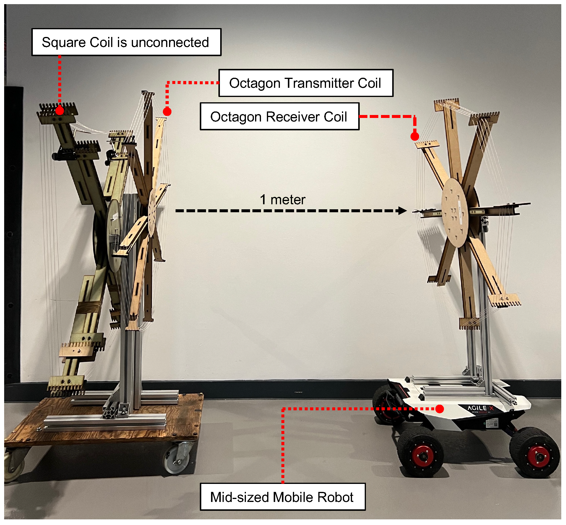
A prior work [
26] facilitates an octagon-shaped coil frame with a 1 m aperture diameter. It is capable of transmitting 109.7 W over a 1 m distance with 47.14% energy efficiency as shown in
Figure 1. Although the primary objective is achieved, the design size is impractical to implement onto a mobile platform in real applications. This paper addresses the space and payload constraints by introducing a robust and compact retractable WPT coil frame. We enumerate a range of retractable mechanisms, with considerations of minimizing the number of actuators, shortlist possible solutions, and select the optimal solution for the anticipated applications. The final design of the receiving coil is not of a rigid, regular shape; however, the theoretical and practical verifications prove that it does provide a sufficient amount of required power for a mid-range mobile platform.
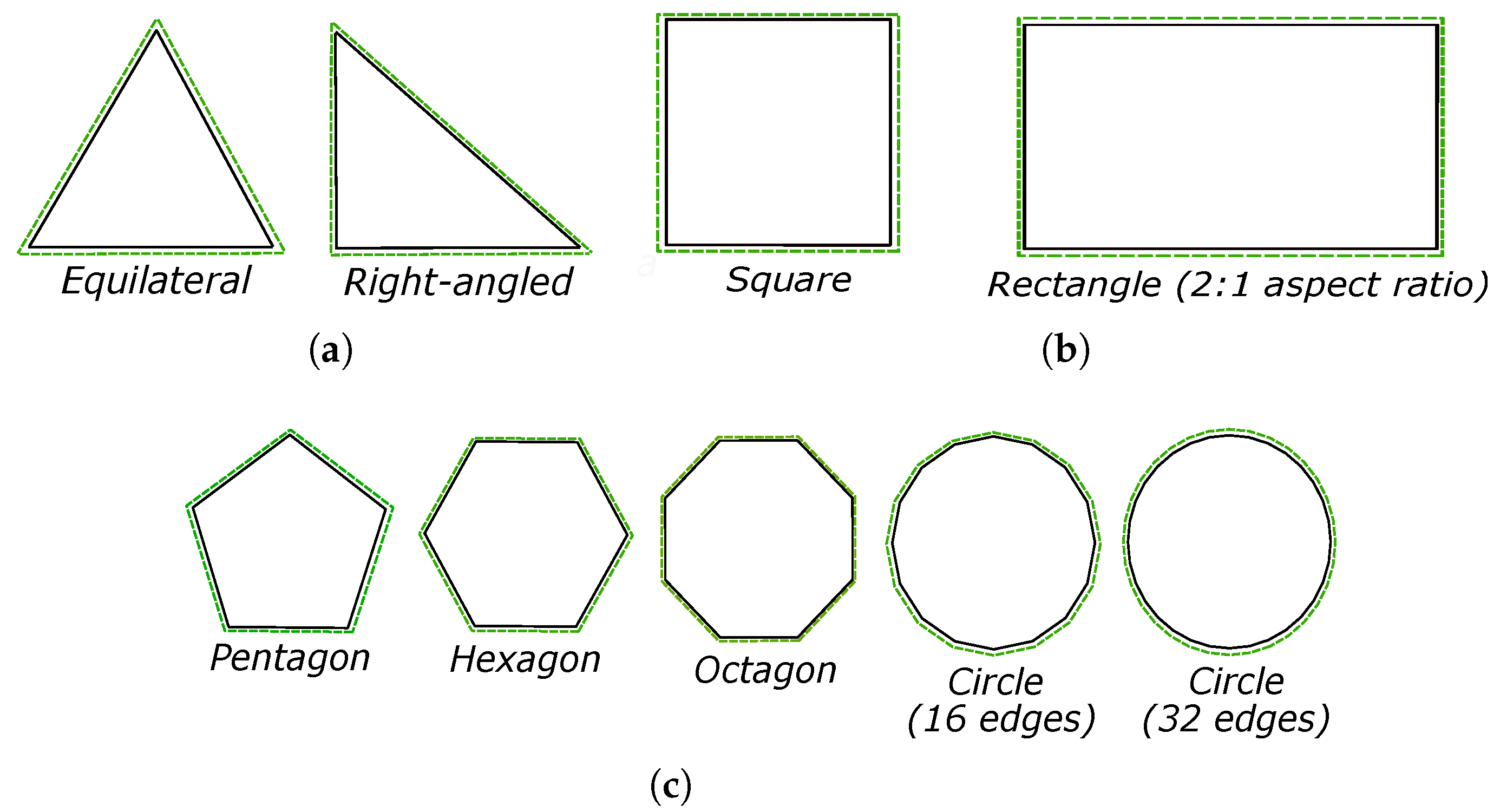
Figure 2 is the schematic illustration depicting the IPT transmitter and receiver regular polygon coils compared to irregular shape coils.
The following parts of the paper are organized as follows:
Section 2 elaborates the WPT system’s principles and shows the capability of power transfer performance with the iterations of coil geometry.
Section 3 presents the specification requirements for the coil designs and details the analysis of the WPT system modeling.
Section 4 discusses the experimental setup and measurements, and
Section 5 consists of the results, followed by discussions in
Section 6. Finally,
Section 7 concludes the study and sets the outlook for the future work.
3. Design and Simulation of Retractable Wireless Power Transfer Coils
3.1. Design Requirements and Conceptual Selection
The general objective of designing the retractable coil structure is based on the following assumptions: (1) the equivalent aperture area is similar, which is due to the nature of the magnetic field coupling mechanism, and (2) the thickness of the wires used remains the same so that the level of power transmitted, the energy efficiency, and the transmission distance are unaffected. The technical requirements are evaluated using a weighted decision matrix while maintaining the parameters used in the octagon-coil WPT system in [
26] (1 m circumcircle radius, 8 spokes, 5 turns, 0.75 mm cross-sectional radius coil). The overall score of the functions required by the design is determined using a five-level scale, which is divided into three categories:
Reconfigurability (Retractable): This represents the complexity of expansion-to-compression of the design. The design is rated from one to five, where one is the low complexity and five is the high mechanical complexity, which contributes to the coil reconfiguring process.
Coil Management: This assesses the WPT coil management in terms of storage while the design is in a fully compressed position and coil handling during the expansion process (one being less likely to tangle, and five representing the high potential of coil entanglement).
Mechatronic Complexity: This is divided into two sections, which are mechanical and electrical. The mechanical complexity score represents the number of movable joints involved during the reconfiguration. Electrical complexity represents the number of electrical actuators that would be involved in the motion.
Each design is evaluated according to the proposed conceptual designs shown in
Figure 4. The design is scored based on the results of the comparison, which are displayed in
Table 2.
Design 1 (Sunshade Folding): This design uses actuators inspired by car sunshade folding using a lightweight structure with the wireframe as the coil frame’s outer lining. The challenges are effectively installing and positioning actuators to replicate the folding motion.
Design 2 (Rotation Folding): The frame collapses via a motorized function for efficient expansion and storage. This method promises better space efficiency but raises concerns about coil management during collapse.
Design 3 (Two-piece Folding): Its two half-frames are designed to collapse into a smaller size, and the octagon-shaped frame structure folds horizontally. It uses a telescopic stand to lower closer to the base for vertical retraction.
Design 4 (Telescopic): A telescopic design for the coil frame using motorized gears. This non-foldable design may contribute to a higher mass, as all arms are within one structure. The extension method is possible with motorized linear motors with gears.
Design 5 (Umbrella): An umbrella-skeleton collapsible frame. The challenges are potential coil entanglement within the frame due to the design complexity with multiple movable joints.
Design 6 (Scissor-linkages): Two arms are positioned on the left and right sides originating from the center of the body, using the scissor-linkages concept to form a geometrical shape frame holding the coil.
Table 2 shows the design matrix for all six conceptual designs. The matrix considers the complexity of the coil reconfiguration and coil management to prevent any entanglement of the coil during the retracting and expanding motion. The score weight represents how the concepts respond to the functional needs, taking into account the utility or importance of the functions with the design target’s overall need. The design selection is based on the overall score; the higher score represents the high design complexity, high coil entanglement, higher number of movable joints and actuators involved in the process of design development. This decision aims to identify a design that minimizes mechatronic complexity while contributing the least possible mass to the payload of the mobile platform. Based on the decision matrix table, the sunshade folding design proves to be more complex and scissor-linkages comes out on top as the less complex design. The sixth conceptual design (scissor linkages) has been selected as the best option based on its potential for forming shapes and the three design specification criteria.
3.2. Simulation Methodology
A series of simulations were conducted using IPTVisual to evaluate the electromagnetic performance of different winding geometries in the proposed retractable WPT system. IPTVisual is a specialized software tool developed for efficient modeling and visualization of spatial energy flows in arbitrary-shaped inductive power transfer (IPT) coils [
21].
IPTVisual was selected for its ability to simulate mid-range WPT systems with complex coil geometries using a lightweight, script-based approach. It supports arbitrary winding shapes by allowing users to define trajectories through key spatial coordinates. These coordinates were discretized into segments matching the wire diameter to enable high-resolution modeling of inductive and resistive effects. This segmentation approach provides sufficient accuracy in the calculation of self- and mutual inductances using Neumann’s formula, with performance validated against analytical and FEM-based methods.
In the simulation setup, each winding was treated as a discrete circuit element, which could be driven by a constant voltage. Compensation capacitors were included to enable resonance at a single operational frequency. Parametric modeling was carried out across a range of winding geometries configurations with the corresponding coil parameters such as number of turns, turn radius, and spacing systematically varied.
The solver engine in IPTVisual employs complex impedance matrix formulations to solve for circuit voltages and currents across all nodes. Both amplitude and phase information are retained, which allows the accurate computation of real and reactive power, as well as visualization of the energy flow using Poynting vectors. These energy flow vectors were sampled across a three-dimensional spatial grid and rendered using WebGL to identify high-coupling regions, losses, and the influence of misalignment.
3.3. Parametric Analysis of Coil Geometries
Three subcategories of geometric shapes of WPT coils were selected as shown in
Figure 5. Group 1 represents the triangle group (equilateral and right-angled). Group 2 includes quadrilaterals, squares, and rectangles with a 2:1 aspect ratio. Group 3 consists of polygons such as pentagons, hexagons, octagons, and circles with 16 and 32 edges.
Table 3 presents the simulation results for the groups of coil shapes under a fixed input power of 200 W (where
N represents the coil’s number of edges). Observations were made on the WPT system’s coil resistance (
), mutual inductance (
M), coupling coefficient (
k), transmitted power (
), and energy efficiency (
).
The across different WPT coil shapes is varied. While the coil cross-sectional area () remains consistent across all shapes and the coil diameter () or aperture size is maintained at 1 m, the coil length is adjusted. This variation affects self-inductance, which in turn influences both the transmitted power and energy efficiency. Based on the simulation results, square-shaped coils achieve the highest energy efficiency (90.67%), followed closely by pentagon, hexagon, octagon, and circular coils, while triangle and rectangle shapes perform significantly worse. This is mainly due to better area-to-perimeter ratios and more uniform magnetic flux distribution in compact, symmetric shapes. In summary, other shapes could perform better; however, based on basic physics (area-to-perimeter ratio and field uniformity), the simple compact shapes (squares and circles) are already very close to optimal. Fine-tuning shapes, such as rounding edges, adjusting polygon sides, or using hybrid designs, could bring small further improvements, but dramatic changes beyond approximately 91–92% efficiency are unlikely in practice.
This parametric analysis directly informed the final design decision. The square coil geometry was selected due to its optimal balance between electromagnetic performance. It demonstrated a high coupling coefficient and energy efficiency and mechanical compatibility with the retractable scissor-linkage mechanism. The simulation results guided both the physical implementation and the subsequent experimental validation.
3.4. Formation of Figure of Merit
In assessing different WPT coil shapes for mobile robots, a figure of merit (FOM) is created to gauge the energy efficiency, the coil misalignments, and its feasibility for practical implementation. FOM derivation from the metric components alongside their respective weights can be presented in Equation (
9). The cumulative sum of these weights equals 1, serving as a normalization technique. The pivotal factor lies within Metric A (
), wherein the WPT performance heavily relies on the fundamental parameter of the WPT followed by Metric B (
) and Metric C (
):
Metric A (power related): This represents the assessment on energy efficiency and output voltage:
where
and
d are weights assigned to each component.
W is a measure based on the coil parameter (
L,
M,
R, and
N).
evaluates the output power,
evaluates the energy efficiency, and
evaluates the output voltage relative to the target.
Metric B (dimension related): represents the evaluation framework based on the described dimension-related aspects:
These weights assigned (, and g) to each component should sum up to 1. , and are normalized scores or factors representing the evaluation of the number of coil edges, coil shape ratio defined by dividing the area of a coil shape by its perimeter, and compression ratio of fully extended to fully retracted, respectively.
Metric C (mass related): This captures the overall evaluation based on mass-related considerations, combining the calculated coil mass, coil weight, and a measure of coil management ease or difficulty into a single metric:
and l are weights assigned to each component. is the calculated mass of the coil based on the perimeter and number of turns, is the weight of the coil, and forms are graded on a scale from 1 to 10, indicating the ease or difficulty of managing coil entanglement during extension and compression states.
Figure 6 illustrates the relationship between the component metric concerning individual weight, highlighting the optimal choice in selecting the geometric coil shape based on the previously described linear aggregation method. The square coil shows the highest score among other coil shape variations with a score of 9.73.
3.5. Misalignment Sensitivity and Performance
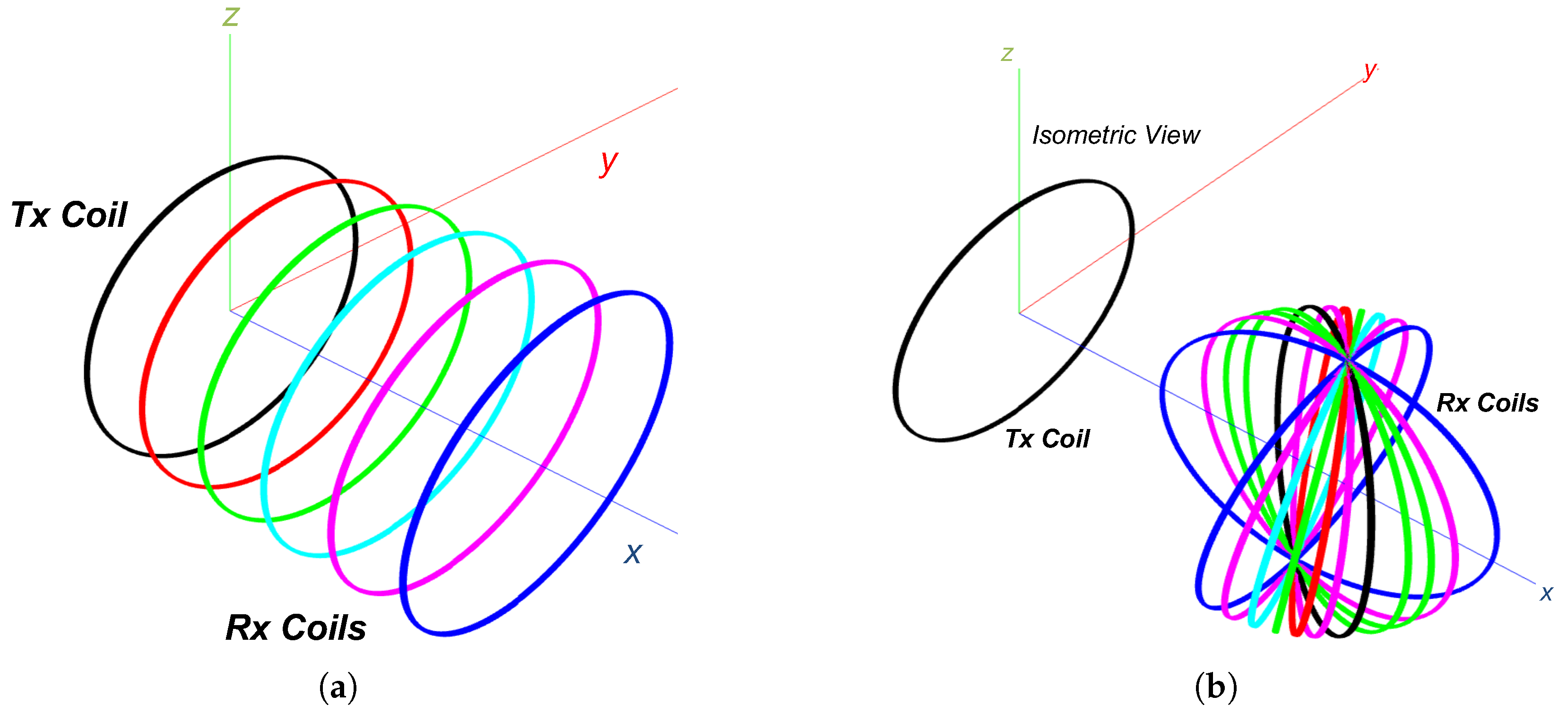
Misalignment is a critical factor that significantly influences the efficiency of WPT systems, especially in mobile or dynamically positioned applications. In this study, the performance of the proposed square coil design is evaluated under two primary misalignment scenarios: lateral displacement and angular deviation. These analyses are conducted using simulation tools prior to experimental validation to assess the robustness of the electromagnetic coupling under realistic operating conditions.
Further study assesses the linear and angular misalignment based on the geometrical configurations of WPT coils with different edges, which are determined as
N.
Figure 7 depicts the setup for both conditions.
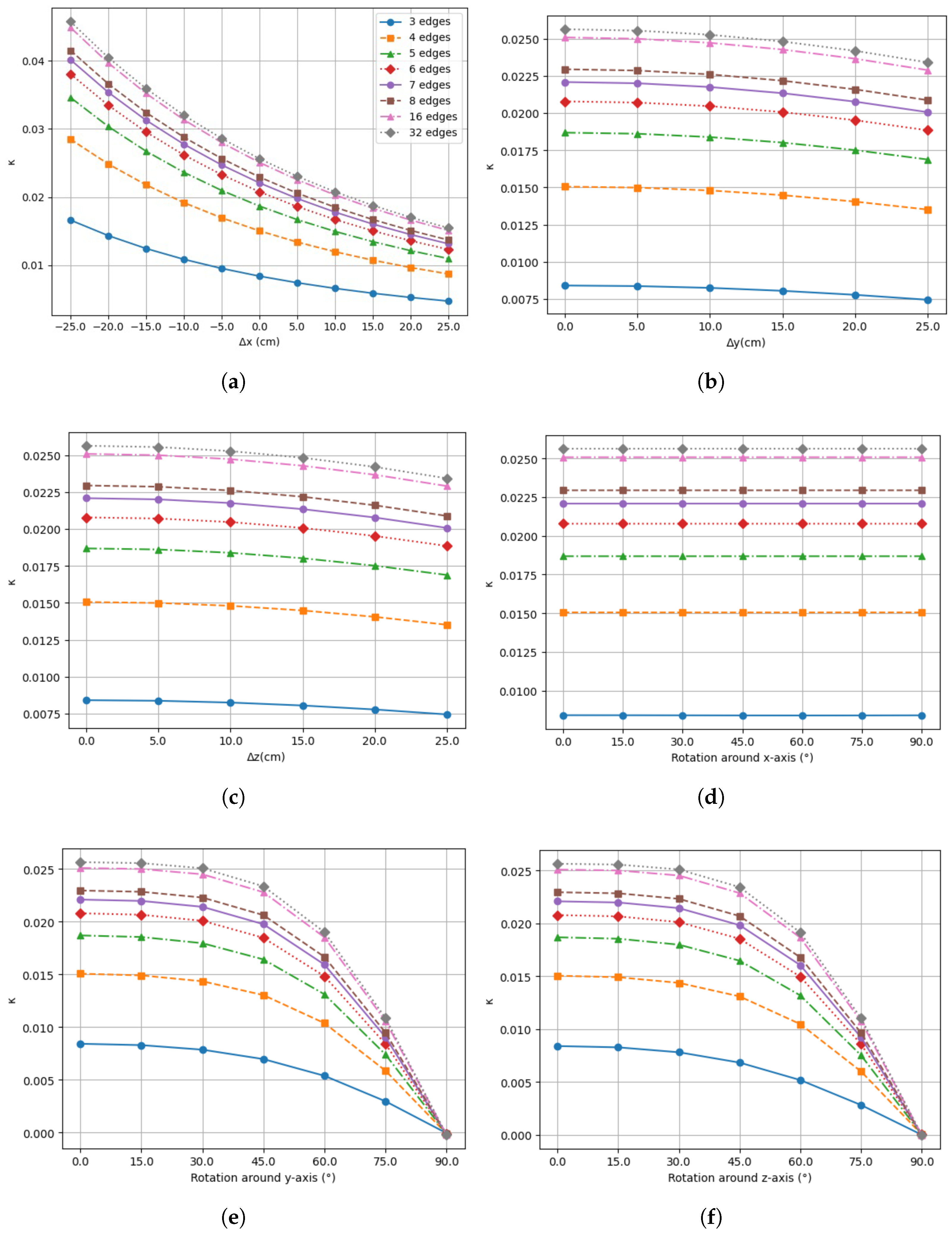
Figure 8a–c show the linear misalignment of the different WPT coil shapes. As the distance between the transmitter coil (Tx) and receiver coil (Rx) increases,
k will also decrease, indicating the decrement of the coupling point between these two coils along the x—axis. Translation along the y— and z—axes shows a slight impact on
k when Rx is positioned accordingly. Linear misalignment along the x—axis shows a significant reduction in
k compared to the other two axes. The observation on angular misalignment presented in
Figure 8d–f shows that the rotations along the x—axis have minimal impact on
k. The rotations along the alternative two axes significantly decrease the coupling coefficient, implying a decrease in system performance under angular misalignment conditions.
These findings highlight the importance of alignment control in reconfigurable WPT systems. While the square geometry offers practical advantages for mechanical deployment, its sensitivity to misalignment presents a challenge for real-world use. This emphasizes the need for further design refinements, such as adaptive alignment mechanisms, flux-guiding materials, or alternative coil topologies with improved tolerance to spatial variations.
3.6. Impact of Structural Materials
In practical implementation, the presence of metallic structural components near the WPT coils such as elements of the retractable scissor-linkage frame or the robot chassis can significantly affect the electromagnetic performance of the system. These nearby conductive materials may induce eddy currents when exposed to alternating magnetic fields, leading to additional energy losses, the distortion of magnetic field distribution, and undesirable thermal effects. While the current study primarily focuses on validating the mechanical feasibility and electromagnetic performance in ideal conditions, the integration of metal structures warrants further investigation.
In a recent study [
34], a comprehensive analysis of thermal risks in wireless EV charging systems under spatial misalignment was conducted, illustrating how metallic components can exacerbate local heating and reduce system efficiency. Although the study targets higher power EV applications, the modeling approach and analysis of dynamic spatial variation are directly applicable to WPT systems in mobile robots. Future development of the retractable WPT system will consider such effects through electromagnetic and thermal simulation, with the aim of introducing material shielding strategies or structural redesigns to mitigate performance degradation caused by metallic proximity.
3.7. Integration with Mechatronic Design
The mechatronic design selection can be analyzed based on the simulation results. Among all six conceptual designs proposed in
Table 2, three candidates are proved to be practical in terms of the criteria presented in the conceptual design matrix table namely Design 4 (telescopic), Design 5 (umbrella), and Design 6 (scissor linkages).
The simulation results show that the optimal selection on the WPT coil shape to transmit the highest power with high energy efficiency is either in Group 2 (4-sided coils) or Group 3 (other polygons) in
Table 3 with 90% energy efficiency at the output of the WPT system. The magnetic coupling achieved with a circular coil (
N = 32 edges) of the same area is slightly greater than that of square and rectangular coils. This is likely due to distortions in the field distribution near the corners of the latter shapes. With reasonable accuracy, these results suggest that the primary factor influencing magnetic coupling is the area enclosed by the inductor, while the coil’s exact shape has only a minor effect. The results are simulated in an ideal environment with minimum power losses and disturbances.
Nevertheless, the potential forming shape is another factor contributing to the mechatronic design selection. Design 6 is capable of forming four shapes (hexagon, pentagon, square, and triangle). Regarding mechatronic complexity, although the number of mechanical joints in the scissor linkage is considered numerous, it could be balanced with the minimum actuator required to move the whole body. Electrical DC motors could be installed to move the scissor linkage into the desired form. Among the four potential forming shapes stated for the scissor-linkage concept, the square coil is proven to be the best candidate in terms of transmitted power (181.33 W) with an energy efficiency of 90.67%, followed by pentagon, hexagon, and triangle. In summary, it can be concluded that the square coil is the best candidate for a retractable WPT.
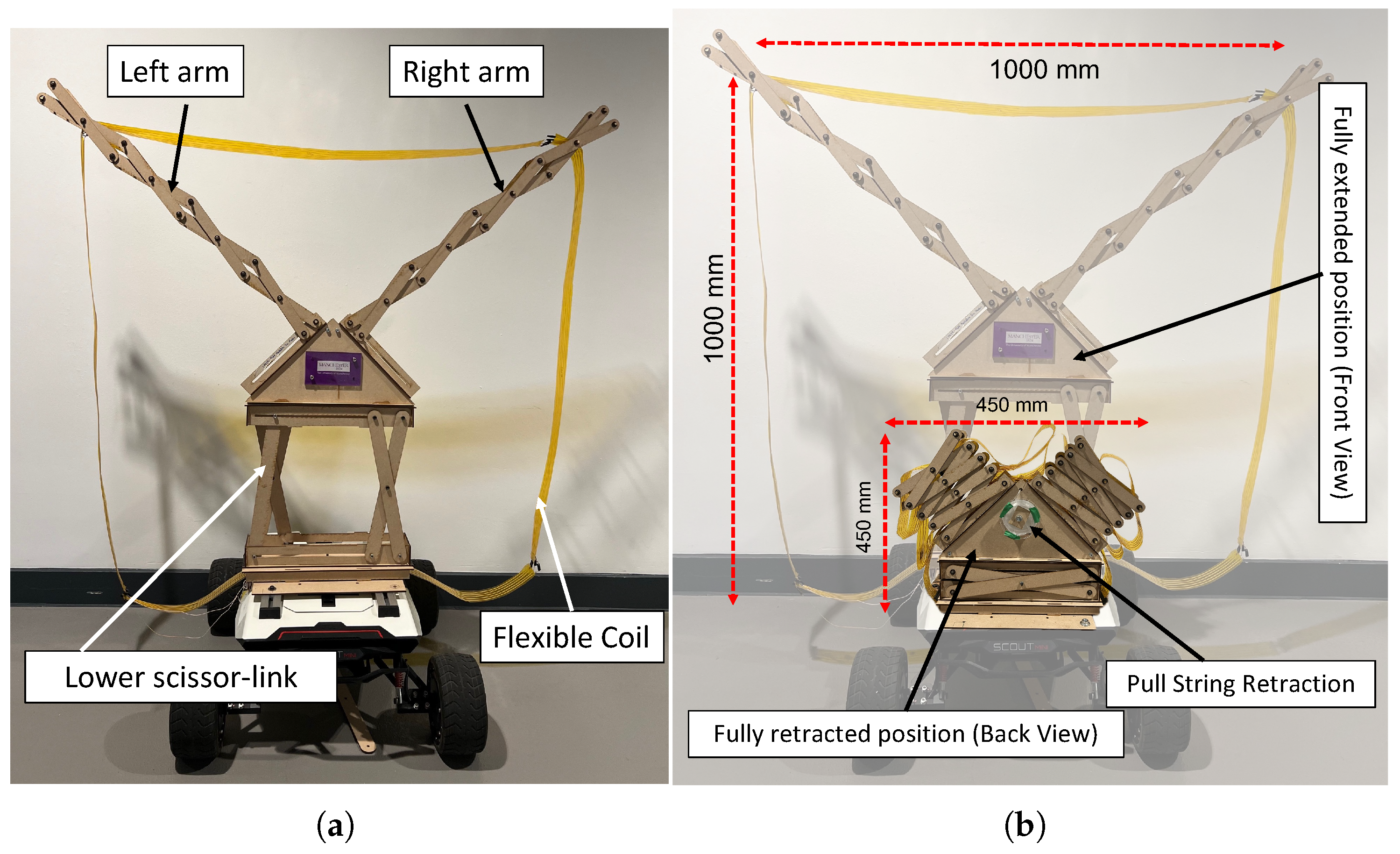
In this study, Scout Mini is chosen to provide insight into the practical implementation of the proportional relationship between the coil frame’s size and the mobile robot’s. The width and length of the square coil are set to be 1 m and positioned on the top of the mobile platform.
Figure 9a,b depict the comparison between the fully extended and fully retracted positions of the Rx coil on a mid-sized inspection robot (Scout Mini). Addressing the coil management issue, the flexible coil is fixed with string points which are essentially wound up using the pull string retraction mechanism mounted at the center back of the coil structure. The maximum retracting position is measured at 450 mm × 450 mm (4.94:1 compression ratio).
4. Experimental Setup and Measurements
A series of laboratory-based experiments were conducted to validate the performance of the proposed retractable WPT system. These experiments aimed to characterize the system’s energy transfer efficiency under various alignment conditions and to compare the empirical results with simulation predictions.
All measurements were performed in a controlled indoor laboratory environment at a stable ambient temperature of 22 ± 1 °C. The tests were carried out away from metallic infrastructure and high-frequency switching equipment to minimize electromagnetic interference. Both the transmitter and receiver coils were supported on non-conductive platforms to ensure accurate magnetic coupling. For angular misalignment tests, the receiver coil was mounted on a rotatable platform with angular markers, enabling consistent adjustments with a tolerance of ±1°.
The instrumentation setup included a digital oscilloscope for voltage and current waveform acquisition, combined with a Rogowski coil for current sensing and high-voltage probes. The oscilloscope has an accuracy of ±1% for RMS measurements. A precision LCR meter was used to measure the self-inductance and mutual inductance of the coils, with an accuracy of ±0.5%. Distance offsets were measured using a digital caliper with ±0.01 mm resolution, while the coil positioning was guided by physical alignment jigs to reduce operator error. The ID of the components from manufacturers are listed in
Table 4.
Each measurement was repeated three times under identical boundary conditions. The average values of the repeated measurements were reported, and standard deviations were used to indicate data variability. For results involving critical parameters such as energy efficiency and mutual inductance, error bars representing ±1 standard deviation are included in the corresponding figures in the next section. These repetitions were essential for mitigating random variation introduced by minor mechanical instabilities or probe repositioning. Measurement uncertainty was analyzed using a first-order error propagation method. The cumulative uncertainty in energy efficiency was estimated to be approximately ±2.5%, considering the voltage, current, and phase measurement accuracies. For coil inductance values, measurement uncertainty remained within ±0.5% as reported by the instrument specification.
Litz wire was used as the main material of the coil and wrapped around the coil frame in five turns. The gap between each turn of the coil was designed to be approximately 10 mm apart to reduce the skin effect. The coil turn was held together with Kapton tape for coil management, reducing entanglement during extension and retracting the motion of the retractable square coil (SC—WPT).
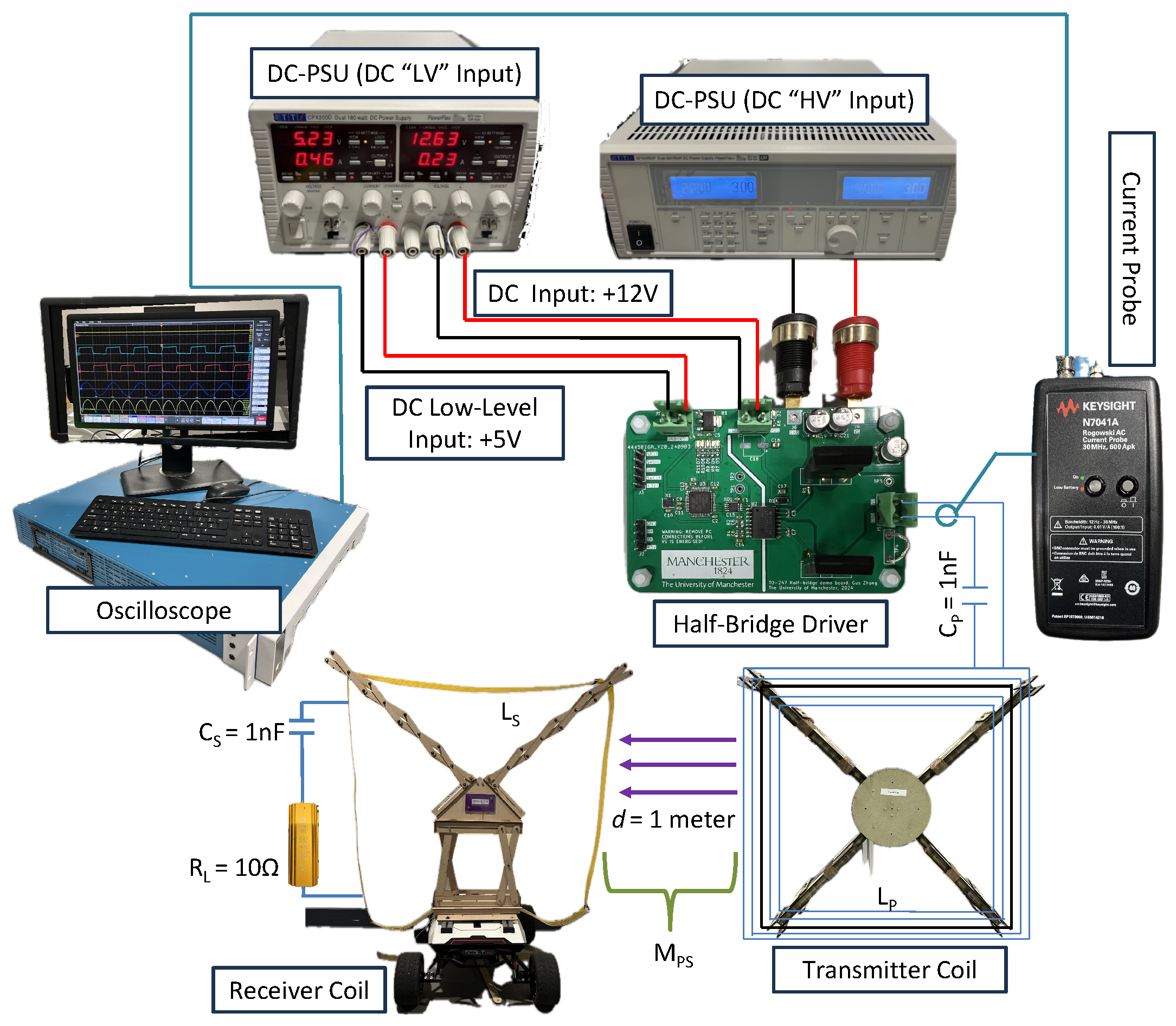
Figure 10 shows the abstract of the experimental setup using a half-bridge driver board connected to the SC—WPT system. Both Tx and Rx are set to be square coils, with Tx being a fixed square coil, while Rx is the retractable square coil.
,
,
, and
are the compensation capacitors, and self-inductance for primary and secondary coil, respectively.
is the mutual inductance. The lateral misalignment
d is set to 0.4, 0.6, 0.8 and 1.0 m along the x—axis. The angular misalignment is set to
,
,
,
, and
around the z—axis. The lateral misalignment for this setup is kept constant at
d = 1 m.
5. Results
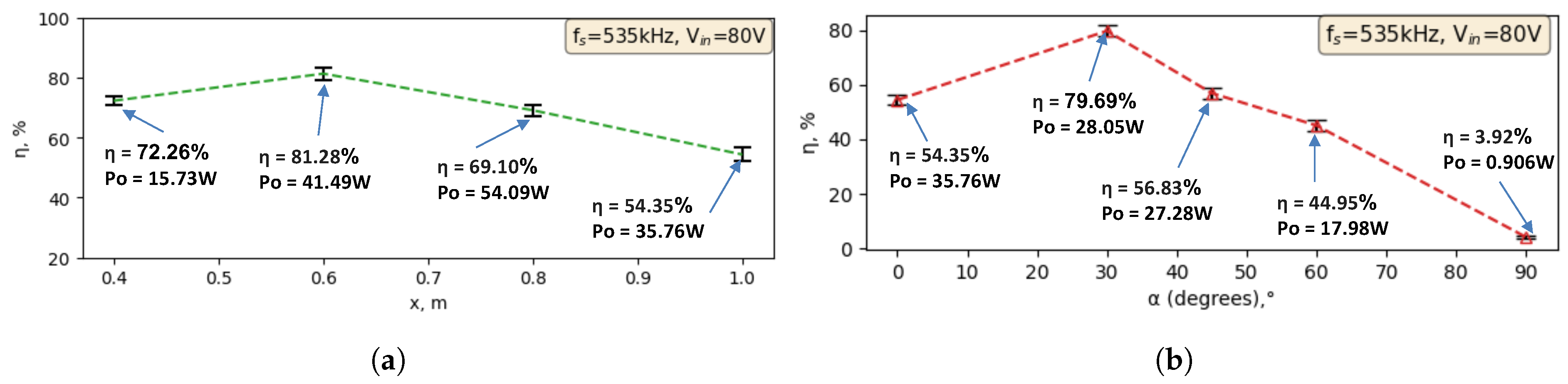
Figure 11a,b show the experimental results of energy efficiency during lateral and angular misalignment where the WPT system is operating in resonance frequency of 535 kHz and input voltage of 80 V.
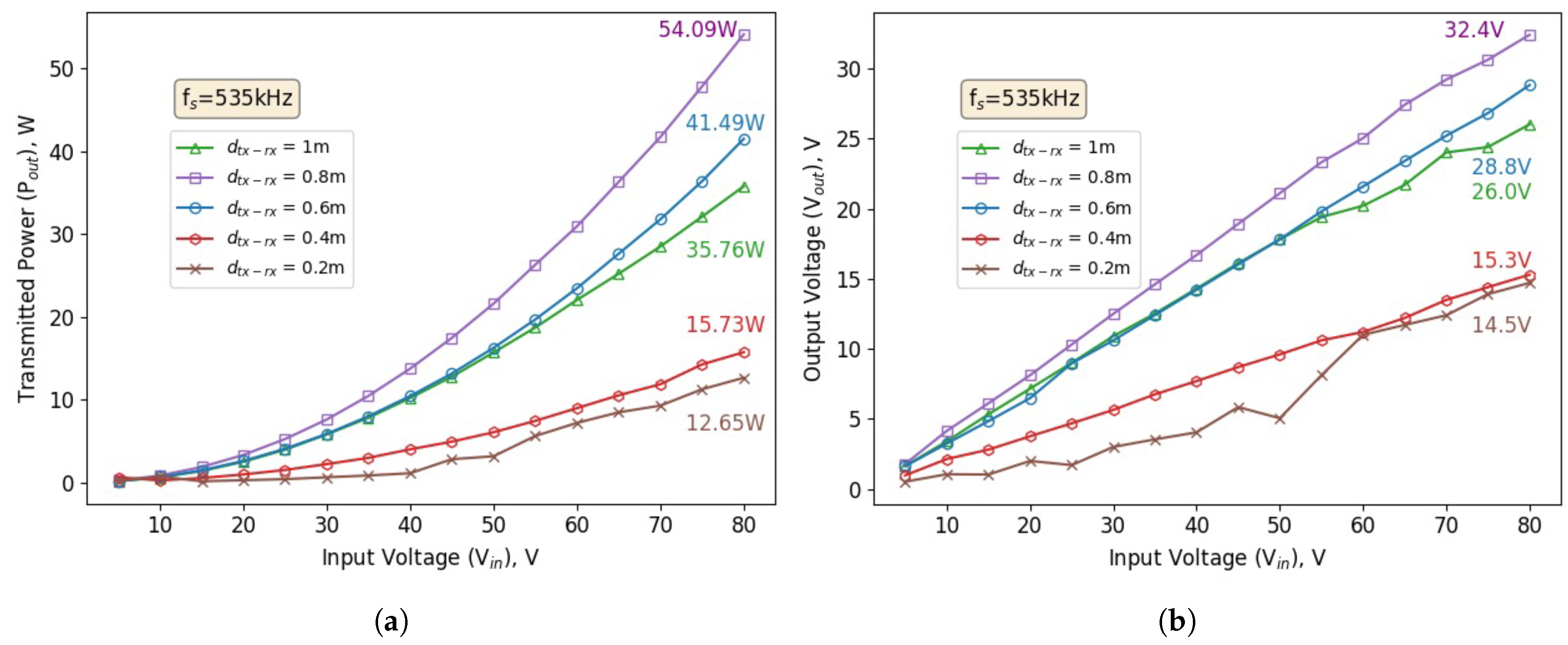
Figure 12a depicts the transmitted power when the half-bridge driver board is gradually supplied with input voltage up to 80 V. The Tx and Rx coils are tested with distance variations. The result shows the capability of the SC—WPT to transmit 35.76 W of power at a distance of 1 m apart from each coil. The highest transmitted power is when the distance is at 0.8 m (54.09 W).
Figure 12b shows the corresponding output voltage measured across a load resistance of 10
with the highest at the distance of 0.8 m (32.4 V). These results validate the simulation conducted where the energy efficiency would be reduced significantly when lateral and angular misalignments are introduced between Tx and Rx coils. At 1 m of distance in terms of lateral misalignment, energy efficiency is recorded at 54.35%. Angular misalignment at
shows the lowest energy efficiency with 3.92%.
The input voltage is gradually increased to achieve a level of transmitted power comparable to that of the octagonal coil WPT system [
26].
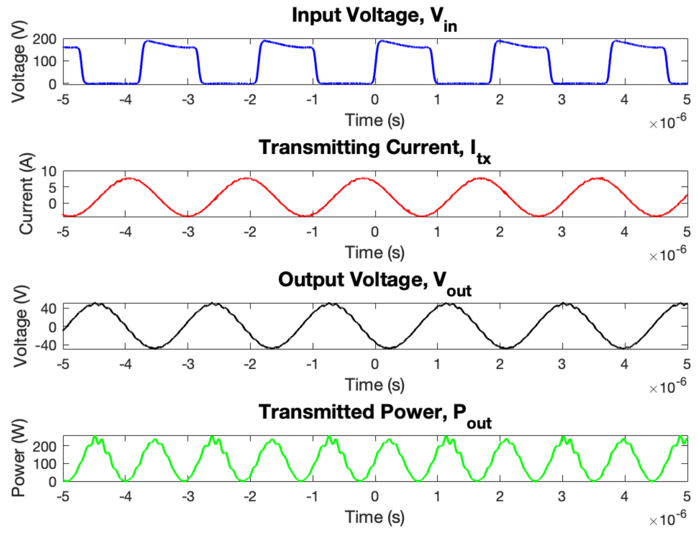
Figure 13 shows the captured waveforms from the experimental verification, and
Figure 14 illustrates the transmitted power as the input voltage is incrementally raised. The SC—WPT achieves an output power of 116.5 W when supplied with an input voltage of 140 V. The output voltage measured across the same load resistance of 10
is 45.38 V, with an energy efficiency of 68.72%.
Within the operational limits, including a constant resonant frequency, coupling coefficient, consistent parameters, and operating within the thermal range, the input voltage of 50 V is used to demonstrate the misalignment and energy efficiency of the SC—WPT.
Figure 15a illustrates the lateral misalignment along the x—axis. The energy efficiency gradually increases as the Rx coil is repositioned laterally away from the Tx coil. The highest energy efficiency achieved is 77.11% at 0.7 m.
Figure 15b shows the experiment conducted to observe the energy efficiency of the SC—WPT under angular misalignment conditions. The recorded data indicate a significant drop in energy efficiency as
is gradually increased. The highest energy efficiency of 73.23% is observed at
, while the lowest energy efficiency of 1.662% occurs when the Rx coil is rotated
about the z—axis.
The energy efficiency reported in this study refers to the end-to-end DC-to-DC efficiency of the WPT system. Specifically, it accounts for the total electrical power measured at the DC output of the rectifier (receiver side) relative to the DC input supplied to the inverter (transmitter side). This includes the losses associated with the inverter, coil coupling (AC–AC), and rectification stages. Measurements are performed using calibrated probes and oscilloscopes to capture RMS values at both the input and output sides, ensuring an accurate representation of the full-system efficiency.
Table 5 summarizes the comparison between simulated and experimental results. The maximum output power shows a minor deviation of −1.27%, with the experimental value measured at 116.5 W and the simulated prediction at 118.0 W. This close match indicates that the simulation accurately captures the power transfer capability of the square coil winding under ideal and controlled conditions. Similarly, the peak energy efficiency yields a deviation of −2.39%, with experimental measurements reaching 68.72%, compared to a simulated maximum of 70.4%. These results confirm that losses introduced by non-idealities in real-world components such as switching inefficiencies, resistive losses in connectors, and measurement tolerances. It is reasonably low and does not substantially impair the overall system performance.
At specific lateral offsets, the system also demonstrates consistency. At 0.6 m, the efficiency deviation is just +0.16%. This reflects a reasonable correlation between predicted and observed performance under spatial misalignment conditions. This is particularly significant in mobile robotics where consistent performance over variable coil alignment is critical for operational robustness.
Finally, a more significant deviation of +16.06% is observed in the self-inductance of the receiver coil. This may result from differences in the construction tolerances, the coil sagging during deployment, or unaccounted-for electromagnetic interactions with nearby metallic structures. The simulation assumes an ideal coil geometry with fixed winding positions, whereas the physical system involves a retractable frame subject to slight deformation, spacing variation, and parasitic coupling effects. These geometric factors can substantially impact inductance, especially in multi-turn, air-core coils. This small difference further supports the mechanical accuracy of the fabricated prototype and indicates that the retractable structure maintains a stable inductive profile during deployment.
6. Discussions
Table 6 presents a comparative analysis of recent WPT systems developed for mobile and embedded applications. The proposed system in this work which is based on a retractable square coil (SC—WPT) delivers 116.5 W at 1 m with 68.72% efficiency. The results represent a balance of power, range, and mechanical reconfigurability. Compared to other systems, it is among the few capable of combining high power delivery and mid-range distance with a deployable coil structure.
Sen et al. (2024) [
35] origami inductor system demonstrates high peak efficiency (83.58%) in a tightly coupled setup but operates at much shorter distances (1–2 cm) and is optimized for compact high-frequency DC-DC converters rather than mobile WPT. Similarly, Stepins et al. (2023) [
36] and Suakaew et al. (2021) [
37] report efficient performance in low-power AGV and warehouse applications. However, these systems operate over shorter transfer distances (up to 16 cm) and do not support geometric reconfiguration.
Ohori et al. (2023) and Yan et al. (2020) [
38] provide moderate to high power levels (20–150 W) with efficiencies ranging from 40% to 60%, but both rely on fixed or impedance-matched driver coils. These configurations offer useful adaptability under load variation or spatial misalignment but lack the deployability and compact storage capabilities needed for mobile robots in constrained environments. Hassan et al. (2024) [
26] report a comparable power level (109.7 W) at 1 m but with significantly lower efficiency (47.14%) and no structural reconfigurability.
The integration of the WPT system with the mechanical structure of a mobile robot imposes strict constraints on the coil’s geometry, size, and deployment mechanism. To meet these constraints, the coil design has to balance electromagnetic performance with mechanical feasibility. The square coil is ultimately selected not only due to its favorable coupling characteristics under aligned conditions but also because of its suitability for implementation within a retractable frame. Unlike more complex or circular geometries, the square shape lends itself naturally to construction using straight, rigid segments, which can be folded and extended through a scissor-linkage mechanism.
This geometry enables a compact and folded configuration during robotic operation and an expanded form during charging. It maximizes the effective coil area without permanently occupying valuable space on the robot. Furthermore, the square design allows for consistent deployment using a minimal number of actuators. This supports system simplicity and reduces energy consumption. This is an important consideration for battery-operated mobile platforms. The modular and linear nature of the scissor mechanism also promotes structural robustness, as each linkage can evenly distribute mechanical loads across the frame during expansion and compression.
In this context, the choice of the square coil represents a deliberate trade-off between optimal electromagnetic field uniformity and mechanical design efficiency. The integration process emphasizes compatibility between the coil’s physical footprint and the robot’s chassis, as well as the reliability of repeated deployment cycles. These combined considerations inform the design of a functional and reconfigurable WPT receiver, suitable for practical implementation in mobile robotic systems.
In summary, these comparisons highlight the unique contribution of the present system. It is the only design among those surveyed that supports both mid-range power delivery (>100 W at 1 m) and mechanical reconfigurability, making it particularly well suited for autonomous robotic applications where compact storage, efficient charging, and adaptive deployment are essential. Its performance demonstrates that structural adaptability does not necessarily come at the expense of efficiency or range, setting a new benchmark for integrated WPT solutions in mobile systems.
7. Conclusions
This paper presents a novel approach to address space and integration challenges in WPT systems for mobile robots by developing a retractable square coil design. The proposed system demonstrates a maximum transmitted power of 116.5 W with an energy efficiency of 68.72% over a 1 m transfer distance. This prototype demonstrates competitive performance when benchmarked against recent WPT systems designed for mobile robots and shows a notable improvements over a previous fixed octagon coil design.
A 5× size compression ratio is successfully implemented through a scissor-linkage mechanism, validating the concept of a reconfigurable WPT receiver suitable for space-constrained robotic platforms. The system achieves higher efficiency while also offering mechanical reconfigurability, minimal actuator complexity, and better integration potential for mobile platforms. The performance and adaptability of the proposed design illustrate its potential as a deployable and efficient alternative to fixed-coil WPT systems, particularly for autonomous robotic platforms where space, mobility, and charging flexibility are critical.
Simulation and experimental results confirm the system’s sensitivity to both lateral and angular misalignments, particularly in angular rotations about the z—axis, where energy efficiency drops significantly. While this highlights a limitation of the current setup, it also opens opportunities for further research. While the reconfigurable coil system’s performance has been validated under free-space conditions in this work, several challenges and opportunities remain to optimize its practical deployment and durability:
The potential for WPT through non-metallic obstacles, such as concrete walls, represents a promising application area. Future work will include the experimental validation of transmission performance across varying obstacle thicknesses and compositions, focusing on power attenuation, alignment sensitivity, and thermal effects.
Another important enhancement is the integration of an automatic coil alignment system to dynamically adjust the receiver coil position relative to the transmitter. This would mitigate spatial misalignments during docking or irregular operating conditions and optimize coupling efficiency. Potential approaches include visual servoing, magnetic field gradient sensing, and low-power beacon-based feedback control.
Further investigation will explore passive magnetic field shaping techniques or flux-guiding structures to enhance power transfer efficiency and spatial tolerance.
Incorporating active alignment strategies, such as adaptive impedance matching or multi-coil arrays, could further improve system robustness to misalignment.
The exploration of alternative coil topologies, including Double-D (DD) or hybrid coil configurations, will be conducted to assess their misalignment tolerance and compatibility with the retractable mechanism.
Additionally, future studies will consider the effect of coil sagging and deformation on inductive properties, aiming to refine the mechanical and electromagnetic co-optimization of retractable WPT systems. Further improvements to the accelerated life testing can be explored in future work, where a more in-depth investigation could be carried out to propose a more robust and feasible retractable design, optimizing the mechanism’s overall performance.


