Abstract
The aim of this study was to assess the maxillary arch asymmetry in paediatric subjects with functional posterior crossbite. Linear widths and depths of maxillary hemi-arches were measured in crossbite patients (29 girls, 14 boys; mean age: 9.49 ± 1.22 years) and in a control group (26 girls, 18 boys; mean age: 9.35 ± 0.70 years) without crossbite. Differences in the linear widths and depths between the two maxillary sides were analysed and compared between groups. Additionally, a 3D superimposition of the mirrored maxillary models was performed for each subject to evaluate dental–alveolar and palatal vault-matching percentages and compare between groups. The Mann–Whitney U test was used for the statistical analysis. The differences in the maxillary hemi-arch linear distances between the two sides of the maxilla were significantly greater in the study group than in the control group (p = 0.000). Matching percentages of the upper arch were lower in the crossbite group (p = 0.000), particularly in the dental–alveolar region of the molars. These findings indicate that maxillary asymmetry in both the transverse and sagittal dimensions is more pronounced in crossbite patients, and the deviations between the two maxillary halves are more evident at the dental–alveolar level and in the molar region.
1. Introduction
A crossbite is defined as an abnormal buccal–lingual relationship of the teeth in which one or more teeth may be abnormally positioned either lingually or buccally [1]. Crossbites can occur at the front (anterior crossbite) or at the sides (posterior crossbite) of the mouth. The most common type of posterior crossbite is unilateral with a functional mandibular deviation to the crossbite side, known as functional posterior crossbite (FPCB). This occurs between 80% and 97% of posterior crossbite cases [2]. A discrepancy between the intercuspation position (ICP) and the centric relation (CR) is evident in a functional crossbite, whereas ICP and CR are usually coincidental in a true unilateral crossbite. A lateral mandibular shift in FPCB results in a mandibular midline deviation towards the crossbite side and often in an asymmetric inter-occlusal sagittal molar relationship. FPCB is often associated with a mild symmetrical bilateral maxillary narrowing [3], which affects posterior occlusion leading to a functional mandibular deviation to the crossbite side during closing. Dental, skeletal, respiratory, and neuromuscular factors can be recognised as possible etiological factors [2,4,5,6], or FPCB may result from oral habits [7].
Treatment of FPCB often involves the removal of occlusal interferences and slow or rapid bilateral maxillary expansion during the deciduous or early mixed dentition stages [5,8,9,10].
However, symmetrical transverse expansion of the maxilla in the mixed dentition, which is the most common treatment [11,12], does not always fully correct midline deviations or the asymmetric sagittal molar relationship in a clinical context. This may be due to an underlying asymmetry in the maxilla or in the mandible [13,14,15], which can be either skeletal or dental [16].
A 3D digital model assessment of children with unilateral posterior crossbite and controls without crossbite found that the surfaces of the two hemi-palatal parts of the vault were symmetric in both treated and untreated patients with unilateral posterior crossbite and in the control group [17]. Conversely, an analysis of transverse maxillary arch form using occlusograms of patients with unilateral functional crossbite revealed different arch morphology, with the crossbite side being either symmetric, contracted, or expanded compared to the non-crossbite side [13]. Notably, an expanded hemi-maxillary arch on the crossbite side is statistically associated with skeletal mandibular asymmetry [13]. Another study, analysing palatal transverse dimensions and performing a 3D evaluation of digital casts, showed that FPCB patients exhibited symmetrical palatal vault narrowing but an asymmetrical narrowing of the alveolar bone [14].
However, the above-mentioned studies analysed either the skeletal or alveolar asymmetry of the maxilla or the dental asymmetry of the maxillary arch but only in the transverse plane.
Since both transverse and sagittal maxillary arch dimensions contribute to dental–alveolar morphology, both should be analysed to evaluate the presence of dental–alveolar asymmetry in FPCB patients.
This study aimed to analyze maxillary arch asymmetry in patients with FPCB. Maxillary arch was split in two halves, linear transverse and sagittal measurements of the two halves of the maxillary arch were taken in patients with FPCB and compared with those of a control group without crossbite.
Additionally, 3D superimpositions of the digital models were performed to compare the asymmetry in the palatal morphology between the two groups.
The null hypothesis states that there are no differences in the grade of asymmetry of the linear measurements of the maxillary arch transverse and sagittal dimensions, as well as the palatal morphology, between the FPCB and the control group.
2. Materials and Methods
2.1. Study Design
This retrospective case-control study was conducted according to the ethical principles of the Declaration of Helsinki. Ethical approval was granted by the local Ethics Committee (ASST Spedali Civili, Comitato Etico di Brescia—approval date: 26 April 2021, protocol 4555). Participants provided written informed consent before enrolling in the study.
2.2. Study Population
The sample size was determined with G*Power software (Heinrich Heine Universität Düsseldorf, Düsseldorf, Germany-version 3.1.9.2). The primary outcome was the difference in hemi-arch molar widths between the two groups. Setting the level of statistical significance at α = 0.05 and statistical power at β = 0.80, considering a clinically significant difference of 0.60 mm in the mean outcome between the groups, and with a standard deviation of 0.99 mm estimated from a pilot study [18] on 10 patients, the required sample size was calculated to be n = 40 per group.
2.3. Target Population
Initially, 92 subjects were included in this study- 46 with FPCB and 46 in a control group (CG) without crossbite.
The children with FPCB were selected from a consecutive patient cohort treated at the Orthodontics Department of the Spedali Civili between 2010 and 2020.
The study group consisted of children with a Class I incisor relationship (lower incisors occlude on or immediately behind the upper incisors’ palatal cingula) [19], presenting with three or more posterior teeth in crossbite, an asymmetric sagittal first molar relationship (Class I on one side and Class II on the other side), and a mandibular midline deviation of 2 mm or more towards the crossbite side at the maximum intercuspal position and not at mouth opening (functional crossbite).
Selected dental casts were in the intertransitional mixed dentition phase [20], characterised by fully erupted permanent incisors and first molars along with the presence of the deciduous canines, and first and second deciduous molars.
The exclusion criteria comprised the following: (1) craniofacial syndromes; (2) transposition, missing maxillary or peg-shaped lateral incisors, tooth agenesis; (3) >2 mm dental crowding assessed by the irregularity index; (4) abnormal tooth shape and size; (5) severe carious lesions.
Age- and sex-matched control group participants were selected from children treated between 2010 and 2020 in the dental clinic of the Spedali Civili using the same inclusion and exclusion criteria, except for the presence of FPCB and related signs. All the controls presented with a Class I incisor relationship without posterior crossbite, an asymmetric molar class relationship, and mandibular midline deviation.
2.4. Dental Cast Analysis
The maxillary plaster casts of subjects with FPCB and in the control group were scanned using the 3D scanner Sinergia Scan (Nobil-Metal, Villafranca d’Asti AT, Italy- version 7.0), which was validated previously [21]. They were then converted into 3D stereolithographic models using specialized software (OrthoAnalyzer™, 3Shape, Holmens Kanal 7, 1060 Copenhagen K, Denmark- version 2018.2.3.0).
Linear measurements and 3D analysis were performed to assess maxillary arch asymmetry.
2.5. Linear Distances
After importing the digital models into OrthoAnalyzer™, the same operator (LG), with 20 years of orthodontic experience, performed the following operations for each patient starting from the models in occlusion (Figure 1a):
- (1)
- Alignment of the upper digital models in the transverse, sagittal, and occlusal directions.
- (2)
- Identification of the occlusal plane and its setting as a reference plane. The occlusal plane of the upper arch was defined using three reference points (Figure 1b,c), as outlined below:
- Numbers 11–21: The most incisal point of the upper central incisors;
- Number 16: The mesio-palatal cusp of the upper first right molar;
- Number 26: The mesio-palatal cusp of the upper first left molar.
- (3)
- Measurement of linear distances on the upper model to assess dento-alveolar asymmetry. These distances were measured in both the transverse and sagittal planes, and the upper midline distance from a reference plane was also evaluated.
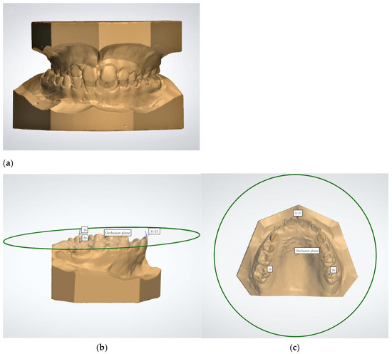
Figure 1.
(a–c). Digital models in occlusion, lateral and occlusal views of the upper digital model with the set occlusal plane. Numbers 11–21: the most incisal point of the upper central incisors; 16, 26: the mesio-palatal cusp of the right and left first molars.
2.6. The Measurements on the Transverse Plane
To analyse the transverse distances of the maxillary arch, a Raphe plane (RP) perpendicular to the occlusal plane was marked on the digital models by means of two reference points located on the median palatal raphe. One reference point (A) was identified as the most distal point of the incisive papilla (Figure 2). The second reference point (B) was placed as the most posterior visible point on the median palatal raphe [22] (Figure 2).
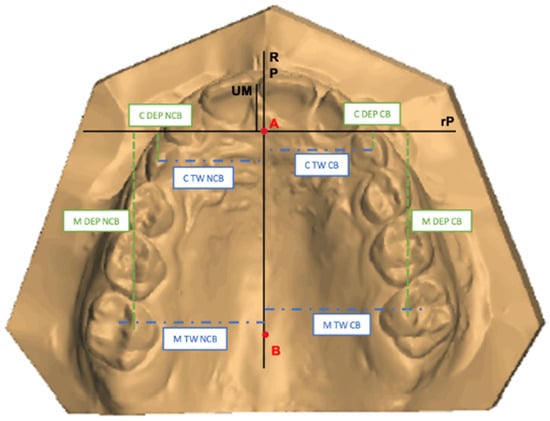
Figure 2.
Maxillary digital model of a patient with FPCB with the representation of Raphe plane, reference plane, and the linear transverse and sagittal distances measured on Crossbite Side (CB) and Non-Crossbite Side (NCB) sides. A: the most distal point of the incisive papilla; B: the most posterior visible point on the median palatal raphe. RP: Raphe plane; rP: reference plane; C TW CB: Canine Width on the Crossbite Side; C TW NCB: Canine Transverse Width on the Non-Crossbite Side; M TW CB: Molar Transverse Width on the Crossbite Side; M TW NCB: Molar Transverse Width on the Non-Crossbite Side; C DEP CB: Canine Depth on the Crossbite Side; C DEP NCB: Canine Depth on the Non-Crossbite Side; M DEP CB: Molar Depth on the Crossbite Side; M DEP NCB: Molar Depth on the Non-Crossbite Side, UM: upper midline.
After identifying the RP, the following measurements were performed (Figure 2):
- Canine Transverse Width (C TW) in mm: The distance between the cusp of the upper deciduous canine and the RP in both quadrants;
- Molar Transverse Width (M TW) in mm: The distance between the mesial fossa of the upper first molar and the RP in both quadrants.
The differences between the measurements in the two quadrants were also calculated and labelled as DIFF C TW and DIFF M TW.
The transverse width discrepancies between the two halves of the maxilla in the study group were then compared with those in the control group.
2.7. The Measurements on the Sagittal Plane
To analyse the maxillary arch depth, the reference plane (rP) was traced on digital casts. This plane was perpendicular to the Raphe plane and passed through the most distal point of the incisive papilla (Figure 2).
After identification of the rP, the following measurements were taken (Figure 2):
- Canine Depth (C DEP) in mm: The distance between the cusp of the upper deciduous canine and the rP in both quadrants;
- Molar Depth (M DEP) in mm: The distance between the mesio-palatal cusp of the upper first molar and the rP in both quadrants.
The differences between the measurements in the two halves of the maxilla were calculated and labelled as DIFF C DEP and DIFF M DEP.
The depth discrepancies between the two halves of the maxilla in the study group were compared with those in the control group.
2.8. Upper Midline Deviation
The upper dental midline was analysed in relation to the Raphe plane. For each model, the distance between the dental upper midline (UM)—defined as the midpoint between the central incisors—and the Raphe plane was measured (UM-RP) (Figure 2). The distances between the UM-RP were then compared between the two groups.
2.9. Three-Dimensional Evaluation
Afterwards, the digital models were exported to a specialized software (Geomagic Control X, 3D Systems, Rock Hill, SC, USA- version 2018.1.1) to assess dento-alveolar and palatal vault asymmetry. This was achieved by superimposing the mirrored models for each patient and performing a 3D analysis of deviations between the two halves of the maxillary arch. The deviations found in the FPCB group were compared with those of the controls.
The workflow for the superimposition—which is a modified version of the method described by Leonardi et al., 2018 [14]—was carried out by the same operator (LG), with 20 years of orthodontic experience, for each subject in this study. The process involved the following five key steps:
- (1)
- Orientation: The occlusal plane was set identifying the same three reference points used in OrthoAnalyzer™. Then, the digital models were aligned so that the occlusal view was parallel to the occlusal plane (Figure 3a).
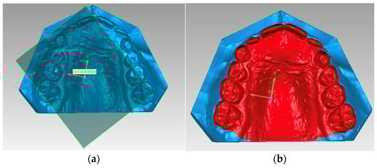
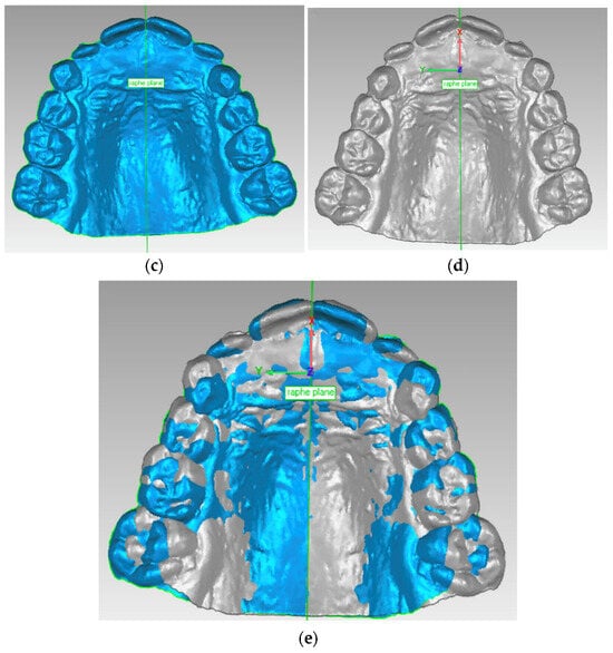 Figure 3. (a–e): (a) Orientation based on the occlusal plan; (b) Segmentation of the digital model; (c) Raphe plane set perpendicular to occlusal plane; (d) Mirrored maxillary model; (e) Best-fit alignment of mirrored models.
 - (2)
- Segmentation: To define the surface of the model to be analysed, a gingival line was drawn along the most apical regions of the buccal dentogingival junction of all maxillary teeth. The posterior limit was delineated from the most posterior point of the right and the left first molars (Figure 3b).
- (3)
- Mirroring: A Raphe plane was set perpendicular to the occlusal plane and the maxillary model was transversely flipped so that the right-side points of the median raphe appeared on the left and vice versa (Figure 3c,d).
- (4)
- Superimposition: The “best-fit alignment” function in the Geomagic Control X was used to superimpose the original maxillary model with the mirrored one. This fine-matching technique uses thousands of reference points and is based on an iterative closest-point algorithm. The precision of the superimposition was set to at least 0.2 mm, and the number of polygons for surface representation was fixed at the maximum of 100.000 (Figure 3e).
- (5)
- Three-Dimensional Analysis: Distances between corresponding points of the original maxillary model and the mirrored version were calculated to generate colour-coded maps (Figure 4). A tolerance range of ±0.25 mm with a height of ±1.5 mm was established. In the colour-coded maps, areas within the tolerance range (indicating matching between the two mirrored 3D casts) are shown in green. Yellow-to-red ranges indicate that the mirrored models are more expanded than the original casts, whereas light blue-to-dark blue ranges indicate that the mirrored model is narrower than the original (Figure 4).
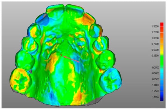 Figure 4. Maxillary model 3D analysis. RGB-coloured scale rod (millimetres) is shown on the right: the scale denotes both positive (red) and negative (blue) height differences. Green signifies the tolerance range.
2.10. Statistical Analysis
2.10.1. Data Collection
The subjects’ data were anonymised by assigning a progressive numerical code, and all measurements were recorded in a Microsoft Excel spreadsheet (Microsoft, Redmond, Washington, DC, USA). The assessor (LG) was blinded to the study and control groups. All the measurements were repeated twice, with a washout period of one month, and the mean values were used for statistical analysis. Intra-examiner reliability was assessed by means of the intraclass correlation coefficient (ICC) and the method error was calculated with Dahlberg’s formula.
2.10.2. Data Analysis
Descriptive statistics were used to examine the demographic features of the FPCB and control groups. Student’s t-test was applied for comparing numerical data (such as age), while the chi-square test was used for categorical variables (such as gender) between the two groups.
The data were quantitative and were reported as medians and interquartile ranges (25th–75th). The normality of the data distribution was assessed with Shapiro–Wilk test, while Levene’s test was used to evaluate variance homogeneity. Since the linear measures and the hemi-palate matchings were not normally distributed, comparisons between the FPCB and the control groups were performed through the Mann–Whitney U test. Statistical analyses were conducted using STATA 17 (StataCorp. College Station, TX, USA) with a significance level set at a p value of ≤ 0.05.
3. Results
3.1. Study Sample and Reliability
Five patients (three boys from the FPCB group and two girls from the control group) were excluded due to unclear visualisation of the posterior palate, which prevented 3D analysis. The final study group consisted of 43 patients (29 girls and 14 boys; mean age ± SD: 9.49 ± 1.22 years), including 23 with right-side crossbite and 20 with left-side crossbite. The control group included 44 subjects (26 girls and 18 boys; mean age ± SD: 9.35 ± 0.70 years). No statistically significant differences were found when comparing the two groups demographically.
3.2. Measurement Reliability
Intraclass correlation coefficient (ICC) values indicated high measurement reliability: 0.95 for C TW, 0.99 for C DEP, 0.98 for both M TW and M DEP, and 0.94 for hemi-palate matchings, reflecting near-perfect accuracy. Measurement error, calculated using Dahlberg’s method, ranged between 0.13 and 0.16 mm for linear measurements and was 1.18% for hemi-palate matchings.
3.3. Case-Control Comparison
Statistically significant differences were found when evaluating the asymmetries in the transverse width and sagittal depth between the crossbite (CB) and non-crossbite (NCB) sides in patients with FPCB, compared to the corresponding right and left sides in the control group. The FPCB group demonstrated notably greater discrepancies in both canine and molar transverse widths (DIFF C TW and DIFF M TW) as well as depths (DIFF C DEP and DIFF M DEP), indicating a more pronounced transverse and sagittal asymmetry of the maxillary arch (Table 1). Additionally, the UM-RP value—reflecting the deviation in the upper dental midline from the mid-sagittal Raphe plane—was significantly higher in the FPCB group (median: 0.20, IQR: 0.00–0.70; p = 0.000) compared to the control group. This finding strengthens the hypothesis that the maxillary arch in patients with FPCB exhibits a greater degree of asymmetry.

Table 1.
Descriptive statistics and statistical comparisons of digital model variables between FPCB and CG.
The percentage of hemi-palatal matching was significantly lower in the FPCB group (median: 37%, IQR: 31–46%) compared to the control group (median: 51%, IQR: 42–59%; p = 0.000) (Table 1), showing the presence of greater transverse and sagittal asymmetry in the maxilla of patients with FPCB. The digital colour-coded 3D models further support this finding. A visibly lower concentration of green—representing areas within the acceptable range of symmetry—is observed in the FPCB group (Figure 5a) compared to controls (Figure 5b). In FPCB patients, 3D deviations are predominantly localised in the dento-alveolar region, particularly in the molar area, while the palatal vault appears less affected. This pattern suggests that the asymmetry is primarily dento-alveolar rather than skeletal in nature, with a greater impact in the posterior maxilla.
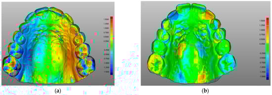
Figure 5.
(a,b): (a) Maxillary model 3D analysis of a patient with FPCB; (b) Maxillary model 3D analysis of a patient in the control group. RGB-coloured scale rod (millimetres) is shown on the right: the top (red) and the bottom (blue) of the scale denote the positive and negative differences in height. Green signifies the tolerance range.
4. Discussion
The digital casts of 43 patients with FPCB and 44 controls were analysed to investigate the asymmetry of the maxillary dento-alveolar and palatal vault regions by measuring transverse and sagittal linear distances and performing superimpositions and 3D analyses.
The findings revealed that the study group exhibited a greater degree of asymmetry between the two halves of the maxillary models in both the transverse and sagittal directions compared to the control group. Moreover, the 3D analysis confirmed that the asymmetry of the maxilla in the patients with FPCB was more pronounced than in the control group. Therefore, the null hypothesis was rejected.
Statistical analysis demonstrated that the differences in canine and molar widths and depths between the two sides of the maxilla were significantly larger in the study group compared with the control group (e.g., DIFF M TW was 1.23 mm in the FPCB group and 0.50 in the CG with p < 0.000). This confirmed that patients in the FPCB group presented greater maxillary arch asymmetry in the transverse and sagittal planes compared to control subjects.
The difference in transverse and sagittal measurements between the two halves of the maxilla in the study group was approximately 1 mm. However, the interquartile range revealed that, clinically, the asymmetry could reach more relevant values. For instance, the difference in the transverse distance of the molars from the midpalatal raphe (DIFF M TW) was 1.23 mm (IQR 0.63–2.14), and the difference in the sagittal position of the canines between the two halves of the maxilla (DIFF C DEP) was 1.00 mm (IQR 0.46–1.43).
Additionally, the upper dental midline showed a deviation from the Raphe plane of 0,20 (IQR 0.00–0.70) in the study group. These findings align with those of Deshayes [23], who identified and described dento-alveolar asymmetries in the maxilla of patients affected by FPCB. Furthermore, these results support the potential role of dento-alveolar asymmetries as contributing factors in the etiology of an asymmetric malocclusion, as already explored by Sanders et al. [24] in Class II subdivision malocclusion.
The result of the 3D analysis supported the hypothesis of greater maxillary arch asymmetry in the study group. The percentage of matching—which was obtained from the superimposition of the mirrored models—was significantly lower in the study group (37%) compared to the control group (51%), with the greatest discrepancies observed at the dento-alveolar level. These findings align with those reported by Leonardi et al. [14], who compared the 3D models of patients affected by FPCB to a control group of patients without FPCB by analysing differences between mirrored casts of the palatal vault. Their study demonstrated a lower percentage of the models in the study group (83.36%) compared to the control group (92.82%), with the most pronounced asymmetries located at the alveolar bone level. The higher matching percentages found by Leonardi et al. [14] compared to the present study may be attributed to the fact that their analysis did not include the teeth in the maxillary section. Conversely, the maxillary arch asymmetry observed in patients with FPCB found in the present study is not supported by the findings of Primoziv et al. [17], who reported a palatal vault correspondence of 91.84% in untreated patients with functional posterior crossbite and children without crossbite. However, they used a tolerance range of −0.5 mm to + 0.5 mm for matching, whereas the present study employed a stricter tolerance range of −0.25 mm to + 0.25 mm.
Furthermore, it is important to emphasise that the maxillary asymmetry highlighted by the 3D analysis is not only due to the difference in transverse linear distances between the two halves of the maxillary arch but also due to the difference in sagittal linear distances between the two halves of the maxillary arch. This was previously found by a study using scanned dental casts, which showed patients with FPCB exhibiting asymmetric rotation and mesial displacement of the upper first molars compared to a control group of Class I non-crossbite subjects [25].
The routine approach of symmetrically expanding the upper arch for patients affected by FPCB is challenged by these results. If an asymmetric arch is clinically verified, this may indicate the need for orthodontic treatment that not only corrects the maxillary palatal vault constriction but simultaneously addresses the dento-alveolar asymmetry.
These transverse and sagittal dental–alveolar asymmetries should be assessed at an early age to ensure proper management during the different phases of the orthodontic treatment.
Previously, some authors [13,26] have emphasised the importance of correcting maxillary arch asymmetry, when it occurs in the transverse plane, with asymmetrical maxillary expansion [26].
If the maxillary arch asymmetry is present in the sagittal plane, it may worsen the asymmetric Class I molar relationship and the midline discrepancy, which are both caused by the mandibular shift. In this case, correction of the mandibular shift in a Class I FPCB patient should be performed alongside correction of the asymmetric sagittal position of the canines and molars, ensuring a correct molar relationship and aligning the upper midline with the palatal raphe. Slavicek [27] and Greene [28] emphasised that during the intertransitional mixed dentition, the positioning and rotation of the first molars, along with the transition from deciduous to permanent anterior teeth, significantly influence mandibular movement patterns and temporomandibular joint (TMJ) adaptations. Thus, establishing a Class I molar relationship during this critical period is essential for guiding proper TMJ and mandibular structural development.
Molar asymmetrical de-rotation and distalisation [25], combined with asymmetric slicing or extraction of deciduous teeth [29,30], may aid in achieving a symmetric molar Class I relationship and correcting upper arch midline deviation.
Failure to correct these dento-alveolar asymmetries can affect permanent occlusion, mandibular growth, and TMJ adaptation [31], potentially leading to more complex orthodontic mechanics or the need for asymmetric extractions at later stages.
Early diagnosis and management of maxillary arch asymmetries could reduce the need for more complicated orthodontic mechanics or asymmetric extractions in later stages.
The 3D evaluation of the maxillary arch can facilitate the early detection of dental–alveolar asymmetries and emphasises their clinical importance in guiding the type of expansion or orthodontic intervention (symmetrical vs. asymmetrical). The use of digital data in early orthodontic screening allows for a more personalised and efficient treatment approach.
When assessing maxillary arch asymmetry using a 3D analysis of dental casts, it is essential to consider tooth position together with the alveolar process and the palatal vault [25]. The strengths of this study lie in its comprehensive evaluation of the dento-alveolar arch and the implementation of a more rigorous tolerance threshold in the three-dimensional analysis.
This study presents certain limitations. First, linear vertical measurements of the maxillary hemi-arches were not analysed as the upper occlusal plane—used as a reference—can be influenced by the vertical positioning of the right and left first molars.
Second, although cases with crowding were excluded, in some instances, dental misalignment exceeded the maximum allowable negative or positive deviations between the two hemi-arches. However, this was primarily observed in the anterior teeth region.
Third, some values exhibited high variability in both the study and control groups, limiting the ability to establish precise comparisons.
5. Conclusions
The study outcomes suggest the following:
- The transverse dimension differences between the two sides of the maxilla may be more pronounced in subjects with functional posterior crossbite (FPCB) compared to the control group (CG);
- Sagittal asymmetries between the two sides of the maxilla appear to be more marked in the FPCB group than in the CG;
- A greater deviation in the upper midline was observed in the study group, which could indicate an asymmetric positioning of the anterior teeth;
- Maxillary arch matching percentages tended to be lower in individuals with FPCB compared to controls.
Future studies could explore the longitudinal progression of dento-alveolar asymmetries, particularly in growing patients, to better understand how such discrepancies evolve over time and potentially influence craniofacial development. In addition, further research is needed to evaluate the effectiveness and stability of asymmetric orthodontic treatments compared to traditional symmetric approaches. Finally, investigating the integration of digital 3D analyses in treatment planning could also provide valuable insights into improving personalised orthodontic care.
Author Contributions
Conceptualisation, I.T. and D.D.; methodology, I.T. and M.L.G.; validation, I.T. and D.D.; formal analysis, M.L.G.; investigation, L.G. and L.L.; resources, M.G.P. and D.D.; data curation, L.G.; writing—original draft preparation, I.T.; writing—review and editing, M.G.P. and D.D.; visualisation, L.G. and L.L.; supervision, I.T. and M.G.P.; project administration, M.G.P. and D.D. All authors have read and agreed to the published version of the manuscript.
Funding
This research received no external funding.
Institutional Review Board Statement
This study was conducted in accordance with the Declaration of Helsinki and approved by the local Ethics Committee (approval date: 26 April 2021, protocol 4555).
Informed Consent Statement
Informed consent was obtained from all subjects involved in this study. Written informed consent was obtained from the patients to publish this paper.
Data Availability Statement
The raw data supporting the conclusions of this article will be made available by the authors on request.
Acknowledgments
The authors would like to thank the orthodontic laboratory, ORTOVIT, in Gorle, for kindly lending the Nobil-Metal Sinergia Scan and the 3Shape Ortho Analyzer computerized software.
Conflicts of Interest
The authors declare that they have no conflicts of interest.
Abbreviations
The following abbreviations are used in this manuscript:
| FPCB | Functional posterior crossbite |
| ICP | Intercuspation position |
| CR | Centric relation |
| CG | Control group |
| RP | Raphe plane |
| C TW | Canine Transverse Width |
| M TW | Molar Transverse Width |
| DIFF C TW | Difference in Canine Transverse Width |
| DIFF M TW | Difference in Molar Transverse Width |
| rP | Reference plane |
| C DEP | Canine depth |
| M DEP | Molar depth |
| DIFF C DEP | Difference in Canine Depth |
| DIFF M DEP | Difference in Molar Depth |
| UM | Upper midline |
| CB | Crossbite side |
| NCB | Non-crossbite side |
| ICC | Intraclass correlation coefficient |
| RGB | Red–green–blue |
| SD | Standard deviation |
| IQR | Interquartile range |
| N | Number |
References
- Proffit, W.R.; Fields, H.W.; Sarver, D.M.; Ackerman, J.L. Contemporary Orthodontics, 5th ed.; Elsevier: St. Louis, MO, USA, 2013. [Google Scholar]
- Kennedy, D.B.; Osepchook, M. Unilateral posterior crossbite with mandibular shift: A review. J. Can. Dent. Assoc. 2005, 71, 569–573. [Google Scholar] [PubMed]
- Wertz, R.A. Skeletal and dental changes accompanying rapid midpalatal suture opening. Am. J. Orthod. 1970, 58, 41–66. [Google Scholar] [CrossRef] [PubMed]
- Choi, S.H.; Kim, Y.J.; Kim, J.; Park, Y.C. Factors associated with functional posterior crossbite in children: A systematic review. Angle. Orthod. 2022, 92, 104–110. [Google Scholar]
- El-Mangoury, N.H.M.Y.; El-Badrawy, H.E. Etiology and early intervention strategies for functional posterior crossbite. Am. J. Orthod. Dentofacial. Orthop. 2022, 162, e569–e577. [Google Scholar]
- Iodice, G.; Danzi, G.; Cimino, R.; Paduano, S.; Michelotti, A. Association between posterior crossbite, skeletal, and muscle asymmetry: A systematic review. Eur. J. Orthod. 2016, 38, 638–651. [Google Scholar] [CrossRef]
- Galán-González, A.F.; Domínguez-Reyes, A.; Cabrera-Domínguez, M.E. Influence of bad oral habits upon the development of posterior crossbite in a preschool population. BMC Oral Health 2023, 23, 1–7. [Google Scholar] [CrossRef]
- Di Carlo, G.; Sfondrini, M.F.; Cacciafesta, V. Early palatal expansion: Clinical effectiveness and 3D evaluation. Prog. Orthod. 2023, 24, 6. [Google Scholar]
- Harrison, J.E.; Ashby, D. Orthodontic treatment for posterior crossbites. Cochrane Database Syst. Rev. 2001, 8, CD000979. [Google Scholar] [CrossRef]
- Kapetanović, A.; Nakaš, E.; Slaj, M. Early treatment of functional posterior crossbite with maxillary expansion: Effectiveness and stability. Eur J Orthod. 2023, 45, 87–93. [Google Scholar]
- Agostino, P.; Ugolini, A.; Silvestrini-Biavati, A.; Harrison, J.E.; Klaus, B.S.L.B. Orthodontic treatment for posterior crossbites. Cochrane Database Syst. Rev. 2021, 2021, CD000979. [Google Scholar] [CrossRef]
- Cozzani, M.; Rosa, M.; Cozzani, P.; Siciliani, G. Deciduous dentition-anchored rapid maxillary expansion in crossbite and non-crossbite mixed dentition patients: Reaction of the permanent first molar. Prog. Orthod. 2003, 4, 15–22. [Google Scholar] [CrossRef] [PubMed]
- Ferro, F.; Spinella, P.; Lama, N. Transverse maxillary arch form and mandibular asymmetry in patients with posterior unilateral crossbite. Am. J. Orthod. Dentofac. Orthop. 2011, 140, 828–838. [Google Scholar] [CrossRef] [PubMed]
- Leonardi, R.; Lo Giudice, A.; Rugeri, M.; Muraglie, S.; Cordasco, G.; Barbato, E. Three-dimensional evaluation on digital casts of maxillary palatal size and morphology in patients with functional posterior crossbite. Eur. J. Orthod. 2018, 40, 556–562. [Google Scholar] [CrossRef] [PubMed]
- Tortarolo, A.; Rotolo, R.; Nucci, L.; Tepedino, M.; Crincoli, V.; Piancino, M.G. Condylar Asymmetry in Children with Unilateral Posterior Crossbite Malocclusion: A Comparative Cross-Sectional Study. Children 2022, 9, 1772. [Google Scholar] [CrossRef]
- Allen, D.; Rebellato, J.; Sheats, R.; Ceron, A.M. Skeletal and dental contributions to posterior crossbites. Angle Orthod. 2003, 73, 515–524. [Google Scholar] [CrossRef]
- Primožič, J.; Baccetti, T.; Franchi, L.; Richmond, S.; Farčnik, F.; Ovsenik, M. Three-dimensional assessment of palatal change in a controlled study of unilateral posterior crossbite correction in the primary dentition. Eur. J. Orthod. 2011, 35, 199–204. [Google Scholar] [CrossRef]
- Gilberti, L. Three-Dimensional Evaluation of the Digital Casts of Maxillary Dental-Alveolar Symmetry in Patients with Unilateral Posterior Functional Crossbite: A Pilot Study; Department of Medical and Surgical Specialties, Radiological Sciences and Public Health, University of Brescia: Brescia, Italy, 2014. [Google Scholar]
- BSI. Glossary of Dental Term (BS4492); British Standards Institute: London, UK, 1983. [Google Scholar]
- Van der Linden, F.P.G.M.; Duterloo, H. The Development of the Human Dentition; An Atlas. Harper and Row Publishers: Hagerstown, MA, USA, 1976; pp. 145–195. [Google Scholar]
- Pagano, S.; Moretti, M.; Marsili, R.; Ricci, A.; Barraco, G.; Cianetti, S. Evaluation of the Accuracy of Four Digital Methods by Linear and Volumetric Analysis of Dental Impressions. Materials 2019, 12, 1958. [Google Scholar] [CrossRef]
- Moyers, R.E. Handbook of Orthodontics; Year Book Medical Publishers Inc.: Chicago, IL, USA, 1988. [Google Scholar]
- Deshayes, M.J. Cranial asymmetries and their dento-facial and occlusal effects. L’Orthodontie Française 2006, 77, 87–99. [Google Scholar] [CrossRef]
- Sanders, D.A.; Rigali, P.H.; Neace, W.P.; Uribe, F.; Nanda, R. Skeletal and dental asymmetries in Class II subdivision malocclusions using cone-beam computed tomography. Am. J. Orthod. Dentofac. Orthop. 2010, 138, 542.e1–542.e20. [Google Scholar] [CrossRef]
- Tonni, I.; Iannazzi, A.; Piancino, M.G.; Costantinides, F.; Dalessandri, D.; Paganelli, C. Asymmetric molars’ mesial rotation and mesialization in unilateral functional posterior crossbite and implications for interceptive treatment in the mixed dentition. Eur. J. Orthod. 2016, 39, 433–439. [Google Scholar] [CrossRef]
- Farronato, G.; Giannini, L.; Galbiati, G.; Maspero, C. Comparison of the dental and skeletal effects of two different rapid palatal expansion appliances for the correction of the maxillary asymmetric transverse discrepancies. Minerva Stomatol. 2012, 61, 45–55. [Google Scholar] [PubMed]
- Slavicek, R. Relationship between occlusion and temporomandibular disorders: Implications for the gnathologist. Am. J. Orthod. Dentofac. Orthop. 2011, 139, 10–16. [Google Scholar] [CrossRef] [PubMed]
- Greene, C.S. Relationship between occlusion and temporomandibular disorders: Implications for the orthodontist. Am. J. Orthod. Dentofac. Orthop. 2011, 139, 11–15. [Google Scholar] [CrossRef]
- Christensen, R.T.; Fields, H.W.; Christensen, J.R.; Beck, F.M.; Casamassimo, P.S.; McTigue, D.J. The Effects of Primary Canine Loss on Permanent Lower Dental Midline Stability. Pediatr. Dent. 2018, 40, 279–284. [Google Scholar] [PubMed]
- Rosa, M. Sequential slicing of deciduous teeth. J. Clin. Orthod. 2001, 35, 696–701. [Google Scholar]
- Sakamoto, T.; Iwase, Y.; Ueki, K.; Marukawa, K.; Nakagawa, K.; Yamamoto, E. Mandibular asymmetry: Relationship with occlusion, craniofacial morphology, and masticatory muscle activity. Am. J. Orthod. Dentofacial. Orthop. 2008, 134, 793–800. [Google Scholar]
Disclaimer/Publisher’s Note: The statements, opinions and data contained in all publications are solely those of the individual author(s) and contributor(s) and not of MDPI and/or the editor(s). MDPI and/or the editor(s) disclaim responsibility for any injury to people or property resulting from any ideas, methods, instructions or products referred to in the content. |
© 2025 by the authors. Licensee MDPI, Basel, Switzerland. This article is an open access article distributed under the terms and conditions of the Creative Commons Attribution (CC BY) license (https://creativecommons.org/licenses/by/4.0/).