Review

Chloride-Induced Corrosion Effects on the Structural Performance of Concrete with Rebar and Fibres: A Review

1
Civil and Environmental Engineering Department, Universitat Politècnica de Catalunya (UPC), Jordi Girona 1–3, 08034 Barcelona, Spain
2
International Centre for Numerical Methods in Engineering, Centro Internacional de Métodos Numéricos en la Ingeniería (CIMNE), Paseo General Martínez Campos, 41, 9°, 28010 Madrid, Spain
*
Author to whom correspondence should be addressed.
Appl. Sci. 2025, 15(12), 6457; https://doi.org/10.3390/app15126457
Submission received: 6 May 2025 / Revised: 30 May 2025 / Accepted: 5 June 2025 / Published: 8 June 2025
(This article belongs to the Special Issue Fiber-Reinforced Concrete: Recent Progress and Future Directions)

Abstract

Chloride-induced corrosion is a major contributor in the degradation of standardised steel-based products (e.g., rebars and fibres) commonly used for reinforcing concrete structures. Since cracked reinforced concrete elements are determined to be more susceptible to corrosion on the one hand, and fibres are effective in arresting crack growth and improving the post-cracking mechanical behaviour on the other hand, the use of fibres emerges as a promising strategy to enhance durability. This review is focused on the degradation of the load-bearing capacity, caused by chloride corrosion, in concrete elements reinforced with fibres and conventional rebar. Based on the recorded values of ultimate loads and the corresponding deflections in the reviewed studies, a lower decrease in the load-bearing capacity and less severe degradation of ductility were observed in elements where fibres (either steel or macro-synthetic) were used in combination with rebar compared with elements where only rebar was used. Furthermore, the recorded values of corrosion potential (Ecorr), corrosion current density (icorr) and gravimetric measurements indicated lower corrosion damage, delayed corrosion initiation and a prolonged propagation phase of corrosion. However, due to many differences in the methodology among the reviewed studies, the optimal fibre type or quantity cannot be identified unless more studies are performed.

1. Introduction

Reinforced concrete (RC) became the predominant building material in construction during the 20th century and remains widely used today. RC buildings are estimated to account for approximately 60% of all buildings constructed in this period in Europe [1]. Furthermore, an analysis of the European Union’s (EU) building stock reveals that concrete is utilised in over 95% of floor structures [2]. Its dominance is similarly evident in infrastructure: according to Žnidarič et al. [3], 67% of all bridges within the EU are made from RC. Similarly, in the United States (US), RC bridges constitute 65% of the total bridge inventory [4].
Many of these structures are currently exceeding their design service life of 50 years and are exhibiting signs of degradation. In the US alone, 15% of the bridges were observed to be structurally deficient due to corrosion [4], and according to Polder et al. [5], even modern structures are not immune to degradation. Moreover, Tilly et al. [6] and Visser et al. [7] raised concerns about the efficiency of current repair strategies, reporting that as many as 50% of repaired structures in the European region require additional interventions within just 10 years.
In 2016, the US-based National Association of Corrosion Engineers (NACE) reported on the global economic impact of corrosion. Expressed as a percentage of gross domestic product (GDP), the annual cost was estimated at 2.7% in the US, 3.8% in the European region and up to 5.0% in the Middle East, with a global average of 3.4% [8]. A similar figure was reported by Koch et al. [4] for the US (3.1% of GDP per annum), identifying the annual direct cost related to infrastructure corrosion at USD 22.6 billion, with indirect costs (e.g., due to closures, delays and increased transportation times) potentially reaching USD 226 billion. Although these figures encompass all types of corrosion, chloride-induced corrosion likely constitutes a significant share, since it is recognised as one of the primary causes of RC structure degradation [9,10,11].
The potentially high cost of chloride-induced corrosion may be further supported by demographic trends: approximately 25% of the world’s population live close to the coast (i.e., less than 50 km from the sea), and this population is growing faster than inland population [12]. This drives coastal development and, consequently, the number of structures exposed to marine environments. For example, airborne sea salts were detected as far as 50–80 km inland [13]. Furthermore, in many of the coastal zones, the use of de-icing salts is common throughout winter months, and the risk of corrosion is further increased.
Given the significant costs associated with corrosion and the growing need for more efficient use of resources, as well as sustainable infrastructure solutions, this study aims to investigate alternative approaches to the current construction practices. In this regard, one potential alternative is the transition from traditional RC to fibre-reinforced concrete (FRC) or rebar-reinforced–fibre-reinforced concrete (RR-FRC) as structural materials, since the addition of fibres improves post-cracking performance. Furthermore, FRC offers advantages by partly (or completely) reducing the need for rebar, thereby lowering labour costs and construction time. Its adoption as a structural material is already supported by standards like the new Eurocode 2 [14] or ACI 544 [15]. Reflecting this institutional endorsement, the global FRC market is projected to grow at a compound annual growth rate of 6.77% [16].
This study seeks to provide an overview of the current state of knowledge regarding the structural performance of chloride-corroded RR-FRC elements, with an emphasis on the degradation of load-bearing capacity, since the simultaneous sustained loads and chloride exposure may lead to structural failures, resulting in loss of life and significant material damage [17,18]. The analysis is limited to normal-strength concrete, as its use is still more prevalent than high-performance concrete (HPC) or ultra-high-performance concrete (UHPC). The review focuses exclusively on steel and macro-synthetic fibres, as these are the most commonly used fibres for reinforcing concrete [19].

2. FRC Under Chloride Ingress

Chloride-induced corrosion of rebar is a complex electrochemical process that results in a reduction in the rebar cross-section, consequently increasing internal stress in the rebar and adversely affecting its mechanical behaviour. For this process to occur, sufficient oxygen and chloride concentrations [10] need to be reached at the level of rebar in concrete, and a closed electrical circuit must be formed.
Due to the abundance of oxygen in both the atmosphere and the ocean, usually, the build-up of chlorides dictates when the corrosion process is initiated [20]. Once the chloride concentration reaches the critical threshold (Ccrit, expressed as a percentage of binder mass) [21,22], the protective layer on the rebar surface—formed in the highly alkaline environment of fresh concrete—is damaged, and chloride-induced corrosion is initiated.
In the ensuing electrochemical reaction, the rebar itself acts as a mixed electrode [23], where anodes (localised areas where chloride ions break down the protective passive layer) and cathodes (intact passive regions) coexist. The steel bar serves as the metallic pathway, connecting these anodic and cathodic sites electrically. Meanwhile, the concrete pore solution functions as the electrolyte, enabling the movement of ions to complete the electrical circuit. As a consequence, two simultaneous electrochemical reactions occur: an anodic reaction, where the iron in the steel rebar is oxidised (resulting in rebar degradation), and a cathodic reaction, where the oxygen is being reduced, which allows for the corrosion process to be sustained.
The movement of chlorides through the concrete matrix (and subsequent build-up until Ccrit) may be caused by the pressure gradient (permeation), concentration gradient (diffusion), capillary forces (absorption) or any combination of these factors, which exist between the interior and the exterior of the concrete element [10]. Therefore, the design codes (i.e., ACI 318 [24] or Eurocode 2 [25]) focus on preventing chlorides from reaching Ccrit as a means of achieving adequate durability of the structures. This may be achieved by strictly limiting the presence of free chlorides in component materials or by slowing down their ingress. Namely, porosity is directly proportional to permeability and may be reduced by lowering the water–cement (w/c) or water–binder (w/b) ratios, whereas the diffusion effects can be mitigated by increasing the concrete cover depth (c) to rebar.
Cracks are also recognised as another significant factor in chloride ingress and subsequent rebar corrosion. There is ongoing debate regarding the precise impact and significance of certain crack characteristics, such as the crack widths (w), the number and spacing of cracks (crack frequency) or crack orientation relative to the rebar. Locally, cracks act as preferential pathways for chloride ingress, connect internal pores [26] and may diminish the protective role of concrete cover. Since cracks are unavoidable in RC (even under service loads), their impact is specifically addressed by limiting the permissible crack widths (wmax) in design codes [24,25].

2.1. Behaviour of FRC Under Tensile Stress

The beneficial effects of fibres on post-cracking concrete performance are well established after decades of research. Once the concrete’s tensile strength is exceeded, further crack opening is influenced not only by the concrete’s tensile strength, as in plain concrete (PC), but also by the bond between fibres and the matrix (pull-out) and the fibres’ own tensile strength [27]. Depending on the characteristics of the constituent materials, such as fibre volume fraction (Vf), bond strength or fibre orientation, FRC elements might exhibit strain-softening (where the deformations localise in one crack) or strain-hardening (where multiple cracking occurs before the peak load is reached) behaviour [28]. Relative to PC, FRC elements are found to be more ductile, with narrower and more closely spaced cracks [29,30,31], implying that the ingress of chlorides through FRC might be slower than in the case of PC.
On this account, extensive research has been conducted to investigate the impact of various fibres on the behaviour of fibre-reinforced concrete (FRC) under chloride ingress. Steel (S) fibres have been studied the most, with macro-synthetic (MS) fibres, such as polyethylene (PE), polypropylene (PP) and polyvinyl alcohol (PVA), also receiving significant attention. Furthermore, the performance of hybrid-fibre-reinforced concrete (HyFRC), which combines multiple fibre types (Hy), was also investigated. In this study, the following naming convention is used: XFRC refers to instances where rebar is not used, with “X” representing the previously defined fibre material and “FRC” denoting fibre-reinforced concrete; in instances where both rebar and fibres are used, the prefix RR is added, i.e., RR-XFRC.

2.2. Impact of Fibres on Chloride Ingress in Concrete

Several authors, including Berrocal et al. [32], Paul et al. [33], Marcos-Meson et al. [34], Gopu and Joseph [35], Ma et al. [36], have performed extensive literature reviews on the durability aspects of different types of FRC. Focusing exclusively on findings related to chloride-induced corrosion and incorporating insights from more recent studies, a summary table of key conclusions from previous research is provided below (Table 1). The table serves as a basis for evaluating the performance of RR-FRC elements in the following chapter. Unless otherwise noted, the crack width values (w) refer to widths to which the elements were pre-cracked.
Fibres themselves may also be susceptible to corrosion depending on their composition. On the one hand, steel fibres (SF) have been found to be prone to corrosion according to Hwang et al. [37]; however, the study’s authors observed that their corrosion resistance was higher compared to rebar and attributed this enhanced resistance to the presence of mill scale on the fibre surface. Mangat [38] offered an alternative explanation, suggesting that the increased resistance to chlorides of SF might result from their production process. Gao et al. [39] identified a linear relationship between the duration of SF exposure to sodium chloride (NaCl) and the reduction in fibre diameter. They also observed that the corrosion rate of SF is affected by pH levels, with higher pH values (above 12) resulting in a very slow corrosion rate. This finding underscored that the corrosion of SF is governed by the same fundamental mechanism as the corrosion of rebar. Masmoudi and Bouaziz [40] found that coating SF in triethanolamine (TEA) is an efficient method to increase their resistance to corrosion. Wang et al. [41] observed an increase in the bond strength of corroded SF on account of the increased surface roughness of corroded fibres.
On the other hand, Woishnis and Ebnesajjad [42] compiled a comprehensive report on the chemical resistance of thermoplastic materials. Based on it, polyethylene and polypropylene as materials have excellent resistance to seawater and NaCl exposure at various temperatures. This implies that polypropylene fibres (PPF) and polyethylene fibres (PEF) themselves are immune to chloride attack. This claim is further supported by the results of a review by Alberti et al. [19] on the use of polyolefin (PPF, PEF) in the construction industry.
Table 1. Experimental setups and concrete properties considered in the reviewed campaigns regarding FRC.
Paperw/bDuration
[d]
MaterialVf
[%]
NaCl
[%]
w
[mm]
Conclusion
[43]0.3091MSFRC, SFRC, HyFRC 1SF: 0.25–1.00,
PPF: 0.15–0.45
10.00.00
-
SF reduce electrical resistivity;
-
SF and PPF reduce water absorption with the increase in Vf;
-
PPF increase porosity;
-
Addition of silica fume to the mixes increases electrical resistivity.
[44]0.31-PC, SFRCSF: 0.7610.00.00
-
Similar water absorption of PC and SFRC;
-
SF reduce electrical resistivity of concrete by 63%.
[45]0.3291PC, MSFRCPPF: 0.50–1.5010.00.00
-
PPF decrease chloride ion migration.
[46]0.62-PC, MSFRCPPF: 0.05–0.153.00.00
-
PPF decrease water absorption, chloride penetration and porosity. The effects are better in specimens with higher Vf.
[47]0.60120PC, MSFRC, SFRCPPF: 0.40–0.80,
S: 0.40–0.80
100.00.00
-
PPF and SF reduce water absorption and chloride ion penetration depth, with PPF being more effective.
[48]0.4328PC, MSFRC, SFRC, HyFRCPPF: 0.40–0.60, S: 0.65–0.85-0.00
-
Water absorption is increased in SFRC and decreased in PPFRC;
-
SFRC have a higher sorptivity coefficient;
-
Chloride penetration is increased in SFRC and HyFRC;
-
Increase in Vf of PPF helps mitigate negative aspects of SF in HyFRC.
[49]0.32-PC, MSFRCPPF: 0.05–0.44-0.00
-
PPFRC has higher resistance to chloride ion penetration, lower water penetration and sorptivity coefficient.
[50]0.5990PC, HyFRCPPF: 0.12, S: 0.523.0,
3.5 and
10.0
0.00
-
HyFRC has a lower sorptivity coefficient;
-
Chloride ion diffusion is lower in HyFRC.
[51]0.41-PC, MSFRCPPF: 0.10–0.503.00.00
-
PPF increase permeability with respect to PPFRC with silica fume.
[52]0.78, 0.48, 0.36210SFRCSF: 0.503.50.00
-
w/c ratio below 0.5 is sufficient to prevent fibre corrosion.
[53]0.60-PC, SFRC, MSFRCSF: 0.50–1.25, PPF: 0.50–1.25-0.00
-
All types of FRC have lower chloride ion permeability than PC.
[54]0.30180PC, SFRCSF: 1.503.50.00
-
Higher initial stress led to faster corrosion initiation in SFRC elements.
[55]0.60-PC, MSFRCPPF: 0.10–0.50-0.00
-
Permeability of PPFRC is lower compared to PC;
-
Permeability of both PPFRC and PC depends on the compressive stress in the specimen, and it is more pronounced in the case of PC than PPFRC.
[56]0.42-PC, MSFRCPPF: 0.06–0.09-0.00
-
Increase in chloride diffusion coefficient with an increase in fibre content.
[57]0.48-PC, MSFRCPPF: 0.05–0.22-0.00
-
PPFRC elements have lower permeability than PC;
-
PPFRC elements with Vf higher than 0.11% exhibit higher electrical resistivity;
-
PPFRC caused delay in starting the degradation process.
[58]0.40180PC, SFRCSF: 0.503.5–7.00.00–0.30
-
No substantial damage in uncracked specimens exposed to chlorides;
-
No substantial corrosion of steel fibres due to chlorides;
-
Increase in toughness of elements with smaller cracks (0.15 mm) compared to uncracked specimens;
-
Decrease in toughness of elements with wider cracks (0.30 mm);
-
Corrosion damage of fibres had negative (but secondary) effect on the residual flexural strength of cracked SFRC.
[59]0.50238SFRCSF: 0.325.00.50–0.60
-
Long-term behaviour and residual strength were similar in exposed and unexposed specimens.
[60]0.43-PC, MSFRCPPF: 0.44–0.66-0.00–0.27
-
Cracked PPFRC has higher tortuosity, and the crack surface roughens;
-
Permeability of cracked PC is higher than that of PPFRC.
[61]0.30 and 0.40330PC, MSFRCPPF: 0.75–1.0010.00.02–0.28
-
Total amount of chlorides on the crack fracture surface is higher in the case of PPFRC than PC.
[62]0.4390PC, SFRCSF: 1.003.50.50 and 1.00
-
Chlorides completely penetrated cracks up to 1.00 mm after 90 days of exposure in SFRC;
-
Post-cracking behaviour of SFRC was not affected by chloride penetration.
[9]0.60365SFRCSF: 0.503.50.50
-
Light fibre corrosion but without spalling of concrete cover and reduction in cross-section;
-
Increase in the residual flexural strength of SFRC beams.
[63]0.45-PC, SFRCSF: 0.50 and 1.00-0.00–0.50
-
SFRC has lower permeability than PC. An increase in fibre quantity decreases permeability;
-
For cracks less than 0.10 mm, fibres are not effective in reducing permeability.
[64]0.43-PC, SFRC, MSFRC, HyFRCSF: 0.23, PP: 1.963.00.00
-
Water absorption of PPFRC was higher relative to PC. SFRC and HyFRC performed similarly to PC;
-
Chloride permeability was lowest in PC, followed by HyFRC, SFRC and PPFRC.
[65]0.3530PC, MSFRCPVAF: 0.30–1.505.00.00
-
Decrease in porosity with an increase in fibre content;
-
Increase in fibre content up to 1.2% results in decreased permeability.
1 Hybrid-fibre-reinforced concrete
The results from studies reviewed in Table 1 predominantly point to increased water tightness, lower permeability and lower chloride penetration in FRC elements compared to PC, with benefits correlating with an increase in the fibre content, regardless of fibre type. On account of this, superior durability of FRC materials might be expected due to the prolonged time necessary for chlorides to build up to Ccrit at the level of rebar. However, in a smaller number of studies, the opposite was observed, namely superior performance of PC compared to FRC, thus pointing to the fact that more research is necessary. The main drawback of using fibres was determined in the case of SF due to increased electrical conductivity (lower electrical resistance of SFRC).

3. RR-FRC Under Chloride Ingress

Steel bars are used as concrete reinforcement for both serviceability (SLS) and ultimate limit states (ULS). These are placed in positions where the tensile stresses are expected to occur and with a certain concrete cover, whose magnitude depends on the environmental conditions, design service life and other factors related to the concrete matrix. Fibres, on the other hand, are randomly distributed within the volume and, with adequate geometry and amount, provide concrete with post-cracking resistance to control crack propagation. The combination of both reinforcement types is gaining practical interest in elements (i.e., tunnel linings, flat slabs, precast panels, sewerage pipes and others) for which the maximum crack width is challenging to fulfil with steel bars only due to design requirements or in instances where the risk of congestion of rebar is high. In this context, the hybridisation of reinforcements leads to both technical and economic advantages.
A summary of the key experimental parameters from the reviewed campaigns on RR-FRC is provided in Table 2 below. They include exposure duration (d), fibre length (lf), fibre diameter (df), concrete cover (c), compressive strength (fc) and other previously defined parameters (i.e., w/b, w). The outcomes of the experimental campaigns are presented in the following subsections. Since some of the campaigns examined multiple aspects of corrosion, such as initiation or reduction in load-bearing capacity, detailed descriptions of the campaign are provided only in the subchapters where one of the aspects is first introduced. This approach maintains clarity and eliminates redundant information.

3.1. Corrosion Initiation and Corrosion Propagation in RR-FRC

3.1.1. Effects of Cracks on Corrosion Initiation and Propagation

Berrocal et al. [80] investigated the structural performance of elements exposed to chlorides under various loading and cracking conditions. Wetting and drying cycles were used to accelerate corrosion. Four different loading conditions were considered: (1) uncracked (and non-loaded) specimens, (2) cracked but unloaded specimens, (3) cracked cyclically loaded and unloaded specimens and (4) cracked specimens under sustained loads. Specimens were pre-cracked using a three-point bending test (3PBT), and the same method was used to load specimens to failure after exposure. In Figure 1, the corrosion initiation time based on measurements of corrosion potential (Ecorr) and the rebar weight loss determined by corrosion current density (icorr) are plotted for different concrete types (summarised in Table 2). The influence of cracking conditions is clear (Figure 1), as uncracked elements consistently remained passive for over 30 weeks, whereas cracked elements with w between 0.06 and 0.10 mm experienced nearly instantaneous corrosion initiation.
Nguyen et al. [81] investigated non-loaded and loaded (in pure axial tension) RC and RR-HyFRC elements. An axial tensile load of 53 kN was used to pre-crack specimens (resulting in a tensile stress of 265 MPa in the reinforcement, which is below the threshold value for SLS given in EC2 [25]). The resulting maximal crack widths from axial loads equalled 0.42 mm for RC and 0.22 mm for RR-HyFRC. The effect of fibres on the crack widths can be clearly seen in Figure 2. In ascending order, the time of corrosion initiation was observed after 35 days (loaded RC), 35 days (loaded RR-HyFRC), 301–401 days (non-loaded RC) and 511–681 days (non-loaded RR-HyFRC). In the propagation phase, the same trend was observed, with higher values of icorr in RC than in RR-HyFRC. This study also used accelerated corrosion with wet/dry cycles (2 weeks per cycle) for 912 days, similar to studies by Berrocal et al. [79,80].
In the campaign by Blunt et al. [83], the elements were cyclically loaded in 4PBT (five cycles) up to 42 kN to simulate SLS conditions while maintaining the reinforcement in the elastic range. This resulted in cracks opening in RC elements, whereas RR-HyFRC remained uncracked. Electrochemical measurements indicated that the corrosion process began in RC elements within the first week of exposure, whereas corrosion initiation in RR-HyFRC was only observed after six weeks. The average loss of reinforcement mass due to corrosion was 0.132 g/cm2 for RC and 0.039 g/cm2 for RR-HyFRC elements. In Figure 3, higher degradation of rebar in the case of RC may be observed. This correlates with the percentage of reinforcement surface area covered by corrosion products, averaging 93% for RC and 26% for RR-HyFRC.
In the study by Jen et al. [84], a methodology similar to the one in [83] was used (five loading cycles up to 32 kN in 4PBT were used to pre-crack specimens). After one year, the chloride solution was allowed to evaporate, and corrosion monitoring was continued in dry conditions. Corrosion initiation was fastest in pre-cracked RC specimens (one week), followed by uncracked RC specimens (five weeks). For the first 45 weeks of exposure, no active corrosion process was detected in either uncracked or cracked RR-HyFRC elements. An active corrosion process in the top bars of RR-HyFRC specimens was only detected in the second year of the campaign. In RC elements, cracks formed due to active corrosion, whereas RR-HyFRC remained uncracked. In cracked RC elements, previously induced cracks grew in size and depth, allowing the chloride solution to reach the bottom bar (Figure 4) and initiate the corrosion process. The highest measured value of icorr was recorded for the cracked RC element, amounting to 21.95 μA/cm2 (bottom bar) and 6.05 μA/cm2 (top bar). In the uncracked RC element, the bottom bar remained in a passive state, whereas the icorr for the top bar was 2.80 μA/cm2. For the RR-HyFRC elements, similar values of icorr were observed for the top bars: 0.43 μA/cm2 for the undamaged elements and 0.40 μA/cm2 for the pre-cracked elements. The bottom bars of both RR-HyFRC elements remained in a passive state.
Özyrt et al. [70] investigated the chloride diffusivity and corrosion initiation of uncracked and pre-cracked RR-SFRC specimens exposed to wetting and drying cycles in a solution containing dissolved chlorides. The study considered two values of w/c and two values of c. Elements were pre-cracked using a three-point bending test (3PBT). Pre-cracked elements were simultaneously exposed to sustained flexural loads and chloride ingress. The authors observed the negative effect that cracks have on chloride-induced corrosion of rebar, since, in all cases, corrosion was almost instantaneous in cracked specimens regardless of the fibres, w/c or concrete cover. Delayed corrosion initiation in uncracked elements was observed for the lower w/c ratio (no corrosion after 560 days of exposure) compared to 70–140 days in the case of a higher w/c ratio. Increased cover depth was found to be only effective in the case of uncracked specimens. Fibres were found to enhance performance under corrosion (resulting in a lower chloride content) of cracked RR-SFRC specimens with a lower w/c ratio of 0.45, whereas in other cases, their effect was inconclusive.
Michel et al. [77] specifically focused on the relationship between damage at the steel–concrete interface and the initiation of chloride-induced corrosion. Beam elements were pre-cracked in 3PBT and instrumented rebar (with sensors placed ±10, ±30 and ±70 mm from the main transverse crack) to monitor Ecorr and icorr. The authors observed a good correlation between crack widths and interfacial damage with the extent of chloride-induced corrosion over the bar length. The authors reported delayed corrosion initiation in RR-SFRC specimens with Vf of 0.5% (36 h), whereas in RC and in RR-SFRC specimens with Vf of 1.0%, corrosion initiation was observed after 24 h.

3.1.2. Effects of Loading Conditions on Corrosion Initiation and Propagation

Berrocal et al. [80] determined that loading conditions had a more pronounced effect on corrosion initiation time compared to crack widths. Corrosion initiation occurred earliest in cyclically loaded specimens, followed by those under sustained loads, and lastly, in cracked but unloaded specimens. The authors attributed this to damage in the interfacial zone at the steel–concrete interface. Considering corrosion level (η)—calculated as the difference between initial weight and weight after corrosion, divided by the initial weight—as the criterion for assessment of performance in the propagation phase, similar conclusion as for the initiation phase may be reached.
Sappakittipakorn and Banthia [85] simulated the tidal zone by applying cyclical wetting and drying cycles. Two different loading levels were applied to induce cracks with 15 kN (resulting in cracks of 0.25–0.30 mm) and 30 kN (resulting in cracks of 0.60–0.80 mm). In the case of non-loaded specimens, corrosion initiation was observed after 27 weeks in RC, followed by RR-PPFRC (41 and 47 weeks for Vf of 0.1% and 0.3%, respectively). The same trend was observed in the case of specimens loaded to 15 kN: corrosion was initiated first in RC (3 weeks), then in RR-PPFRC (8 and 13 weeks for Vf of 0.1% and 0.3%, respectively). In specimens loaded to 30 kN, corrosion initiation was detected in all specimens within the first week of exposure.

3.1.3. Other Parameters Influencing Corrosion Initiation and Propagation

Deterioration of tunnel lining segments in chloride-rich environments was studied by Feng et al. [74], focusing on subsea shield tunnels of the Xiamen metro line 2 (Figure 5). The experimental program was divided in three stages: (1) loading with a 250 mm eccentric force of 130 kN; (2) application of direct current for 20 days to accelerate the corrosion of steel bar reinforcement; and (3) loading until failure. The authors found that the increase in Vf delayed the depassivation of steel bars, as indicated by measurements of corrosion potential (Ecorr). Corrosion was first detected in RC elements after 17 h, followed by RR-SFRC (0.5%) after 28 h, and finally, in RR-SFRC (1.0%) after 35 h.
Raczkiewicz et al. [76] used electrochemical polarisation (galvanostatic pulse) to investigate the corrosion of rebar in a chloride-rich environment and freeze–thaw cycles (100 cycles with temperature variation between −18 °C and +18 °C). Specimens were partially submerged in NaCl solution, which allowed the authors to differentiate between a corrosion process where chlorides penetrated directly from the liquid solution (submerged part) and a corrosion process where chlorides reached reinforcement by capillary action and salt fog (floating part). In the submerged parts of the specimens, measurements of corrosion current density (icorr) showed the highest corrosion rate in the case of RC specimens (3.42 μA/cm2). Relative to RC, the values of icorr were observed to decrease in RR-SFRC as the fibre quantity increased. The same trend was observed in the case of the floating parts.
In another study, Raczkiewicz [77] used a similar methodology as in [76] but without exposing specimens to freeze–thaw cycles. For the submerged parts of RC specimens, average values of Ecorr and icorr of −234 mV and 4.61 μA/cm2 were measured, respectively, with similar values observed in RR-PPFRC, indicating a moderate value of corrosion activity. In contrast, low corrosion activity was observed in the floating parts.
Roque et al. [87] produced a report for the Florida Department of Transportation investigating the durability of RC and RR-FRC elements (and their counterparts without rebar). Two different concrete mixes were considered: concrete class II with a w/c ratio of 0.44 and concrete class V with a w/c ratio of 0.37. Pre-cracking was performed in 3PBT. Electrochemical measurements on RC and RR-FRC were performed in accordance with ASTM G 109 [90]. The corrosion of steel bars in RR-FRC elements was tested under the cyclical wetting and drying conditions. Uncracked PC and uncracked and pre-cracked FRC elements were subjected to environmental exposure conditions characteristic of Florida for 27 months. Three different environmental exposure conditions were considered: exposure to lime water, exposure to salt water (5% Cl) and exposure to swamp water (pH 4.5). In the case of exposure to salt water, after 21 months, the concentration of chlorides was increased from 5% to 7%. For exposure to lime and salt water, both immersion and wetting and drying cycles were considered. Exposure to swamp water was considered only in an immersed state. After the end of exposure, surface degradation due to the corrosion process was evident in all concrete types. Measurements of Ecorr were taken for 617 days for all RC and RR-FRC beams. During this period, no corrosion initiation was detected in any specimens made from concrete class V. The shortest corrosion initiation time was reported for RR-SFRC (137 days), followed by RC (190 days), RR-PPFRC (315 days) and RR-PVAFRC (609 days). The study concluded that the best performance under the considered environmental and exposure conditions was observed in PPFRC elements, followed by SFRC and then PVAFRC elements.
Chen et al. [66] performed numerical simulations to investigate the impact of fibres on the service life of concrete structures in a case study of a bridge edge beam exposed to de-icing salts in Sweden. Two different reinforcement layouts were considered per concrete type. On the one hand, this was done in order to consider the improved post-cracking behaviour of the fibres and, on the other hand, in order to investigate the impact of reinforcement detailing (spacing and bar diameter) on the cracking process and subsequent chloride-induced corrosion. The diffusion of chloride solution through uncracked concrete was modelled on Fick’s second law of diffusion, whereas corrosion initiation in the cracked regions was modelled on the work by Leung and Hou [91]. The study used the DIANA 10.3 [92] finite element analysis software to model corrosion-induced cracking. The authors observed a correlation between w and the time required to initiate corrosion (same initiation time in uncracked regions and shorter initiation for wider cracks in all scenarios). Assuming the same corrosion rate in the propagation phase and the loss of load-bearing strength of 15% as a criterion when the structure cannot be used anymore, the authors concluded that the service life of the beam is increased by 58% to 94% in RR-SFRC (Vf = 0.5%) and by 104% to 154% in RR-SFRC (Vf = 1.0%) compared to the RC reference beams.
Mihashi et al. [82] applied electrical potential (3 V) to accelerate chloride-induced corrosion. Corrosion-induced cracks first appeared in RC elements after 27 weeks, followed by cracks in RR-PEFRC after 36 weeks, whereas no corrosion-induced cracks were observed in RR-HyFRC. After exposure, rebar was extracted, and the loss of mass and corroded area (expressed as corroded surface area divided by the total surface area of the bar) were measured. Rebar in the RC specimen was observed to be fully corroded, whereas for RR-PEFRC, the corroded area equalled 65.4%; for RR-HyFRC, it was only 11.8%. In descending order, the rebar mass loss was 69.9 g (RC), 20.0 g (RR-PEFRC) and only 1.0 g (RR-HyFRC).
Flores Nicolás et al. [89] investigated the effects of recycled-polyethylene fibres (RPEF) on the chloride corrosion initiation and propagation. In this study, four different RR-RPEFRC were compared to the reference RC specimens. The authors observed corrosion initiation on the first day for all concrete types. Over the duration of the experiment, the values of icorr showed a decreasing trend in the case of RC (ultimately indicating negligible corrosion rate), whereas specimens with fibres showed a high-to-very-high corrosion rate, with more severe corrosion in instances where long fibres were used. The authors attributed this to the random orientation of fibres in the concrete matrix and to the recycled-polyethylene fibres being susceptible to water absorption, thus potentially increasing the overall ingress of chlorides.

3.2. Effects on Load-Bearing Capacity of RR-FRC

A study by Hou et al. [67] investigated the structural performance of beams simultaneously exposed to chloride ingress and sustained loads in a four-point bending test (4PBT) configuration. Specimens were subjected to 72 days of wetting and drying cycles, after which a direct impressed current was imposed to accelerate corrosion until the target corrosion level (expressed as a percentage of lost mass of reinforcement, η) was achieved (5%, 10% and 15%). Sustained loads corresponded to the fraction of the yield load (Fy) of the uncorroded reference beam. Values of 10%, 20%, 30%, 40% and 50% of Py were investigated. At the end of the exposure period, specimens were subjected to 4PBT until failure. Based on the results obtained (Figure 6), the authors observed a correlation between the level of sustained load to which the beams were subjected during exposure and the recorded value of load-bearing capacity (Fmax). Furthermore, it was observed that both the yield and ultimate loads decreased by a similar percentage, with a reduction in the ductility of the corroded specimens compared to those uncorroded.
Leporace-Guimil et al. [68] used drying and wetting cycles to compare the structural performance of tension ties. Specimens were pre-cracked in pure axial tension and subjected to a sustained axial load of 300 MPa. The authors observed corrosion only in the cracked region of all specimens. The extracted rebar was subjected to axial tensile loads until failure. The loss of tensile capacity of the rebar was comparable between RC and RR-SFRC elements. The reduction in the ultimate strain in bars extracted from RC specimens was larger (26%) compared to the bars extracted from RR-SFRC (22%).
In another study stemming from the same experimental campaign, Leporace-Guimil et al. [69] characterised the pitting corrosion of steel bars. After exposure, steel bars were extracted from tension ties, and their diameters were measured. The average loss of bar diameter due to corrosion was 6.2% and 5.3% for RC and RR-SFRC, respectively. The extracted bars were loaded in uniaxial tension until failure, and the yield load (Fy), ultimate load (Fu) and ultimate strain (εu) were recorded. The results showed a greater scatter in the results of ultimate strain than that in the case of yield or ultimate load, indicating that this parameter is more affected by the corrosion process.
Bafghi et al. [71] investigated chloride-induced corrosion of specimens exposed to different environmental conditions (specimens were kept in fresh water and the atmospheric and tidal zones of the Oman Sea). Uncracked and pre-cracked elements in 4PBT in an unloaded state were considered. Specimens were loaded until failure in bending tests after 28, 90 and 180 days of exposure. In the tidal exposure conditions, the authors observed losses of load-bearing capacity of cracked RC elements of 22% (90 days) and 31% (180 days). In the case of RR-SFRC elements, the load-bearing capacity of cracked elements in the tidal zone increased by 5% (90 days) and 16% (180 days). A similar trend was observed for cracked RC and RR-SFRC elements in the atmospheric conditions of the tidal zone and laboratory conditions. For uncracked specimens, the reduction in load-bearing capacity in the tidal zone of RC specimens was 15% (90 days) and 18% (180 days). The reduction in load-bearing capacity of uncracked RR-SFRC specimens in the tidal zone was 14% (90 days) and 22% (180 days). However, despite the higher reduction in the load-bearing strength of uncracked RR-SFRC compared to RC at 180 days, the load-bearing strength of RR-SFRC was still higher than that of RC in relative terms.
Roshan and Glalenhovi [72] investigated the effects of recycled-tyre-steel fibres (RTSF) and virgin-steel fibres on the chloride-induced corrosion of rebar. The study considered uncorroded beams and beams exposed to accelerated corrosion via direct impressed current (700 mA) to achieve the target corrosion level. Four corrosion levels were considered in the study: η = 0%, 2%, 7% and 10%. Figure 7 shows the recorded values of Fy, Fu, displacement at yield (Δy) and ultimate displacement (Δu) during loading in 3PBT until failure. All concrete types showed signs of degradation of the load-bearing capacity with the increase in corrosion level. Relative to the uncorroded specimen, the loss was highest in the case of RR-SFRC (16%), followed by RR-RTSFRC (11%), whereas RR-HyFRC even showed a slight increase in Fu (2%). A similar trend was observed for loads corresponding to yield and ultimate deflection.
Masmoudi and Bouziz [40] investigated the effects of corrosion inhibitors on structural performance. In one scenario, beams were exposed to a 5.1% NaCl solution, whereas in another scenario, TEA was added to the NaCl solution. The increase in ultimate load in RR-SFRC specimens, particularly with the addition of TEA, emphasises the potential of combining SF with chemical inhibitors to enhance the durability and structural performance of concrete exposed to aggressive chloride environments. In this context, for the same load level (45 kN), the crack widths of RR-SFRC elements were 56% (without the addition of TEA) and 70% (with the addition of TEA) lower than in the case of RC. Furthermore, both types of RR-SFRC had a 17% higher ultimate load compared to the RC element.
Mohamed and Sultan [73] used direct current (13 V) to accelerate chloride-induced corrosion and to investigate bond strength and the loss of load-bearing capacity of the corroded specimens. Three corrosion levels were considered: 0% (uncorroded, reference specimens) η = 6%, 10% and 16%. It was observed that the time required to achieve the target corrosion level was higher for RR-SFRC specimens compared to RC beams by 44%, 54% and 61% for corrosion levels of 6%, 10% and 16%, respectively. In 4PBT, RR-SFRC beams exhibited superior performance compared to RC beams.
Pham et al. [75] used a constant direct current (1 A for 24 days) to accelerate chloride-induced corrosion. At the end of the exposure period, all elements were subjected to 4PBT until failure, and values of the applied load and corresponding deflection were recorded. The results showed that the corroded beams exhibited a 28.7% lower maximum load compared to those uncorroded (Figure 8), implying a clear effect of the degradation of rebar on the structural performance. Both corroded RR-SFRC elements failed due to concrete crushing with reinforcement yielding, which the authors attributed to the presence of fibres and their contribution to the enhanced ductility of concrete elements. The average loss of mass in the corroded specimens was 6.2%, 16.4% and 24.1% for reinforcement in compression, tension and stirrups, respectively, indicating the effects of crack orientation and stress state in the element on the corrosion of rebar.
In another study stemming from the same experimental campaign as in [80], Berrocal et al. [79] investigated structural performance in terms of the load-bearing capacity. In absolute terms, the load capacity of corroded RR-FRC beams was determined to be higher than in the case of RC (Figure 9). Corroded RR-SFRC exhibited a similar loss of rotational capacity as RC, whereas slight improvements were observed for RR-PVAFRC and RR-HyFRC. The loss of reinforcement mass was higher in elements with wider cracks and in cyclically loaded specimens compared to specimens under sustained loads.
In the campaign led by Blunt et al. [83], apart from the impact on the initiation and propagation, the authors observed a difference in the degradation of load-bearing resistance. For RC elements, this value was determined to be 3%, whereas for RR-HyFRC, it was 9%; however, in absolute terms, the load-bearing capacity of corroded RR-HyFRC was 28% higher than that of corroded RC (Figure 10).
Jen et al. [84] observed the impact of corrosion on the load-bearing performance of concrete elements. The flexural stiffness in corroded RC specimens was found to be 33% lower than that in uncorroded reference specimens, and the load corresponding to the opening of flexural cracks in corroded RC elements was 35% lower than in uncorroded beams (Figure 11). In contrast, in corroded RR-HyFRC elements, the load at which flexural cracks opened and flexural stiffness remained similar to the reference specimens.
Maalej et al. [86] investigated the effectiveness of using ductile-fibre-reinforced cementitious composite (DFRCC) to partially substitute PC to enhance the durability and structural performance of concrete beams. The investigation was performed on two series of beams identical in all aspects, except for the partial substitution of PC in the tensile zone with DFRCC in the second series, thus labelled RR-HyFRC. An impressed direct current of 8 V was used to accelerate corrosion. The loss of load-bearing capacity (in 4PBT) relative to the reference (uncorroded) specimens was 13% and 8% for RC and RR-HyFRC, respectively. In absolute terms, corroded RR-HyFRC beams had an 18% higher Fu and a 22% higher Fy load compared to corroded RC beams. A higher loss of reinforcement mass in the corroded specimens was observed in RC (10.1%) than in RR-HyFRC elements (8.3%). By using Faraday’s law to calculate the loss of mass due to corrosion, the study determined that RR-HyFRC elements would require 70% more time to achieve the same amount of corrosion damage as RC elements.
Feng et al. [74] observed a change in the failure mode from ductile to brittle in the case of corroded RC elements. However, in all the remaining specimens, including corroded RR-SFRC, the failure mode remained ductile. The loss of load-bearing capacity decreased with the increase in Vf, with the highest observed loss of 18.5% in RC elements, followed by 16.9% and 13.7% in RR-SFRC (0.5%) and RR-SFRC (1.0%), respectively.
Vo et al. [89] used impressed current (constant current density of 250 μA/cm2) to obtain a corrosion of rebar equal to η = 5% in RC and three different types of RR-SFRC. The load-bearing capacity was assessed using 4PBT. The results demonstrated a clear relationship between fibre content and the extent of load-bearing capacity degradation. Higher fibre content mitigated the severity of degradation, with corroded specimens containing a fibre volume fraction Vf = 1.5%, achieving the same load-bearing capacity as uncorroded reference specimens with the same fibre content. Additionally, the fibres enhanced the ductility of corroded RR-SFRC beams compared to corroded RC beams, with specimens containing Vf = 1.5% exhibiting 50% greater ultimate deflection than RC beams.

4. Discussion

In this study, a literature review was conducted on the impact of fibres on durability and, given their intrinsic connection, the deterioration of the load-bearing capacity of rebar in RR-FRC elements. In this regard, many of the still unresolved issues related to the degradation of RC elements are found to be present in the case of RR-FRC elements but with added complexity originating from the presence of fibres. Quantifying the effects of fibres through direct comparison of experimental findings was found to be challenging due to the substantial variations in key parameters influencing chloride ingress (e.g., concrete cover, water-to-binder ratio, exposure duration, concentration of chlorides in the solution) and the effects of fibres on mechanical performance (e.g., crack widths, fibre quantity, fibre material type) across different experimental campaigns.
This is further complicated by the different loading conditions. Namely, cracks produced via pure axial tension exhibit distinct characteristics compared to those originating from flexural loading. Axial tension cracks propagate uniformly through the entire cross-section RC, forming parallel edges due to the even stress distribution. In contrast, flexural cracks develop a V-shaped geometry as they initiate at the tension face and taper towards the neutral axis, which limits their propagation depth. In this context, the results from campaigns employing flexural loads as a pre-cracking method or sustained loads are more representative of most structures, as pure axial tension is seldom observed in RC elements. Nevertheless, findings from campaigns utilising pure axial tension remain valuable for advancing knowledge in this field, as the stress field in pure axial tension, locally, near the rebar in tension, may resemble that of flexural loading.
It is important to note that several of the reviewed studies used some of the techniques to accelerate corrosion. Namely, chloride-induced rebar corrosion is inherently slow, and it often takes years for its effects to manifest themselves, which makes accelerated methods appealing for obtaining results within a shorter timeframe. In this regard, the use of wetting and drying cycles is more representative of natural corrosion, as it allows for progressively increasing the concentration of chlorides in the solution after each cycle; however, the downside is that it is slower than the use of direct current (DC) to facilitate corrosion.
DC methods can vary depending on whether the potential (U) or current (I) is applied to the element, with each offering distinct advantages and drawbacks (i.e., fixed U is easier to apply and allows for the variation in I with changes in the resistance (R), which is more representative of natural corrosion, whereas fixed I allows for precise corrosion level to be achieved, thus allowing for the reduction in variables in the experimental program). However, if the applied voltage is higher than 1.3 V, water electrolysis occurs [93], leading to the formation of oxygen and hydrogen gases, which have been shown to cause damage at the steel–concrete interface [94], which itself is recognised as one of the important parameters regarding chloride-induced corrosion [95]. In the case of controlling accelerated corrosion by the value of the current, the resulting corrosion current density often results in values that are significantly higher (>10.00 μA/cm2) [96] than the values typically observed in tests with natural corrosion (from 0.10 μA/cm2 to 10.00 μA/cm2) [97,98].
Furthermore, in the case of DC-accelerated corrosion, the whole bar usually acts as an anode, whereas in natural corrosion (or in wetting/drying cycles), parts of the rebar act both as anodes and cathodes. This is in line with the conclusions of Poursaee and Hansson [99], who observed that DC-accelerated chloride-induced corrosion is generally more uniform, impacting the entire surface of the rebar, whereas natural corrosion is typically more localised, particularly in RC. Additionally, they argued that DC-accelerated corrosion produces corrosion products that may differ chemically from those formed during natural corrosion. Moreover, in their literature review regarding different methods of accelerating chloride-induced corrosion, Feng et al. [96] reached a similar conclusion to Poursaee and Hansson [99], arguing that high corrosion current densities may result in more unstable corrosion products with smaller volume than in the case of natural corrosion. Since the lateral pressure exerted by corrosion products directly influences corrosion-induced crack formation (which exposes more of the rebar area to corrosive agents and affects corrosion evolution), the use of DC complicates the evaluation of performance between RC and RR-FRC elements, since fibres alter the damage progression dynamics.
Furthermore, fibres influence both the state of the interfacial transition zone (ITZ) by mitigating damage through a more even distribution of internal stresses and the cracking pattern by promoting greater uniformity, which in turn leads to more uniform corrosion damage. This intricate interaction, where both DC (if water electrolysis occurs) and fibres affect the ITZ and corrosion patterns, complicates comparisons between RC and RR-FRC and makes it challenging to quantify the contribution of fibres when using DC to accelerate corrosion in RR-FRC elements.
In this regard, the application of natural corrosion, or wetting and drying cycles to accelerate corrosion, reduces the complexity and the need to decouple the effects of DC from those of fibres and may therefore lead to more representative results. Moreover, as proposed by Wong et al. [95], the use of multiple techniques, rather than a single one, to study the state of ITZ, especially when DC techniques are used to accelerate corrosion, might help in better understanding the role of ITZ, the effects of using DC, and ultimately, the interplay between fibres and DC.
In the context of this study, all of the reviewed campaigns [73,82,86] where controlled voltage was used to accelerate corrosion applied values above the threshold of 1.3 V, ranging between 3 V and 13 V. Similarly, in studies where controlled current was used [67,72,74,75,89], the resulting current density was above 10 μA/cm2, ranging between 200 μA/cm2 and 1300 μA/cm2. However, it is important to note that the use of accelerated corrosion (both DC and wetting and drying cycles) and natural corrosion exposure in studies still demonstrates consistent trends. Namely, lower degradation of the load-bearing capacity is observed in RR-FRC compared to RC, regardless of the methodology used.

5. Conclusions and Future Research Needs

This study performed a first-ever review of structural performance in terms of the load-bearing capacity of concrete elements exposed to chloride ingress, where fibres and rebar were used in combination as reinforcement. The analysis is limited to normal-strength concrete and steel and macro-synthetic fibres. In the review, significant differences in the methodology and in the parameters that govern chloride ingress were observed. Therefore, a quantitative assessment of the structural performance of RR-FRC under chloride ingress remains challenging. However, an assessment in qualitative terms can be made. The most important conclusions are as follows:
  • Based on the electrochemical measurements of corrosion potential (Ecorr) or corrosion current density (icorr), corrosion initiation was prolonged in RR-FRC elements relative to RC ones. Furthermore, the evolution of Ecorr, icorr, over time and the gravimetric loss of rebar mass after exposure imply a better performance of RR-FRC in the propagation phase.
  • Corrosion of RR-FRC elements is governed by the same mechanisms as corrosion in RC, and as such, similar strategies may be used to mitigate it (related to the mix design, porosity, impermeability, etc.).
  • Based on the recorded ultimate and yield loads (and their corresponding deflections), in general, the degradation of load-bearing capacity (relative to uncorroded elements) was lower in RR-FRC than in RC elements. In a smaller number of instances, where degradation of RC was lower than that of RR-FRC relative to their reference counterparts, corroded RR-FRC still outperformed corroded RC in absolute terms.
  • Fibres prove effective in preserving the ductile failure mechanism in flexure in corroding RR-FRC elements, whereas corroded RC elements tend to fail abruptly, changing the failure mechanism from ductile to brittle. Furthermore, a comparison of ultimate deflection (or deformation) indicates that corroded RR-FRC elements exhibit greater overall ductility than RC.
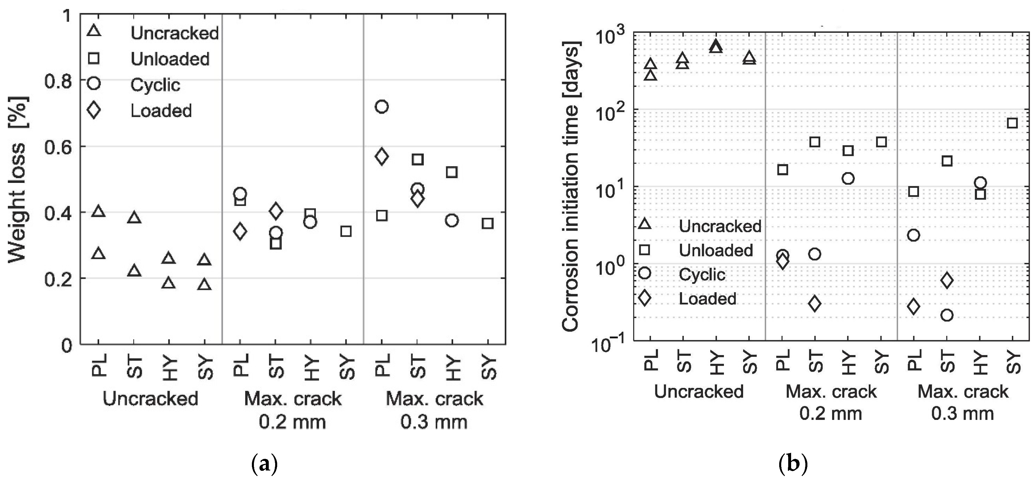
  • The negative effects of cracking on durability (corrosion initiation and propagation) persist for the RR-FRC elements, but their effects are mitigated by the presence of fibres. However, different campaigns reported vastly different corrosion initiation times, even for the same value of crack width.
  • More than crack widths themselves, the loading conditions seem to have a more dominant effect on the performance of RR-FRC under chloride ingress, both on the corrosion initiation and propagation, and consequently, the level of degradation of load-bearing capacity. There is a strong correlation between damage at the steel–concrete interface and degradation of structural performance. Namely, cyclically loaded elements were found to exhibit the highest degradation of load-bearing capacity (even if they were left non-loaded afterwards), followed by elements under static sustained loads, and finally, by undamaged (non-loaded) elements. In this regard, the use of fibres may be especially important, as they mitigate the level of damage at the ITZ.
  • There is no sufficient evidence to claim the superiority of one fibre type (or one RR-FRC type) over others.
  • Due to the potential interference effects of DC usage to accelerate corrosion and fibres on the state of the ITZ, a direct comparison between RC and different types of RR-FRC might be complicated if a DC with high intensity is used.
Based on the reviewed literature and the conclusions drawn by the author, in descending order of importance, the level of knowledge in this field could be further advanced by performing experimental campaigns without the use of DC-accelerated corrosion techniques, as previously discussed. Moreover, expanding the number of studies that analyse the state of the ITZ could help shed more light on the role of ITZ in chloride-induced corrosion. Therefore, if previously divergent threshold crack width values could be unified by linking them to specific ITZ characteristics, this would have the potential to fundamentally redefine crack widths as manifestations of underlying mechanisms rather than primary drivers. Furthermore, the majority of the reviewed studies were performed on small-scale specimens; therefore, a campaign where experiments are performed on large-scale elements (with higher span-to-depth ratio—L/d) may yield cracking patterns that are more representative of the real structures and consequently better capture the effects of chloride-induced corrosion on the degradation of load-bearing capacity.
Ultimately, it is paramount to keep parameters that have an impact on chloride ingress (e.g., w/c) consistent between the different concrete types investigated within the same campaign to allow for adequate comparison and quantification of the effects of fibres on the durability and load-bearing capacity of corroding RR-FRC elements.

Author Contributions

Conceptualisation, P.B. and B.L.-G.; investigation, P.B.; writing—original draft preparation, P.B.; writing—review and editing, B.L.-G., C.A. and N.T.; supervision, A.d.l.F.; funding acquisition, A.d.l.F. All authors have read and agreed to the published version of the manuscript.

Funding

This research was supported by the Master Builders Solutions GmbH, Germany, the Ministry of Science and Investigation (Ministerio de Ciencia, Innovación y Universidades) the State Research Agency (Agencia Estatal de Investigación) of the Kingdom of Spain. Project reference: PID2019-108978RB-C32; grant reference: PRE2020-095457. Support was provided by project Hormigones Reforzados con Macrofibras Sintéticas para Aplicaciones Estructurales en condiciones de altas temperaturas (HEAT), project reference: PID2023-149321OB-C32.

Data Availability Statement

The data presented in this study are available on request from the corresponding author.

Conflicts of Interest

The funders had no role in the design of the study; in the collection, analyses or interpretation of data; in the writing of the manuscript; or in the decision to publish the results.

Abbreviations

The following abbreviations are used in this manuscript:
DCDirect current
EUEuropean Union
FRCFibre-reinforced concrete
GDPGross domestic product
HPCHigh-performance concrete
HyFRCHybrid-fibre-reinforced concrete
ITZInterfacial zone
MSMacro-synthetic
MSFRCMacro-synthetic-fibre-reinforced concrete
NACENational Association of Corrosion Engineers
NaClSodium chloride
PCPlain concrete
PEPolyethylene
PEFPolyethylene fibres
PPPolypropylene
PPFPolypropylene fibres
PVAPolyvinyl alcohol
PVAFPolyvinyl alcohol fibre
RCReinforced concrete
RR-HyFRCRebar-reinforced–hybrid-fibre-reinforced concrete
RR-FRCRebar-reinforced–fibre-reinforced concrete
RR-PERCRebar-reinforced–polyethylene-fibre-reinforced concrete
RR-PPFRCRebar-reinforced–polypropylene-fibre-reinforced concrete
RR-PVAFRCRebar-reinforced–polyvinyl-alcohol fibre-reinforced concrete
RR-RTSFRCRebar-reinforced–recycled-tyre-steel-fibre-reinforced concrete
RR-SFRCRebar-reinforced–steel fibre-reinforced concrete
RPEFRecycled-polyethylene fibre
RTSFRecycled-tyre-steel fibre
SSteel
SFSteel fibre
SFRCSteel-fibre-reinforced concrete
SLSServiceability limit state
TEATriethanolamine
UHPCUltra-high-performance concrete
ULSUltimate limit state
USUnited States
3PBTThree-point bending test
4PBTFour-point bending test

References

  1. Landolfo, R.; Formisano, A.; Di Lorenzo, G.; Di Filippo, A. Classification of european building stock in technological and typological classes. J. Build. Eng. 2022, 45, 103482. [Google Scholar] [CrossRef]
  2. Callegher, C.Z.; Grazieschi, G.; Wilczynski, E.; Oberegger, U.F.; Pezzutto, S. Assessment of Building Materials in the European Residential Building Stock: An Analysis at EU27 Level. Sustainability 2023, 15, 8840. [Google Scholar] [CrossRef]
  3. Žnidarič, A.; Pakrashi, V.; O’Brien, E.; O’Connor, A. A review of road structure data in six European countries. Proc. Inst. Civ. Eng. Urban Des. Plan. 2011, 164, 225–232. [Google Scholar] [CrossRef]
  4. Koch, G.H.; Brongers, M.P.H.; Thompson, N.G.; Virmani, Y.P.; Payer, J.H. Corrosion Costs and Preventive Strategies in the United States; United States Federal Highway Administration: Washington, DC, USA, 2001.
  5. Polder, R.; Pan, Y.; Courage, W.; Peelen, W.H.A. Preliminary study of life cycle cost of preventive measures and repair options for corrosion in concrete infrastructure. Heron 2016, 61, 1–13. [Google Scholar]
  6. Tilly, G.P.; Jacobs, J. Concrete Repairs: Observations on Performance in Service and Current Practice; BRE Electronic Publications: Watford, UK, 2007. [Google Scholar]
  7. Visser, J.H.M.; van Zon, Q. Performance and service life of repairs of concrete structures in The Netherlands. In Proceedings of the 3rd International Conference on Concrete Repair, Rehabilitation and Retrofitting, ICCRRR, Cape Town, South Africa, 3–5 September 2012. [Google Scholar]
  8. Bowman, E.; Thompson, N.; Gl, D.; Moghissi, O.; Gould, M.; Payer, J. International Measures of Prevention, Application, and Economics of Corrosion Technologies Study; NACE Internationa: Houston, TX, USA, 2016. [Google Scholar]
  9. Granju, J.L.; Balouch, S.U. Corrosion of steel fibre reinforced concrete from the cracks. Cem. Concr. Res. 2005, 35, 572–577. [Google Scholar] [CrossRef]
  10. Bertolini, L.; Elsener, B.; Pedeferri, P.; Redaelli, E.; Polder, R. Corrosion of Steel in Concrete; Wiley-VCH: Weinheim, Germany, 2010. [Google Scholar]
  11. Khan, M.U.; Ahmad, S.; Al-Gahtani, H.J. Chloride-Induced Corrosion of Steel in Concrete: An Overview on Chloride Diffusion and Prediction of Corrosion Initiation Time. Int. J. Corros. 2017, 2017, 5819202. [Google Scholar] [CrossRef]
  12. Cosby, A.G.; Lebakula, V.; Smith, C.N.; Wanik, D.W.; Bergene, K.; Rose, A.N.; Swanson, D.; Bloom, D.E. Accelerating growth of human coastal populations at the global and continent levels: 2000–2018. Sci. Rep. 2024, 14, 22489. [Google Scholar] [CrossRef] [PubMed]
  13. Slamova, K.; Schill, C.; Wiesmeier, S.; Köhl, M.; Glaser, R. Mapping atmospheric corrosion in coastal regions: Methods and results. J. Photonics Energy 2012, 2, 022003. [Google Scholar] [CrossRef]
  14. EN 1992-1-1:2003; Eurocode 2—Design of Concrete Structures—Part 1-1: General Rules and Rules for Buildings, Bridges and Civil Engineering Structures. European Committee for Standardization: Brussels, Belgium, 2023.
  15. American Concrete Institute. Guide for Specifying, Proportioning, Mixing, Placing, and Finishing Steel Fiber-Reinforced Concrete; American Concrete Institute: Farmington Hills, MI, USA, 2010. [Google Scholar]
  16. Mordor Intelligence. Fiber Reinforced Concrete Market Size & Share Analysis—Growth Trends & Forecasts up to 2030. Available online: https://www.mordorintelligence.com/industry-reports/fiber-reinforced-concrete-frc-market (accessed on 1 April 2025).
  17. Siemes, A.J.M.; Edvardsen, C. Duracrete Service Life Design For Concrete Structures. In Proceedings of the 8th International Conference on Durability of Building Materials and Components, Vancouver, BC, Canada, 30 May–3 June 1999. [Google Scholar]
  18. Morgese, M.; Ansari, F.; Domaneschi, M.; Cimellaro, G.P. Post-collapse analysis of Morandi’s Polcevera viaduct in Genoa Italy. J. Civ. Struct. Health Monit. 2020, 10, 69–85. [Google Scholar] [CrossRef]
  19. Alberti, M.G.; Enfedaque, A.; Gálvez, J.C.; Picazo, A. Recent advances in structural fibre-reinforced concrete focused on polyolefin-based macro-synthetic fibres. Mater. Constr. 2020, 70, e206. [Google Scholar] [CrossRef]
  20. Kanavaris, F.; Coelho, M.; Ferreira, N.; Azenha, M.; Andrade, C. A review on the effects of cracking and crack width on corrosion of reinforcement in concrete. Struct. Concr. 2023, 24, 7272–7294. [Google Scholar] [CrossRef]
  21. Angst, U.; Elsener, B.; Larsen, C.K.; Vennesland, Ø. Critical chloride content in reinforced concrete—A review. Cem. Concr. Res. 2009, 39, 1122–1138. [Google Scholar] [CrossRef]
  22. Ann, K.Y.; Song, H.W. Chloride threshold level for corrosion of steel in concrete. Corros. Sci. 2007, 49, 4113–4133. [Google Scholar] [CrossRef]
  23. Ahmad, S. Reinforcement corrosion in concrete structures, its monitoring and service life prediction—A review. Cem. Concr. Compos. 2003, 25, 459–471. [Google Scholar] [CrossRef]
  24. American Concrete Institute. Building Code Requirements for Structural Concrete (ACI 318M-08) and Commentary; American Concrete Institute: Farmington Hills, MI, USA, 2008. [Google Scholar]
  25. EN 1992-1-1; Eurocode 2: Design of Concrete Structures—Part 1-1: General Rules and Rules for Buildings. European Committee for Standardization: Brussels, Belgium, 2004.
  26. Wang, K.; Jansen, D.C.; Shah, S.P.; Karr, A.F. Permeability study of cracked concrete. Cem. Concr. Res. 1997, 27, 381–393. [Google Scholar] [CrossRef]
  27. Bentur, A.; Mindess, S. Fibre Reinforced Cementitious Composites; CRC Press: Boca Raton, FL, USA, 2007. [Google Scholar]
  28. fib. Fib Model Code for Concrete Structures 2010; Wiley-VCH Verlag GmbH & Co. KGaA: Weinheim, Germany, 2013. [Google Scholar] [CrossRef]
  29. Bischoff, P.H. Tension Stiffening and Cracking of Steel Fiber-Reinforced Concrete. J. Mater. Civ. Eng. 2003, 15, 174–182. [Google Scholar] [CrossRef]
  30. Tiberti, G.; Minelli, F.; Plizzari, G. Cracking behavior in reinforced concrete members with steel fibers: A comprehensive experimental study. Cem. Concr. Res. 2015, 68, 24–34. [Google Scholar] [CrossRef]
  31. Berrocal, C.G.; Löfgren, I.; Lundgren, K.; Görander, N.; Halldén, C. Characterisation of bending cracks in R/FRC using image analysis. Cem. Concr. Res. 2016, 90, 104–116. [Google Scholar] [CrossRef]
  32. Berrocal, C.G.; Lundgren, K.; Löfgren, I. Corrosion of steel bars embedded in fibre reinforced concrete under chloride attack: State of the art. Cem. Concr. Res. 2016, 80, 69–85. [Google Scholar] [CrossRef]
  33. Paul, S.C.; van Zijl, G.P.; Šavija, B. Effect of fibers on durability of concrete: A practical review. Materials 2020, 13, 4562. [Google Scholar] [CrossRef]
  34. Marcos-Meson, V.; Michel, A.; Solgaard, A.; Fischer, G.; Edvardsen, C.; Skovhus, T.L. Corrosion resistance of steel fibre reinforced concrete—A literature review. Cem. Concr. Res. 2018, 103, 1–20. [Google Scholar] [CrossRef]
  35. Gopu, G.N.; Joseph, S.A. Corrosion Behavior of Fiber-Reinforced Concrete—A Review. Fibers 2022, 10, 38. [Google Scholar] [CrossRef]
  36. Ma, J.; Yuan, H.; Zhang, J.; Zhang, P. Enhancing concrete performance: A comprehensive review of hybrid fiber reinforced concrete. Structures 2024, 64, 106560. [Google Scholar] [CrossRef]
  37. Hwang, J.P.; Jung, M.S.; Kim, M.; Ann, K.Y. Corrosion risk of steel fibre in concrete. Constr. Build. Mater. 2015, 101, 239–245. [Google Scholar] [CrossRef]
  38. Mangat, B.P.; Molloy, T. Size effect of reinforcement on corrosion initiation. In Proceedings of the Fifth International RILEM Symposium on Fibre-Reinforced Concrete (FRC), Lyon, France, 13–15 September 2000; pp. 691–701. [Google Scholar]
  39. Gao, D.; Tai, Y.; Yang, L.; Zhang, Z.; Liu, G.; You, P. Corrosion of Steel Fibers in Chloride-Contaminated Simulated Concrete Pore Solutions. J. Mater. Civ. Eng. 2023, 35, 04022429. [Google Scholar] [CrossRef]
  40. Masmoudi, A.M.; Bouaziz, J. Durability of Steel Fibres Reinforcement Concrete Beams in Chloride Environment Combined with Inhibitor. Adv. Mater. Sci. Eng. 2016, 2016, 1743952. [Google Scholar] [CrossRef]
  41. Wang, X.; Liu, Y.; Liu, S. Effect of chloride-induced corrosion on bond performance of various steel fibers in cracked SFRC. Cem. Concr. Compos. 2023, 140, 105113. [Google Scholar] [CrossRef]
  42. Woishnis, W.; Ebnesajjad, S. Chemical Resistance of Thermoplastics; William Andrew: Norwich, NY, USA, 2012. [Google Scholar] [CrossRef]
  43. Afroughsabet, V.; Biolzi, L.; Monteiro, P.J.M. The effect of steel and polypropylene fibers on the chloride diffusivity and drying shrinkage of high-strength concrete. Compos. B Eng. 2018, 139, 84–96. [Google Scholar] [CrossRef]
  44. Frazão, C.; Camões, A.; Barros, J.; Gonçalves, D. Durability of steel fiber reinforced self-compacting concrete. Constr. Build. Mater. 2015, 80, 155–166. [Google Scholar] [CrossRef]
  45. Hassan, M.; Elahi, A.; Asad, M. Performance of Fibre Reinforced Self Compacting Concrete against Chloride Attack. Eng. Proc. 2022, 22, 5. [Google Scholar] [CrossRef]
  46. Liu, F.; Ding, W.; Qiao, Y. An experimental investigation on the integral waterproofing capacity of polypropylene fiber concrete with fly ash and slag powder. Constr. Build. Mater. 2019, 212, 675–686. [Google Scholar] [CrossRef]
  47. Behfarnia, K.; Behravan, A. Application of high performance polypropylene fibers in concrete lining of water tunnels. Mater. Des. 2014, 55, 274–279. [Google Scholar] [CrossRef]
  48. Rashid, M.U. Experimental investigation on durability characteristics of steel and polypropylene fiber reinforced concrete exposed to natural weathering action. Constr. Build. Mater. 2020, 250, 118910. [Google Scholar] [CrossRef]
  49. Ramezanianpour, A.A.; Esmaeili, M.; Ghahari, S.A.; Najafi, M.H. Laboratory study on the effect of polypropylene fiber on durability, and physical and mechanical characteristic of concrete for application in sleepers. Constr. Build. Mater. 2013, 44, 411–418. [Google Scholar] [CrossRef]
  50. Abbas, S.; Soliman, A.M.; Nehdi, M.L. Chloride ion penetration in reinforced concrete and steel fiber-Reinforced concrete precast tunnel lining segments. ACI Mater. J. 2014, 111, 613–622. [Google Scholar] [CrossRef]
  51. Toutanji, H.; McNeil, S.; Bayasi, Z. Chloride permeability and impact resistance of polypropylene-fiber-reinforced silica fume concrete. Cem. Concr. Res. 1998, 28, 961–968. [Google Scholar] [CrossRef]
  52. Balouch, S.U.; Forth, J.P.; Granju, J.-L. Surface corrosion of steel fibre reinforced concrete. Cem. Concr. Res. 2009, 40, 410–414. [Google Scholar] [CrossRef]
  53. Ghorpade, V.G.; Rao, H.S. Strength and permeability characteristics of Fibre reinforced recycled aggregate concrete with different fibres. Nat. Environ. Pollut. Technol. 2010, 9, 179–188. [Google Scholar]
  54. Anandan, S.; Manoharan, S.V.; Sengottian, T. Corrosion Effects on the Strength Properties of Steel Fibre Reinforced Concrete Containing Slag and Corrosion Inhibitor. Int. J. Corros. 2014, 2014, 595040. [Google Scholar] [CrossRef]
  55. Bhargava, A.; Banthia, N. Permeability of concrete with fiber reinforcement and service life predictions. Mater. Struct. 2008, 41, 363–372. [Google Scholar] [CrossRef]
  56. Zhang, M.; Li, H. The resistance to chloride penetration of concrete containing nano-particles for pavement. In Testing, Reliability, and Application of Micro- and Nano-Material Systems IV; Geer, R.E., Meyendorf, N., Baaklini, G.Y., Vogel, D.W., Eds.; SPIE: Bellingham, DC, USA, 2006; p. 61750E. [Google Scholar] [CrossRef]
  57. Kakooei, S.; Akil, H.M.; Jamshidi, M.; Rouhi, J. The effects of polypropylene fibers on the properties of reinforced concrete structures. Constr. Build. Mater. 2012, 27, 73–77. [Google Scholar] [CrossRef]
  58. Marcos-Meson, V.; Fischer, G.; Solgaard, A.; Edvardsen, C.; Michel, A. Mechanical performance of steel fibre reinforced concrete exposed to wet–dry cycles of chlorides and carbon dioxide. Materials 2021, 14, 2642. [Google Scholar] [CrossRef] [PubMed]
  59. Buratti, N.; Mazzotti, C.; Savoia, M. Long–Term Behavior of Cracked SFRC Elements Exposed to Chloride Solutions. ACI Symp. Publ. 2011, 280, 1–14. [Google Scholar] [CrossRef]
  60. Li, D.; Liu, S. Macro polypropylene fiber influences on crack geometry and water permeability of concrete. Constr. Build. Mater. 2020, 231, 117128. [Google Scholar] [CrossRef]
  61. Kobayashi, K.; Kojima, Y. Effect of fine crack width and water cement ratio of SHCC on chloride ingress and rebar corrosion. Cem. Concr. Compos. 2017, 80, 235–244. [Google Scholar] [CrossRef]
  62. Frazão, C.; Barros, J.; Bogas, J.A. Influence of the chloride attack on the post-cracking behavior of recycled steel fiber reinforced concrete. Materials 2021, 14, 1279. [Google Scholar] [CrossRef]
  63. Rapoport, J.; Aldea, C.-M.; Shah, S.P.; Ankenman, B.; Karr, A.F. Permeability of Cracked Steel Fiber-Reinforced Concrete. J. Mater. Civ. Eng. 2002, 14, 355–358. [Google Scholar] [CrossRef]
  64. Selvi, M.T.; Thandavamoorthy, T.S. Mechanical and durability properties of steel and polypropylene fibre reinforced concrete. Int. J. Earth Sci. Eng. 2014, 7, 696–703. [Google Scholar]
  65. Zhang, P.; Sun, X.; Wei, J.; Wang, J.; Gao, Z. Influence of PVA fibers on the durability of cementitious composites under the wet-heat-salt coupling environment. Rev. Adv. Mater. Sci. 2023, 62, 20230155. [Google Scholar] [CrossRef]
  66. Chen, E.; Berrocal, C.G.; Löfgren, I.; Lundgren, K. Comparison of the service life, life-cycle costs and assessment of hybrid and traditional reinforced concrete through a case study of bridge edge beams in Sweden. Struct. Infrastruct. Eng. 2023, 19, 39–57. [Google Scholar] [CrossRef]
  67. Hou, L.; Peng, Y.; Xu, R.; Zhang, X.; Huang, T.; Chen, D. Corrosion behavior and flexural performance of reinforced SFRC beams under sustained loading and chloride attack. Eng. Struct. 2021, 242, 112553. [Google Scholar] [CrossRef]
  68. Leporace-Guimil, B.; Conforti, A.; Zerbino, R.; Plizzari, G.A. Chloride-induced corrosion in reinforced concrete and fiber reinforced concrete elements under tensile service loads. Cem. Concr. Compos. 2021, 124, 104245. [Google Scholar] [CrossRef]
  69. Leporace-Guimil, B.; Russo, N.; Lollini, F.; Conforti, A. Morphological and mechanical characterization of reinforcement in cracked elements exposed to chloride-induced corrosion. Constr. Build. Mater. 2023, 364, 129822. [Google Scholar] [CrossRef]
  70. Özyurt, N.; Söylev, T.A.; Özturan, T.; Pehlivan, A.O.; Niş, A. Corrosion and chloride diffusivity of reinforced concrete cracked under sustained flexure. Tek. Dergi/Tech. J. Turk. Chamb. Civ. Eng. 2020, 31, 10315–10337. [Google Scholar] [CrossRef]
  71. Bafghi, M.A.B.; Amini, F.; Nikoo, H.S.; Sarkardeh, H. Effect of steel fiber and different environments on flexural behavior of reinforced concrete beams. Appl. Sci. 2017, 7, 1011. [Google Scholar] [CrossRef]
  72. Roshan, N.; Ghalehnovi, M. The effect of recycled-tire steel fiber and engineered steel fiber on rebar corrosion and shear behavior of corroded RC beam. Case Stud. Constr. Mater. 2023, 19, e02251. [Google Scholar] [CrossRef]
  73. Mohamed, S.A.; Sultan, A. The effect of micro- Steel fiber on the corrosion steel reinforcement. IOP Conf. Ser. Mater. Sci. Eng. 2020, 870, 012111. [Google Scholar] [CrossRef]
  74. Feng, K.; Yang, R.; Geng, J.; Cao, X.; He, C.; Yang, W.; Zhang, H. Experimental investigation of mechanical-performance deterioration of HFRC segment under combined effect of sustained loading and chloride-induced corrosion. Tunn. Undergr. Space Technol. 2021, 114, 104015. [Google Scholar] [CrossRef]
  75. Pham, T.T.; Nguyen, N.T.; Nguyen, T.-T.T.; Nguyen, N.L. Numerical analysis of the shear behavior for steel fiber reinforced concrete beams with corroded reinforcing bars. Structures 2023, 57, 105081. [Google Scholar] [CrossRef]
  76. Raczkiewicz, W.; Bacharz, M.; Bacharz, K.; Teodorczyk, M. Reinforcement Corrosion Testing in Concrete and Fiber Reinforced Concrete Specimens Exposed to Aggressive External Factors. Materials 2023, 16, 1174. [Google Scholar] [CrossRef] [PubMed]
  77. Michel, A.; Solgaard, A.O.S.; Pease, B.J.; Geiker, M.R.; Stang, H.; Olesen, J.F. Experimental investigation of the relation between damage at the concrete-steel interface and initiation of reinforcement corrosion in plain and fibre reinforced concrete. Corros. Sci. 2013, 77, 308–321. [Google Scholar] [CrossRef]
  78. Raczkiewicz, W. Use of polypropylene fibres to increase the resistance of reinforcement to chloride corrosion in concretes. Sci. Eng. Compos. Mater. 2021, 28, 555–567. [Google Scholar] [CrossRef]
  79. Berrocal, C.G.; Löfgren, I.; Lundgren, K. The effect of fibres on steel bar corrosion and flexural behaviour of corroded RC beams. Eng. Struct. 2018, 163, 409–425. [Google Scholar] [CrossRef]
  80. Berrocal, C.G.; Löfgren, I.; Lundgren, K.; Tang, L. Corrosion initiation in cracked fibre reinforced concrete: Influence of crack width, fibre type and loading conditions. Corros. Sci. 2015, 98, 128–139. [Google Scholar] [CrossRef]
  81. Nguyen, W.; Duncan, J.F.; Devine, T.M.; Ostertag, C.P. Electrochemical polarization and impedance of reinforced concrete and hybrid fiber-reinforced concrete under cracked matrix conditions. Electrochim. Acta 2018, 271, 319–336. [Google Scholar] [CrossRef]
  82. Mihashi, H.; Ahmed, S.F.U.; Kobayakawa, A. Corrosion of reinforcing steel in fiber reinforced cementitious composites. J. Adv. Concr. Technol. 2011, 9, 159–167. [Google Scholar] [CrossRef]
  83. Blunt, J.; Jen, G.; Ostertag, C.P. Enhancing corrosion resistance of reinforced concrete structures with hybrid fiber reinforced concrete. Corros. Sci. 2015, 92, 182–191. [Google Scholar] [CrossRef]
  84. Jen, G.; Ostertag, C.P. Experimental observations of self-consolidated hybrid fiber reinforced concrete (SC-HyFRC) on corrosion damage reduction. Constr. Build. Mater. 2016, 105, 262–268. [Google Scholar] [CrossRef]
  85. Sappakittipakorn, M.; Banthia, N. Corrosion of rebar and role of fiber reinforced concrete. J. Test. Evaluation 2012, 40, 127–136. [Google Scholar] [CrossRef]
  86. Maalej, M.; Ahmed, S.F.; Paramasivam, P. Corrosion Durability and Structural Response of Functionally-Graded Concrete Beams. J. Adv. Concr. Technol. 2003, 1, 307–316. [Google Scholar] [CrossRef]
  87. Roque, R.; Kim, N.; Kim, B.; Lopp, G. Durability of Fiber-Reinforced Concrete in Florida Environments; The National Academies of Sciences, Engineering, and Medicine: Washington, DC, USA, 2009. [Google Scholar]
  88. Nicolás, A.F.; Campos, E.C.M.; Nicolás, M.F.; González, J.J.M.; Noriega, O.A.G.; Chavarín, J.U. Influence of Recycled High-Density Polyethylene Fibers on the Mechanical and Electrochemical Properties of Reinforced Concrete. Fibers 2024, 12, 24. [Google Scholar] [CrossRef]
  89. Vo, K.M.; Pansuk, W.; Cao, T.N.; Nguyen, H.Y.T. Flexural Performance of Mill Cut Steel Fiber Reinforced Concrete Beam Degraded by Mild Corrosion. In Proceedings of The 17th East Asian-Pacific Conference on Structural Engineering and Construction, Singapore, 27–30 June 2022; Geng, G., Qian, X., Poh, L.H., Pang, S.D., Eds.; Springer: Singapore, 2023; pp. 1403–1412. [Google Scholar]
  90. ASTM International. Standard Test Method for Determining Effects of Chemical Admixtures on Corrosion of Embedded Steel Reinforcement in Concrete Exposed to Chloride Environments; ASTM International: West Conshohocken, PA, USA, 2004. [Google Scholar]
  91. Leung, C.K.Y.; Hou, D. Numerical Simulation of Chloride-Induced Corrosion Initiation in Reinforced Concrete Structures with Cracks. J. Mater. Civ. Eng. 2015, 27, 4014122. [Google Scholar] [CrossRef]
  92. DIANA Finite Element Analysis, DIANA Documentation, Release 10.3 (2019). Available online: https://manuals.dianafea.com/d103/Theory/Theory.html (accessed on 31 March 2025).
  93. Kumar, M.; Meena, B.; Subramanyam, P.; Suryakala, D.; Subrahmanyam, C. Recent trends in photoelectrochemical water splitting: The role of cocatalysts. NPG Asia Mater. 2022, 14, 88. [Google Scholar] [CrossRef]
  94. Dehghanian, R. Effect of Impressed Current on Bond Strength Between Steel Rebar and Concrete. Int. J. Eng. 1998, 11, 121–134. Available online: https://www.ije.ir/article_71205.html (accessed on 31 March 2025).
  95. Wong, H.S.; Angst, U.M.; Geiker, M.R.; Isgor, O.B.; Elsener, B.; Michel, A.; Alonso, M.C.; Correia, M.J.; Pacheco, J.; Gulikers, J.; et al. Methods for characterising the steel–concrete interface to enhance understanding of reinforcement corrosion: A critical review by RILEM TC 262-SCI. Mater. Struct. Mater. Constr. 2022, 55, 124. [Google Scholar] [CrossRef]
  96. Feng, W.; Tarakbay, A.; Memon, S.A.; Tang, W.; Cui, H. Methods of accelerating chloride-induced corrosion in steel-reinforced concrete: A comparative review. Constr. Build. Mater. 2021, 289, 123165. [Google Scholar] [CrossRef]
  97. Malumbela, G.; Moyo, P.; Alexander, M. A step towards standardising accelerated corrosion tests on laboratory reinforced concrete specimens. J. South Afr. Inst. Civ. Eng. = J. Van Die Suid-Afr. Inst. Van Siviele Ingenieurswese 2012, 54, 78–85. [Google Scholar] [CrossRef]
  98. Andrade, C.; Alonso, C. Test methods for on-site corrosion rate measurement of steel reinforcement in concrete by means of the polarization resistance method. Mater. Struct. 2004, 37, 623–643. [Google Scholar] [CrossRef]
  99. Poursaee, A.; Hansson, C.M. Potential pitfalls in assessing chloride-induced corrosion of steel in concrete. Cem. Concr. Res. 2009, 39, 391–400. [Google Scholar] [CrossRef]
Figure 1. (a) Rebar weight loss under chloride attack; (b) Corrosion initiation time (PL refers to RC, ST to RR-SFRC, SY to RR-PVAFRC, Hy to RR-HyFRC) [80].
Applsci 15 06457 g001
Figure 2. Tensile cracks in (a) RC; (b) RR-HyFRC [81].
Applsci 15 06457 g002
Figure 3. Corroded bars extracted from RC (specimen C2) and RR-HyFRC (specimen H2) [84].
Applsci 15 06457 g003
Figure 4. Experimental setup [84].
Applsci 15 06457 g004
Figure 5. Loading setup performed by Feng et al. [75].
Applsci 15 06457 g005
Figure 6. Load–deflection curves of beams: (a) Uncorroded beams; (b) Corroded beams under sustained load of 0.2Fy; (c) Corroded beams under sustained load of 0.4Fy; (d) Corroded beams under varied sustained loads. CX designates corroded RR-SFRC beams, where X stands for the corrosion level achieved; similarly, PX designates beams under different levels of sustained loads, where X is a fraction of Fy [67].
Applsci 15 06457 g006
Figure 7. Structural behaviour of specimens in 3PBT: (a) Yield load; (b) Ultimate load; (c) Deflection at yield; (d) Ultimate deflection [72].
Applsci 15 06457 g007aApplsci 15 06457 g007b
Figure 8. Structural performance of uncorroded (B1.1-NC) and corroded (B2.1-C and B3.1-C) RR-SFRC beams in the study by Pham et al. [75].
Applsci 15 06457 g008
Figure 9. Recorded load at the onset of reinforcement yielding of RC (PL), RR-SFRC (ST), RR-PVAFRC (SY), RR-HyFRC (HY). NC—uncracked, UN—unloaded, CY—cyclically loaded, LO—loaded [80].
Applsci 15 06457 g009
Figure 10. Load-bearing capacity of (a) uncorroded RC and RR-HyFRC elements; (b) corroded RC and RR-HyFRC elements [83].
Applsci 15 06457 g010
Figure 11. Structural performance of elements investigated in [85].
Applsci 15 06457 g011
Table 2. Experimental setups and concrete properties considered in the reviewed campaigns regarding RR-FRC.
Paperd
[d]
NaCl
[%]
MaterialDimensions
[mm]
w/b
[-]
Vf
[%]
lf
[mm]
df
[mm]
c
[mm]
fc
[MPa]
w
[mm]
[66]--RC450 × 450 × 15,000----45400.21–0.58
RR-SFRC0.5035.00.5500.21–0.27
RR-SFRC1.000.13–0.15
[67] (15)72 (1)3.5RC120 × 180 × 17500.47----52.80.00–0.14
RR-SFRC0.7535.00.63047.5
[68,69] (13)2805.0RC90 × 90 × 8300.49---39380.19–0.23
RR-SFRC0.6433.00.6000.09–0.15
[70] (13)5603.5RC100 × 100 × 5000.45---25480.40
RR-SFRC0.650.5035.00.5504529
[71]28–1802.7 (2)PC, RC200 × 200 × 7500.44---55300.35
RR-SFRC0.5050.00.800
[72] (15)6–323.5RC100 × 120 × 12000.45----36-
RR-RTSFRC (3)0.5010.0–60.00.250–0.35050
RR-SFRC0.50--47
RR-HyFRC0.50 (4)44
[40]285.1RC150 × 200 × 20500.51---2028-
RR-SFRC---
[73] (14)-5.0RC100 × 150 × 10000.45----48-
RR-SFRC1.2015.00.20052
[74] (15)2020.0RC600 × 290 × 13600.39---50700.01
RR-SFRC0.50, 1.0060.00.7500.00
[75] (15)243.5RR-SFRC150 × 200 × 11000.390.6435.00.5504049-
[76]50 (5)3.0RC210 × 220 × 1000.43---25630.00
RR-SFRC0.5060.01.00067
RR-SFRC1.0062
[77]243.0RC290 × 310 × 650 ---60-0.07
RR-SFRC0.5035.00.5500.14
RR-SFRC1.00 0.07
[78]503.0RC210 × 228 × 1000.43---25620.00
RR-PPFRC0.0612.00.03868
[79,80] (13)109516.5RC100 × 180 × 11000.47---30550.00–0.40
RR-SFRC0.5035.00.55061
RR-PVAFRC0.7530.00.66057
RR-HyFRC0.50 (6)--57
[81] (13)9103.5RC127 × 127 × 6100.54---36440.42
RR-HyFRC1.50 (7)--460.22
[82] (14)3653.0RC100 × 100 × 4000.45---20-0.00
RR-PEFRC1.506.00.012
RR-HyFRC1.50 (8)--
[83]266-RC152 × 152 × 6080.54---25-0.30–0.40
RR-HyFRC1.50 (9)--0.00
[84]7303.5RC152 × 152 × 6100.60---25-0.20–0.30
RR-HyFRC1.80 (10)--0.00
[85] (13)3923.5RC100 × 100 × 3500.55---25-0.25–0.80
RR-PPFRC0.10, 0.3016.00.030
RR-HyFRC0.60, 1.10, 1.60 (11)--52–68
[86] (14)-3.5RC300 × 210 × 25000.42---45410.54
RR-HyFRC0.452.50 (12)--610.28–0.30
[87]8105.0–16.5RC100 × 100 × 350, 115 × 150 × 2800.37, 0.44----56–66-
RR-SFRC1.0030.00.56063–70
RR-PPFRC0.5039.00.43056–68
RR-PVAFRC0.7530.00.66057–71
[88]3653.0RC120 × 120 × 800.54---35320.00
RR-PEFRC0.2, 0.410.0, 30.00.05028–34
[89] (15)383.0RC150 × 200 × 14000.40----400.00
RR-SFRC0.50, 1.00, 1.5032.02.600
(1) After 72 days of wetting and drying cycles, specimens were additionally exposed until the target value of corrosion was achieved. (2) Specimens were exposed to water from the Sea of Oman (Cl 26.9 g/L, SO3 3.8 g/L, Na+ 13.1 g/L and Mg2+ 1.8 g/L). (3) Rebar-reinforced–recycled-tyre-steel-fibre-reinforced concrete (RR-RTSFRC). (4) SF (Vf = 0.25%, lf and df not reported) + RTSF (Vf = 0.25%, lf = 10–60 mm, Øf = 0.25–0.35 mm). (5) After exposure for 50 days, additional 100 freeze–thaw cycles were applied. Fibre mixes used in the production of RR-HyFRC: (6) PVAF (Vf = 0.35%, lf = 18 mm, df = 0.200 mm) + SF (Vf = 0.15%, lf = 35 mm, df = 0.550 mm). (7) PVAF (Vf = 0.20%, lf = 8 mm, df = 0.040 mm) + SF (Vf = 0.50%, lf = 30 mm, df = 0.750 mm) + SF (Vf = 0.80%, lf = 60 mm, df = 0.750 mm). (8) PEF (Vf = 0.75%, lf = 6 mm, df = 0.012 mm) + SF (Vf = 0.75%, lf = 32 mm, df = 0.400 mm). (9) PVAF (Vf = 0.20%, lf = 8 mm, Øf = 0.040 mm) + SF (Vf = 0.50%, lf = 30 mm, df = 0.550 mm) + SF (Vf = 0.80%, lf = 60 mm, df = 0.750 mm). (10) PVAF (Vf = 0.50%, lf = 8 mm, df = 0.400 mm) + SF (Vf = 1.3%, lf = 30 mm, df = 0.540 mm). (11) PVAF (Vf = 0.10%, lf = 8 mm, df = 0.048 mm) + SF (lf = 30 mm, df = 0.500 mm); three different Vf of SF were considered (0.5%, 1.0%, 1.5%). (12) PVAF (Vf = 1.50%, lf = 12 mm, df = 0.04 mm) + SF (Vf = 1.0%, lf = 13 mm, df = 0.160 mm). Methods used to accelerate corrosion: (13) Wetting and drying cycles. (14) Direct current with voltage control. (15) Direct current with voltage control.
Disclaimer/Publisher’s Note: The statements, opinions and data contained in all publications are solely those of the individual author(s) and contributor(s) and not of MDPI and/or the editor(s). MDPI and/or the editor(s) disclaim responsibility for any injury to people or property resulting from any ideas, methods, instructions or products referred to in the content.

