2.1. Implementation of Ultrasonic Receiver
The human ear canal is 7 to 9 mm in diameter and the receiver for an ultrasonic hearing aid must fit inside it [
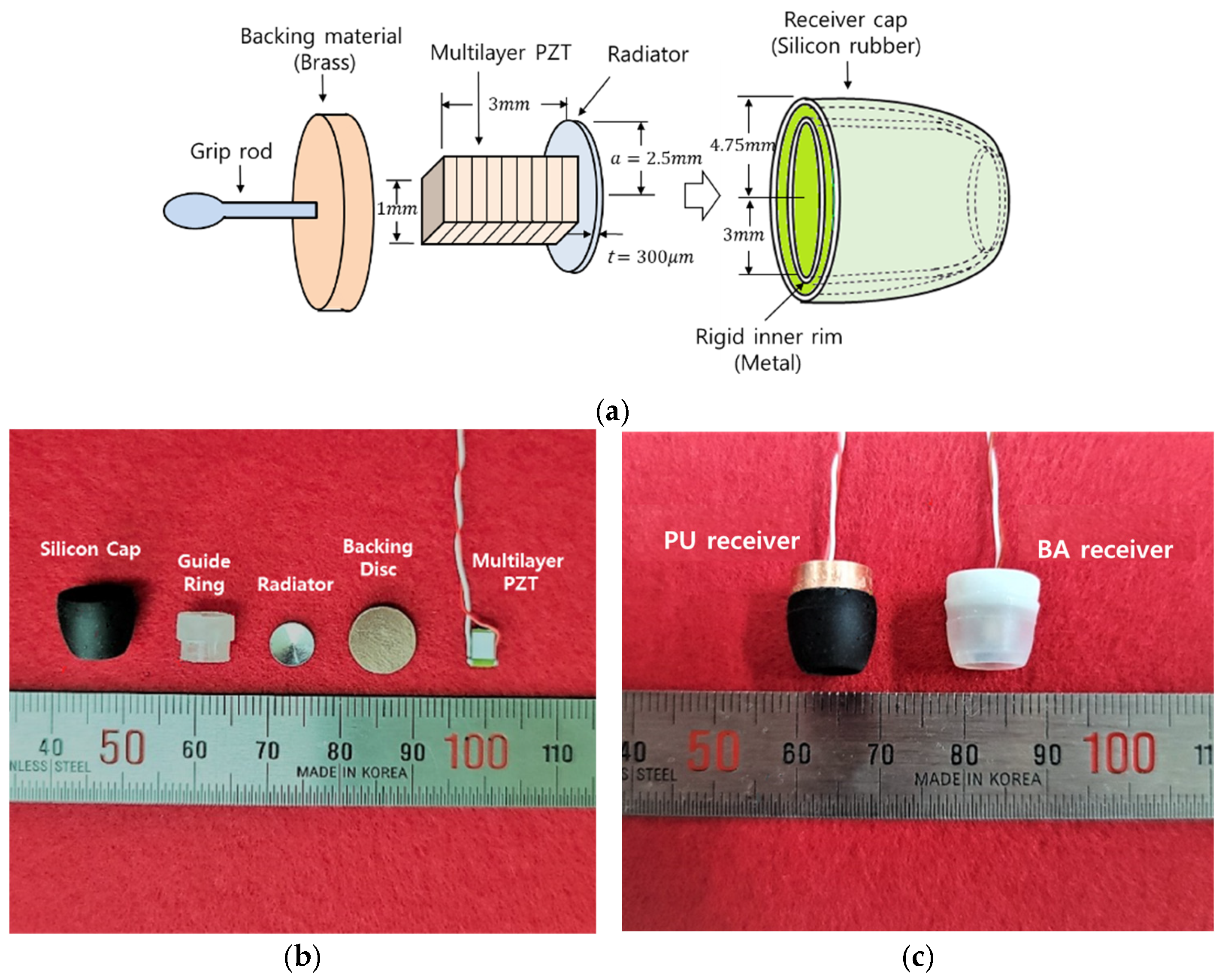
12]. We used multilayer PZT vibrator (5 mm length, 2 × 3 mm cross-section; AE0203D04DF, KEMET, New Taipei City, Taiwan) as the core of the transducer. A 3 mm thick brass backing (acoustic impedance ~37 Mrayl, similar to PZT’s 34.5 Mrayl) was attached to one side using a thin epoxy adhesive (impedance~2.5 Mrayl, thickness < 2 μm). The adhesive used is an epoxy resin with low acoustic impedance (z = 2.51 Mrayl) and a thickness of less than 2 μm. A silicone cap for the receiver with an outer diameter of 9.5 mm was attached to the backing material body with the radiator side as the inlet. When the silicone cap is inserted, the thin sleeve rubber of the cap bends, making it possible to insert it into an ear canal with a diameter of 8 mm. When inserting the receiver, a plastic guide ring with an inner diameter of 6.2 mm was inserted to prevent the vibrating radiator from coming into contact with the silicon cap. The left side of
Figure 1c shows an ultrasonic hearing aid receiver, and the right side shows a BA (balanced armature) receiver (FK-23451, Knowles, Itasca, IL, USA) for comparison, placed in a silicon cap of the same size.
When the distance between the receiver and the eardrum is 6 mm and the diameter of the eardrum is 8 mm, the divergence angle for the sound from the receiver to reach the 4 mm diameter area from the center of the eardrum is approximately 36°. When the diameter of the sound radiator is 5 mm, in order to maintain a divergence angle of 36°, a carrier frequency of approximately 130 kHz is required according to Equation (1).
where
θ is the divergent angle in radians,
λ is the wavelength of the sound, and
D is the diameter of the radiator.
2.2. Parametric Audio Modulation Method for the Hearing Aid
In the parametric audio system, the audio is generated because of the interference of the carrier frequency and sideband signals frequency due to the nonlinearity of the air when the strong ultrasonic wave modulated by the audio signal is radiated from the transducer. To generate a focused beam in the hearing aid receiver, it is necessary to select an ultrasonic modulation method suitable for this. Parametric audio is a secondary sound generated by air nonlinearity when a strong ultrasonic beam travels, with the characteristics of a sharp audio beam. So far, several parametric audio-modulation schemes have been developed for directional loudspeakers [
13,
14]. Since the DSBAM (double-sided band-amplitude modulation) method was first implemented by Yoneyama et al. [
15], SRAM (square root amplitude modulation), SSBAM (single-sided band-amplitude modulation), pulse width modulation (PWM), etc., have been proposed to lower THD and implement an effective system. PWM is inexpensive and easy to implement, but it is not suitable for hearing aids because of its high THD. In this study, the authors decided to use the SRAM method, which is easy to implement and has low THD. In the SRAM approach, the audio signal’s envelope is pre-processed by taking its square root before modulating the ultrasonic carrier. This square root pre-modulation, based on Berktay’s far-field solution, effectively linearizes the demodulation process and thereby reduces undesirable harmonic distortion in the audible output.
That is, the audible signal spectrum,
, among the various signals in which the nonlinear density modulation of air occurs, corresponds to the difference frequency component between the carrier,
, and the sideband’s signal spectrum,
. Parametric audio has a characteristic in which the audio power gradually increases with distance from the radiator and then attenuates, and is transmitted with high directivity. At this time, when the sound pressure of the SRAM wave is
, the sound pressure,
, of the resulting output audio signal can be described by the following Equation (2), which is well known as far-field solution, as described in [
16]:
where
β is the nonlinearity coefficient of the air;
p₀ is the amplitude of the ultrasonic carrier wave (primary pressure);
S is the cross-sectional area of the ultrasonic beam;
α is the acoustic absorption coefficient of the air;
ρ₀ is the air density;
c is the sound velocity in the air;
r is the propagation distance from the source;
m(
t) is the modulation envelope of the audio signal.
Here, when the distance,
, from the sound source is very small,
can be substituted. If the constant term of Equation (2) is summarized and expressed simply as
, it can be seen that the output sound pressure,
, is proportional to the second-order time-derivative value of the squared envelope,
as shown in the following equation:
In general, hearing aid receivers are designed to have the ability to provide an audio sound of up to 100 dB SPL to the hearing-impaired people using them. At this time, it is necessary to know how much primary sound pressure, , is required to generate a parametric sound pressure of 100 dB SPL, as an ultrasonic radiator of a size that can fit inside the receiver. For this, assuming 80% modulation at 1 kHz, we must calculate the required in Equation (3).
In Equation (2), except for the
term and the
term, all of the terms can be treated as proportional constants, so the proportional constant is calculated as
using the parameter values shown in
Table 1. A sound pressure of 100 dB SPL corresponds to
, and since the carrier is AM-modulated, the amplitude of the envelope,
, is substituted with
t). As a result,
dB SPL is obtained from Equation (3). Then, the first ultrasonic pressure,
, must be supplied to obtain an audible intermediate sound pressure,
p(
t), of 100 dB SPL. This is achieved by applying a carrier ultrasonic wave of 130 kHz to a vibrating radiator with an ultrasonic radius of 3 mm. This is calculated to be approximately 132 dB SPL.
2.3. Measurement of Frequency Characteristics
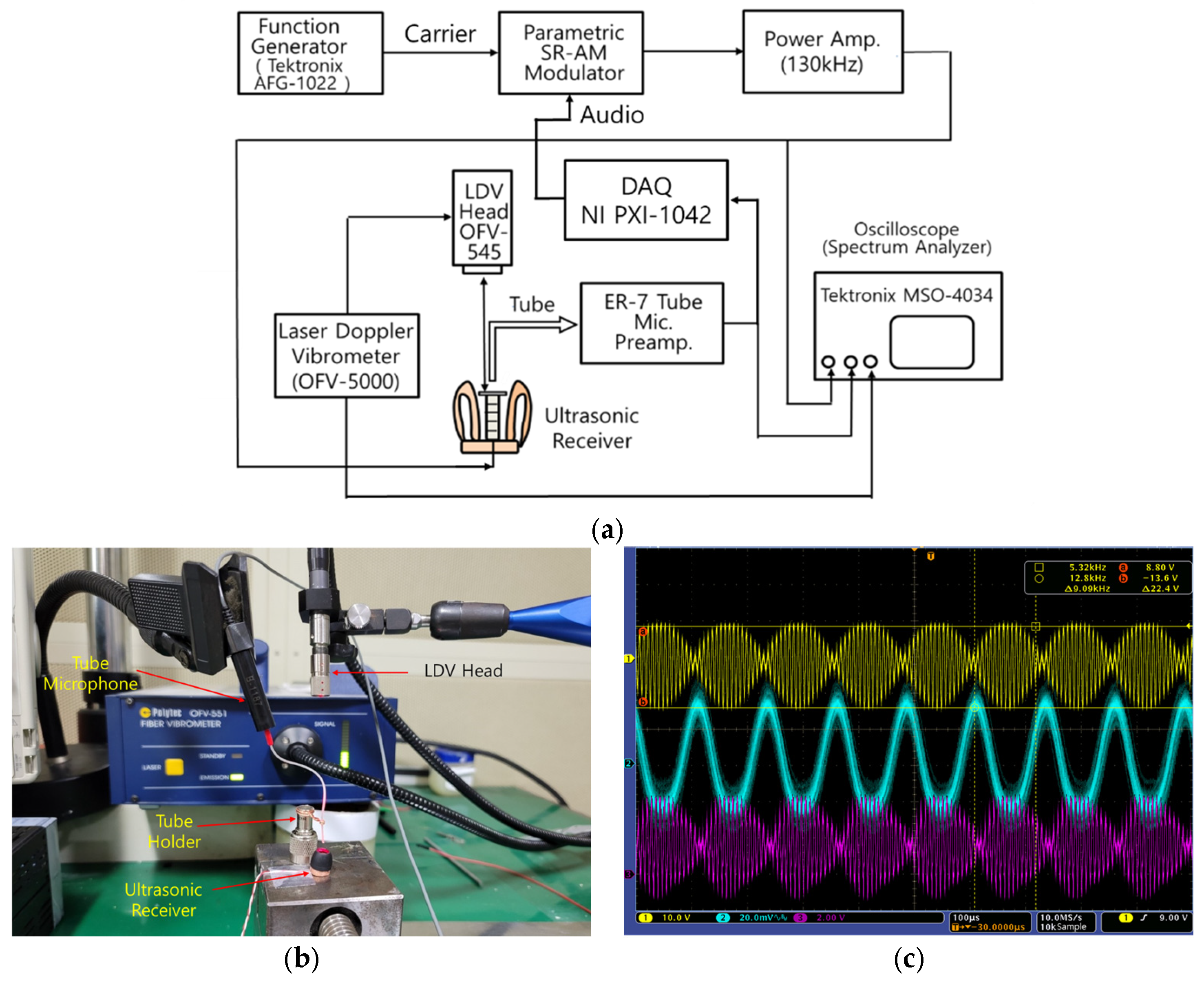
To measure the frequency characteristics of the ultrasonic receiver using the proposed ultrasonic parametric audio modulation approach, a data acquisition system (DAQ, NI PXI-4461 in NI PXI-1042; National Instruments, Austin, TX, USA), LDV (laser Doppler vibrometer) (OFV-5000 and OFV-545, Polytec, Karlsbad, Baden-Württemberg, Germany), and a probe microphone system (ER-7C, Etymotic Research, Elk Grove Village, IL, USA) were connected to form the device shown in
Figure 2a. After taking the root square of the audio signal generated by the DAQ system, the SRAM signal was obtained by producing it with the carrier signal. For this, two multiplier ICs (MPY634, Burr Brown, Tucson, AZ, USA) were used. The modulation rate was set to
m = 0.8, and the characteristics of the parametric modulator, in which THD (total harmonic distortion) increases when it is too high, were considered. The output signal of the 1 Vrms SRAM modulator was amplified to a level capable of generating a parametric audio signal and supplied to the PU receiver. For this purpose, RF power with a voltage gain of 30 dB, an output of 5 W, and a cutoff frequency of 1 MHz was used. For ease of experimentation, the amp used was a push–pull amplifier composed of 2SA1012 and 2SC1814 power transistors, without a class D amp, which requires a switching stage and low-pass filter.
Figure 2b shows the configuration of the experimental setup installed in a soundproof chamber with a noise level of less than 50 dBA. It shows the tube of the laser beam head and the probe microphone of the LDV installed to measure the sound pressure and vibration amplitude generated from the radiator by supplying the SRAM signal to the PU receiver.
Figure 2c presents the oscilloscope waveform captured at this time. The first image is a diagram of the SRAM voltage (yellow) applied to the receiver, the second presents the ER-7 microphone output voltage (cyan), and the third presents the LDV output waveform (magenta).
Figure 3 shows the sensitivity characteristics of the PU receiver measured at distances of 3, 6, and 10 mm, and is plotted along with the frequency characteristics of the BA receiver at a distance of 10 mm for comparison. A 130 kHz SRAM signal with a modulation rate of 80% was applied to drive the PU receiver. In order to avoid changes in vibration characteristics due to the limitations of the amplifier and the heat generation of the PZT element used, a 10 V
peak SRAM signal was applied for the test, and the power supplied at this time was 1.3 mW, and the same power was supplied to the BA receiver. When applying 10 V peak to the receiver, the voltage amplitude required to obtain 100 dB SPL sound was calculated as 33 V; to avoid changes in the vibration characteristics due to the limitations of the amplifier and heat generation of the PZT element used, a 10 V
peak was applied and tested.
For use as a practical PU receiver, a flat frequency characteristic from low frequencies to 10 kHz is desirable. However, for the measured frequency characteristics, sound pressure below 500 Hz was very low; from this frequency to 10 kHz and higher frequencies, the sound pressure increased dramatically and then decreased, reflecting the frequency characteristics of a typical parametric audio system. Regardless of l, various peaks were observed between 0.5 and 10 kHz, and the range of peak values was also larger than that of the BA receiver. A section in which the sound pressure measured at a distance greater than 3 mm from the radiator surface exceeded the sound pressure measured at 3 mm was also observed. Additionally, the average sound pressure in the range of 1 to 10 kHz was about 70 dB SPL.
The BA receiver has a maximum sound pressure at 2~3 kHz and slope of −20 dB/decade, and the gain decreases as it goes to high frequencies. However, the proposed PU receiver has an increase in gain as it goes to high frequencies and exceeds that of the BA receiver at frequencies higher than 3 kHz, as predicted. This finding implies that the receiver can be used by people with impaired sensorineural hearing who require a large high-frequency gain above 2 kHz. It is necessary to add a pre-emphasis filter to enhance the low-frequency gain because the sensitivity is lower than that of a BA-type receiver at 3 kHz or less. To be satisfactory as a practical hearing aid output device, an output sound pressure level of 100 dB at 1 kHz is required. However, the experimental result reached only 60 dB SPL. The main reason for this shortcoming is likely the inability to conduct closed-field experiments, such as those in the external auditory canal, due to limitations in the experimental setup. Additionally, the failure to apply the required high voltage may have contributed to the lower SPL. Nevertheless, the frequency characteristics of the output device are expected to remain unchanged, regardless of the experimental setup.
2.4. Directivity Measurement
Although this receiver uses ultrasonic waves, our goal was to focus an audible-band sound beam, so we measured the directivity of the parametric audio generated by the ultrasonic waves using an audible-band sound pressure meter. We measured the directivity of a beam a very short distance from a radiator with a diameter of only 6 mm. The microphone aperture of the audio level meter must be very small to measure the directivity of the beam. Therefore, in this experiment, a probe microphone system with a 0.5 mm diameter tube was used to ensure sufficient beam measurement resolution.
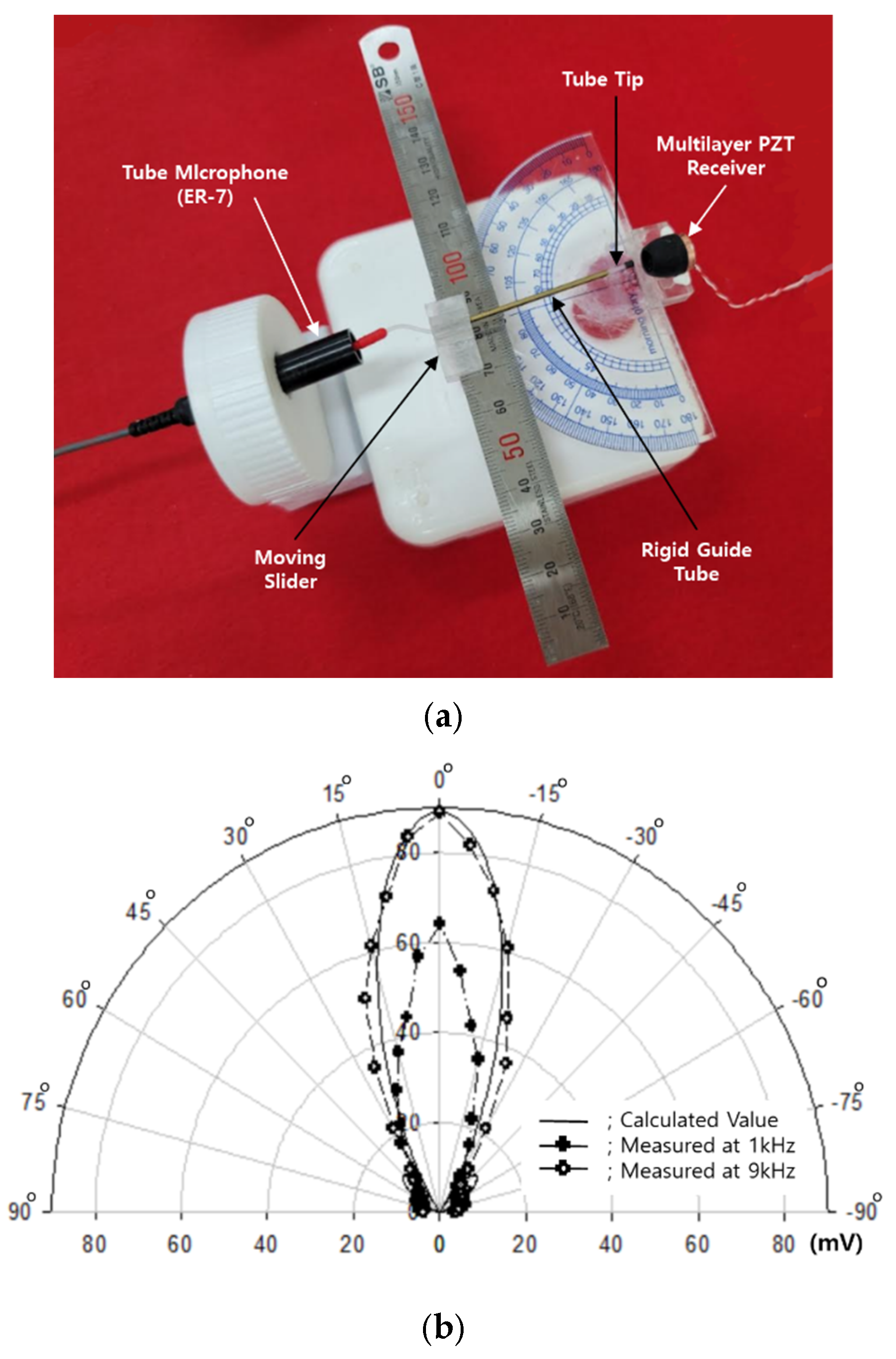
We also used the small directivity measuring device shown in
Figure 4a to measure the directivity within a few centimeters. The silicone tube connected to the measurement microphone is flexible, so this directivity-measuring instrument involved inserting a rigid guide tube with an inner diameter of 1 mm. We used a slider with a groove depth of 7 mm and groove width of 2 mm that can be moved by inserting a protractor or ruler to measure the directivity by moving in circles or straight lines.
The diameter of the radiator was only 6 mm, so it was difficult to measure the directivity of an audio beam radially at a distance of 6 mm or less from the radiator. Therefore, at 6 mm, we measured the sound pressure of the beam cross-section across a straight line. At a distance of 10 mm, we measured directivity in the radial direction. Measurements in the radial direction were determined by dividing the sound pressure measured by moving the slide at 5° intervals in the angular range of ±90° by the value of the sound pressure at the center of the ultrasound beam (0°).
Figure 4b presents the measurements in the radial direction at 1 and 9 kHz; the results revealed that the measured sound pressure level was in good agreement with the calculated directional pattern value.
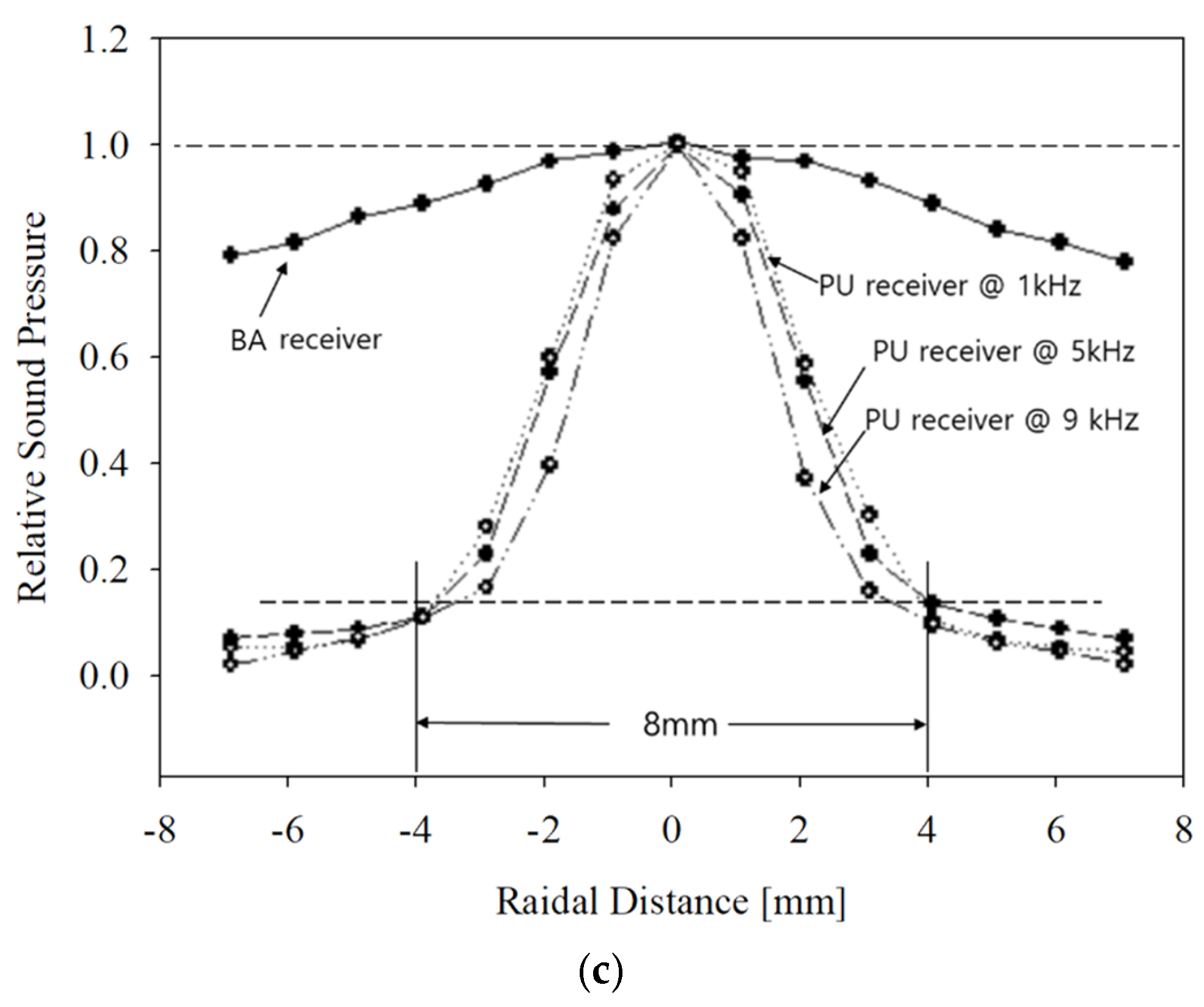
Figure 4c presents the measured sound pressure profile, i.e., the axial sound pressure distribution of the cross-section of the audio beam of the PU and BA receivers at 1, 5, and 9 kHz. At the time of measurement, a 100 mV signal was applied to a BA receiver; it was normalized to the maximum sound pressure at the center of the beam and compared with the PU receiver.
During measurement, 10 V was applied to the PU receiver and 100 mV to the BA receiver because the BA receiver is driven by a low-voltage current due to its low internal resistance, while the PU receiver is a potential driving element with a very large internal resistance. The results confirmed that the sound generated by the SRAM modulated ultrasound signal focused more than 95% of the energy within the diameter of the eardrum at 8 mm. To characterize the intrinsic beam pattern, directivity measurements were performed under free-field conditions (i.e., without a baffle or ear). This setup follows standard practices in transducer characterization [
13]. Previous studies also evaluated ultrasonic hearing devices in free-field or quasi-free-field setups [
17].


