Abstract
The accurate identification of coal and rock at the mining face is often hindered by adverse underground imaging conditions, including poor lighting and strong reflectivity. To tackle these issues, this work introduces a recognition framework specifically designed for underground environments, leveraging joint migration and enhancement of multidimensional and full-scale visual representations. A Transformer-based architecture is employed to capture global dependencies within the image and perform reflectance component denoising. Additionally, a multi-scale luminance adjustment module is integrated to merge features across perceptual ranges, mitigating localized brightness anomalies such as overexposure. The model is structured around an encoder–decoder backbone, enhanced by a full-scale connectivity mechanism, a residual attention block with dilated convolution, Res2Block elements, and a composite loss function. These components collectively support precise pixel-level segmentation of coal–rock imagery. Experimental evaluations reveal that the proposed luminance module achieves a PSNR of 21.288 and an SSIM of 0.783, outperforming standard enhancement methods like RetinexNet and RRDNet. The segmentation framework achieves a MIoU of 97.99% and an MPA of 99.28%, surpassing U-Net by 2.21 and 1.53 percentage points, respectively.
1. Introduction
Automatic coal–rock identification is a key enabling technology for intelligent mining, as the coal mining machine and roadheader are critical equipment at the mining face that directly impact production safety and operational efficiency [1,2]. However, due to the influence of harsh underground environments—such as complex geological formations, adverse working conditions, uneven lighting, and heterogeneous coal–rock composition [3]—the acquired coal–rock images often suffer from degraded visual quality, including low illumination, weak edge features, uneven brightness, low contrast, and significant noise, which pose serious challenges for accurate recognition.
Coal–rock image recognition technology has advanced significantly through the application of deep learning models [4,5]. For example, Hua Tongxing et al. [6] employed Faster R-CNN for coal–rock classification and coal seam localization. Zhang Bin et al. [7] combined YOLOv2—a target localization approach based on regression-driven object detection—with a linear imaging model for identifying coal–rock formations in underground environments. Si Bui et al. [8,9] proposed coal–rock recognition methods for fully mechanized mining faces, utilizing an improved U-Net architecture and a deep convolutional neural network, respectively. Wang Xing [10] addressed the data scarcity problem by introducing Var-ConSinGAN for sample generation and feature migration. Gao Feng et al. [11] introduced a tower pooling-based coal–rock recognition framework, while Yan Zhirui et al. [12] proposed an improved DeeplabV3+ model with transfer learning for interface segmentation. Sun Chuanmeng et al. [13,14] developed methods integrating an enhanced YOLOv3 with cubic spline interpolation and proposed a segmentation framework incorporating attention mechanisms and full-scale connectivity. To capture detailed structural variations, the complete local binary pattern (CLBP) was adopted for modeling coal–rock image features [15]. Wang Chong [16] and Wang Yanping [17] designed humanoid intelligent control strategies for mining height regulation, combining fuzzy inference and particle swarm optimization with improved YOLOv3-based boundary detection. Xiaoxue et al. [2] applied a U-Net-based model incorporating the ResNeSt module and channel attention for semantic segmentation. Xiaoyang Liu et al. [18] proposed a multi-scale feature fusion method based on local binary patterns and convolutional neural networks. You Keshun et al. [19,20] utilized DeepLabV3+ with a sparrow search algorithm for mineral processing image feature extraction, and further improved YOLOv5 to enhance the detection accuracy of mineral separation points under complex operational conditions.
However, most of these programs use more traditional image-enhancement methods to preprocess coal–rock images, so the enhancement effect is limited and insufficient for the recognition network. Most coal and rock image research is in the target detection field, the classification of coal and rock images is still classified by blocks, and the data of coal and rock areas are still not precise, thereby providing incorrect information to the coal mining machine so it cannot realize the precise cut-off. To address this issue, we propose a recognition model tailored for underground coal–rock scenes that integrates joint feature migration and enhanced representation across multidimensional and full-scale visual spaces. A public dataset was employed to train this network and enhance the generalizability of the model to cope with the harsh underground coal mine environment. To overcome the uneven brightness in the image caused by unnatural parallel light irradiation in the coal mine, the multi-scale module enhances the brightness of features under different sensory field ranges to prevent possible local overexposure or local underexposure. The NR-Transformer module performs multidimensional noise suppression by capturing long-range dependencies within the image, enabling the network to achieve pixel-wise segmentation on low-quality coal–rock data collected from underground mining environments. The encoder is designed to extract deep semantic representations through a combination of convolutional pooling layers, the Res2 module, and a multi-channel residual attention mechanism. This attention mechanism, integrated with dilated convolution, enhances low-level feature extraction, supported by a full-scale connectivity structure to preserve contextual information. The decoder fuses and analyzes the different scale features through bilinear interpolation upsampling, a convolutional module, and full-scale connectivity architecture. The flowchart of coal–rock recognition is shown in Figure 1.
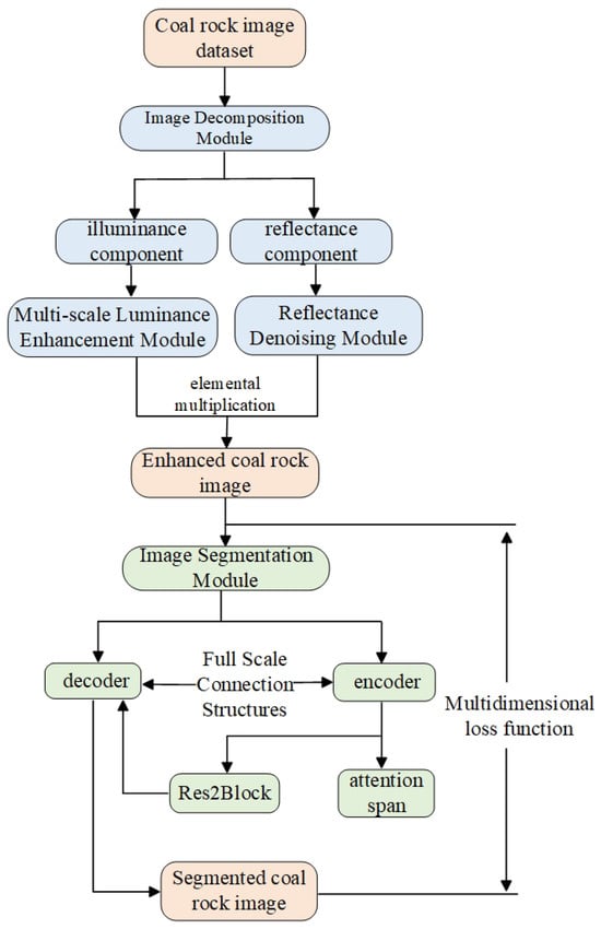
Figure 1.
Flow chart for coal–rock identification. The coal–rock image dataset is first fed into the image decomposition module to obtain the enhanced coal–rock image and then the pixel-level segmentation is realized by the image segmentation module.
2. Relevant Theory
2.1. Characterization of Coal–Rock Images
Adverse conditions in underground coal mines—such as darkness, reflections, uneven illumination, occlusions, shadows, water drenching, coal dust, and mechanical vibrations—degrade the visual quality of coal–rock images. These factors result in low illumination, weak edges, poor contrast, and non-uniform brightness, all of which hinder effective feature extraction and accurate recognition. Therefore, enhancing image quality and emphasizing target object features (e.g., coal or rock) is essential for resolving these technical challenges.
The multidimensional image-enhancement network proposed in this paper improves both reflectivity and illumination, while effectively mitigating common defects such as halo artifacts and overexposure, thereby optimizing the overall image quality. One of the core difficulties in automated coal–rock recognition lies in designing a deep learning model capable of robustly capturing the semantic differences between coal and rock, as well as effectively modeling their stacked spatial relationships and enabling stable error backpropagation.
To address this, the proposed model adopts an encoder–decoder architecture augmented with a full-scale connectivity structure. To support precise segmentation under challenging conditions, the framework incorporates a multi-channel attention module with dilation to focus on informative features, a Res2Block structure for capturing multi-scale patterns, and a comprehensive loss function that facilitates pixel-level guidance during training on low-quality underground coal–rock images.
2.2. Image Decomposition Module
Retinex theory suggests that the human visual perception of color is largely influenced by the object’s reflectance properties across different wavelengths, rather than by the absolute level of incoming illumination. This effect, referred to as color constancy, indicates that an object’s perceived color tends to remain consistent under varying lighting conditions. Based on this principle, the observed image can be mathematically decomposed as follows:
where represents the light intensity image irradiated onto the object, which determines the pixel intensity range of the final captured image; represents the object’s intrinsic ability to reflect light, which is unaffected by external factors and directly determines the color, texture, and other visual characteristics of the final image. To enhance the quality of the original image, the low-illumination coal–rock image is decomposed into its reflectance and illumination components. However, traditional enhancement networks are inadequate for handling severely degraded images caused by the complex and harsh underground environment (Figure 2). In the proposed method, the low-light coal–rock image is first processed by an image decomposition module. The resulting reflectance map is then passed into a reflectance denoising module, which incorporates a Transformer-based structure to remove noise artifacts that may affect subsequent segmentation. Meanwhile, the illumination component is input into a multi-scale brightness-enhancement module that adaptively enhances brightness at different spatial scales, effectively preventing local overexposure resulting from uneven lighting in the original coal–rock image. Finally, the enhanced coal–rock image is reconstructed by performing element-wise multiplication between the outputs of the reflectance denoising module and the multi-scale brightness-enhancement module.
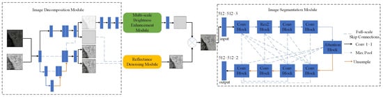
Figure 2.
Network model structure. The network consists of four parts: image decomposition module, multi-scale brightness-enhancement module, reflectivity denoising module, and image segmentation module.
2.3. Reflectance Denoising Module
The Transformer structure used for image denoising, referred to as the Noise Reduction Transformer (NR-Transformer), is designed based on the Vision Transformer (ViT) architecture [21], as illustrated in Figure 3. Unlike conventional Transformer models that embed images using fixed-size patches at the input stage, this structure embeds the feature maps at the pixel level within a separate Transformer module. This allows for more comprehensive aggregation of multi-scale feature information and more effective suppression of global noise signals. However, the original ViT architecture lacks convolutional layers, resulting in a weaker feature extraction capability compared to CNNs. This limitation often leads to slow convergence during training and necessitates larger datasets and more training epochs. Although the self-attention mechanism involves fewer trainable parameters, it introduces significant computational overhead, thereby increasing the network’s runtime and degrading its real-time performance. To address these issues, a hybrid CNN+Transformer structure is adopted in the reflectance denoising module. By combining the localized feature learning capabilities of convolutional networks with the global dependency modeling strength of Transformer architectures, this approach effectively mitigates noise of different granularities across multiple spatial scales.
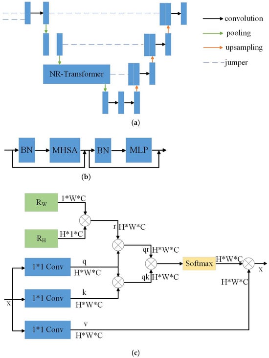
Figure 3.
NR-Transformer for denoising networks. (a) The reflectivity denoising module, (b) the Transformer body structure, and (c) the multiple attention mechanism.
2.4. Multi-Scale Brightness-Enhancement Module
The multi-scale brightness-enhancement module proposed in this paper is inspired by the Pyramid Scene Parsing Network (PSPNet), introduced by Zhao et al. in 2016 [22]. In their work, the authors proposed a pyramid pooling module (PPM), which integrates multiple receptive fields by performing pooling operations on regions of varying sizes and strides. Feature maps from different receptive field scales are then fused through upsampling, concatenation, and convolution operations. Although the pooling layer effectively enlarges the receptive field, it may result in significant information loss, leading to blurred boundaries and color inconsistencies in the enhanced image. To address this issue, we propose a multi-scale brightness-enhancement module based on hybrid dilated convolution (Figure 4), which increases the receptive field while mitigating the loss of critical feature information.
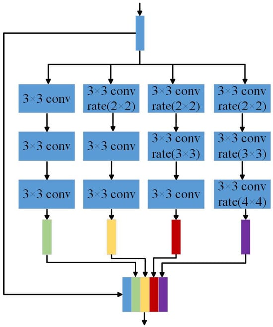
Figure 4.
Multi-scale brightness-enhancement module.
Hybrid dilated convolution enables a more effective preservation of pixel-level information across different spatial locations in the feature map by superimposing dilated convolutions with varying dilation rates. Without increasing the number of parameters, this design retains more fine-grained details from the original feature map and reduces the likelihood of local enhancement artifacts during brightness adjustment. The proposed multi-scale brightness-enhancement module aggregates feature information from four different receptive fields to perform adaptive brightness enhancement across multiple spatial scales, thereby addressing the issue of non-uniform illumination commonly found in coal–rock images. Specifically, the first convolutional branch employs three consecutive standard convolutional layers with kernels, resulting in an effective receptive field size of 7. The second branch consists of one dilated convolution with a dilation rate of 2, followed by two standard convolutions, yielding a receptive field of 9. The third branch includes three dilated convolutions with dilation rates of 2 and 3, along with one standard convolution, resulting in a receptive field of 13. The fourth branch utilizes three dilated convolutions with dilation rates of 2, 3, and 4, achieving a receptive field size of 19. The resulting feature maps from all branches are fused via a convolutional layer to construct the final multi-scale luminance enhancement module.
The dilation rates (2, 3, and 4) adopted in the proposed module were determined through empirical analysis and limited grid-based experimentation. Preliminary tests showed that smaller dilation rates (e.g., 1) failed to provide adequate receptive field coverage, leading to insufficient context aggregation in uneven lighting conditions. Conversely, larger dilation rates (e.g., 5 or above) introduced aliasing artifacts and degraded boundary sensitivity. Therefore, dilation rates of 2, 3, and 4 were selected as a balanced configuration that effectively captures multi-scale contextual information while maintaining structural coherence and computational efficiency.
2.5. Image Segmentation Module
The image segmentation module adopts an encoder–decoder architecture as its backbone to extract semantic features of coal–rock structures. This architecture balances deep feature stacking with effective error backpropagation, enabling the network to automatically learn rich semantic feature representations through supervised training. As illustrated in Figure 2, the segmentation module consists of two primary components: the encoder and the decoder.
The encoder is designed to capture rich semantic information through layered convolutional pooling, multi-scale processing via the Res2 module, and attentive feature refinement using dilated convolution. The Res2 module enhances multi-scale feature extraction without increasing the overall parameter count by dividing feature map channels into subgroups and assigning distinct receptive fields across new dimensions. This architecture enhances the network’s ability to capture diverse features and broadens its receptive field.
The attention module further strengthens feature discrimination by assigning higher weights to relevant features across different scales. This is achieved through a multi-channel design that incorporates dilated convolutions with varying dilation rates, thereby improving the retention of informative features. At the highest encoding layer, the network produces a feature map with spatial dimensions reduced to of the original input image.
The decoder reconstructs the full-resolution prediction by fusing multi-scale features through bilinear interpolation, a convolutional module, and a full-scale connectivity structure. This structure enables the integration of features from different scales and semantic depths, effectively compensating for potential feature loss during encoding. The final output from the decoder is processed using a Softmax layer and then restored to the original image resolution to perform fine-grained segmentation on low-light coal–rock data.
2.6. Res2Block
The ResBlock effectively mitigates the problems of vanishing and exploding gradients that often occur in deep networks due to stacked convolutional layers during backpropagation. As illustrated in Figure 5, the residual block comprises three convolutional layers: a convolution is used to adjust the number of input feature map channels; a convolution is responsible for feature extraction; and a residual connection is employed at the output to merge the input with the processed features. This configuration enables the network to extract deeper features while simultaneously preserving shallow features from earlier layers.
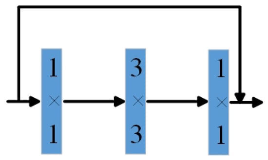
Figure 5.
Res Block module.
The Res2Block modifies the traditional residual block by replacing the standard convolutional layer with a structure capable of multi-scale feature extraction, as illustrated in Figure 6. It introduces a new dimension, referred to as scale, in which the input feature map is split along the channel dimension, and each subset is treated as an independent scale. Convolution is applied to all scale groups except the first. Additionally, each group is connected to its preceding group through a residual connection after convolution, allowing for progressive feature aggregation across scales. The computation process is defined by the following formula:
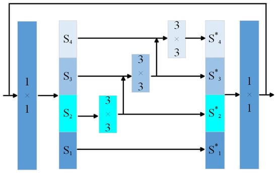
Figure 6.
Res2 Bolck module.
Here, denotes the feature map obtained after channel splitting, while refers to the corresponding output following the convolution operation. The notation represents a convolutional layer.
In the Res2Block, each scale performs one additional convolution operation relative to the output of the preceding scale. The resulting feature maps, each having undergone a different number of convolutions, are then concatenated to form the final output. This design facilitates the extraction of multi-scale semantic information, enabling the encoder to capture coal–rock features at various levels of abstraction. Moreover, it significantly expands the network’s receptive field, thereby enhancing its ability to detect and represent features across different spatial scales.
2.7. Attention-Based Multi-Channel Feature Refinement Module Enhanced by Dilated Convolution
Due to the harsh conditions of underground coal mine environments, the acquired coal–rock images often contain a considerable amount of noise. As the depth of the network increases, some of this noise tends to persist within certain channels, ultimately impairing the accuracy of the final segmentation results. Feature selection is facilitated by an intermediate attention mechanism, which is inserted between the encoder and decoder to mitigate noise impact and improve discriminative representation learning. Specifically, a channel-wise attention module (SEBlock) is employed to automatically evaluate the importance of each channel. By adaptively adjusting channel weights, the network enhances the extraction of meaningful features while suppressing irrelevant or noisy information.
First, the SEBlock uses global pooling to compress the feature map of each channel into a single real number that represents the global feature information. The formula is as follows.
The variables W and H represent the spatial dimensions—width and height—of the feature map, while indicates the pixel intensity value at position .
ReLU activation is applied to the global features, followed by sigmoid gating to generate the attention weight within the range . The equation is shown below.
In this context, denotes the ReLU activation function, and stands for the Sigmoid activation function. The symbols and refer to two fully connected layers positioned prior to these activation functions. Specifically, the first layer reduces the number of global feature channels to one-sixteenth of the original size, and the second restores it back to its initial dimensionality. This compression–expansion structure helps reduce computational complexity while facilitating the integration of information across different channels.
Finally, the attention mechanism’s feature vector is multiplied by the original feature map along the channel dimension. To prevent information loss, a residual structure is used to add the original feature map to the result. The calculation formula is as follows.
Thus, the residual attention structure is constructed, as shown in Figure 7.
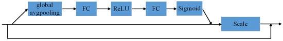
Figure 7.
Residual attention structure.
While the SEBlock is effective in capturing globally salient features, it exhibits limitations in mitigating localized noise interference. Additionally, its global feature suppression strategy may unintentionally eliminate informative details that are essential for accurate representation. To overcome these shortcomings, we propose a multi-channel residual attention module that integrates dilated convolution. This module is specifically designed to attenuate fine-grained noise while preserving crucial feature representations across multiple spatial scales. The structure of the proposed module is shown in Figure 8.
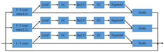
Figure 8.
Multi-channel residual attention module fused with dilated convolution.
In this paper, a three-branch parallel structure is employed to construct the attention mechanism at multiple observation scales. Specifically, it consists of a convolution, a dilated convolution with a dilation rate of 2, and a dilated convolution with a dilation rate of 4. This configuration enables the network to capture attention features at different receptive field sizes, thereby effectively suppressing diverse types of noise signals. By integrating dilated convolutions with varying dilation rates, the proposed multi-channel residual attention module suppresses ineffective information across multiple scales, reduces noise interference, and enhances the representation of salient features. Furthermore, the inclusion of a residual connection helps preserve shallow feature information, which improves both the accuracy and robustness of the model.
3. Network Loss Function
A dedicated loss function is defined for the image decomposition module, the reflectance denoising module, and the multi-scale brightness-enhancement module, as detailed in the following section.
3.1. Image Decomposition Module Loss Function
According to Retinex theory, an object’s reflectance remains invariant under different lighting conditions. Therefore, the reflectance components extracted by the decomposition network from both high- and low-illumination images should be consistent. To enforce this property, a reflection consistency loss is introduced to measure the discrepancy between the reflectance maps of the two images. The loss is defined as follows:
where , denotes the decomposition to obtain low- and high-illumination reflectance maps, respectively, and denotes the L2 paradigm. This loss function is smaller when a smaller gap between the reflection maps is obtained by decomposition. The light image obtained by decomposition should be smooth and continuous, so the light smoothing loss is also needed:
where ▽ denotes the first-order derivative operator in both horizontal and vertical directions; represents the luminance maps obtained from the decomposition of low- and high-illumination images; denotes the original low- and high-illumination input images; and is a positive constant introduced to prevent division by zero, which is set to 0.01. The notation refers to the L1 norm. When the gradient magnitude is large—such as at image edges—the constraint on illumination smoothness is relaxed. In contrast, for regions with small gradients (i.e., structural interiors), stronger smoothing is enforced to reduce the loss. This ensures that the illumination map maintains local smoothness while preserving the overall structural consistency of the scene. The corresponding loss function is formulated as follows:
where denotes the constraint constant, and c denotes the constraint constant; here c is taken as 10. When M is close to 0 or infinity, then the light map is in the smooth stage, when M is in the more intermediate range, then the light map is in the edge stage and the low-light map is similar to the high-light map, ensuring that the light map is in the same overall structure. Finally, since the decomposition obtains the reflection and light maps according to Retinex theory, the result after multiplication should be consistent with the original image, so it is also necessary to reconstruct the loss as follows:
Finally, these losses form the loss function of the decomposition network, which can be combined according to certain weights as follows:
3.2. Reflectance Denoising Module Loss Function
Low-illumination coal–rock images captured in underground environments typically contain significant noise. As a result, the reflectance maps decomposed from these images must undergo denoising to align with the cleaner reflectance maps derived from high-illumination images. Therefore, the high-illumination reflectance maps are treated as ground truth for the design of the loss function. After denoising, the output reflectance map should preserve the overall structure and remain as consistent as possible with the high-illumination reference in terms of both visual and structural characteristics. Accordingly, the loss function for the reflectance denoising network is composed of two terms: one to enforce structural consistency and another to ensure image-level similarity. The corresponding loss function is defined as follows:
3.3. Multi-Scale Luminance-Enhancement Module Loss Function
The loss function of the luminance enhancement network also takes the high illumination obtained from decomposition as the real standard, and similarly, the luminance-enhanced light image should be consistent with the light map decomposed from the high-illumination image under the structure as well as the overall characteristics, which is calculated by the following formula:
where denotes the light map obtained after luminance enhancement. The final loss function of the overall network is composed of the weighted sum of these three components as follows:
where , , and denote the weight coefficients of the final loss function indicating the degree of influence of the final imaging effect of different loss functions, which were finally set to 0.5, 0.3, and 0.2, respectively.
The weighting coefficients , , and used in the total loss function were selected based on empirical tuning and convergence behavior observed during training. A coarse grid search was conducted to avoid dominance of any single loss component. Prioritizing the image decomposition loss ensures that the core structural fidelity of the enhanced image is preserved, while moderate emphasis on reflectance denoising and luminance consistency helps balance overall image quality and segmentation readiness. The current setting was found to yield stable convergence, effective suppression of artifacts, and improved segmentation accuracy. More advanced tuning strategies (e.g., Bayesian optimization) may be explored in future work.
4. Experimental Research
4.1. Coal–Rock Image Dataset
Since it is difficult to obtain a sufficiently large number of paired low- and high-illumination coal–rock images in underground environments, a public dataset was used for training, and the proposed model was subsequently tested using real coal–rock images. Specifically, the BrighteningTrain dataset was employed for training, which contains 1000 high-illumination and 1000 corresponding low-illumination images encompassing a variety of object structures. This diversity ensures the generalization capability of the image-enhancement network. All images are in PNG format with a resolution of pixels. Among them, 900 image pairs were used for training and 100 for validation. The experimental test set included 500 low-illumination coal–rock images collected under dim underground mining conditions, as well as 1000 synthetically degraded coal–rock images generated by adding 0.02% Gaussian noise and impulse (salt-and-pepper) noise. Manual annotations were created using the LabelMe version 5.3.1 software to generate pixel-level ground truth labels for evaluating segmentation performance. As shown in Figure 9, the red regions represent coal seams, while the black regions denote rock seams.
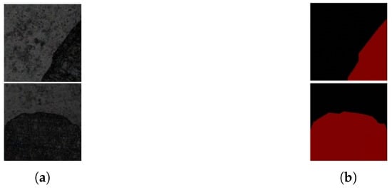
Figure 9.
Dataset labels. (a) the original image; (b) the label image.
Although the proposed model is trained using the publicly available BrighteningTrain dataset, which primarily consists of synthetic low- and high-illumination image pairs, special consideration was given to addressing the potential domain shift between synthetic training data and real-world underground coal mine images. To evaluate the generalization ability of the model, we constructed a testing dataset composed of 500 authentic coal–rock images captured in actual underground environments under poor lighting conditions. Furthermore, we manually augmented this dataset with 1000 additional coal–rock images by injecting Gaussian and salt-and-pepper noise to simulate the diverse interference patterns encountered in real scenarios.
The model architecture is inherently designed to improve robustness against domain discrepancies. The multi-scale luminance-enhancement module adaptively enhances brightness across multiple perceptual fields, mitigating local over- or underexposure under non-uniform lighting conditions. Meanwhile, the NR-Transformer, incorporating long-range attention with convolutional refinement, effectively suppresses structural noise and enhances salient features. These components jointly contribute to enhancing the model’s ability to generalize beyond the training domain.
Although explicit domain adaptation methods, such as adversarial domain alignment, domain-specific normalization, or discrepancy-based losses, are not currently implemented in our framework, we acknowledge their importance and plan to integrate them in future iterations of our work. Specifically, strategies such as fine-tuning with a small amount of labeled underground data, domain-specific feature alignment, or leveraging style transfer for domain translation can be considered to further reduce the performance gap across domains.
4.2. Model Learning and Training
4.2.1. Optimization Algorithm Design
The Adaptive Moment Estimation (Adam) algorithm was selected to improve training accuracy without increasing computational cost. By incorporating both stochastic gradient descent principles and adaptive learning rate strategies, Adam effectively performs mini-batch updates to improve convergence stability and avoid local optimum traps. In addition to maintaining the benefits of SGD, Adam computes both the first-order moment (the mean) and the second-order moment (the uncentered variance) of the gradients to dynamically adjust the step size for each parameter update. To mitigate the oscillation commonly encountered in SGD during updates, Adam introduces a learning rate decay mechanism, allowing the convergence process to proceed more smoothly and autonomously, reducing the need for manual learning rate tuning and facilitating more intelligent convergence toward a global optimum. The overall procedure of the proposed methodology is summarized in Algorithm 1.
| Algorithm 1 Training routine based on adaptive moment estimation |
| Require: Learning rate (e.g., ), numerical stability constant (e.g., ) |
| Require: Exponential decay coefficients , (e.g., 0.9, 0.999) |
| Require: Model parameter set , iteration step |
| Require: Moment vectors , |
| while termination condition is not satisfied do |
| Draw mini-batch with labels |
| Compute gradient: |
| Update biased first moment: |
| Update biased second moment: |
| Bias correction: |
| Bias correction: |
| Compute update step: |
| Apply parameter update: |
| end while |
4.2.2. Training Environment
The training and evaluation of the proposed model were conducted using the TensorFlow GPU framework (version 2.2.0). The Adam optimizer was employed for parameter updates. Key hyperparameter settings are as follows: the learning rate was configured to , with a batch size of 8. An exponential decay rate of 0.95 was applied, and the total number of training epochs was set to 100. Details of the computational environment are provided in Table 1, and the training loss progression throughout the optimization process is visualized in Figure 10.

Table 1.
Hardware and software environment.
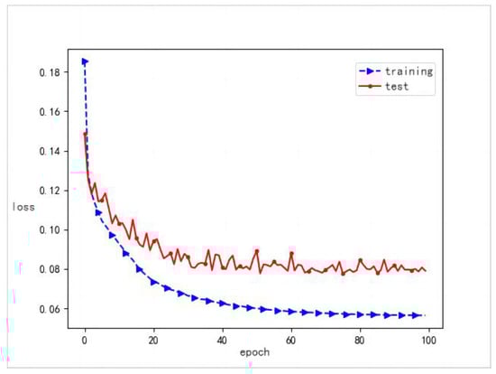
Figure 10.
Visualization of model loss: blue denotes training error, while red indicates validation error over epochs.
4.3. Experimental Results and Analysis
4.3.1. Comparative Experiments of Multi-Scale Luminance Enhancement Modules
The multi-scale luminance-enhancement module was tested with the more common image-enhancement network models Retinexnet [23], RRDnet [24], and EnlightenGAN on a dataset consisting of 500 low-illumination coal–rock images, with PSNR and SSIM selected as the evaluation metrics for quantitative analysis of the model quality. Figure 11 shows from left to right: the low-illumination image, the high-illumination image, the Retinexnet enhancement effect, the RRDnet enhancement effect, EnlightenGAN enhancement effect, the model’s infrastructure enhancement effect, and the model’s enhancement effect. The objective analysis is shown in Table 2. The darker parts of the figure represent coal seams and the lighter parts represent rock seams.
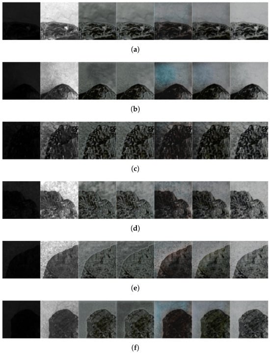
Figure 11.
Comparison of experimental results of coal and rock enhancement images. Subfigures (a–f) show representative samples selected from the dataset, reflecting typical coal and rock interface scenarios.
Table 2.
Comparison of experimental results of enhanced images of coal rock.
The proposed model achieved scores of 21.288 and 0.783 in PSNR and SSIM, respectively, which is better than its infrastructure and the more common image-enhancement models. The model also enhanced the brightness, with the uniform lighting effect close to the natural light and no distortion. Therefore, the model effectively enhanced the low illumination coal–rock image caused by the complex and harsh environment of the coal mine.
The integration of the multi-scale luminance-enhancement module provides significant improvements both quantitatively and qualitatively. As demonstrated by the comparative results in Table 2 and Figure 11, this module yields the highest PSNR (21.288) and SSIM (0.783) scores among all compared methods, indicating its effectiveness in enhancing low-illumination coal–rock images while preserving structural fidelity. More importantly, by fusing features across different perceptual fields via hybrid dilated convolution, the module successfully eliminates localized overexposure and underexposure, leading to a more uniform illumination distribution across the image. This reduces false activations and segmentation errors in subsequent modules. From an engineering perspective, the improved brightness uniformity and contrast restoration significantly enhance the model’s robustness in non-ideal imaging conditions, such as variable lighting, reflective surfaces, or partial occlusions: scenarios frequently encountered in real underground environments.
4.3.2. Comparative Experiments of Image Segmentation Modules
The proposed image segmentation module was compared with several widely used semantic segmentation networks, including DeepLab [25], PSPNet, U-Net, and SegNet [26], using the same training dataset. All models were evaluated on a semantic segmentation task targeting coal–rock images. Due to space constraints, six representative samples are selected for qualitative comparison, as shown in Figure 12. From left to right, the figure displays: the original input image, the ground truth label, the segmentation result of the proposed model, and the results from DeepLab, PSPNet, U-Net, and SegNet, respectively. The proposed segmentation module demonstrates strong performance in handling low-quality coal–rock images from underground mining environments, accurately delineating the boundary between coal and rock seams. In contrast, the baseline models exhibit various deficiencies such as segmentation failures, misclassification, over-segmentation, and significant boundary inaccuracies, indicating limited robustness under challenging conditions. In Figure 12, the red regions denote coal seam areas, while black regions correspond to rock and background areas.
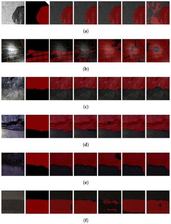
Figure 12.
Comparison of experimental results of coal and rock segmentation images. Subfigures (a–f) show representative samples selected from the dataset, reflecting typical coal and rock interface scenarios.
The improvements in PSNR and SSIM achieved by the multi-scale luminance-enhancement module are particularly evident in low-illumination and high-reflectance scenarios, which are common in underground mining environments. In these cases, traditional enhancement methods (e.g., RetinexNet, RRDNet) tend to either over-enhance bright regions or suppress details in darker areas, leading to degraded visual quality. In contrast, our module maintains brightness uniformity and texture clarity, resulting in higher PSNR and SSIM scores.
Similarly, the segmentation module yields notably higher MIoU and MPA scores, especially in cases with fuzzy coal–rock boundaries or partial occlusion by dust and water mist. These improvements indicate that the proposed model is more robust to visual degradation and better at preserving fine-grained spatial semantics. This translates to improved operational reliability in downstream tasks such as automatic shearer control or real-time coal–rock interface monitoring.
4.3.3. Multi-Scale Luminance-Enhancement Module Ablation Experiments
To assess the individual impact of various components within the network, a series of ablation studies was performed. As shown in Figure 13, the images from left to right include the enhancement result of the low-illumination image, the corresponding high-illumination reference, the enhancement result using the base network structure, the result with the integration of the multi-scale brightness-enhancement module, the result with the incorporation of the NR-Transformer, and the final enhancement result of the complete proposed model. Quantitative comparisons for each configuration are provided in Table 3. In Figure 13, darker regions represent coal seam areas, while lighter regions correspond to rock and background areas.
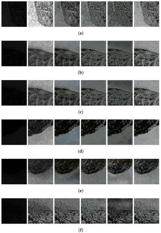
Figure 13.
Comparison of the results of the ablation experiment with the image-enhancement module. Subfigures (a–f) present representative samples selected from the dataset to illustrate the visual differences under various experimental conditions.
Table 3.
Comparison of results of ablation experiments with luminance enhancement modules.
The basic model structure without any enhancements (Group 1) produced the lowest evaluation scores, exhibiting poor image enhancement quality, noticeable distortion, and unstable brightness consistency.
Group 2, which incorporates the multi-scale brightness-enhancement module, achieved improved evaluation metrics over Group 1 without a significant increase in parameter count or computational cost. It provided more uniform brightness and effectively avoided local overexposure and underexposure. However, the resulting image clarity was suboptimal and remained susceptible to minor noise interference.
Group 3, which integrates the NR-Transformer structure, also outperformed Group 1. Due to the absence of convolutional layers, the overall parameter count was reduced, and the enhanced images showed fewer distortions and improved clarity. However, the illumination remained uneven.
Group 4 replaces the multi-scale module with a pyramid pooling module. Compared to Group 2, it resulted in larger performance discrepancies despite its advantage of a smaller number of parameters.
Group 5 utilizes the original Transformer structure. Although it further reduces the parameter count, its enhancement performance was inferior to even the baseline (Group 1), with lower evaluation scores overall.
Group 6 combines the multi-scale brightness-enhancement module (Group 2) and the NR-Transformer (Group 3). This configuration achieved the best overall evaluation metrics, along with reduced parameters and improved computational efficiency. The enhanced images were closest in appearance to the high-illumination ground truth, demonstrating minimal distortion, uniform lighting, and a light distribution that closely resembled natural illumination, resulting in satisfactory image-enhancement outcomes.
4.3.4. Image Segmentation Module Ablation Experiment
To prove the effectiveness of the different improvement programs on the U-Net network in the 0.02 scale noise environment, four representative images were selected to show the results of the ablation experiments in Figure 14 from left to right: the original image, the U-Net recognition effect combined with the Res2Block recognition effect, the multi-channel residual attention module recognition effect combining Res2Block and fusion null convolution with the full-scale connection structure recognition effect, and the proposed model’s image segmentation module recognition effect. The objective analysis of the ablation experiment is shown in Table 4.
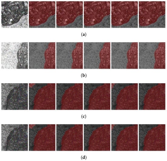
Figure 14.
Comparison of image segmentation module ablation experiment results. Subfigures (a–d) present different representative samples selected from the dataset to demonstrate the module’s effectiveness across various coal–rock scenarios.
Table 4.
Comparison of experimental results of ablation of image segmentation modules.
Replacing the encoder with the Res2Block structure (Group 2) led to improved segmentation accuracy, with only a slight increase in the overall parameter count. The use of a dilated convolution-based multi-channel attention module in Group 3, replacing the intermediate convolutional layer, resulted in better segmentation results and fewer trainable parameters compared to the baseline.
Group 4 replaced the skip connections in the U-Net architecture with a full-scale connectivity structure, which resulted in improved segmentation accuracy at the cost of a marginal increase in parameters. Group 5 integrated all the aforementioned enhancements, achieving the best evaluation metrics among all groups without significantly increasing the parameter count or computational time. This configuration effectively enabled accurate coal–rock image segmentation even under noisy conditions.
In summary, the proposed improved model significantly enhances the segmentation accuracy of coal–rock images while maintaining a low parameter footprint and high computational efficiency.
The multidimensional loss function employed in our model is crucial in guiding effective feature learning and enhancing segmentation precision. By jointly optimizing decomposition consistency, reflectance denoising, and luminance fidelity, the network maintains semantic and structural coherence across all stages of the pipeline. This integrated supervision ensures that the enhanced image remains consistent with its physical and visual properties, thereby improving the quality of features provided to the segmentation module. As a result, the segmentation head benefits from inputs with more uniform brightness, reduced noise, and preserved boundary cues, leading to superior pixel-level classification performance. The improvements in the MIoU and MPA scores observed in Table 4 validate the practical significance of this multidimensional optimization strategy.
5. Practical Significance and Realistic Challenges
The proposed coal–rock recognition model holds substantial practical value in real-world mining applications. Its ability to accurately identify and segment coal and rock regions contributes to improved operational efficiency and enhanced safety. By enabling precise recognition, the model reduces the need for manual intervention, streamlines mining processes, and minimizes the risk of human error. Moreover, integrating the model into intelligent monitoring systems facilitates the real-time analysis of mining activities, thereby supporting data-driven decision-making and advancing the broader objective of intelligent mining [27]. The model’s interpretability further enhances its applicability by providing insight into prediction outcomes, which is particularly valuable in complex scenarios where understanding the rationale behind model decisions is critical.
Nevertheless, deploying the model in real underground mining environments presents several challenges. One of the primary issues is the variability in the environmental conditions in mines. Dynamic lighting environments—ranging from low illumination to high reflection or shadowed areas—can adversely affect input image quality and, consequently, model performance. Additionally, dense dust and particulate matter may obscure key visual features, complicating accurate segmentation. Variations in humidity and temperature can also impact both imaging equipment performance and data quality.
Another critical challenge involves hardware compatibility. Many existing mining systems lack the computational resources necessary to efficiently run deep learning models. This necessitates the development of lightweight model variants or the adoption of edge computing solutions to alleviate dependence on centralized infrastructure. Moreover, the heterogeneity of imaging devices across different mining sites may require additional preprocessing to standardize inputs and maintain consistent performance.
Several strategies can be employed to address these challenges. Enhancing the model’s adaptability to environmental variation is crucial. This may involve further optimizing the multi-scale brightness-enhancement module to accommodate a broader range of lighting conditions and integrating advanced denoising techniques to mitigate dust interference. To improve deployment feasibility, model compression techniques—such as pruning and quantization—can be applied to reduce computational demands. In parallel, edge computing frameworks may be leveraged to enable real-time, localized inference.
Diversifying the training dataset is also essential to improving model generalization. Incorporating data from multiple mining sites with varied geological and environmental characteristics can enhance robustness. Additionally, transfer learning approaches may allow for rapid adaptation to new environments with minimal retraining overhead.
In conclusion, while the proposed model shows significant promise for enhancing coal–rock recognition in underground mining, its practical implementation requires challenges related to environmental variability, computational constraints, and dataset diversity to be overcome. Addressing these issues through targeted model optimization and adaptive deployment strategies will be key to realizing the full potential of this technology in operational settings.
6. Summary and Prospect
6.1. Summary
This paper proposed an underground coal–rock image recognition method based on the joint migration and enhancement of multidimensional full-scale visual features. The acquisition of dependencies between long distances using the NR-Transformer structure denoises the image and the multi-scale module enhances the luminance preventing local over- or underexposure. By incorporating multi-channel attention mechanisms and full-scale connection strategies, the model achieves deeper semantic mining of coal–rock characteristics while maintaining equilibrium between layer depth and gradient backpropagation. The proposed coal–rock image recognition method mainly enhances the brightness of the coal–rock image but has limited enhancement effects on other low-quality features, so it should be combined with other methods in the future for full enhancement of the coal–rock image.
6.2. Future Research Directions
Although the proposed model has shown strong performance in coal–rock recognition tasks, several important limitations and deployment challenges remain. Addressing these issues will be the focus of our future work to enhance the model’s reliability and industrial applicability.
First, the model’s architecture integrates multi-scale luminance enhancement, residual attention, and Transformer-based modules, which collectively increase its depth and parameter count. While this design improves recognition accuracy under complex visual conditions, it also raises the risk of overfitting, particularly when applied to limited-scale datasets. To mitigate this, we plan to explore model simplification techniques such as pruning, quantization, and knowledge distillation, while investigating uncertainty-aware learning to improve robustness on ambiguous inputs.
Second, although preliminary measurements suggest that the model can process 384 × 384 images within 82 ms on mid-range GPUs, practical mining deployments often operate under strict hardware constraints. Therefore, we are actively developing lightweight variants of the model tailored for edge deployment using embedded GPU platforms such as NVIDIA Jetson Xavier NX. This will allow real-time inference on mobile or autonomous inspection systems in underground environments.
Third, the current model is trained on coal–rock datasets with relatively stable geological textures. In real-world operations, the model may encounter unseen rock types, variable mineral compositions, or abrupt structural anomalies. To address this, we will incorporate domain generalization and transfer learning methods to enhance adaptability across different mines and regions.
Fourth, to systematically evaluate model performance under controlled variations, we are in the process of constructing an underground coal–rock simulation environment. This setup is designed to replicate multiple mining conditions, including different coal–rock material compositions, lighting intensities, dust concentrations, and surface reflectance. It will support the development of a more realistic dataset and provide a valuable platform for testing generalization, robustness, and sensor integration under extreme conditions.
Finally, the current framework primarily relies on visual information, which may degrade under conditions such as occlusion, heavy dust, or poor lighting. Therefore, future research will also explore multi-modal learning strategies by integrating complementary sensing data (e.g., acoustic, thermal, or LiDAR) to achieve more robust and comprehensive underground scene understanding.
Author Contributions
Methodology, B.J.; conceptualization, C.S.; data curation, S.Q.; software, W.W.; writing—original draft, Y.W.; validation, Y.L.; writing—review and editing, Z.W.; resources, D.S. All authors have read and agreed to the published version of the manuscript.
Funding
This work was supported by the Fund for the National Key Research and Development Program of China [2022YFB3205804], by the Fund for the National Key Research and Development Program of China [2022YFC2905700], and by the Fund for the Fundamental Research Programs of Shanxi Province [202203021221106]. This paper is supported by the opening project of State Key Laboratory of Coal Mine Disaster Dynamics and Control, Chongqing University, Chongqing 400044, China. The opening project number is 2011DA105287-FW202408.
Institutional Review Board Statement
Not applicable.
Informed Consent Statement
Not applicable.
Data Availability Statement
The data presented in this study are available on request from the corresponding author. The data are not publicly available due to ongoing related research and confidentiality agreements with industrial partners involved in the data collection process.
Acknowledgments
The authors would like to thank Chuanmeng Sun, School of Electrical and Control Engineering, North University of China, and Yong Li, Chongqing University, who provided resources and financial support for this research.
Conflicts of Interest
The authors declare no conflicts of interest.
References
- Xu, S.; Jiang, W.; Liu, Q.; Wang, H.; Zhang, J.; Li, J. Coal-rock interface real-time recognition based on the improved YOLO detection and bilateral segmentation network. Undergr. Space 2025, 10, 233–245. [Google Scholar] [CrossRef]
- Li, X.; Wang, X.; Chen, J.; Zhao, H. The semantic segmentation method of coal rock image based on resnest. In Proceedings of the 2023 4th International Seminar on Artificial Intelligence, Networking and Information Technology (AINIT), Qingdao, China, 16–18 June 2023; pp. 740–744. [Google Scholar]
- Liu, H.; Zhang, Y.; Li, Q.; Chen, Z. Automatic Coal and Rock Interface Recognition Based on Dual-Branch Fusion Network. IEEE Trans. Geosci. Remote Sens. 2024, 62, 9850–9863. [Google Scholar]
- Zhou, H.; Yang, X. Fusion of Vibration and Image Signals for Coal-Rock Interface Recognition. Sensors 2024, 24, 101. [Google Scholar] [CrossRef]
- Song, C.; Xu, C.; Tian, M.; Chen, R. Coal-rock interface image segmentation based on u 2 net model with coordinate attention. In Proceedings of the 2023 6th International Conference on Intelligent Autonomous Systems (ICoIAS), Shanghai, China, 22–24 September 2023; pp. 28–34. [Google Scholar]
- Hua, T.; Xing, C.; Zhao, L. Recognition of coal rock and positioning measurement of coal seam based on faster r-cnn. Min. Process. Equip. 2019, 47, 4–9. [Google Scholar]
- Zhang, B.; Su, X.; Duan, Z.; Chang, L.; Wang, F. Application of yolov2 in intelligent recognition and location of coal and rock. J. Min. Strat. Control Eng. 2020, 2, 94–101. [Google Scholar]
- Si, L.; Wang, Z.; Xiong, X.; Tan, C. Coal-rock recognition method of fully-mechanized coal mining face based on improved u-net network model. J. China Coal Soc. 2021, 46, 578–589. [Google Scholar]
- Si, L.; Xiong, X.; Wang, Z.; Tan, C. A deep convolutional neural network model for intelligent discrimination between coal and rocks in coal mining face. Math. Probl. Eng. 2020, 2020, 2616510. [Google Scholar] [CrossRef]
- Wang, X.; Gao, F.; Chen, J.; Hao, P.; Jing, Z. Generative adversarial networks based sample generation of coal and rock images. J. China Coal Soc. 2021, 46, 3066–3078. [Google Scholar]
- Gao, F.; Yin, X.; Liu, Q.; Huang, X.; Bo, Y.; Zhang, Q.; Wang, X. Coalrock image recognition method for mining and heading face based on spatial pyramid pooling structure. J. China Coal Soc. 2021, 46, 4088–4102. [Google Scholar]
- Yan, Z.; Wang, H.; Geng, Y. Coal-rock interface image recognition method based on improved deeplabv3+ and transfer learning. Coal Sci. Technol. 2023, 51, 328–338. [Google Scholar]
- Sun, C.; Wang, Y.; Wang, C.; Xu, R.; Li, X. Coal-rock interface identification method based on improved yolov3 and cubic spline interpolation. J. Min. Strat. Control Eng. 2022, 4, 016522. [Google Scholar]
- Sun, C.; Li, X.; Chen, J.; Wu, Z.; Li, Y. Coal-rock image recognition method for complex and harsh environment in coal mine using deep learning models. IEEE Access 2023, 11, 80794–80805. [Google Scholar]
- Sun, C.; Xu, R.; Wang, C.; Ma, T.; Chen, J. Coal rock image recognition method based on improved clbp and receptive field theory. Deep Undergr. Sci. Eng. 2022, 1, 165–173. [Google Scholar] [CrossRef]
- Wang, C. Low-Light Coal-Rock Image Enhancement Based on Hybrid Algorithm and Human-Simulated Intelligent Control of Shearer Mining Height. Master’s Thesis, North University of China, Taiyuan, China, 2022. [Google Scholar]
- Wang, Y. Coal-Rock Boundary Identification Based on Improved Yolov3 and Research on Human-Simulating Intelligentcontrol of Mining Height. Master’s Thesis, North University of China, Taiyuan, China, 2021. [Google Scholar]
- Wang, F.; Liu, T. Coal-rock interface recognition based on CNN with attention mechanism. Tunn. Undergr. Space Technol. 2023, 134, 105027. [Google Scholar]
- You, K.; Liu, H. Intelligent deployment solution for tabling adapting deep learning. IEEE Access 2023, 11, 22201–22208. [Google Scholar]
- You, K.; Liu, H. Feature detection of mineral zoning in spiral slope flow under complex conditions based on improved yolov5 algorithm. Phys. Scr. 2023, 99, 016001. [Google Scholar]
- Liu, Y.; Ma, C. Research on Coal-Rock Interface Recognition in Intelligent Shearer. Int. J. Min. Sci. Technol. 2023, 33, 85–92. [Google Scholar]
- Zhao, H.; Shi, J.; Qi, X.; Wang, X.; Jia, J. Pyramid scene parsing network. In Proceedings of the IEEE Conference on Computer Vision and Pattern Recognition (CVPR), Honolulu, HI, USA, 21–26 July 2017; pp. 2881–2890. [Google Scholar]
- Wei, C.; Wang, W.; Yang, W.; Liu, J. Deep retinex decomposition for low-light enhancement. arXiv 2018, arXiv:1808.04560. [Google Scholar]
- Zhu, A.; Zhang, L.; Shen, Y.; Ma, Y.; Zhao, S.; Zhou, Y. Zero-shot restoration of underexposed images via robust retinex decomposition. In Proceedings of the 2020 IEEE International Conference on Multimedia and Expo (ICME), London, UK, 6–10 July 2020; pp. 1–6. [Google Scholar]
- Chen, L.-C.; Papandreou, G.; Kokkinos, I.; Murphy, K.; Yuille, A.L. Deeplab: Semantic image segmentation with deep convolutional nets, atrous convolution, and fully connected crfs. IEEE Trans. Pattern Anal. 2017, 40, 834–848. [Google Scholar] [CrossRef]
- Badrinarayanan, V.; Kendall, A.; Cipolla, R. Segnet: A deep convolutional encoder-decoder architecture for image segmentation. IEEE Trans. Pattern Anal. 2017, 39, 2481–2495. [Google Scholar] [CrossRef]
- You, K.; Wen, C.; Liu, H. Research on intelligent implementation of the beneficiation process of shaking table. Miner. Eng. 2023, 199, 108108. [Google Scholar]
Disclaimer/Publisher’s Note: The statements, opinions and data contained in all publications are solely those of the individual author(s) and contributor(s) and not of MDPI and/or the editor(s). MDPI and/or the editor(s) disclaim responsibility for any injury to people or property resulting from any ideas, methods, instructions or products referred to in the content. |
© 2025 by the authors. Licensee MDPI, Basel, Switzerland. This article is an open access article distributed under the terms and conditions of the Creative Commons Attribution (CC BY) license (https://creativecommons.org/licenses/by/4.0/).