Article

Investigation of Hybrid Tooth Profiles for Robotic Drives Based on IH Tooth Profiles and Cycloidal Curves

1
Department of Mechanical Engineering, Chung-Ang University, Seoul 06974, Republic of Korea
2
Bucheon Techno Park 401-402, 655 Pyeongcheon-ro, Wonmi-gu, Bucheon-si 14502, Gyeonggi-do, Republic of Korea
3
Department of Mechanical & Automotive Engineering, Hanyang Cyber University, Seoul 04763, Republic of Korea
*
Authors to whom correspondence should be addressed.
Appl. Sci. 2025, 15(10), 5389; https://doi.org/10.3390/app15105389
Submission received: 9 April 2025 / Revised: 7 May 2025 / Accepted: 9 May 2025 / Published: 12 May 2025

Abstract

:
Recently, with policies aimed at strengthening domestic manufacturing and technological innovation, the robotics industry has been growing rapidly, and its applications are expanding across various industrial fields. Accordingly, the importance of high-performance speed reducers with flexibility and precision is gradually increasing. The tooth profiles used in conventional harmonic reducers have structural limitations, such as meshing discontinuity, restrictions on the radius of curvature of the tooth base, and distortion of the contact trajectory, especially when the number of teeth is small. These problems limit the design freedom of the reducer and make it difficult to secure contact stability and durability under precision driving conditions. To solve these problems, this paper proposes a new tooth profile design equation, the IH (Involute Harmonic) tooth profiles and the HTPs (Hybrid Tooth Profiles), using the cycloid curve to overcome the structural limitations of the conventional harmonic tooth profile, which is difficult to design under small-tooth-number conditions, and to enable tooth design without restrictions on the number of teeth. HTP tooth profile is a new gear tooth profile design method that utilizes IH tooth profile and cycloid curve to optimize the meshing characteristics of gears. A tooth profile design tool based on the HTP equation was developed using Python 3.13.3. The tool’s effectiveness was validated through simulations assessing tooth meshing and interference. Using the tool, an R21_z3 reducer with a single-stage high reduction ratio was designed to evaluate practical applicability. A prototype was fabricated using 3D printing with PLA material, and experimental testing confirmed the absence of meshing or interference issues, consistent with simulation results. Through this study, we verified the usefulness of the HTP tooth profile design formula and design tool using the IH tooth profile and cycloid curve, and it is expected that the proposed HTP tooth profile can be utilized as a tooth profile applicable to various reducer designs.

1. Introduction

With rapid advancements in the industrial landscape and innovations in science and technology, increasing emphasis is being placed on achieving customized production through human–robot collaboration and on establishing sustainable manufacturing systems. These shifting demands are significantly influencing the design and performance of both industrial and service robots, particularly highlighting the importance of high-performance reducers to meet the precision and flexibility required in modern manufacturing environments.
As user demands for high-performance reducers diversify, tooth profile design is gaining attention as a critical factor influencing reducer efficiency and performance. Representative tooth profiles include the cycloidal and involute profiles. The cycloidal profile, characterized by isochronism and the brachistochrone curve, contributes to stable power transmission and reduced energy loss, enabling high efficiency and low friction. The involute profile has revolutionized gear design with its ability to maintain a constant velocity ratio and ease of manufacturing. Ongoing research, supported by technological advances and innovation in related fields such as motors and controllers, continues to enhance the performance of robotic reducer systems.
The cycloidal tooth profile offers a high reduction ratio and durability and is characterized by excellent torque transmission efficiency and low backlash. Its structure, in which multiple teeth engage simultaneously, averages out errors and is widely evaluated as suitable for high-precision reducers. Based on these advantages, theoretical, technical, and applied research is actively being conducted. Nam, Won-Ki, and Se-Hoon Oh proposed a new trapezoidal tooth profile reducer for robot manipulators, aiming to simplify the design and optimize performance through differentiation from conventional profiles. They validated the effectiveness of the proposed profile through mechanical analysis and testing [1]. Ren et al. studied tooth profile modification to improve the performance of cycloidal reducers, analyzing the effects on load capacity, noise reduction, vibration mitigation, and transmission accuracy. Their study demonstrates that tooth profile modification is a key factor in optimizing reducer design and performance [2]. Jang et al. analyzed the design and dynamic characteristics of a modified cycloidal reducer applying an epitrochoidal tooth profile, demonstrating that the new profile improves efficiency and stability [3]. Li et al. proposed a new method for modifying cycloidal gear tooth profiles used in precision reducers for robots. By developing a mathematical model that considers pressure angle distribution and backlash, they enhanced meshing characteristics and power transmission performance, thereby improving design flexibility and transmission accuracy [4]. Thai et al. designed and manufactured an internal noncircular gear based on an improved cycloidal profile to overcome the limitations of conventional profiles and optimize motion efficiency and gear performance [5]. Overall, reducers using cycloidal tooth profiles offer excellent characteristics, including compact design, low backlash, high accuracy, and high efficiency [3,6].
Due to its structural characteristics, the harmonic drive—initially called the “strain wave gearing system”—comprises a wave generator, a flexspline, and a circular spline. It is known for its high reduction ratio, lightweight design, and high efficiency [7,8,9,10]. These advantages have led to its widespread adoption in aerospace applications such as solar panel deployment mechanisms, antenna pointing systems, and planetary rover wheel drives, as well as in industrial robots [11,12]. To improve the performance of harmonic drives, extensive research on tooth profile design is ongoing. Ishikawa conducted a geometric analysis of the meshing characteristics between the flexspline and circular spline, demonstrating that continuous contact during meshing can be achieved by designing the tooth profile based on the flexspline’s deformation trajectory. This approach improves both efficiency and fatigue life [13,14]. Kiyosawa proposed a new tooth profile to overcome conventional limitations, improving fatigue strength and torque transmission. The design maintains high stiffness even under low torque, thus enhancing durability and extending gear life [15]. Kondo and Takada analyzed the kinematic and geometric characteristics of tooth meshing, treating the flexspline as a rigid body. They defined the tooth profile based on gear mechanism theory, assuming constant gear spacing at the neutral line where common normals intersect at the pitch point [16]. Maiti addressed the kinematic limitations of non-involute profiles in existing harmonic drives and developed a new wave generator using an involute profile. This approach eliminated tooth interference and enabled precise gear motion [17]. Cao, et al. applied a double-arc tooth profile to the flexspline and circular spline, and, through finite element analysis, confirmed superior durability and meshing characteristics compared to conventional profiles [18]. Yu and Ting validated a new geometric tooth profile model via Ansys Workbench simulations, using explicit dynamic analysis to predict elastic and nonlinear behavior. The design’s accuracy was confirmed through comparison with theoretical and experimental results [19]. Li, et al. analyzed flexspline deformation based on ring theory and introduced a tooth profile coordinate adjustment method. This approach prevents undercutting and improves meshing reliability [20]. Xie et al. designed a new tooth profile combining hypocycloidal and epicycloidal curves, enabling more simultaneous tooth engagement and offering a simpler mathematical formulation. Their design was validated through finite element analysis and prototype testing [21]. Huang et al. introduced a high-contact-ratio two-dimensional tooth profile based on central engagement. By leveraging the kinematic relationship between the neutral layer and pitch circle of the flexspline and circular spline, they enabled continuous engagement and zero backlash. The design was verified through mathematical analysis and kinematic simulations [22].
In this paper, the tooth profiles used in conventional harmonic reducers have structural limitations such as meshing discontinuity, restrictions on the radius of curvature of the tooth base, and distortion of the contact trajectory, especially when the number of teeth is small. These problems limit the design freedom of the reducer and make it difficult to secure contact stability and durability under precision driving conditions. To solve these problems, this paper proposes a new tooth profile design equation, the IH (Involute Harmonic) tooth profiles and the HTPs (Hybrid Tooth Profiles), using the cycloid curve to overcome the structural limitations of the conventional harmonic tooth profile, which is difficult to design under small-tooth-number conditions, and to enable tooth design without restrictions on the number of teeth. Theoretical equations for the HTP design were derived, and the x and y trajectories for each profile were plotted using key parameters to illustrate differences from previously studied profiles. The proposed equation is a generalized design formula that allows tooth profiles to be generated without constraints on the number of teeth. Additionally, a Python-based HTP tooth profile design program was developed, enabling real-time visualization of the tooth meshing state through simulation. To evaluate the field applicability of the proposed profile, an R21_z3 single-stage high-reduction-ratio reducer was designed, and its strength and meshing condition were verified through static analysis in Ansys. Finally, the proposed HTP tooth profile equation was verified through a simple prototype by confirming the absence of interference with the actual tooth meshing state.

2. Tooth Profile Characteristics of Harmonic Reducer

The representative tooth profiles used in harmonic reducers are the involute tooth profile and the modified involute tooth profile. In the case of harmonic drive systems, these profiles are categorized as the CS type, which uses a standard involute profile, and the IH type, which adopts a modified involute profile. Figure 1 illustrates the IH tooth profile developed and applied by harmonic drive systems. This profile is generated by combining convex and concave curves: the addendum surface is formed from a convex curve, the dedendum surface from a concave curve, and the transition between the two is a straight line [23].
The application of the IH tooth profile has led to improvements in fatigue strength and torsional stiffness compared to conventional involute profiles. In particular, the R-type profile is reported to enhance torsional stiffness in low-torque regions. This profile brings the flexspline and circular spline into contact from the initial stage of meshing, increasing the total number of meshing teeth by approximately 10–30% compared to the standard involute profile. Additionally, the use of a wide, circular dedendum reduces stress concentration, allowing for a thinner and shorter flexspline. Since input torque is proportional to the deformation of the flexspline, a larger deformation requires an increased inner diameter of the flexspline and, hence, greater deformation of the inner bearing. This deformation is closely linked to the offset coefficient, which in the case of harmonic drive, is approximately 1. A comparative summary of the tooth profile curve, meshing ratio, efficiency, and transmission error for various profiles is presented in Table 1. As shown, both the cycloidal and composite IH tooth profiles exhibit higher contact ratios than the involute profile. However, this increased meshing can result in slightly lower efficiency. Despite this, the IH profile offers improved torque transmission and reduced root stress due to its geometry [24].

3. HTP Tooth Profile Design Using IH Tooth Profile and Cycloidal Curve

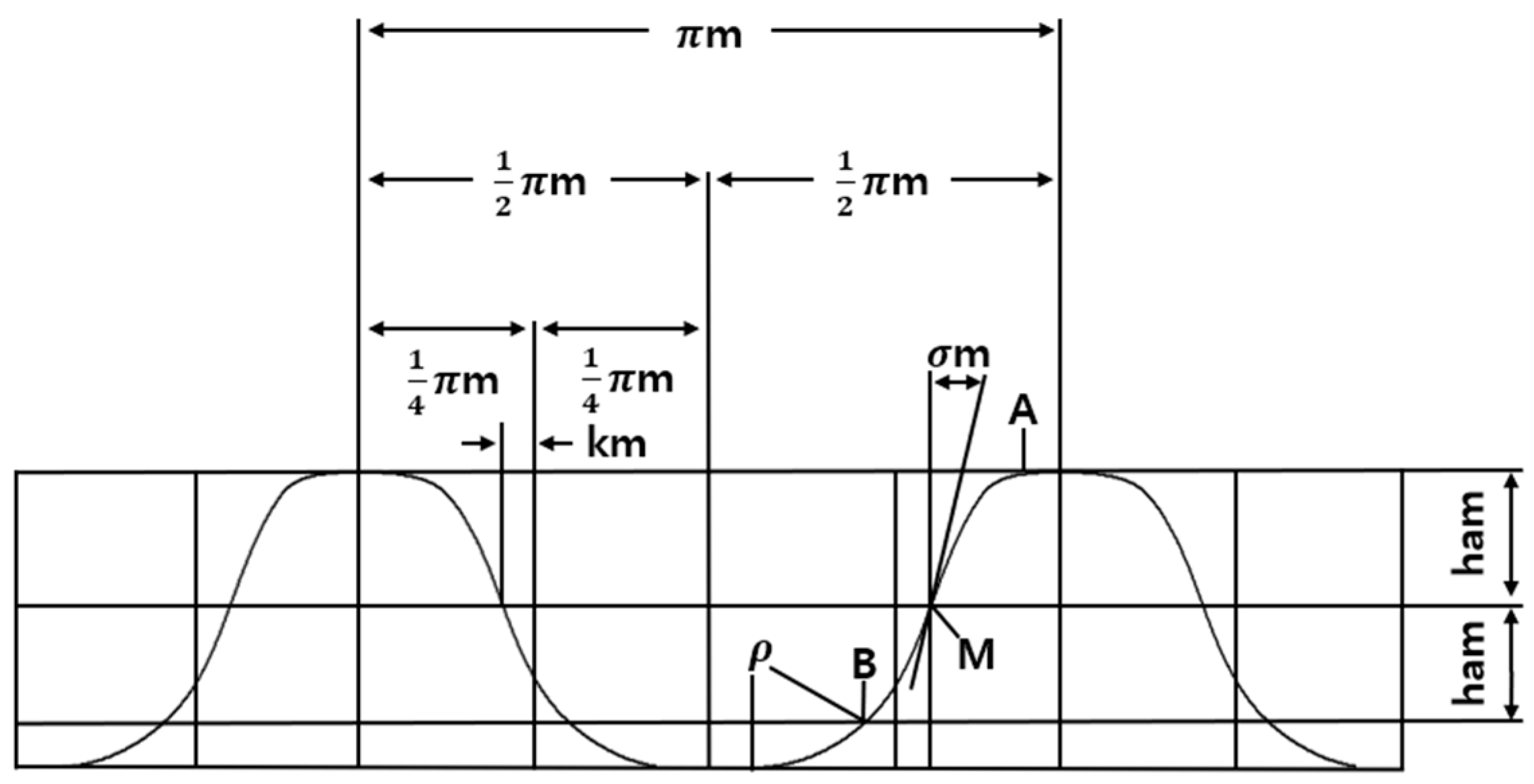
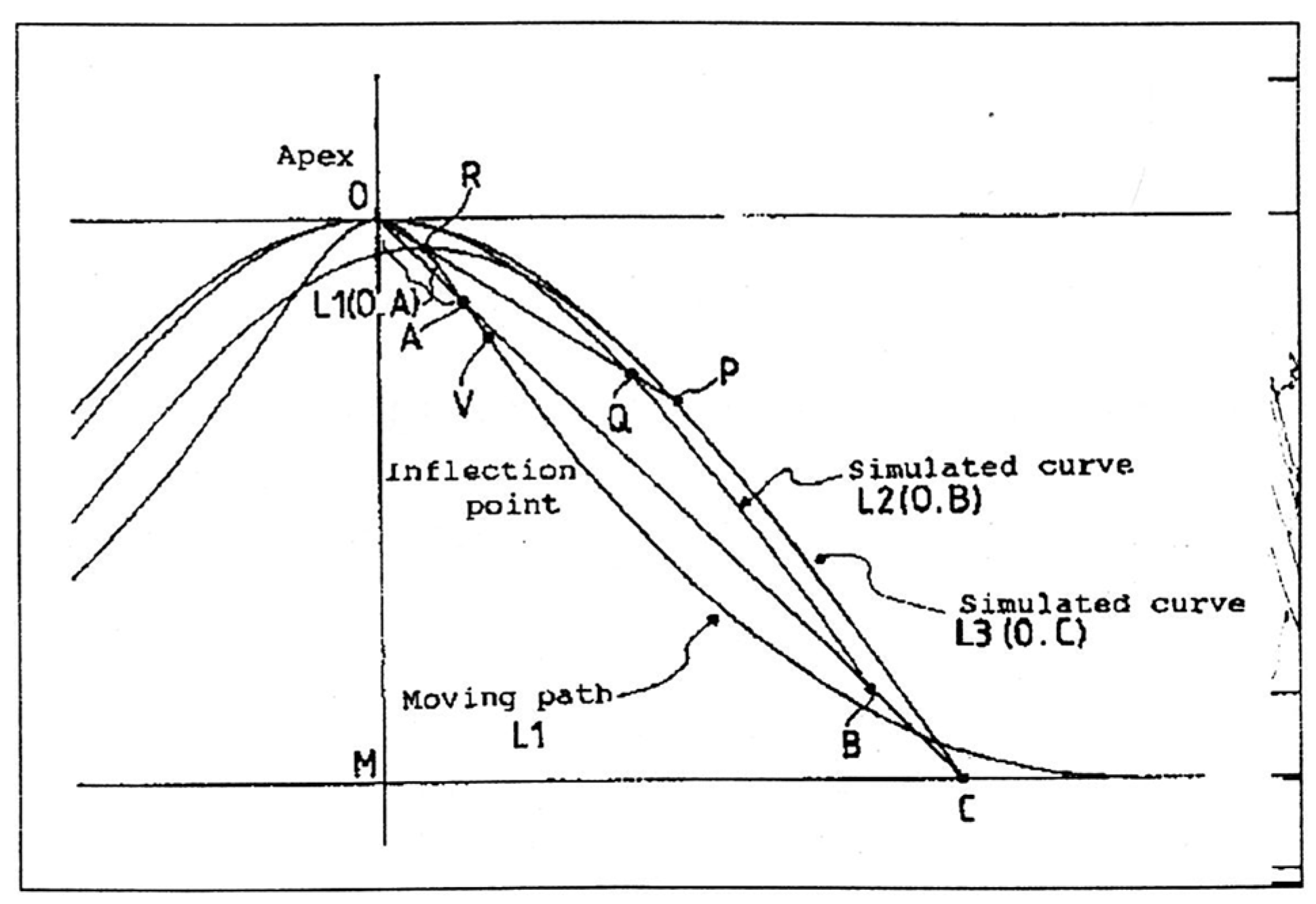
3.1. IH Tooth Profile Theory

The harmonic reducer achieves high reduction ratios and precision by using a structure in which the wave generator deforms the external gear (flexspline), causing it to engage with the internal gear (circular spline). When the number of teeth is large, the tooth profile can be approximated as straight; however, when the number of teeth is small, problems such as increased friction and backlash may occur. To address these issues, the IH tooth profile models the trajectory of a point p ϕ ,   q ϕ on the flexspline as a function of the wave generator’s rotation angle, ϕ , and establishes continuous meshing conditions between the internal and external gears based on this trajectory. This trajectory-based design concept is visually represented in Figure 2 [25].
When the rotation angle, ϕ , of the wave generator in the harmonic reducer is 0, the motion trajectory of the outer tooth gear can be defined as a curve, l , based on the engagement position between the inner and outer tooth gears, as ϕ varies from 0 to π / 2 . This curve, l , is described by Equation (1) and corresponds to L1. In IH tooth profile design, only a portion of this curve may be used, and in such cases, the range of ϕ may be narrower than 0 ϕ π / 2 .
x l y l = p ϕ q ϕ ,   0 ϕ π 2
Among the endpoints of curve l, point A is defined at ϕ = 0 , point B at ϕ = π / 2 , and point C as the midpoint between A and B. The addendum profile of the internal tooth gear can be defined using a similar curve, obtained by scaling curve l by a factor λ   ( 0 < λ < 1 ) about point B. This scaled curve is represented by Equation (2) and corresponds to L2.
x c a y c a = λ p θ + 1 λ p π 2 λ q θ + 1 λ q π 2 ,   0 θ π 2
By scaling curve l by (1 − λ) about point B to obtain a homothetic curve and then rotating it 180° about point C, the addendum tooth profile of the external tooth gear can be derived. This profile is expressed in Equation (3), corresponding to L3.
x f a y f a = 1 λ p θ + p 0 + 1 λ p π 2 1 λ q θ + q 0 + 1 λ q π 2 ,   0 θ π 2
Since the internal and external tooth gears of the harmonic reducer have a large number of teeth, they can be approximated as racks with infinite teeth. Under this rack approximation, the inclination of the tooth vanishes. Thus, as the apex of the external addendum tooth profile (Equation (3)) moves along the trajectory defined by Equation (1), the group of addendum tooth profiles formed can be expressed by Equation (4):
x f a g y f a g = x f a ϕ x f a π 2 y f a ϕ y f a π 2 + x 1 y 1 = 1 λ p θ + p 0 + 1 λ p π 2 + p ϕ p 0 1 λ q θ + q 0 + 1 λ q π 2 + q ϕ q 0
The envelope of the external addendum tooth profiles forms the meshing points. The condition for envelope formation is that the Jacobian of Equation (4) becomes zero, expressed as follows:
x f a g ϕ y f a g θ x f a g θ y f a g ϕ = 0
Solving Equation (5) yields the following result:
1 λ p ϕ ϕ q θ θ + 1 λ p θ θ q ϕ ϕ = 0
This condition always holds when ϕ = θ . Therefore, by setting ϕ = θ into Equation (4), the envelope of the external addendum tooth profile group is obtained as follows [26]:
x f a g ϕ = 0 y f a g ϕ = 0 = λ p θ + 1 λ p π 2 λ q θ + 1 λ q π 2 ,   0 θ π 2

3.2. Cycloid Curve Theory

A cycloidal curve is generated by a circle rolling along a straight line and serves as a key element in efficient gear meshing. An extension of this concept is the epitrochoid curve, which represents the trajectory formed when a circle rolls externally around a fixed circle. Epitrochoid curves are advantageous in gear design due to their ability to increase the proportion of rolling contact, reduce friction on the tooth surface, and enhance durability. As a result, smooth meshing can be achieved even in gear systems with a low tooth count. Furthermore, by introducing an offset or applying ± translational motion, optimized meshing can be maintained despite having fewer teeth than conventional cycloidal curves. In other words, modifying the epitrochoid curve allows the design of low-tooth-count gears while preserving efficient meshing characteristics. The general mathematical expression for an epitrochoid curve is given by the following parametric equations:
x θ = R + r cos θ d cos R + r r θ
y θ = R + r sin θ d sin R + r r θ
where R is the radius of the fixed circle, r is the radius of the rolling circle, d is the distance from the center of the rolling circle to the point generating the curve, and θ is the rotation angle of the rolling circle. This epitrochoid formulation extends the traditional cycloidal curve, enabling broader applicability in gear design and improving meshing performance—especially in low-tooth-count configurations.
To analyze the meshing characteristics using cycloidal and epitrochoid curves, the following parametric equations can be used:
x t = r z + 1 cos t d cos z + 1 t
y t = r z + 1 sin t d sin z + 1 t
where r is the radius of the rolling circle, z is the number of gear teeth, d is the distance from the center of the rolling circle to the reference point of the tooth profile, and t is the parameter ( 0 t 2 π ). At the meshing pitch point, Equation (10) can be rearranged through a coordinate transformation as follows:
x t r z = r z cos t r z + r cos t d cos z + 1 t
The derivative with respect to the x-axis is expressed as follows:
x t = r cos t d cos z + 1 t
By applying a coordinate transformation to Equations (12) and (13), the equations can be rewritten with the x and y coordinates switched, yielding the following:
x = r z + 1 sin t d sin z + 1 t
y = r z cos t r z + r cos t d cos z + 1 t
Substituting θ = z + 1 t leads to the following expressions:
x = r z + 1 sin θ z + 1 d sin θ
y = r z + 1 cos θ z + 1 r z d cos θ

3.3. HTP Tooth Profile Design Theory

The HTP tooth profile is a novel gear tooth design method that enhances meshing characteristics by incorporating the IH tooth profile and the cycloidal curve. In conventional gear systems, achieving a high contact ratio and continuous engagement has been a key objective. The IH tooth profile was introduced to address this, improving continuous engagement by increasing the contact ratio compared to the traditional involute profile. However, the IH profile has limitations in enabling optimal rolling contact for low-tooth-count gears due to its fixed-envelope-based design. To overcome this, the HTP tooth profile builds upon the fundamental concept of the IH profile while integrating a modified cycloidal curve based on the epitrochoid to optimize contact characteristics. The HTP tooth profile maintains the envelope-based structure of the conventional IH tooth profile, but it adopts a hybrid design by applying a cycloidal curve based on the epitrochoid to more precisely reproduce the actual contact trajectory in the external tooth addendum region. The IH profile simplifies gear motion into a linear trajectory through rack approximation, providing a high contact ratio. However, the actual motion of external gears is rotational based on a fixed center, resulting in nonlinear changes in the position of the actual contact point and the tangential velocity vector. To account for this nonlinearity, this study substitutes an epitrochoid curve in a specific section of the external addendum region of the IH profile. In this process, scaling factors α and β are applied in the X and Y directions, respectively, to finely adjust the geometric shape and meshing characteristics. The overall tooth profile is designed to maintain the envelope condition of the IH profile while being continuously connected with the epitrochoid trajectory. The cycloidal curve (based on the epitrochoid) was adopted on the following theoretical grounds. First, this curve has characteristics that induce pure rolling contact, which can minimize friction and wear. Second, as shown in Figure 4, when scaling correction is applied, it exhibits a shape almost identical to the ideal meshing trajectory, and compared to the existing IH and harmonic tooth profiles, it provides a more precise approximation. Furthermore, Figures 6–8 confirm that the HTP profile maintains conformity with the ideal trajectory even under low-tooth-count gear conditions, demonstrating that this design choice offers higher structural accuracy and consistent design compared to conventional profiles. Through this, the proposed method offers the potential to optimize rolling contact in traditional gear design, thereby reducing friction, enhancing durability, and achieving high transmission efficiency. It is particularly expected to be a suitable design approach for high-efficiency mechanical systems such as precision reducers and robotic gear systems.
The HTP tooth profile design equations are derived from Equations (1)–(7) of the conventional IH tooth profile. The IH tooth profile defines a rack-shaped curve formed geometrically by specifying the two endpoints (points A and B) and the midpoint (point C). At this point, λ is used as a displacement coefficient and serves as a parameter to adjust the overall position and shape of the tooth profile curve. By applying this coefficient, the shapes of the addendum and flank regions are specified, and the contact conditions are controlled so that the meshing is not interrupted. Furthermore, by additionally introducing scaling factors such as α for the X-coordinate and β for the Y-coordinate, the root width, curvature radius, and tooth thickness can be designed more flexibly. To newly construct the external addendum, the following transformation is performed. Taking point B as the center of similarity, the entire curve l is scaled down by a factor of 1 λ , and this is referred to as the similarity curve. By setting point C as the center of rotation, the similarity curve is rotated by 180° to obtain the second curve. Up to this step, the concept used in the IH tooth profile is applied as it is when λ is given. By multiplying only the X-coordinates of the second curve by α , the third curve corresponding to Equation (18) can be defined. This curve becomes an important feature that serves as the new external addendum tooth profile. θ is a new parameter representing the tooth profile shape, and it is used separately from ϕ in the IH tooth profile. By adjusting the values of α and β , the designer can modify the tooth thickness, radius of curvature, and contact distribution as intended.
x f c y f c = α 1 λ p θ + p 0 + 1 λ p π 2 1 λ q θ + q 0 + 1 λ q π 2 ,   0 θ π 2
By scaling only the Y-coordinate using factor β, the fourth curve is defined as the external tooth addendum profile in Equation (19):
x f c y f c = 1 λ p θ + p 0 + 1 λ p π 2 β 1 λ q θ + q 0 + 1 λ q π 2 ,   0 θ π 2
By applying the rack approximation from Equation (18), the general form of the external tooth addendum profile group is given by Equation (20), with its envelope condition expressed in Equation (21):
x f c g y f c g = α 1 λ p θ + p 0 + 1 λ p π 2 + p ϕ α p 0 1 λ q θ + q 0 + 1 λ q π 2 + q ϕ q 0
1 λ p ϕ ϕ q θ θ + α 1 λ p θ θ q ϕ ϕ = 0
Since obtaining a simple analytical solution may be difficult, the relationship between φ and θ is typically calculated numerically. Substituting the numerical result into Equation (20) allows for the internal tooth addendum tooth profile to be derived. Similarly, by applying Equation (19), the external tooth addendum tooth profile group can be generalized as shown in Equation (22), with the corresponding envelope condition expressed in Equation (23). By numerically calculating the relationship between ϕ and θ and substituting it into Equation (23), the internal tooth addendum profile is obtained.
x f c g y f c g = 1 λ p θ + p 0 + 1 λ p π 2 + p ϕ p 0 β 1 λ q θ + q 0 + 1 λ q π 2 + q ϕ β q 0
β 1 λ p ϕ ϕ q θ θ + 1 λ p θ θ q ϕ ϕ = 0
The tangential polar coordinates are given by Equation (24) for when the external gear tooth is defined as an elliptical shape instead of a simple circle. If the internal tooth meshing is approximated using rack meshing, then curve l is expressed in the form of Equation (25) [26]:
p = r n + κ m n cos 2 ψ ,   0 ψ 2 π
x l y l = 0.5 m n 2 ϕ κ sin 2 ϕ κ m n cos 2 ϕ ,   0 ϕ π 2
Using the above concepts, the HTP tooth profile design equations can be mathematically defined. To determine the envelope of the external tooth addendum group in the HTP profile, the rack approximation method from the conventional IH tooth profile is applied, based on Equation (4), and expressed as Equation (26):
x c c g θ y c c g θ = x c c 1 θ y c c 1 θ + x l y l = 1 λ p θ + p 0 + 1 λ p π + p ϕ p 0 1 λ q θ + q 0 + 1 λ q π + q ϕ q 0
This method defines the external tooth addendum profile group by incorporating the motion trajectory of curve l , and it is applied similarly to the IH tooth profile. The condition for envelope formation is that the Jacobian determinant equals zero, as also applied in the conventional IH profile. This condition is expressed as follows:
x f c g ϕ y f c g θ x f c g θ y f c g ϕ = 0
Thus, the same envelope condition applies to the HTP tooth profile. In the HTP design, the envelope-forming partial differential condition retains the same form as in Equation (6):
1 λ p ϕ ϕ q θ θ + 1 λ p θ θ q ϕ ϕ = 0
This equation is applied with the same logic in the HTP tooth profile and is consistent with the basic envelope formation condition of the IH profile.
To define the initial meshing position in the HTP design, Equation (7) is directly used and expressed as follows:
x f c g ϕ = 0 y f c g ϕ = 0 = λ p θ + 1 λ p π λ q θ + 1 λ q π = 0.5 m n ( λ ( θ κ sin θ ) + 1 λ π ) λ q θ + 1 λ q π
This condition clearly defines the initial point forming the envelope.
In the HTP profile, α-scaling is applied along the X-axis to allow for a more flexible design compared to the IH profile. This modification, building on Equation (20), expands π/2 to π and incorporates X-axis deformation, as shown in Equation (30):
x c c y c c = α 1 λ p θ + p 0 + 1 λ p π + p ϕ α p 0 1 λ q θ + q 0 + 1 λ q π + q ϕ q 0
This enhances design flexibility and enables broader shape control of the external tooth. The envelope condition is updated accordingly:
1 λ p ϕ ϕ q θ θ + α 1 λ p θ θ q ϕ ϕ = 0
Similarly, by using Equation (22), β scaling is applied in the Y-axis direction with an expansion of π / 2 to π to further widen the design scope:
x c c y c c = 1 λ p θ + p 0 + 1 λ p π + p ϕ p 0 β 1 λ q θ + q 0 + 1 λ q π + q ϕ β q 0
This provides additional design freedom and more precise adjustment of the external tooth addendum profile. The corresponding envelope condition is as follows:
β 1 λ p ϕ ϕ q θ θ + 1 λ p θ θ q ϕ ϕ = 0
Up to this point, the HTP tooth profile design equations based on the IH tooth profile have been established. However, accurately describing the motion trajectory of the external tooth gear is difficult using only the rack approximation method applied in the IH tooth profile. In the IH model, gear movement is approximated using a linear rack, but in reality, the external tooth gear follows a nonlinear curved path rather than a simple linear motion. To better reflect this behavior, the epitrochoid curve equation was introduced and incorporated into the HTP tooth profile design. In this design, the gear meshing trajectory is defined using the epitrochoid curve to more precisely capture the movement of the external tooth gear. An epitrochoid curve represents the path traced by a point on a small circle as it rolls along the outside of a fixed larger circle. It is mathematically expressed as follows:
x y = R r cos θ + d cos R r r θ R r sin θ d sin R r r θ
where R is the radius of the fixed circle drawn by the center of the external tooth gear, r is the actual rotation radius of the external tooth gear (the radius of the small circle), d is the distance from a specific point (tooth profile generating point) on the external tooth gear, θ is the angle by which the external tooth gear rotates, and R + r r represents the ratio indicating how many times the small circle rotates while making one revolution around the fixed circle. Equation (34) shows the trajectory drawn by a specific point on the gear as the external tooth gear rotates along the fixed circle. This is essential for analyzing the exact movement path of the external tooth gear, and through this, the meshing between the external tooth gear and the internal tooth gear can be more precisely designed. In the HTP tooth profile design, in order to apply the parameters used in general gear design, Equation (34) is transformed using the module, m, and the gear ratio, z.
x y = m z 1 cos θ + κ m cos z 1 θ m z 1 sin θ κ m sin z 1 θ
Through this, the epitrochoid curve was transformed into a form that can be used in the gear meshing system. In other words, it was transformed into a mathematical expression that reflects the physical characteristics of the gear. Equation (36) is a form where the coordinate system has been transformed to be suitable for gear design. That is, it reflects the relative movement trajectory based on the center of the gear:
x y = m z 1 sin θ κ m sin z 1 θ m z 1 cos θ + κ m cos z 1 θ R r
Equation (37) simplifies the parameters by substituting the new variable, t = z 1 θ . Through this, the mathematical expression of the gear meshing can be further simplified, and it enables precise calculation of the movement trajectory of the external tooth gear in the HTP tooth profile:
x y = m z 1 sin t z 1 κ m sin t m z 1 cos t z 1 + κ m cos t m z 1
By applying the small-angle approximation, the complex trigonometric terms were converted into a simple polynomial form and simplified into Equations (38) and (39). In particular, it can provide a more accurate approximation in the region where θ is small.
sin t z 1 t z 1 , cos t z 1 1 1 2 t z 1 2 x y = m z 1 t z 1 κ m sin t m z 1 1 1 2 t z 1 2 + κ m cos t m z 1
x y = m t κ m sin t κ m cos t m 1 2 t 2 z 1
Finally, the tooth profile equation of the external tooth gear based on the epitrochoid curve is organized as follows:
x y = 0.5 m n θ κ sin θ κ m n cos θ m n 1 2 θ 2 z 1

3.4. Analysis of the HTP Tooth Profile and Conventional Tooth Profiles Through Schematic Comparison

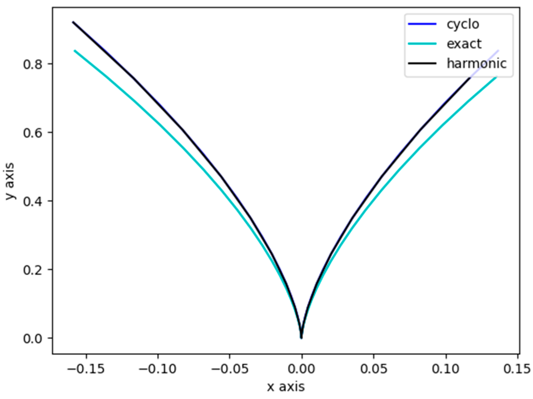
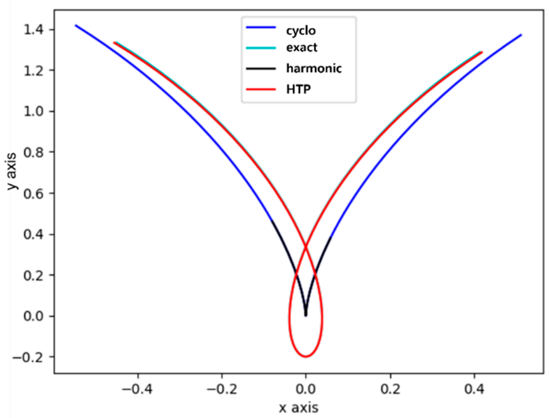
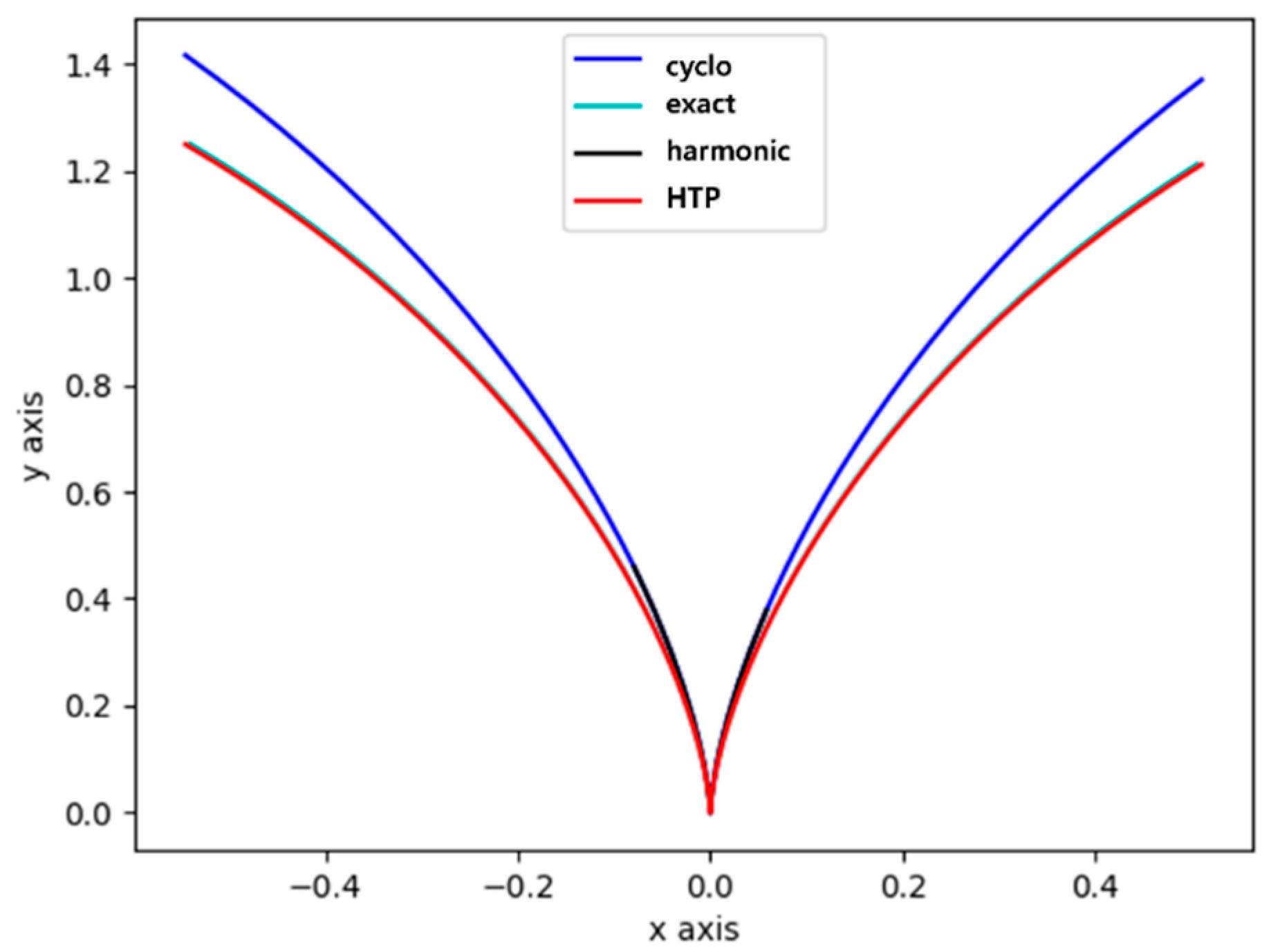
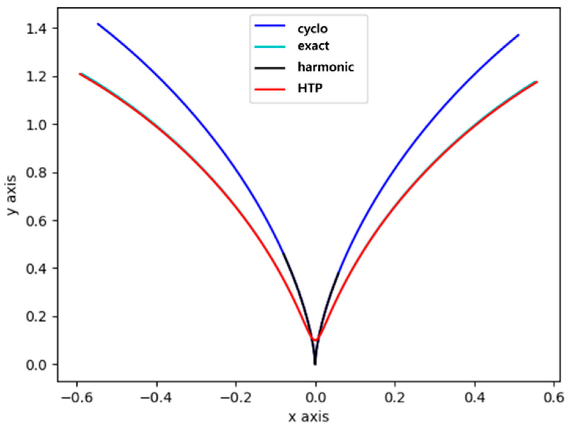
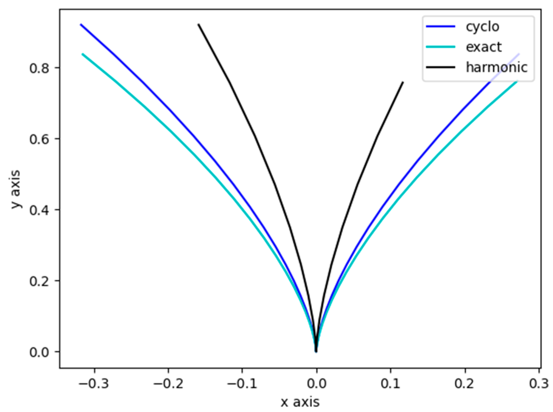
3.4.1. Comparison Among Cycloidal, Harmonic, and Exact Curves

Figure 3 and Figure 4 compare the trajectories of the cycloidal curve (Cycloid), the exact curve (Exact), and the harmonic curve (Harmonic). In Figure 3, the trajectories are shown without scaling the x-axis displacement, clearly revealing differences between the curves. The harmonic curve, designed with actual gear meshing in mind, exhibits noticeable deviations from the exact curve.
In contrast, Figure 4 applies a 1/2 scale adjustment to the x-axis displacement to enable a more direct comparison. After this scale correction, the trajectory of the cycloidal curve closely matches that of the exact curve. This suggests that the cycloidal curve can serve as an appropriate analytical model for exact meshing conditions. The harmonic curve also exhibits a similar trajectory shape, though slight differences remain.
Figure 4. X-Y trajectory for each tooth curve (x-axis scale adjustment).
Applsci 15 05389 g004
As shown in the figures, a consistent deviation is observed between the harmonic (IH) curve and the exact curve. The harmonic curve also differs from the cycloidal curve. These discrepancies reflect the characteristics of the harmonic tooth profile under actual meshing conditions. More precise comparisons may be achieved through additional scale correction.

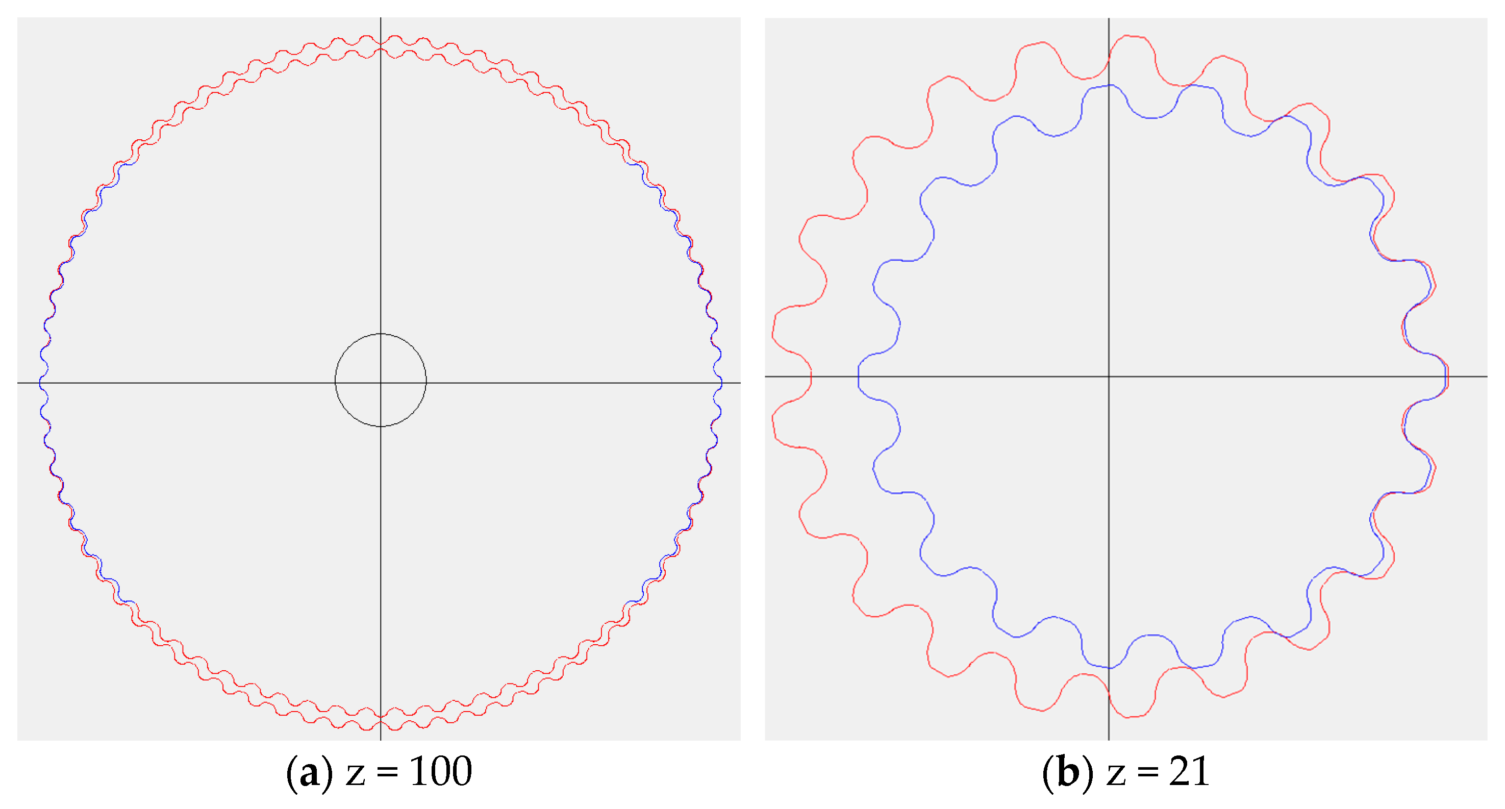
3.4.2. Comparison of Tooth Profile Curve Trajectories According to Tooth Number Change

Figure 5 illustrates the tooth profile trajectories when the number of teeth is 100 (z = 100). In this case, the harmonic IH tooth profile, cycloidal curve, exact curve, and HTP tooth profile show almost identical trajectories. This is because increasing the number of teeth reduces gear meshing errors, resulting in higher agreement with the exact curve. Notably, the HTP tooth profile nearly perfectly aligns with the exact curve, while the harmonic IH and cycloidal curves also follow similar paths. This indicates that the HTP tooth profile can achieve high precision compared to conventional tooth profiles. In other words, when the number of teeth is sufficiently large, there is minimal difference between the conventional IH and HTP tooth profiles, and all curves exhibit similar trajectories.
Figure 5. X-Y trajectory for each tooth curve (z = 100).
Applsci 15 05389 g005
Figure 6 presents the tooth profile trajectories when the number of teeth is reduced to 11 (z = 11). As the number of teeth decreases, the harmonic IH tooth profile begins to diverge from the exact curve, while the HTP tooth profile still closely follows it. This demonstrates that the HTP profile is designed to maintain accurate meshing even with a small number of teeth. Additionally, under the condition where r = 1 and d = 1.2, a +offset motion is observed, as r < d. This occurs because the gear shape becomes asymmetric, leading to relative motion errors at specific contact points. In Figure 6, the influence of offset motion on the trajectory is visually evident, and the HTP tooth profile is shown to be less affected by it compared to the conventional IH tooth profile.
Figure 6. X-Y trajectory for each tooth curve (z = 11, r = 1, and d = 1.2).
Applsci 15 05389 g006
Figure 7 analyzes the trajectories under the condition z = 11, with the gear radius and displacement coefficient equal (r = d = 1). Here, the HTP tooth profile and the exact curve show perfectly matched trajectories. The harmonic IH tooth profile and cycloidal curve also exhibit similar shapes. In particular, the initial contact point is identical, indicating consistent and uniform gear meshing.
Figure 7. X-Y trajectory for each tooth curve (z = 11, and r = d = 1).
Applsci 15 05389 g007
Figure 8 examines the case where z = 11, and the gear radius is greater than the displacement coefficient (r = 1; d = 0.9), resulting in –offset motion. This occurs due to contact point shifts and relative displacement differences during meshing. Under this condition, the conventional IH and harmonic tooth profiles deviate from the exact curve, whereas the HTP tooth profile continues to align with it. This confirms that the HTP design maintains precise meshing even under varied conditions. In other words, the HTP profile structure is optimized to minimize the effects of offset motion compared to the conventional IH and harmonic profiles, offering improved meshing accuracy.
Figure 8. X-Y trajectory for each tooth curve (z = 11, r = 1, and d = 0.9).
Applsci 15 05389 g008

3.4.3. Analysis of Tooth Profile Meshing Geometry

In order to compare the meshing geometries of the HTP tooth profile and the conventional IH tooth profile, simulations of actual gear meshing were performed and analyzed. Figure 9 shows the gear meshing shape of the IH tooth profile (red line) and the HTP tooth profile (blue line) under the conditions of number of teeth at z = 9, deviation coefficient at λ = 1.0, and eccentricity at Br = 0.9. As shown in the figure, smooth contact occurs between the two gears at the meshing point, indicating that the meshing condition is very good. Furthermore, it is confirmed that no tooth interference occurs—an important consideration in gear design. The absence of interference reduces gear wear and prolongs service life, demonstrating that the HTP tooth profile offers more stable meshing compared to the conventional IH tooth profile.
As shown in the above figure, under the same conditions of λ = 1.0 and Br = 0.9, it can be confirmed that the meshing shape remains consistent regardless of changes in the λ value. This suggests that the Lambda value does not significantly affect the meshing geometry, and rather, the eccentricity (Br) is the main factor determining changes in the meshing shape. And it can be observed that the meshing area remains consistent and that the changes in the tooth profile due to eccentricity are not significant. This means that the HTP tooth profile has tolerance to the effects of eccentricity and can maintain a more stable meshing performance.
Figure 10 illustrates the shape of the HTP tooth profile constructed using both the IH tooth profile and the cycloidal curve. Compared to the conventional IH tooth profile, the HTP profile more closely matches the exact curve. This demonstrates that the HTP tooth profile is designed to incorporate the beneficial characteristics of the cycloidal curve, enabling a more accurate tooth shape.
Since the HTP tooth profile builds upon the IH tooth profile concept while incorporating the cycloidal curve, it provides visually verifiable improvements in meshing precision. As a result, the HTP profile offers reduced friction and wear compared to the conventional IH profile, extends gear lifespan, and is a more suitable structure for applications requiring high-precision power transmission.

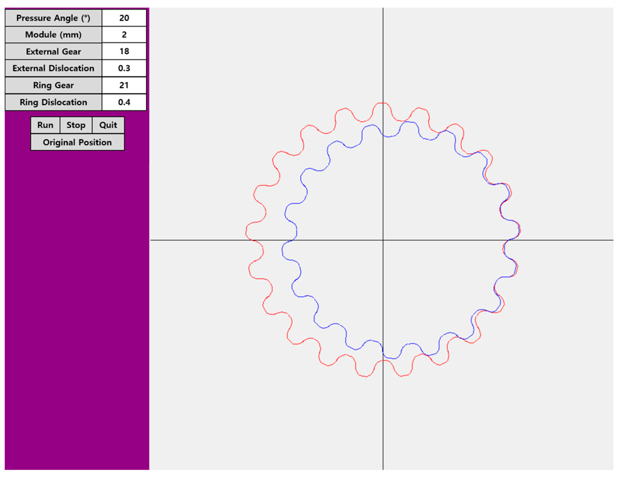
3.5. HTP Tooth Profile Design Software Using Python

Gear design with the HTP tooth profile—based on the IH tooth profile and the cycloidal curve—was implemented using Python. The design tool (software) was developed by applying the relevant tooth profile equations, allowing for the creation of gear tooth profiles based on various gear parameters. Using the developed HTP tooth profile design tool, gears with optimal shapes can be designed by following the flowchart shown in Figure 11.
Figure 12 shows a simulated cross-section illustrating the design results produced by the tool for a gear with an HTP tooth profile.
Figure 13 presents simulations of the meshing conditions for gears designed using the tool, for both a large number of teeth (z = 100) and a small number of teeth (z = 21). While the design of harmonic tooth profiles becomes challenging for small numbers of teeth, the proposed HTP tooth profile formulas allow for gear design regardless of the tooth count. Designers can use the simulation tool to assess gear meshing conditions based on selected design variables, enabling the creation of optimal tooth profiles that meet specific design requirements. The tool also allows for evaluation of meshing conditions, tooth interference, and related characteristics. As shown in Figure 14, gear tooth profiles can be successfully designed for both high and low tooth counts, with no interference observed in either case. The design parameters of the gear tooth profile in the corresponding figure are summarized in Table 2.

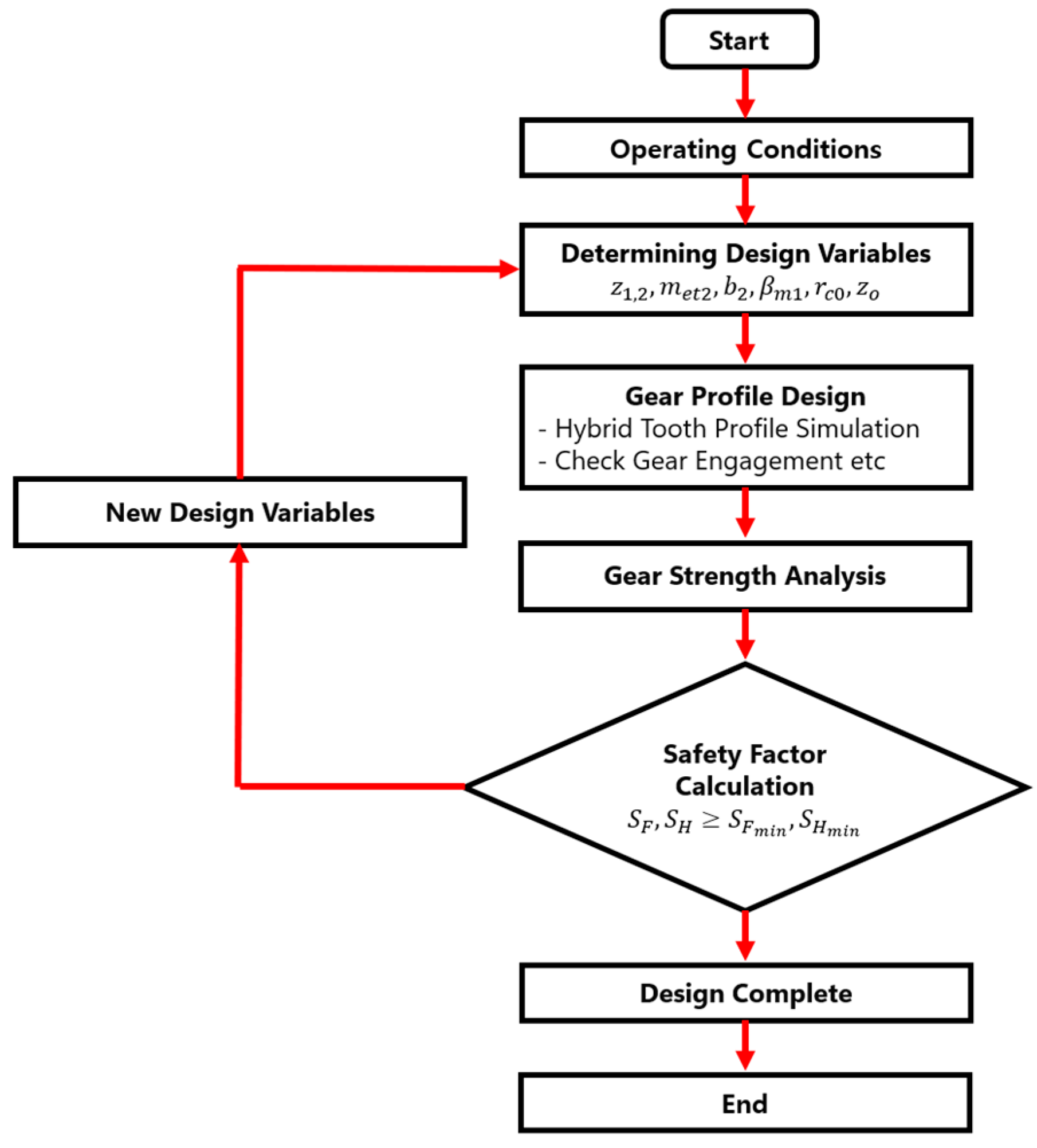
4. Design and Strength Analysis of an HTP Tooth Profile Reducer

4.1. Design of a Reducer with an HTP Tooth Profile Based on the IH Tooth Profile and Cycloidal Curves

The applicability of the newly developed HTP tooth profile, which integrates the IH tooth profile and cycloidal curves, was validated through the design of a high-reduction-ratio gear reducer. A one-stage reducer, designated as R21_z3, was developed for this purpose. The reducer features a three-tooth difference between the input and output shaft gears. The design specifications are summarized in Table 3.

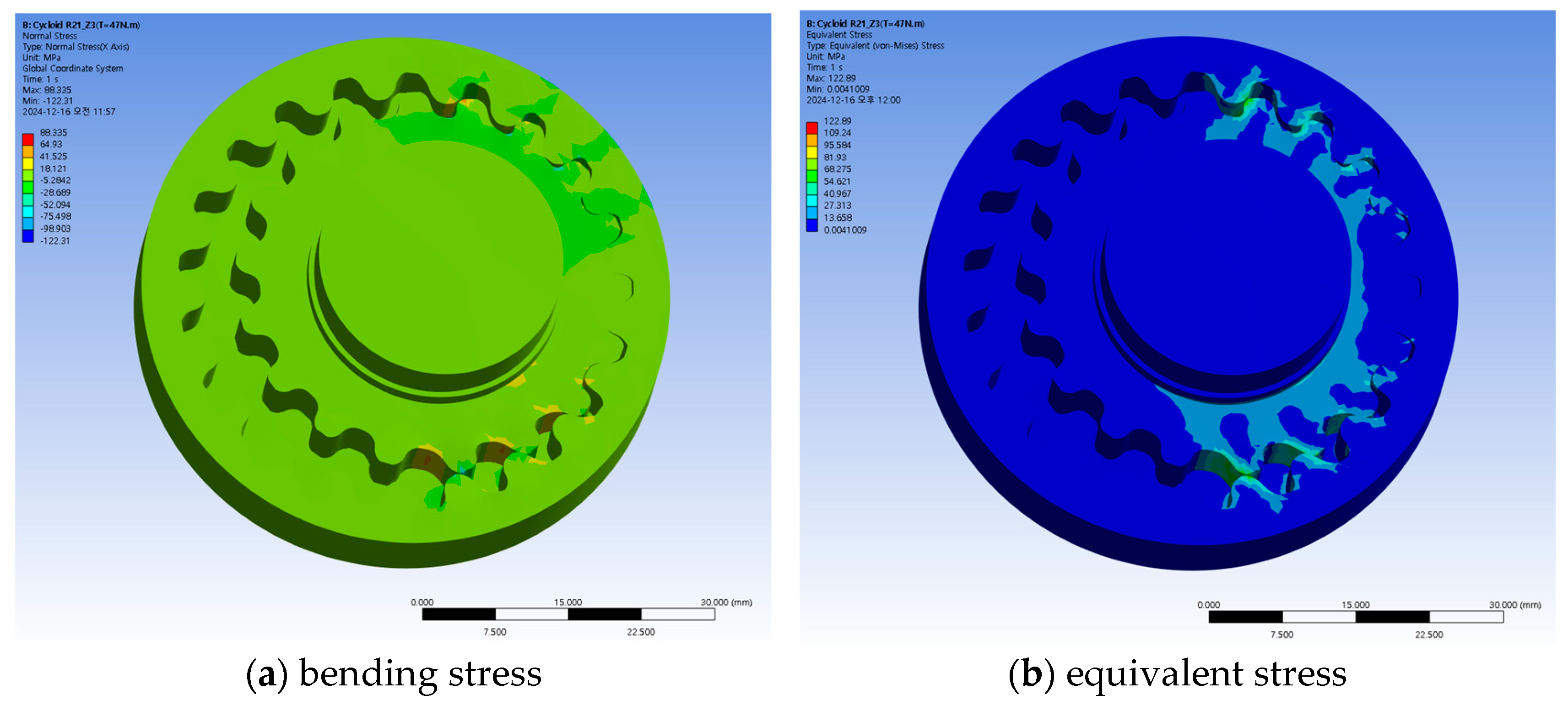
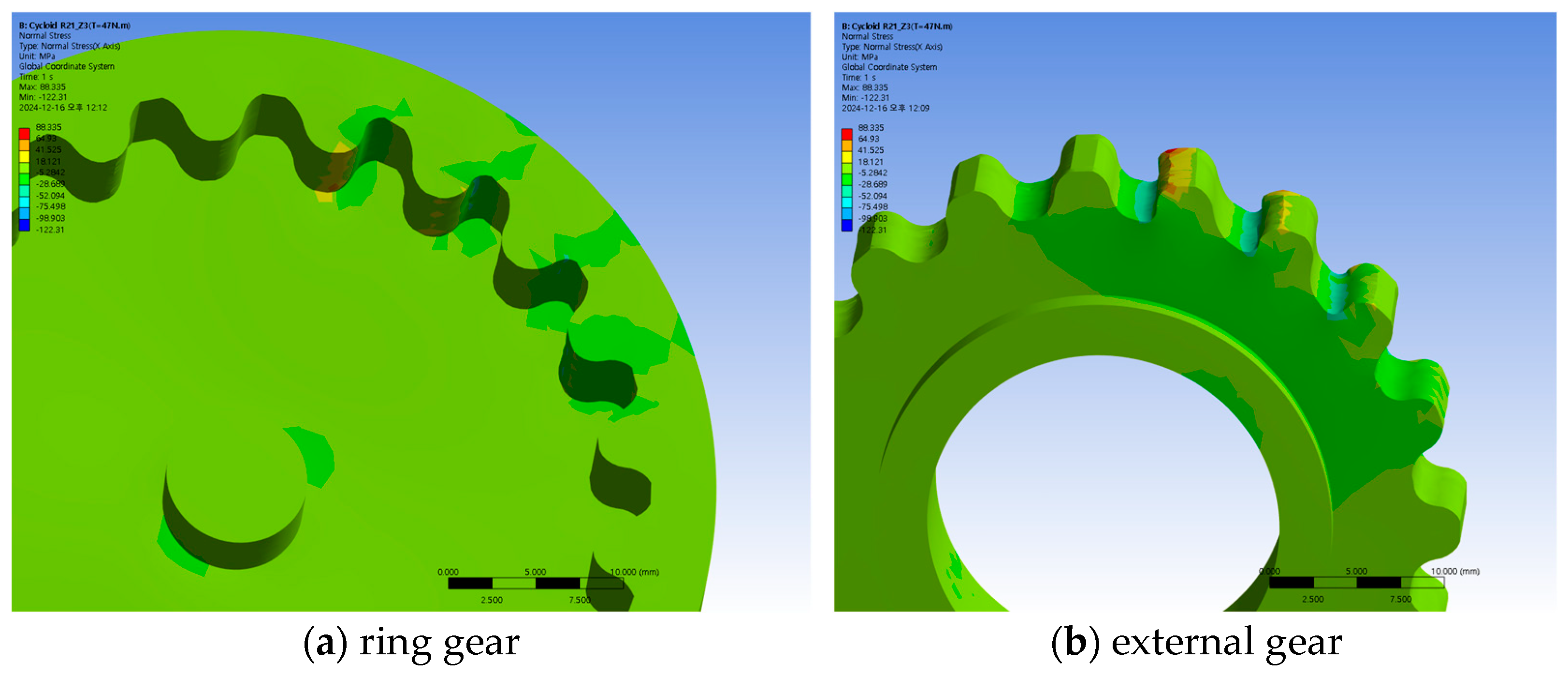
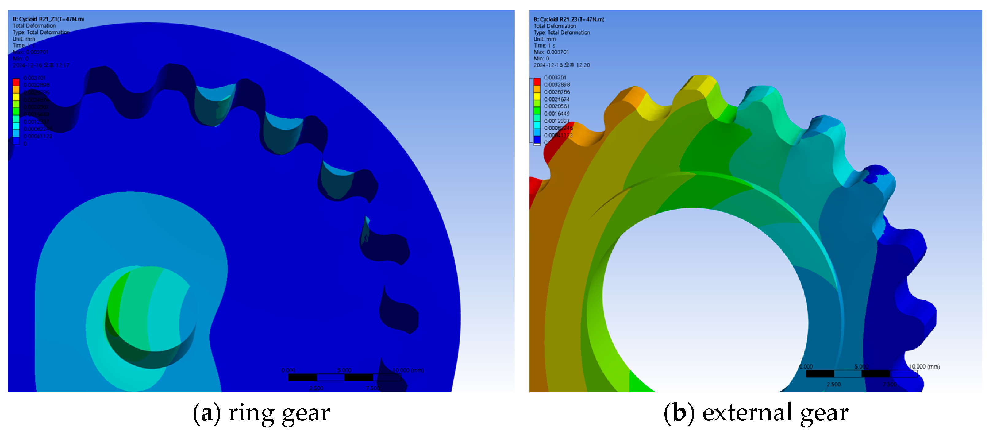
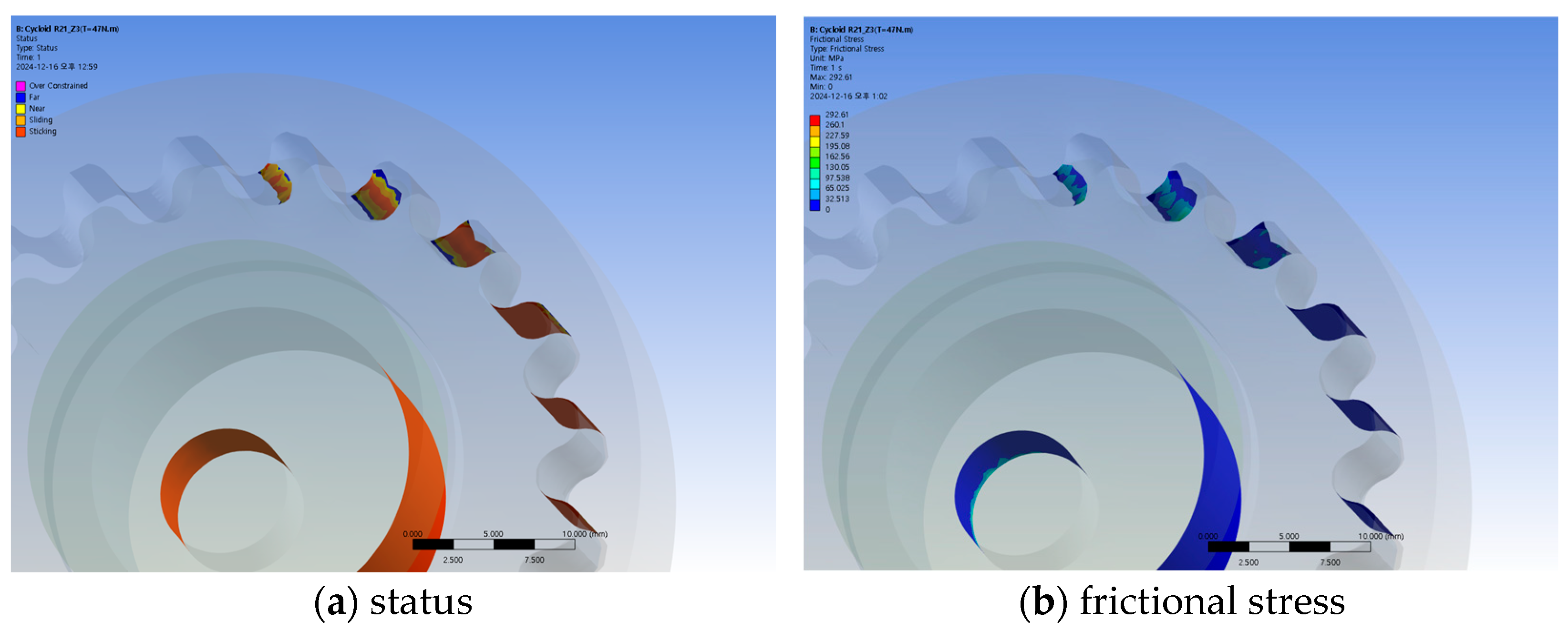
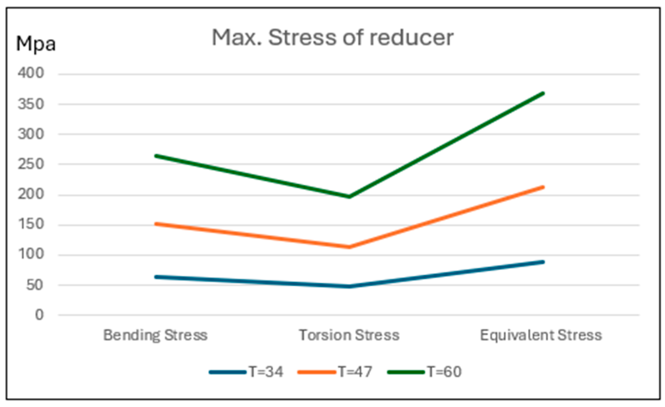
4.2. Strength Analysis of the Reducer

The strength analysis of the reducer was performed using the engineering analysis tool Ansys 2023 R2. In the analysis model, a fixed support condition was applied to the outer surface of the ring gear, and a torque of 47 Nm was applied to the eccentric shaft to evaluate the equivalent stress, bending stress, and total deformation in the area where tooth meshing occurs. The mesh was automatically generated based on the default settings of Ansys, but local refinement was manually applied to the gear tooth contact regions and the areas where stress concentration is expected. Element types used in parallel were SOLID186, a 20-node hexahedral element, and SOLID187, a 15-node tetrahedral element. To ensure the accuracy of the numerical analysis, the built-in convergence criteria of Ansys were used. For convenience, the material properties used in the analysis were those of general steel: density, 7.58 × 10⁻⁶ kg/mm3; Young’s modulus, 2 × 10⁵ MPa; and tensile ultimate strength, 460 MPa.
The distribution of bending stress and equivalent stress generated in the reducer is shown in Figure 14 for when a torque of 47 Nm is applied clockwise to the input shaft. At this time, the maximum value of the bending stress is 88.335 MPa, which occurs at the upper part, where tooth engagement takes place. The maximum value of the equivalent stress is 122.89 MPa and occurs in the same region as the maximum bending stress.
Figure 14. Stress distribution in Reducer R21_z3.
Applsci 15 05389 g014
As a result of the analysis of the stress distribution on the ring gear tooth surface, where the bending stress is highest, the stress distribution in the x and y directions is shown in Figure 15. The stress value in the X-direction of the tooth profile cross-section is 63.7% (56.232 MPa) of the maximum bending stress, while the stress in the Y-direction is 3.964 MPa, which is relatively small.
In addition, the total deformation of the R21_z3 reducer is 0.0037 mm, and the maximum deformation occurs in the direction opposite to the gear engagement region. The total deformation of the ring gear and external tooth gear is shown in Figure 16.
When a load torque of 47 Nm is applied to the R21_z3 reducer, the maximum contact stress acting on the tooth surface is 292.61 MPa, and this occurs on the ring gear, where tooth engagement takes place.
Figure 17 shows the contact condition and frictional stress distribution between the ring gear and external gear during meshing. As shown in the figure, as the clockwise load torque increases, the inter-gear tooth bite also increases until full engagement is achieved, after which the tooth bite gradually decreases.
Figure 18 shows a graph representing the main stresses in the R21_z3 reducer under varying load torque conditions. As shown in the figure, both bending stress and equivalent stress increase with the applied torque, and the equivalent stress shows a relatively larger increase with respect to the load.

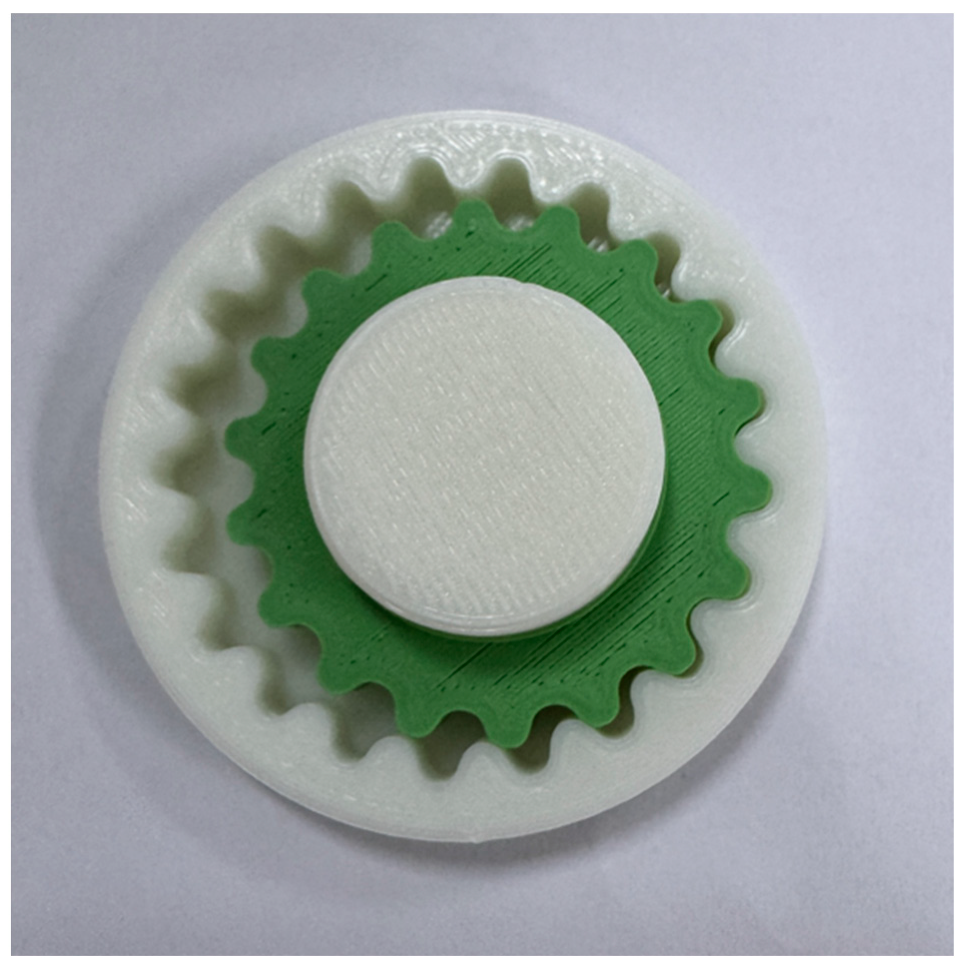
4.3. Prototype Fabrication of the Reducer

To check the actual engagement and driving conditions of the R21_z3 reducer, which was designed using the new HTP tooth shape based on the IH tooth profile and cycloidal curve, a prototype was produced by 3D printing using PLA material. Figure 19 shows the fabricated R21_z3 reducer. This prototype was manufactured in the form of a mock-up not for the purpose of evaluating mechanical performance under actual operating load conditions, but rather to qualitatively confirm the feasibility of realizing the HTP tooth profile shape, the continuity of the meshing structure, and the contact characteristics during operation. Through this, it was verified that the proposed HTP tooth profile equation can be implemented in an actual gear structure and that its geometric validity can be ensured. However, since PLA material has lower strength compared to the metal materials used in actual reducers, there are limitations in quantitative performance verification. In the future, a metal prototype will be produced to conduct quantitative experiments under real operating conditions, including transmission efficiency, stress, and durability.

5. Conclusions

A new HTP tooth profile design formula, based on the IH tooth profile and the cycloid curve, was proposed, and a corresponding reducer design tool was developed. Using this tool, reducers were designed for cases where the number of teeth in the ring gear was 21 and 100. Simulations were conducted to examine tooth meshing conditions, tooth interference, and related characteristics, confirming that no abnormalities occurred. In the case of a 21-tooth ring gear under a driving torque of 47 Nm applied to the input shaft, bending stress, equivalent stress, and other stress factors were evaluated through analysis. Additionally, a 3D prototype of the R21_z3 reducer with the new HTP tooth profile was fabricated to verify the meshing and operating conditions, thereby validating the proposed HTP tooth profile formula. The conclusions are as follows:
First, although it is theoretically difficult to design a reducer using the conventional IH tooth profile when the number of teeth is small, the proposed HTP tooth profile formula—incorporating both the IH tooth profile and the cycloid curve—enables reducer design regardless of the number of teeth.
Second, using the HTP tooth profile design approach, a Python-based reducer design tool was developed. Simulations conducted with this tool, under varying tooth counts, confirmed the absence of issues such as poor meshing conditions or tooth interference, thereby validating the reliability of the design tool.
Third, the R21_z3 reducer, designed using the proposed HTP tooth profile, underwent strength analysis—including bending stress and equivalent stress in the tooth meshing region—using Ansys 2023 R2. The analysis confirmed the validity of the design results.
Fourth, a 3D prototype of the R21_z3 reducer was fabricated, and physical verification confirmed that the meshing condition, tooth interference, and other design aspects matched the predictions from the design tool. Consequently, the overall validity of the proposed HTP tooth profile formula—based on the IH tooth profile and the cycloid curve—was confirmed through simulation, strength analysis, and physical prototyping.

Author Contributions

Conceptualization, S.O. and W.J.; methodology, S.O.; software, S.O.; validation, H.J., K.Y. and W.J.; formal analysis, H.J.; investigation, W.J.; resources, W.J.; data curation, W.J.; writing—original draft preparation, W.J.; writing—review and editing, S.O. and H.J.; visualization, W.J.; supervision, S.O.; project administration, H.J.; funding acquisition, M.L. All authors have read and agreed to the published version of the manuscript.

Funding

This work was supported by the Korea Planning & Evaluation Institute of Industrial Technology (KEIT); and the Ministry of Trade, Industry & Energy (MOTIE) of the Republic of Korea (No. 20024010).

Institutional Review Board Statement

Not applicable.

Informed Consent Statement

Not applicable.

Data Availability Statement

The original contributions presented in this study are included in the article. Further inquiries can be directed to the corresponding authors.

Conflicts of Interest

The authors declare no conflicts of interest.

References

  1. Nam, W.-K.; Oh, S.-H. A design of speed reducer with trapezoidal tooth profile for robot manipulator. J. Mech. Sci. Technol. 2011, 25, 171–176. [Google Scholar] [CrossRef]
  2. Ren, Z.Y.; Mao, S.M.; Guo, W.C.; Guo, Z. Tooth modification and dynamic performance of the cycloidal drive. Mech. Syst. Signal Process. 2017, 85, 857–866. [Google Scholar] [CrossRef]
  3. Jang, D.J.; Kim, Y.C.; Hong, E.P.; Kim, G.S. Geometry design and dynamic analysis of a modified cycloid reducer with epitrochoid tooth profile. Mech. Mach. Theory 2021, 164, 104399. [Google Scholar] [CrossRef]
  4. Li, T.; An, X.; Deng, X.; Li, J.; Li, Y. A new tooth profile modification method of cycloidal gears in precision reducers for robots. Appl. Sci. 2020, 10, 1266. [Google Scholar] [CrossRef]
  5. Thai, N.H.; Thom, P.V.; Trung, N.T. Experimental design and manufacture a pair of the internal non-circular gears with an improved cycloid profile. In Regional Conference in Mechanical Manufacturing Engineering; Springer: Singapore, 2021. [Google Scholar]
  6. Hsieh, C.-F. Traditional versus improved designs for cycloidal speed reducers with a small tooth difference: The effect on dynamics. Mech. Mach. Theory 2015, 86, 15–35. [Google Scholar] [CrossRef]
  7. Jia, H.; Li, J.; Xiang, G.; Wang, J.; Xiao, K.; Han, Y. Modeling and analysis of pure kinematic error in harmonic drive. Mech. Mach. Theory 2021, 155, 104122. [Google Scholar] [CrossRef]
  8. Kim, B.-S.; Jeong, S.-T.; Ahn, H.-J. The prediction of the angular transmission error of a harmonic drive by measuring noncontact tooth profile and considering three-dimensional tooth engagement. Int. J. Precis. Eng. Manuf. 2023, 24, 371–378. [Google Scholar] [CrossRef]
  9. Yang, C.; Ma, H.; Zhang, T.; Liu, Z.; Zhao, Y.; Hu, Q. Research on meshing characteristics of strain wave gearing with three different types of tooth profiles. Int. J. Precis. Eng. Manuf. 2021, 22, 1761–1775. [Google Scholar] [CrossRef]
  10. Tang, T.; Jia, H.; Li, J.; Wang, J.; Zeng, X. Modeling of transmission compliance and hysteresis considering degradation in a harmonic drive. Appl. Sci. 2021, 11, 665. [Google Scholar] [CrossRef]
  11. Wang, J.; Wan, Z.; Dong, Z.; Li, Z. Research on performance test system of space harmonic reducer in high vacuum and low temperature environment. Machines 2020, 9, 1. [Google Scholar] [CrossRef]
  12. Zhao, C.; Wang, X.; Liu, Z.; Liu, J.; Zhang, J. Research on static and dynamic mechanical characteristics of flexible bearing in harmonic reducer. Int. J. Adv. Robot. Syst. 2020, 17, 1729881420919953. [Google Scholar]
  13. Ishikawa, S. The gear geometry of tooth engagement in harmonic drive. In Proceedings of the JSME Semi-International Symposium, Tokyo, Japan, 4–8 September 1967. [Google Scholar]
  14. Ishikawa, S. Tooth Profile of Spline of Strain Wave Gearing. U.S. Patent No. 4,823,638, 25 April 1989. [Google Scholar]
  15. Kiyosawa, Y.; Sasahara, M.; Ishikawa, S. Performance of a strain wave gearing using a new tooth profile. In Proceedings of the 1989 International Power Transmission and Gearing Conference, Chicago, IL, USA, 25–28 April 1989; American Society of Mechanical Engineers: New York, NY, USA, 1989; Volume 2, pp. 607–612. [Google Scholar]
  16. Kondo, K.; Takada, J. Study on tooth profiles of the harmonic drive. J. Mech. Des. 1990, 112, 131–137. [Google Scholar] [CrossRef]
  17. Maiti, R. A novel harmonic drive with pure involute tooth gear pair. J. Mech. Des. 2004, 126, 178–182. [Google Scholar] [CrossRef]
  18. Cao, X.; Song, S.; Xie, H.; Wang, M. Design and analysis of double-arc tooth profile harmonic drive. In Recent Developments in Mechatronics and Intelligent Robotics: Proceedings of the International Conference on Mechatronics and Intelligent Robotics (ICMIR2017)–Volume 2; Springer International Publishing: Berlin/Heidelberg, Germany, 2018; pp. 19–29. [Google Scholar]
  19. Yu, Z.; Ting, K.-L. Explicit dynamics analysis for harmonic drives. In Proceedings of the International Design Engineering Technical Conferences and Computers and Information in Engineering Conference, New York, NY, USA, 25–28 August 2014; American Society of Mechanical Engineers: New York, NY, USA, 2014; Volume 46285. [Google Scholar]
  20. Li, Y.; Zhang, N.; Zhang, Y.; Dai, B. New Design Method for Flexspline Tooth Profile of Harmonic Drive Considering Deformation. In Proceedings of the 2019 IEEE 6th International Conference on Industrial Engineering and Applications (ICIEA), Tokyo, Japan, 12–15 April 2019; IEEE: New York, NY, USA, 2019; pp. 111–115. [Google Scholar]
  21. Xie, R.; Yang, Y.; Zhou, G.; Gao, B.; Jiao, Y.; Yu, R. A novel harmonic drive with the full conjugate tooth profile. Proc. Inst. Mech. Eng. Part C J. Mech. Eng. Sci. 2024, 238, 9748–9760. [Google Scholar] [CrossRef]
  22. Huang, J.; Xu, J.; Qian, N. Investigation on high contact ratio harmonic two-dimensional tooth profile design based on mid-point meshing method. J. Mech. Sci. Technol. 2023, 37, 835–850. [Google Scholar] [CrossRef]
  23. Juvinall, R.C.; Marshek, K.M. Fundamentals of Machine Component Design, 2nd ed.; John Wiley & Sons: New York, NY, USA, 1991; pp. 550–596. [Google Scholar]
  24. Jeon, H.-S. Study on the Flexspline for Harmonic Drive of Robots. Ph.D. Thesis, Chung-Ang University, Seoul, Republic of Korea, 1998. [Google Scholar]
  25. Ishikawa, S. Tertiary Negative-Deviation Flexing Contact Type Gear Drive of Non-Profile-Shifted Tooth Profile. U.S. Patent No. 5,458,756, 23 January 1996. [Google Scholar]
  26. Murayama, Y. Method for Designing Tooth Profile of Wave Gear Device. Korean Patent 10-2023-0147738, 23 October 2023. [Google Scholar]
Figure 1. IH tooth curve of harmonic systems company (S series)—redrawn.
Applsci 15 05389 g001
Figure 2. Diagram of motion trajectory and similar curve generation in IH tooth profile design.
Applsci 15 05389 g002
Figure 3. X-Y trajectory for each tooth curve.
Applsci 15 05389 g003
Figure 9. Shape of tooth engagement (λ = 1.0, and Br = 0.9).
Applsci 15 05389 g009
Figure 10. Tooth engagement shape for HTP.
Applsci 15 05389 g010
Figure 11. Gear design flowchart for HTP tooth profile.
Applsci 15 05389 g011
Figure 12. Simulated cross-section of HTP design results.
Applsci 15 05389 g012
Figure 13. Simulation of HTP tooth profiles for different numbers of teeth.
Applsci 15 05389 g013
Figure 15. Bending stress distribution on the tooth surface of the Reducer R21_z3.
Applsci 15 05389 g015
Figure 16. Total deformation distribution of Reducer R21_z3.
Applsci 15 05389 g016
Figure 17. Contact status of Reducer R21_z3.
Applsci 15 05389 g017
Figure 18. Maximum stress value corresponding to the change in load torque of Reducer R21_z3.
Applsci 15 05389 g018
Figure 19. Three-dimensional prototype of Reducer R21_z3.
Applsci 15 05389 g019
Table 1. Characteristics of tooth profiles in a speed reducer.
ParameterInvolute
Tooth Profile
Cycloid Tooth ProfileIH Tooth Profile
Tooth profile curveInvolute curveCircular curveStraight line and
circular curve
Contact ratio153030
Efficiency (%)9070–8080
Transmission error
(arc min)
12~31
Tooth root stress Reduction compared to involute tooth profile
Torque Improvement compared to involute tooth profile
Meshing stateInstantaneous
contact
Initial contact but separation in the
intermediate stage
Not in contact for just a moment butremains in contact consistently
Table 2. Tooth profile design parameters.
Parameter(a)(b)
External GearRing GearExternal GearRing Gear
Module1.41.422
Pressure angle (°)20202020
Number of teeth971001821
Profile shift coefficient0.650.60.30.4
Pitch circle diameter (mm)135.81403642
Center distance (mm)4.848-3.169-
Operating pressure angle (°)22.8-27.194-
Table 3. Reducer design specifications.
ParameterDesign Value
Module (mm)2.0
Number of teethRing gear21
External gear18
Tooth profilesHybrid tooth profile
Reducer ratio1/6
Eccentricity (mm)3.0
Pressure angle (°)20
Disclaimer/Publisher’s Note: The statements, opinions and data contained in all publications are solely those of the individual author(s) and contributor(s) and not of MDPI and/or the editor(s). MDPI and/or the editor(s) disclaim responsibility for any injury to people or property resulting from any ideas, methods, instructions or products referred to in the content.

