1. Introduction
The industry of automated vehicle systems has been operating for decades, providing novel solutions and mechanisms to cope with current problems related to traffic in modern cities. Advancements in advanced driver assistance systems (ADASs) [
1,
2] have provided human drivers with supportive tools to enhance the driving experience and improve road safety while maintaining a fine balance between responsibilities. For some time now, the industry has developed automated solutions that aim to provide a full level 5 technological platform capable of driving better and safer than any human driver [
3,
4]. However, there are still many challenges to be faced in this field [
5], and the more advancements that occur, the more potential flaws, opportunities, and paths are discovered to improve the current technology used. Generally speaking, automated driving is approached primarily by current state-of-the-art solutions from a selfish perspective in which the flow of information is local to the vehicle being controlled. The encapsulation of this information can lead to complex traffic situations with partial information. If poorly assessed, these situations can result in potentially unsafe decisions that can threaten other road users or the passenger’s life. A practical example of the previous fact is that real-world inference works over assumptions and hypotheses [
6], not providing fail-safe mechanisms with enough accuracy to cope with occlusions and blind spots of highly inaccurate measurements. Every sensor solution for real-world inference suffers from flaws related to the context and usage of readings from LiDAR and radar technologies to camera detection or GNSS localization. From past errors and mistakes, as well as unpredictable accidents, the industry is forced to evolve and learn by providing better solutions to cope with current limitations [
7]. Therefore, recognizing the challenges of insufficient information in traffic management, Connected Cooperative Automated Mobility (CCAM) [
8] provides a solution for improved distributed control and reduced risk of critical errors.
CCAM is expected to render a huge change in current technological solutions that only focus on selfish information. The capabilities to implement a distributed system aimed at collaborating and/or arbitrating between connected vehicles are the first step to solving the limitations previously explained. As a consequence, new and promising solutions for vehicular networks and V2X communications are providing a ground basis from which to generate the future communication layer for this to happen [
9,
10]. However, while these advancements take place, providing robust methodologies for communication between vehicles in future scenarios, some interesting research can be performed in parallel, hypothesizing about the possibilities of arbitration in current city environments. This is because not only is sharing perceptual information important, but so are the collaborative processes that can take place in complex traffic emplacement to enhance the traffic flow, which can potentially prevent unnecessary bottlenecks or improve routing for emergency situations. Because vehicular networks are still under development, defining a practical operational environment requires establishing certain constraints. Current efforts at the software level focus on using deep learning models to meet communication allocation needs [
11,
12], while hardware limitations are still a problem that requires constant testing [
13]. However, while advancements progress, further development of traffic agent arbitration and collaboration will establish a strong foundation for future benefits.
Conventional connected and automated vehicle (CCAV) coordination necessitates human intervention, employing a driver-in-the-loop hybrid cooperation model [
14]. Haptic feedback mechanisms, including visual or auditory signals, directly cue the driver to facilitate coordination with other traffic participants. However, excessive haptic cues can disrupt the driver, leading to overcorrection and degraded driving performance [
15]. Effective implementation requires human-machine interfaces capable of accurately predicting driver state. On the other hand, the introduction of traffic lights has significantly improved junction traffic performance by automatically controlling intersection entries. However, because they cannot dynamically adjust to the actual vehicle traffic, traffic lights appear to be less effective when there is a high demand over the network. The reason why this happens is primarily because the technology does not have the capabilities of adapting dynamically to the current traffic demand and acting in accordance with the context. To cope with this limitation, several approaches have been made, such as Virtual or optimized Traffic Signals [
16,
17], multiagent coordination [
18], and intelligent reservation control [
19]. While the first option provides a fast solution to the problem, there is still the issue of agent coordination and distributed collaboration. In that sense, intersection management based on resource allocation has the potential of benefiting from the opportunities offered by Connected Cooperative Autonomous Mobility, possibly coping with current challenges in critical traffic emplacements [
20] such as four-way intersections or roundabouts [
21]. The allocation of resources for arbitration within traffic management is not a recent innovation and has been subject to considerable discourse regarding its efficacy relative to classical policies [
22]. Previously related work, for instance, explored the same notion in common intersections, with the difference that the execution of the arbitration itself was assumed from a simulation instance, which has full control over its actors and lacks a reliable and realistic approach where the control operates instantaneously [
23]. Hence, the proposed models operate over a simplified traffic network whose structure was extracted from real-world information but with a simulated demand of traffic managed by a constant ubiquitous omnipotent hypervisor that knows everything at any moment, globally. Therefore, despite ongoing optimizations implemented with these tools, as seen in [
24,
25], there is insufficient effort dedicated to developing a framework for validating these advancements under more realistic scenarios.
This work presents an approach to complex traffic emplacement arbitration based on behavior collaboration between traffic agents, together with a framework focused on cooperation implemented with ROS [
26] and Carla [
27] based on multi-agent simulation [
28]. The proposed framework implements a distributed control architecture onboard each automated vehicle, enabling the centralized arbitration of resource reservation requests by evaluating individual vehicle intent and relative proximity. The notion of arbitration here is defined as the number of resources from the traffic emplacement that can be allocated in real time, providing a tool to select which vehicle is going to use that resource and which one should wait for it. The proposal is based on the presented idea of automated intersection management [
29]. This solution assumes all vehicles are connected and automated, allowing them to provide collaboration capabilities but also automated behaviors for navigation and planning [
30,
31,
32]. The main goal for these tools is to allocate the maximum slots of resources at a time state potentially improving the flow of traffic and allowing to select resources based on different parameters such as the priority, the number of vehicles waiting or a time limit for a specific resource. In this proposal, the basic foundation for the testing and validation of intersection management algorithms is presented. This solution provides a stack for behavior collaboration between distributed components that operate as standalone containers within the same network but with an independent software control architecture. This software ecosystem is responsible for automated tasks like localization, navigation, and control, but also decision-making and mission management. Finally, while previous works focus on intersections, this work provides a generalized framework that can operate in roundabouts and potentially any traffic emplacement with junctions.
This paper follows a logical flow mirroring the design and implementation of the proposed methodology.
Section 2 details the proposed arbitration ecosystem and its components.
Section 3 explains traffic infrastructure representation and map recognition.
Section 4 describes the tracking process for arbitration, emphasizing vehicle–infrastructure interaction. This leads to
Section 5, which presents the complete arbitration process and information exchange.
Section 6 proposes an arrival-time-based optimization to enhance real-time arbitration.
Section 7 presents the experimental setup, results, and validation methodology. Finally,
Section 8 and
Section 9 offer discussion, key observations, and conclusions with future research directions, including commentary on the paper’s findings.
2. Ecosystem Containers
Before detailing the arbitration ecosystem, it is crucial to outline its foundational components. This system is structured into two key containers: the vehicle and the infrastructure containers. These are implemented using middleware platforms like ROS, leveraging its collection of interacting services for modularity and flexibility.
2.1. Vehicle Container
The vehicle operates as an automated and connected platform with localization, control, navigation and decision-making capabilities. These skills are provided by a complete architecture of control in which different layers focus on assorted responsibilities [
33]. These modules are implemented to supply most of the four capabilities needed for arbitration to happen during the collaboration:
High-Definition Map module: That is the
HD Map module, able to provide a stack for interaction with HD maps for automated driving [
34,
35]. The module parses an ASAM Opendrive file [
36] containing the complete road network for navigation and map localization.
Planning module: This is the
Waypoint Manager, based on a tree structure search engine [
37,
38,
39], and it is able to provide a high-level road plan to follow and localize the vehicle with respect to it. The module implements a search algorithm to localize the vehicle with respect to the plan, allowing the trajectory generation and path-following modules to work with sufficiently accurate information.
Cooperative module: This is the Cooperation Manager, which is able to process incoming and outgoing collaborative information. The module represents the basic layer of communication between connected containers, whether an intelligent infrastructure component or another connected vehicle.
Mission module: This is the
Mission Manager [
31], which is able to provide global and local behaviors based on contextual information, including requesting a connection to the infrastructure container. The
Mission Manager is responsible for managing the contextual awareness and the resulting behaviors, depending on the navigation profile. This is performed through the
Advanced Behavioral Point (ABP) [
31] concept, a strategic point distributed and integrated into the software architecture [
33] of an automated vehicle control system using a mission system and a route plan.
On the one hand, the contextual information mentioned above required by the
Mission Manager comes from the Traffic Scene notion described in the work [
33], where all information related to the current traffic context is depicted. The representation of the context is based on the following components:
Road Events: Events generated by the vehicle navigation system to produce localization, planning, and map information for high-level movement commands. Used primarily for motion and path planning features.
Perception Events: Events generated from the perception system of the automated vehicle with perceptual information for cruise control, collision evasion and overtaking maneuvers.
Cooperation Events. Shared events with collaborative information, such as perceptual data coming from connected traffic agents’ perceptual systems.
Awareness Events. Internal managed events with information about the system operating on the platform and its status. Primary source of anomaly detection.
These items completely describe all dynamic and static elements for the vehicle to operate automatically on the road. On the other hand, the decision-making is implemented using behavior trees [
40] deployed dynamically through the road plan with
Advanced Behavioral Point (ABP) [
31]. These ABPs are a key component for the arbitration to work because they represent the information that is being interchanged between containers. These ABPs can be added, updated, and removed dynamically from the mission on demand, changing effectively the mission in real time depending on the context. There are three main components that define the ABP:
ID: An identifier that correlates the ABP with a behavior tree to load when chosen. This identifier is taken at runtime and used to find and load, from among those available in the database, the behavior tree that best fits the current situation. This database is designed to grow in complExity for more robust behaviors.
Planning Waypoint: A waypoint that locates the ABP with respect to the road plan the vehicle is currently following. The waypoint stores Cartesian and Frenet coordinates [
41] that allow the navigation system to select the closest ABP ahead to deploy.
Behavior: A custom behavior field to provide a collaborative behavior if it is not found in the database. This field can be used as a suggestion from the infrastructure. In that case, behavior collision is solved locally in the Mission Manager deployed in the vehicle container.
In
Figure 1, a complete view of the elements described for the container can be seen. As can be seen in
Figure 1, the notion of
Traffic Scene is composed of different information elements such as the HD Map (red arrows and black lane IDs), landmarks (traffic light signs), ABPs (green squares and orange circles), road planning (blue and green roads), perception events (colored bounding boxes), and the localized vehicle model.
Following the vehicle container, the next key component for arbitration is the traffic emplacement and its capabilities. The idea proposed here is to have multiple vehicle containers operating on the roads with the capability to connect to a traffic emplacement for negotiation and arbitration purposes. For that specific task, a new container that encapsulates the traffic infrastructure skills is needed: the infrastructure container.
2.2. Infrastructure Container
The infrastructure container is responsible for tracking each vehicle to which a resource was assigned and determining when a vehicle uses it or waits for it by modifying the mission of the vehicle that requests the connection. These modifications come in the form of ABP suggestions for the effective arbitration to take place using the behavior field mentioned in previous sections. The following modules are required for this purpose:
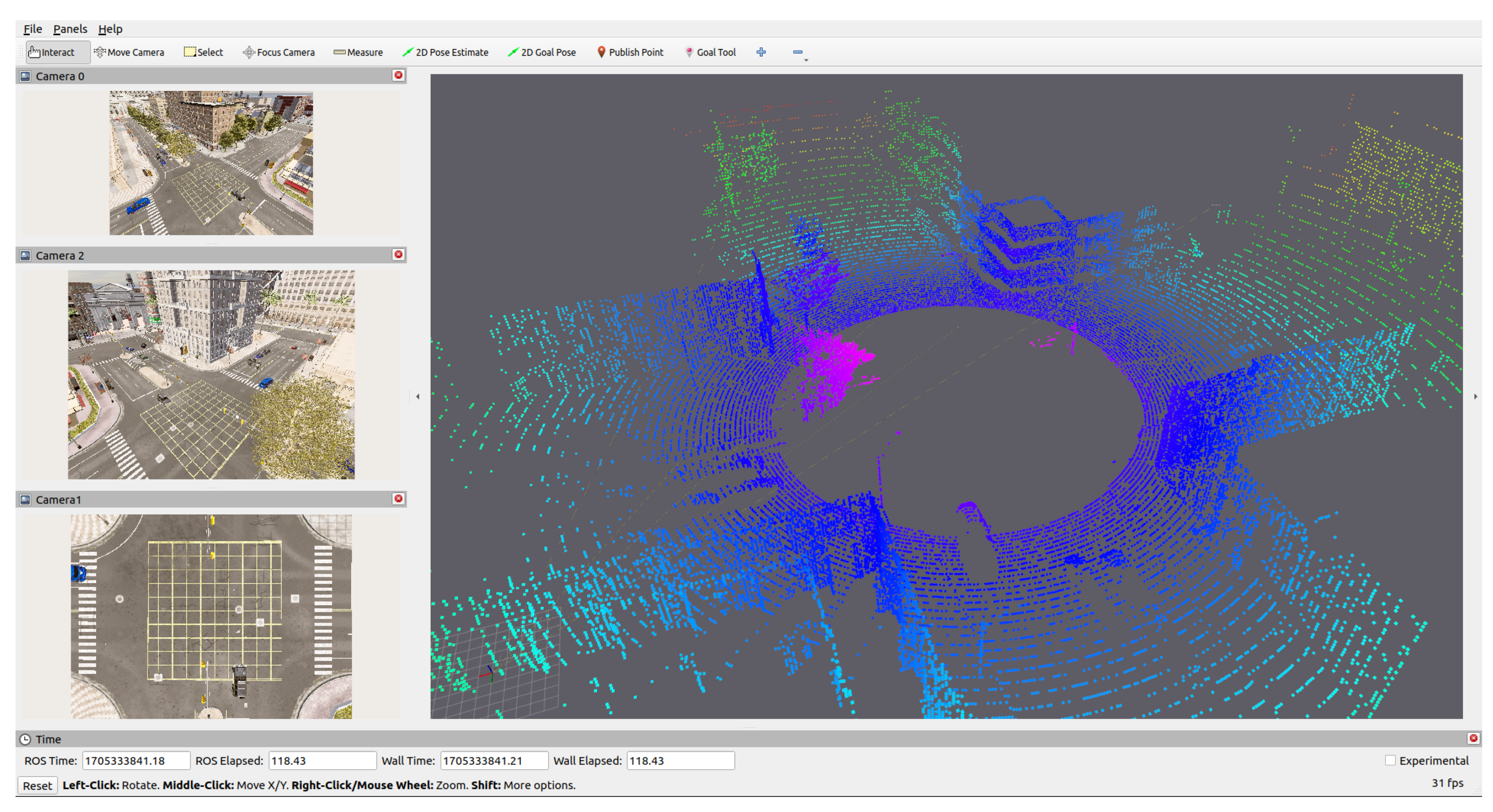
Figure 2 shows how the traffic emplacement (intersection) is deployed and sensorized with multiple cameras and a LiDAR sensor prepared for data fusion in real time. Several fusion algorithms exist, each with trade-offs, including deep learning models like DeepFusion [
43], TransFusion [
44], and BEVFusion [
45]. These algorithms employ different fusion strategies such as raw sensor data fusion, independent detection fusion, or final prediction fusion. The main goal of this awareness set up is to provide a perception model with enough accurate contextual information to detect, track and classify incoming vehicles and then integrate those detections into the internal tracking system of the arbitration component, fusing information coming from the cooperative system and the perception inference presented as final perception events, presented in [
33], associated with a score representing the uncertainty of the measurement. This effectively allows the management system to implement a more robust tracking methodology based on multiple information sources distributed throughout the network of cooperative systems.
On the other hand, the localization module integrates Global Navigation Satellite System (GNSS) and Inertial Measurement Unit (IMU) data, fused via a Kalman filter [
46] to yield high-accuracy pose estimates enhanced by Real-Time Kinematic (RTK) corrections. This configuration enables the management system to establish accurate localization with respect to an East–North–Up (ENU) origin, facilitating the precise generation of world frame information for virtual environment construction. Finally, after describing the arbitration ecosystem components, in the next sections, the purpose, responsibilities and interaction for each relevant module are going to be described. These modules are the foundation of the collaborative processes that will take place during the arbitration.
3. Infrastructure Map Recognition
Automatically generate a valid environment for the arbitration requires carefully examining and constructing relevant areas of surveillance within a specific world location. These areas come from the traffic network parsed from the HD map stored in the ASAM Opendrive file. Each relevant surveillance area constructed represents a resource that can be shared among new connections with some conflict areas defined as hard restrictions for the arbitration engine to manage. The relation of these relevant areas is formalized as the logic of the emplacement is constructed, with Entry, Exit and control areas that will serve as main Entry points to detect threats and track new connected vehicles.
3.1. Control Area Definition
In
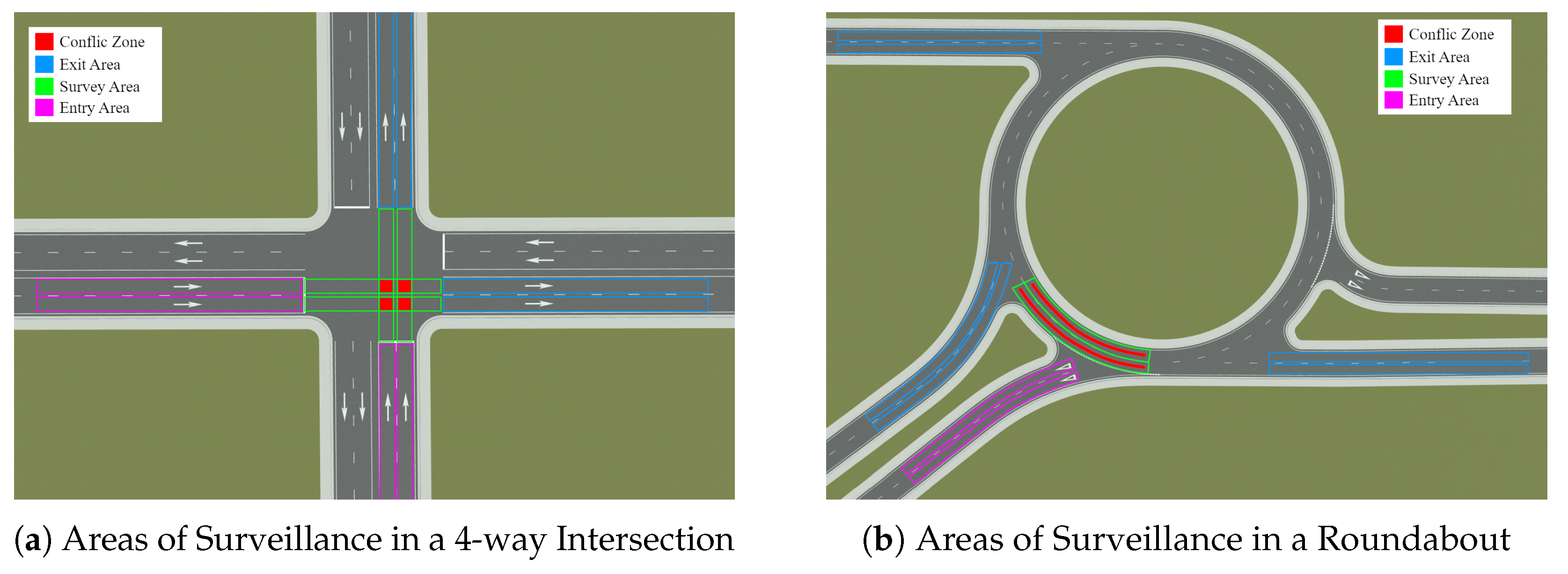
Figure 3 the idea behind this notation can be found. In
Figure 3a, a four-way intersection is depicted, while in
Figure 3b, a roundabout is shown. As can be seen, for each relevant traffic emplacement, Entry (Pink), Survey (Green), and Exit (Blue)
Control Areas are generated, marked as colorized polygons constructed from the lane geometry information. From each
Control Area, the conflict zones (Red squares) are defined, where the compatibility between incoming vehicles and the allocated resources are checked. Note that, for the sake of clarity, not all relevant areas are drawn in
Figure 3.
On the other hand, the allocation of resources is defined based on compatibility using Survey Clusters, where a cluster is a tuple of three items: Entry, Exit and Survey lanes. Each item is a control area defined by a set of unique roads, recognized by the ID provided in the HD Map. Each Exit and Entry area contains the Exit and Entry point, respectively, in local coordinates of the infrastructure map and global GNSS coordinates from a known ENU origin. At start-up, each cluster found in the traffic emplacement is constructed from a map intersection lane by assigning each control area mentioned and computing the Entry and Exit points found in the logical connections of roads.
The relevant roads chosen for this process are included within an arbitrary radius from the GNSS position reported by the localization module of the infrastructure set of sensors. All roads that are not inside this radius are not surveyed and are excluded from the internal map. Hereinafter, each control area is inflated with a polygon to check for the object intersection so that the system knows how many vehicles are located inside each cluster, providing a matching mechanism to track with respect to the map new incoming vehicles. It is worth mentioning that the generation of the cluster is dependent on the emplacement; therefore, the automatic recognition tool implemented is expected to render different results depending on the HD Map information. For intersections, the system searches automatically for intersection-type lanes within the radius provided. For the roundabouts, the system searches for entries adjacent to an intersection lane whose distance is minimal.
3.2. Cluster Compatibility Logic
After finding the relevant lanes, the control area is built based on an arbitrary longitudinal distance of coverage that can be adjusted as needed. Then, cluster compatibility is calculated by evaluating the intersection of the monitored lanes comprising each cluster. When a lane intersects with another lane, the corresponding cluster is marked as non-compatible; if there is no intersection, it is marked as compatible. The result is a list of clusters with compatible and incompatible clusters defined. This process is fully automatic for both types of environment, e.g., intersections and roundabouts, with slight differences between them that will be explained in more depth in the next sections.
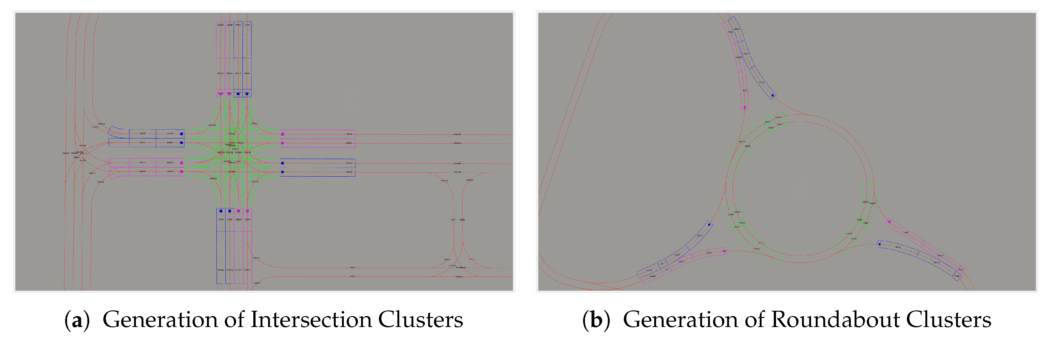
In
Figure 4, the result of the procedure applied to generate the set of
Survey Clusters explained in previous sections can be seen depicted with each
Survey Cluster composed of its
Entry area (pink polygons), its
survey area (green polygons), and its
Exit area (blue polygons). Note that each
Survey Cluster is identified with Entry, Exit, and Survey area; thus, several clusters can share the same Entry or the same Exit, which declares a possible incompatibility, but never both. At the same time, each relevant area within the generated
Survey Cluster can contain one or more roads, which are automatically assigned by reading the High-Definition Map and processing the logical contacts and geometrical information stored in the network topology. These lanes will be useful for tracking and positioning procedures. Furthermore, since multiple Entry/Exit areas can be shared among clusters, they are implemented with shared memory for the sake of efficiency. In addition, Entry and Exit points are placed as colorized squares in relevant Exit and Entry areas, which mark the local Cartesian coordinates as waypoints for the ABP suggestions when a new incoming vehicle mission is shared.
On the other hand, High-Definition Map information, such as roads and lanes (red arrow lines), and lane IDs (black numbers), which are crucial for the planning system, are shown. These lanes contain important geometric and semantic information, with Cartesian and Frenet waypoints parameterized with a 0.5 m distance between each point. This information is not only useful for the vehicle but also for the tracking process implemented on the infrastructure side. Moreover, although the conflict areas are not shown in this Figure, they are managed internally by the arbitration engine in real-time, since the compatibility of conflict zones depends on the resources currently using the emplacement arbitrated. Finally, note that the visualization provided comes from the framework in which the arbitration system was implemented and tested, i.e., Rviz, from ROS2.
Figure 4a shows the process applied to a four-way intersection; conversely, in
Figure 4b, the result of the same process applied in a roundabout can be seen with the same information extracted from the HD Map, and
Survey Clusters found in
Entry and
Exit lanes. As can be seen, the only difference between both paradigms can be found at the arbitration level since the
Survey lanes of the intersection are actual intersected lanes that generate conflict areas, while in the roundabout, these are survey lanes near the entrance where the detected vehicles are checked to ensure a free area for any vehicle entrance. These survey lanes are used in a different manner by the roundabout arbitration system since the conflicting area is found within the cluster itself; i.e., each cluster is compatible with itself, depending on the vehicles using its resources. Given the logical roundabout structure, this makes more sense than defining the compatibility between each other.
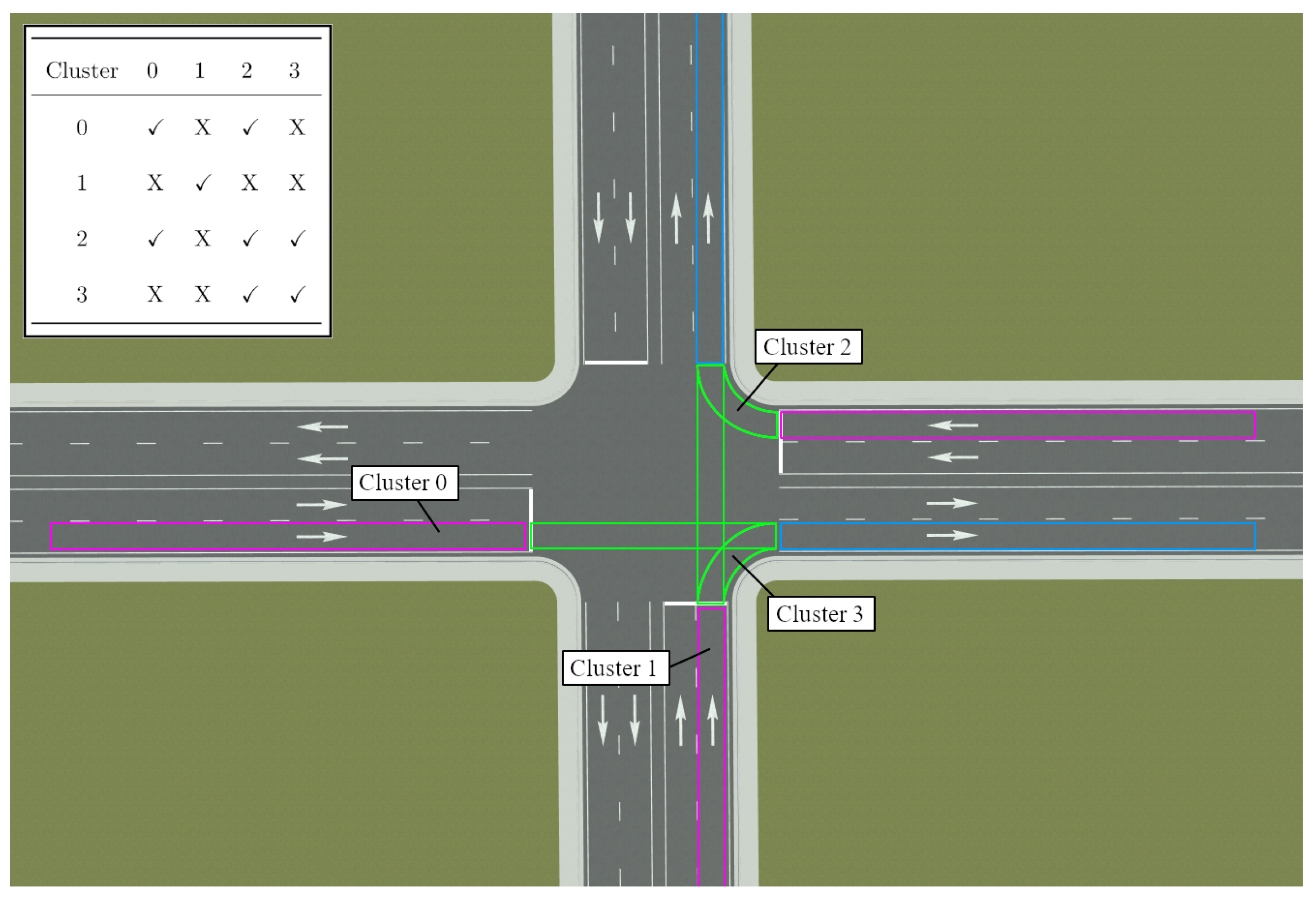
To clarify how this compatibility is constructed, in
Figure 5, the relationship between
Survey Clusters is depicted considering an intersection topology. The figure represents four intersection
Clusters with several conflict zones. In the top left corner, the cluster compatibility matrix considering Entry/Exit pairs is depicted. As can be seen, not only are cross-sections used to compute the compatibility, but so are shared Entry/Exit lanes.
Finally,
Table 1 details the main differences in traffic emplacement generation, considering cluster generation, compatibility, and topology-specific features.
Section 7.2 provides a more in-depth feature explanation.
3.3. Algorithmic Implementation
In Algorithm 1, the whole process to generate the set of
Survey Cluster can be found. This algorithm prunes, with the
parameter, non-relevant roads from a
gnns_enu position extracted from the GNNS solution deployed at the emplacement and converted to local infrastructure coordinates given an ENU origin. Then, the algorithm iteratively constructs each control area from the intersection type lane, aggregating each Entry, Exit and Survey area to a new
Survey Cluster given its logical contacts (successor and predecessor lanes). Therefore, when adding the next lane to each cluster, the control area is expanded with the logical contacts (successor/predecessor,) and then, a
parameter is added as a threshold to customize the length of the generated area. Upon generation of the operational monitoring environment, depicted in
Figure 4, the subsequent step entails the definition of the connection protocol and the implementation of a tracking mechanism for cluster resource allocation. For these specific features, the system generates several virtual landmarks like the Entry and Exit points, as well as the survey lane in which the Cooperative Connected Automated Vehicle is going to be tracked.
| Algorithm 1 Cluster generation from the map |
- 1:
- 2:
procedure Generate Cluster() - 3:
- 4:
for each do - 5:
- 6:
if then - 7:
- 8:
for each do - 9:
while do - 10:
- 11:
+= - 12:
end while - 13:
- 14:
end for - 15:
- 16:
end if - 17:
end for - 18:
end procedure
|
Finally, the proposed algorithm exhibits favorable computational efficiency, achieving an average processing latency of ≈75 ms with a
space complExity to generate the
Survey Cluster set from the provided map data. These results may depend on the hardware used and the configuration of the Map recognized, but they were consistent with the test cases proposed in
Section 7.
4. Infrastructure Tracking Node
Once the map is read, the system is able to process connection requests from incoming vehicles. For this interaction, the infrastructure container in
Section 2.2 implements a
Tracking Node, and the vehicle container implements the
Cooperation Manager. The
Tracking Node represents a dynamically instantiated software module within the infrastructure container, designed to provide real-time monitoring services while ensuring good operational integrity and performance for each managed vehicle. On the other hand, the
Cooperation Manager generates a tunnel from which to share information between containers.
Given an ABP in the current vehicle road plan whose behavior aims to request an infrastructure connection, the Mission Manager executes a vehicle container request, once the ABP required distance is reached, making a connection to the infrastructure. At that point, a connection is created between the infrastructure container and the vehicle container, which, with the Cooperation Manager, sends a data package to the Tracking Node of the infrastructure with some required information. This data package contains the following information:
Exposed Topics
- –
GNSS Topic: Data channel from which to listen to GNSS information.
- –
Mission Status Topic: Data channel from which to listen to Mission status info. Used for the interaction process.
- –
Vehicle Control Topic Data channel from which to listen to vehicle control information with the control variables of throttle, brake, speed, steering, etc.
Exposed Services
- –
Remove/Add/Update ABP: Vehicle services to change mission ABPs.
- –
Get Mission: Vehicle service to obtain the current mission of the vehicle.
- –
Get Plan: Vehicle service to obtain the current road plan tracked by the vehicle, used to retrieve the vehicle plan and select a proper Survey Cluster.
- –
Waypoints: Vehicle service to retrieve planning waypoint information in coordinates compatible with the vehicle operational coordinate frame.
- –
Map Origin: Service to retrieve map origin for coordinate transformation between containers coordinates.
Exposed Variables
- –
Coop ABP: ABP responsible for the cooperation interaction in vehicle local coordinates. This ABP is shared between the vehicle and infrastructure container.
- –
Vehicle Namespace: Operational namespace of the automated system that is requesting a connection. This is restricted to the ROS environment.
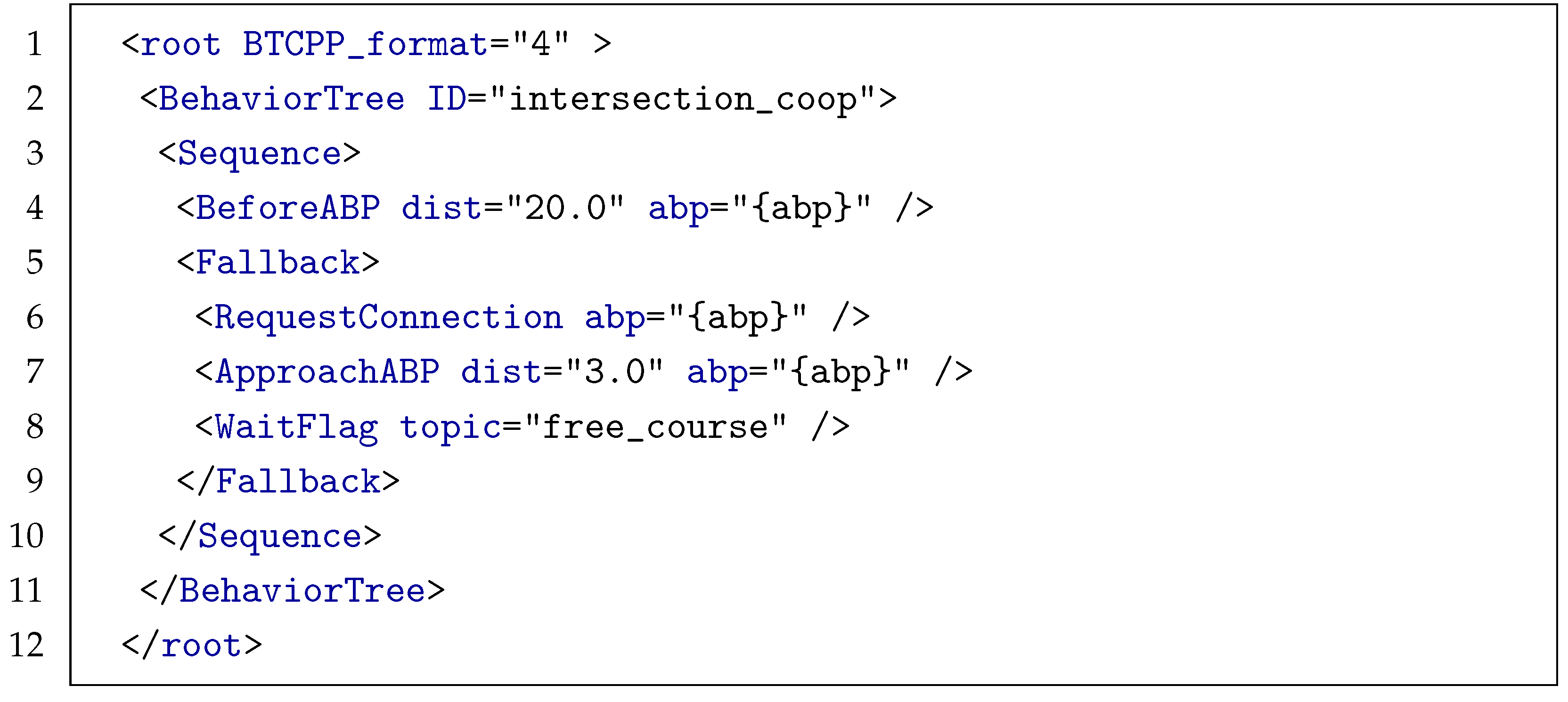
Once this information is received in the infrastructure container, the Tracking Node requests the localization, mission and planning information of the vehicle. When this information is received, the Tracking Node processes the planning, i.e., road plan, to find a suitable Cluster for the incoming vehicle. If this search fails, a redundant method is deployed to find the cluster with the current mission of the vehicle, traversing each ABP in the mission to find a suitable one that can relate to Entry and Exit points. If both searches fail to find a cluster, a cluster cannot be assigned, and the fallback action defined is executed. This fallback action represents a fail-safe execution that is meant to be defined in the behavior tree of the ABP when an unexpected behavior leads to a failure. Depending on the emplacement, the fallback can execute assorted behaviors, such as a prudent approach while reconnecting. In the provided Listing 1, an example of such behavior can be found.
| Listing 1. Example of Connection Behavior. |
![Applsci 15 05347 i001]() |
As can be seen, the behavior follows a behavior tree XML format of Sequences and Fallbacks that spawn from a root. The sequence executes each action consecutively; in this case, the BeforeABP marks the distance at which to start the next action. Then, the fallback section follows, which executes actions until one is successful. The first action, RequestConnection, tries to request a connection to the infrastructure management system. The management system receives this request through the services provided in the data package and starts searching for a Survey Cluster to assign to the vehicle. If the search is successful, the infrastructure container assigns the Cluster found to the vehicle that requested the connection, and the behavior finishes. The Tracking Node stores a reference to the Cluster that is used to track the vehicle and concurrently manages the resources of the traffic emplacement. If the Cluster cannot be found with current information, it is not assigned, the action fails, and instead, the behavior executes the fallback that defines a prudent approach to the ABP (ApproachABP action) and a wait-and-retry connection execution (WaitRetry action that listen to the topic stop to release the wait flag).
The search process to find a suitable
Cluster given the planning and mission information retrieved from the vehicle container can be seen in Algorithm 2. This algorithm requests the
from the vehicle planning layer and then filters with the
parameter only relevant lane types. Then, it computes the middle point of the current road processed and compares each of its lanes with each
Survey Area lane of each
Survey Cluster. The closest point matched belongs to the
Survey Cluster that will be assigned to the
Tracking Node. The same procedure can be used with Mission information; the only difference is that, instead of using planning roads, the algorithms use ABP poses, for which it converts vehicle coordinate ABP poses into infrastructure local coordinates. After this process, the vehicle is tracked by the
Tracking Node, starting to retrieve navigation information from the vehicle container. Afterward, the arbitration can take place by executing the
Tracking Node associated with the vehicle and the
Cluster selected.
| Algorithm 2 Find cluster with plan |
- 1:
- 2:
- 3:
procedure Find Cluster with Plan() - 4:
- 5:
- 6:
for each do - 7:
for each do - 8:
- 9:
end for - 10:
for each do - 11:
if then - 12:
- 13:
end if - 14:
end for - 15:
end for - 16:
- 17:
end procedure
|
This last algorithm reports an average processing latency of
ms with an
space complExity to find the
Survey Cluster set from the provided cooperative information, which, in the best case, is extracted directly from the Road Plan. These results may depend on the hardware used and the configuration of the
Survey Cluster set stored in memory, but they were consistent with the test cases proposed in
Section 7.
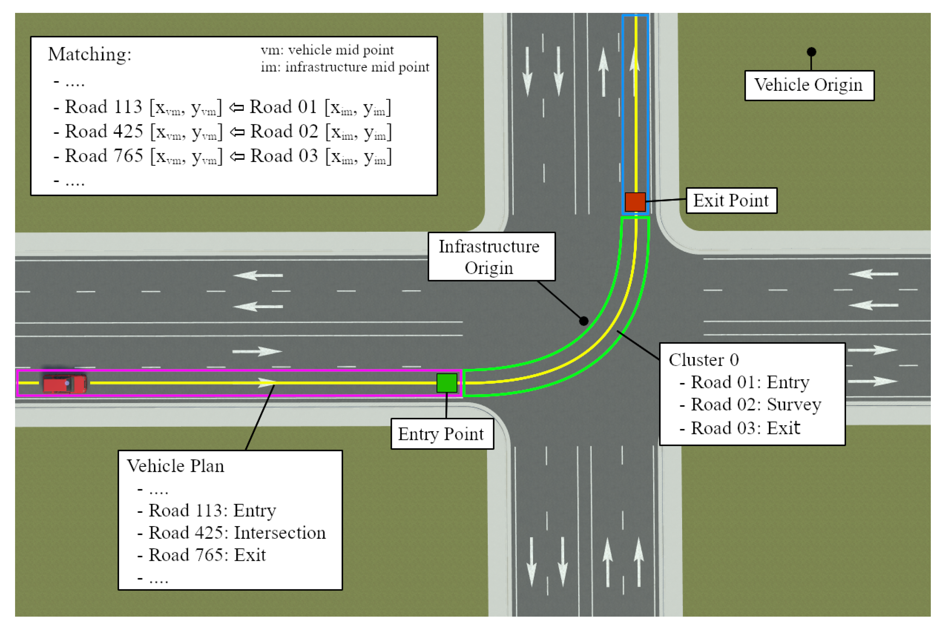
Finally, in
Figure 6, a visual representation of this process to find a
Cluster can be found. In this figure, a vehicle is approaching the intersection; yellow lanes represent the road plan the vehicle is following, which is shared with the infrastructure to find a suitable
Cluster. Due to differing vehicle and infrastructure map origins, a coordinate conversion occurs when comparing midpoints. Based on matched Entry, Exit, and survey lanes, the infrastructure assigns a
Cluster and places an ABP using transformed Entry and Exit coordinates, which are then communicated to the vehicle in its coordinate system.
5. Arbitration Process
The arbitration takes place within the infrastructure container by processing the set of Tracking Nodes currently being executed. Depending on the information retrieved by the Tracking Node and the current configuration of the Clusters in use, the system tries to find a compatibility set, i.e., a group of clusters that can be simultaneously used without conflict, which contains the maximum number of compatible clusters available. To accomplish this, the arbitration algorithm employs a constrained cost function based on a first-come, first-served model, prioritizing vehicles by arrival time while considering velocity, proximity, and resource compatibility. The management system maximizes emplacement capacity by optimizing resource allocation based on these parameters and current resource utilization. A decision is then made in real time, limited by software at approximately 20 Hz, which follows this process:
For each Tracking Node, find a compatibility set with other active nodes.
From the list of compatibility sets, select a set available. This selection can be based on priority or other information such as speed, type of vehicle, amount of waiting time, etc. Furthermore, useful prediction parameters such as the ones obtained from traffic forecasting models [
47,
48,
49] can be used to improve the selection and cost function performance. For the moment, the selection is made by taking into account only the speed and position, but this can be adjusted by updating the selected cost function with relevant parameters such as the vehicle type, Time-To-Collision, waiting/estimated time, number of stops, or even the number of waiting vehicles at Entry.
For each Tracking Node whose Cluster is compatible, the entrance is allowed and the Cluster is marked as used, which is a cluster currently assigned and actively traversed by a vehicle.
For each node that is not compatible with the compatibility set chosen, place an Entry ABP to define how those vehicles should approach the intersection. In both options, an Exit ABP is also added to the mission in order to mark when the vehicle finishes the tracking.
For each Tracking Node that is compatible but also mission-ready, i.e., a vehicle that was previously arbitrated and is in a state to act on the decision, check with the behavior execution status if it is approaching or waiting. If it is approaching, remove the Entry point to allow entrance. If it is waiting, release the waiting flag for the behavior to finish, and release the vehicle captured, allowing the vehicle to continue with its plan.
Once other Tracking Nodes Exit the intersection, evaluate the compatibility set again, and restart the process.
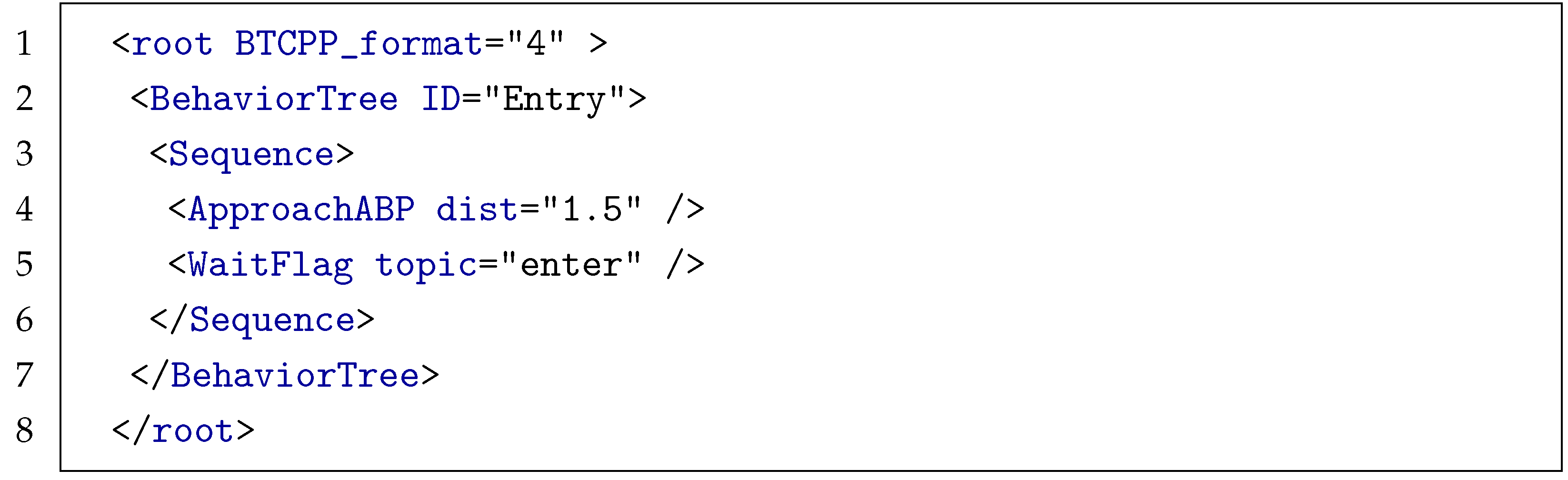
On the one hand, in Listing 2, an example of an Entry behavior can be found. Note that even though this behavior can be seen as simple, the idea is that it can be modified by adding more complex tasks that are able to automate the communication with the infrastructure and the process of approaching the intersection, such as adjusting the speed. Thanks to the possibilities of the operational environment of the behavior engine based on the behavior tree, this can be easily designed and implemented.
| Listing 2. Example of Connection Behavior. |
![Applsci 15 05347 i002]() |
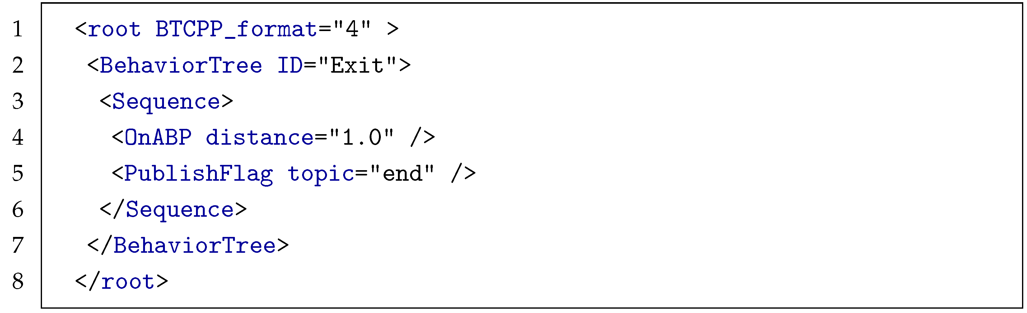
Listing 3, on the other hand, summarizes the behavior related to the Exit ABP placed during the arbitration process to flag when the tracking process will stop. This specific behavior can be adjusted to implement any important activity to develop when Exiting the intersection. Furthermore, as per the fallback directive defined in the Connection Behavior, both Entry and Exit behaviors benefit from the model of execution provided by the behavior tree. This feature makes it possible to define fail-safe actions and implement new strategies in the case of failure, as well as new recommended forms of operations to be executed.
| Listing 3. Example of Connection Behavior. |
![Applsci 15 05347 i003]() |
Furthermore, the selection of compatible
Tracking Nodes occurs at a rate manually defined during the infrastructure container’s execution. This callback takes into account
Tracking Nodes that were already arbitrated and those that are pending to be processed or waiting for entrance. This is important because the compatibility set may change since it is computed in real time, so the callback verifies which
Tracking Nodes in the new set chosen were already arbitrated and which are waiting for it. In
Section 7, this process can be seen depicted with a four-way intersection example and four vehicles requesting arbitration. For the roundabout, the only difference is that the decision whether to place an Entry or Exit point is not based exclusively on compatibility between clusters, but on whether one or more vehicles are detected inside the survey area. From the logical structure of the roundabout, if that scenario happens, the cluster assigned to the vehicle is incompatible by definition; i.e., its survey area contains at least one vehicle treated as a potential threat to a safe entrance. Hence, the arbitration takes place. In the future, the implementation of this interaction, as well as the combination of behaviors and suggestions, is intended to be enhanced by providing a robust mechanism for the system to decide on a vehicle entrance based not only on the usage of the cluster but also on high-level traffic management information like demand and congestion.
6. Resource Optimization
The previous approach relied on complete isolation between control areas represented by Clusters. While this procedure is safe, it is also impractical in reality because vehicles can access these areas concurrently. If an incoming vehicle obtains a Cluster, this resource is locked, forcing other vehicles to wait until the first vehicle leaves, making this system no better than a traffic light and decreasing its capabilities to dynamically assign efficiently managed resources.
To improve the described implementation, a conflict zone optimization based on estimated arrival times (ETAs) is introduced. Hence, instead of blocking entire
Clusters, smaller conflict zones within them are defined. Compatibility is now checked based on the specific
Tracking Node connected, not the entire
Cluster. This approach, inspired by related work on conflict zones and time-based optimization, lays the foundation for a more dynamic system [
50,
51,
52] that does not force a one-to-one relation with clusters and incoming connected cooperative automated vehicles (CCAV). However, for this optimization to take place, several changes to the previous methodology have to be made. First, the tracking process of the vehicle needs to be extended to not only give information about the
Cluster in use but also to provide computation-based information about its trajectory and position inside the
Cluster. For that to happen, the HD Map module is crucial, since the position of the
Tracking Node reported by the connected vehicle will be periodically checked and matched against the Map and the
Cluster Control Areas. This will give the system a dynamic waypoint to localize the vehicle that can be expressed in local, global, and Frenet coordinates for planning and time estimation. This waypoint will be used to construct a set of predictions based on the speed and control commands reported by the connected vehicle.
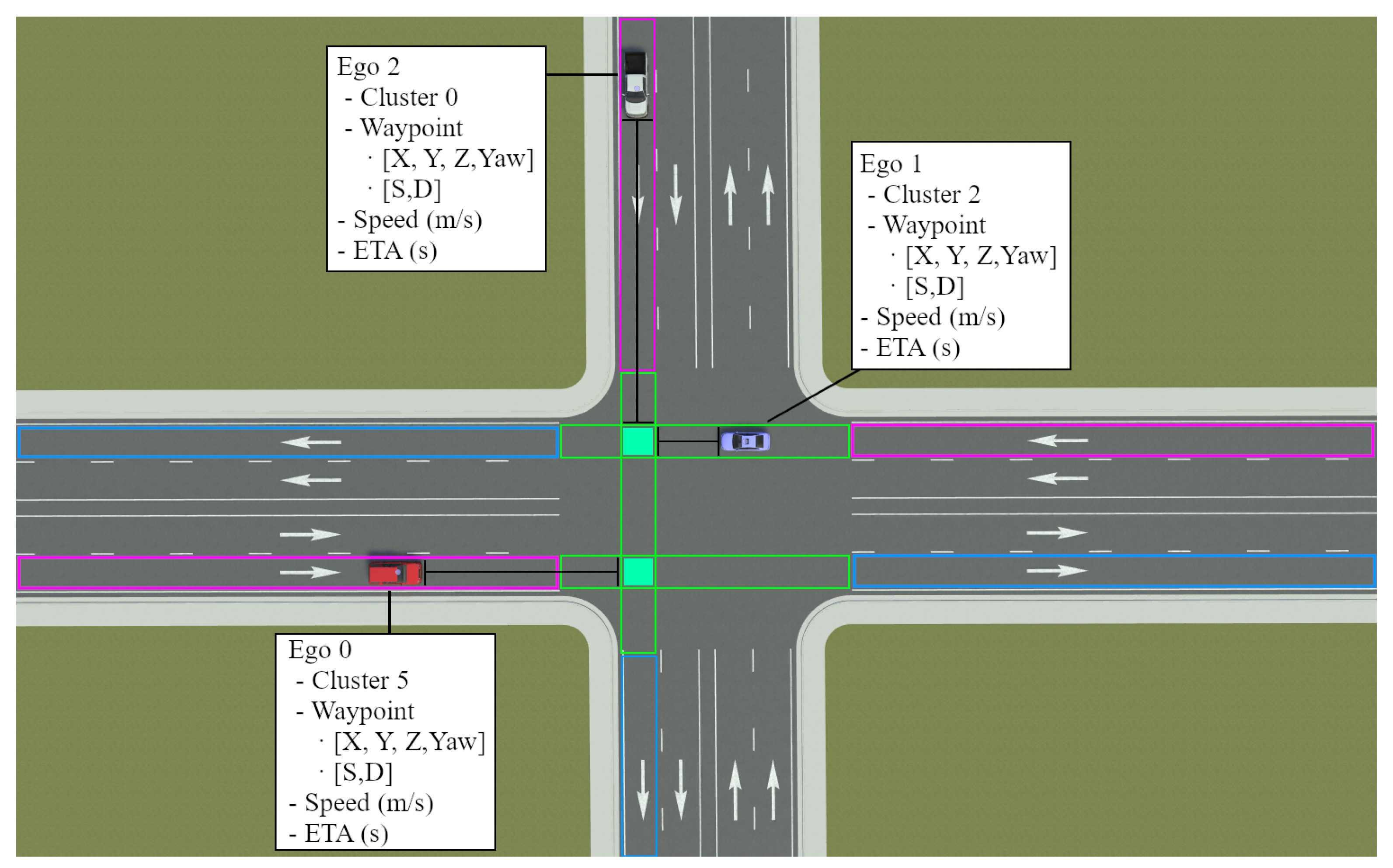
In
Figure 7, this interaction is depicted with three CCAVs approaching a four-way intersection. As can be seen, from the current location of the vehicle, a trajectory is constructed. This trajectory can be computed in several manners. Since this work does not take trajectory predictors into account and the vehicle is automated, the system assumes that the vehicle is going to follow its road plan. Hence, from the local position in map coordinates, a trajectory is constructed following the current cluster lane in which the vehicle reports are to be located. From that lane, the
Control Area length is retrieved, and with the speed the vehicle is reporting, the estimated time of arrival (ETA) is computed. Then, in the callback to select the cluster, instead of comparing
Clusters, the algorithm compares nodes in such a way that to define compatibility, if two vehicles want to share the same conflict zone, a wall time is generated. On the one hand, if the differences between the ETAs of both
Tracking Nodes are less than the assigned wall time, then they are incompatible and cannot be in the same compatibility set. On the other hand, if the system computes the ETAs for both nodes and detects that there is enough time for both to not converge in the same conflict area in the same time window, both nodes are compatible and the entrance is allowed.
Including this methodology within the implementation of the arbitration system, a highly flexible, on demand resource allocation is provided with the real-time processing of current traffic information. Therefore, the final system will make use of more dynamic parameters and constraints to improve the overall flow of the directives provided with the Entry/Exit behaviors.
7. Experimentation and Results
The software ecosystem explained in the previous sections was fully implemented in ROS2 [
26] and tested on Carla Simulator [
27]. The operations between both containers presented are based on ROS2 communication standard with Topics, Services and Actions, and the communication between components for the collaboration uses its Data Distribution Service (DDS) for real-time communication, in which some Quality of Service (QoS) configurable parameters can be adjusted if needed. DDS exhibits inherent compatibility for integration with vehicular communication standards, including ITS-G5 [
53], C-V2X [
54], and 5G-V2X [
55]. Interfacing ROS2 with ITS-G5 necessitates a bridge node (or nodes) for bidirectional translation between ROS2 DDS middleware and the ITS-G5 communication interface. This involves mapping ROS2 messages to ITS-G5 formats and vice versa, publishing parsed ITS-G5 data as ROS2 topics. For specific ITS-G5 hardware, a dedicated ROS2 driver is required to manage low-level hardware communication, exposing data as ROS2 topics/services for higher-level processing and message interpretation.
Furthermore, in order to test the solution proposed, two traffic scenarios are analyzed. On the one hand, the first suggested scenario represents a 4-way intersection in a realistic simulated world where four Cooperative Connected Automated Vehicles converge at similar times at the intersection managed by the infrastructure container previously explained. On the other hand, in the second scenario, a Cooperative Connected Automated Vehicle approaches a roundabout generated in a custom Carla world and lets the intelligent system deployed at its center arbitrate its entrance based on detected threats inside the Survey Clusters.
7.1. Scenario 1—Intersection
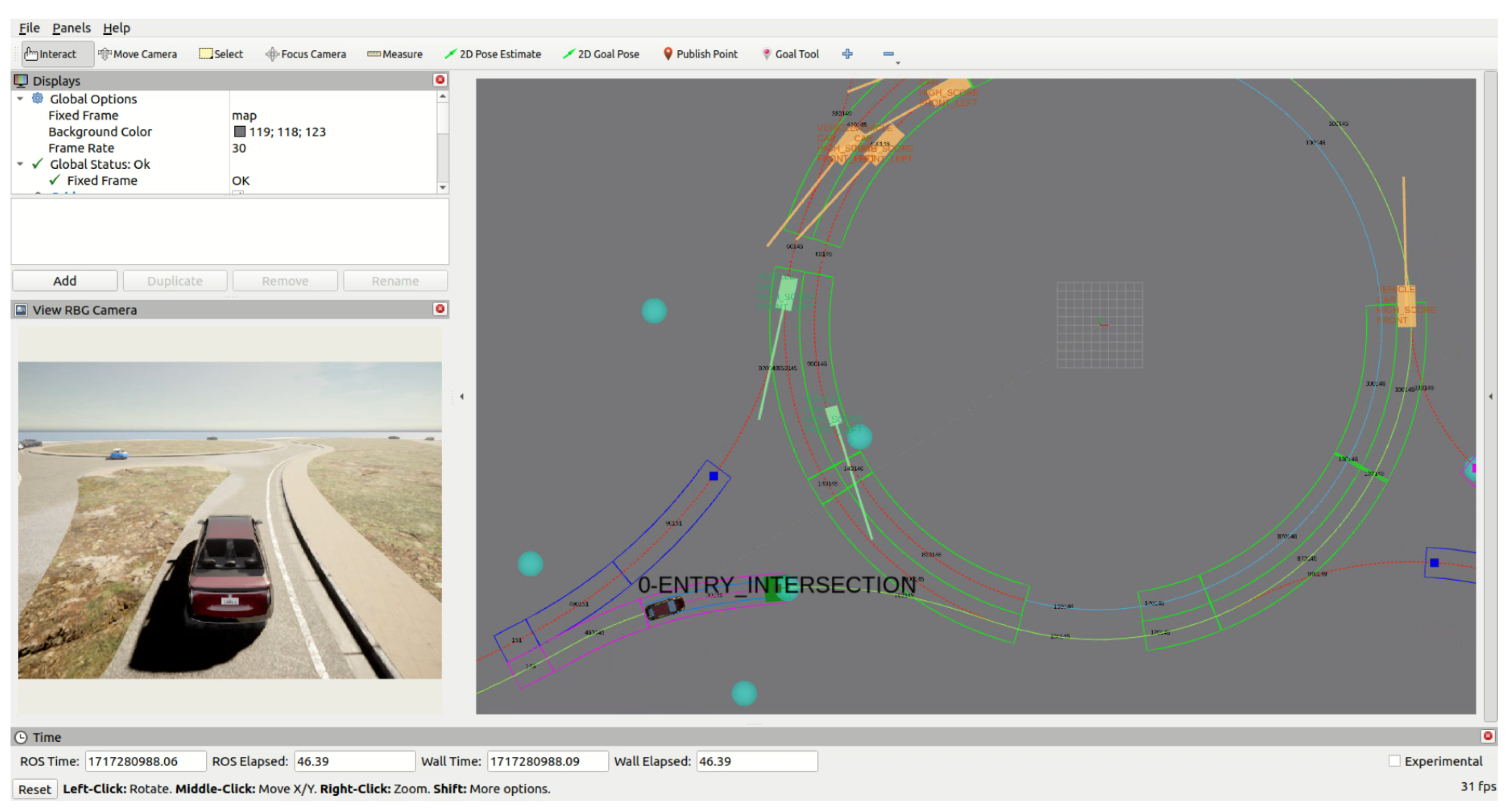
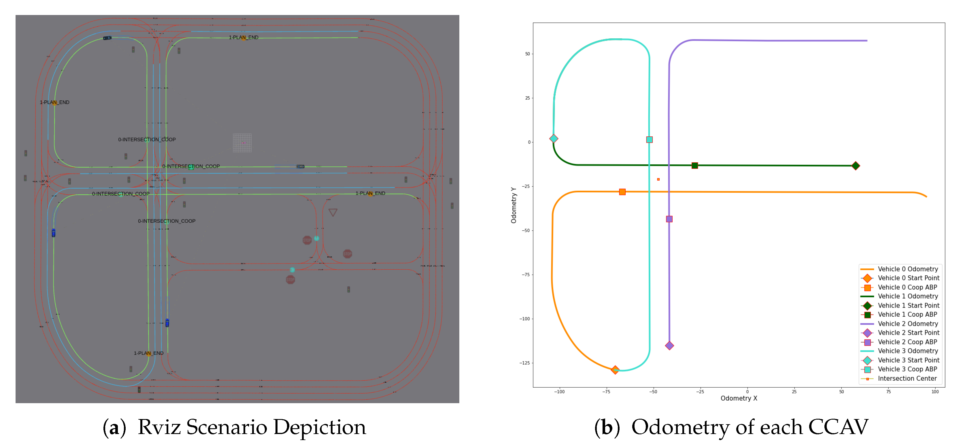
In
Figure 8, the proposed scenario to test the basic functionalities explained in previous sections can be seen (high-definition enlarged figures can be seen in [
56]). This particular experiment focuses on the arbitration of each Cooperative Connected Automated Vehicle when approaching the intelligent intersection. In this case, the system implements the arbitration methodology with the ETA optimization explained in
Section 6. In
Figure 8a, the top-down view display of the ROS visualizer (Rviz) can be seen together with the
Road Plan (Blue and Green lanes), planned ABPs (Orange Circles), and HD Map information (red arrows and landmarks with black digits). On the other hand, in
Figure 8b, the odometry readings for each vehicle recorded during the experimentation are depicted. This odometry comes from the vehicle container localization system based on a Kalman Filter for filtered positioning [
46] using the GNSS and IMU sensors. The expected result of this specific scenario is an automatic management of the Cooperative Connected Automated Vehicles converging with the intersection at similar times.
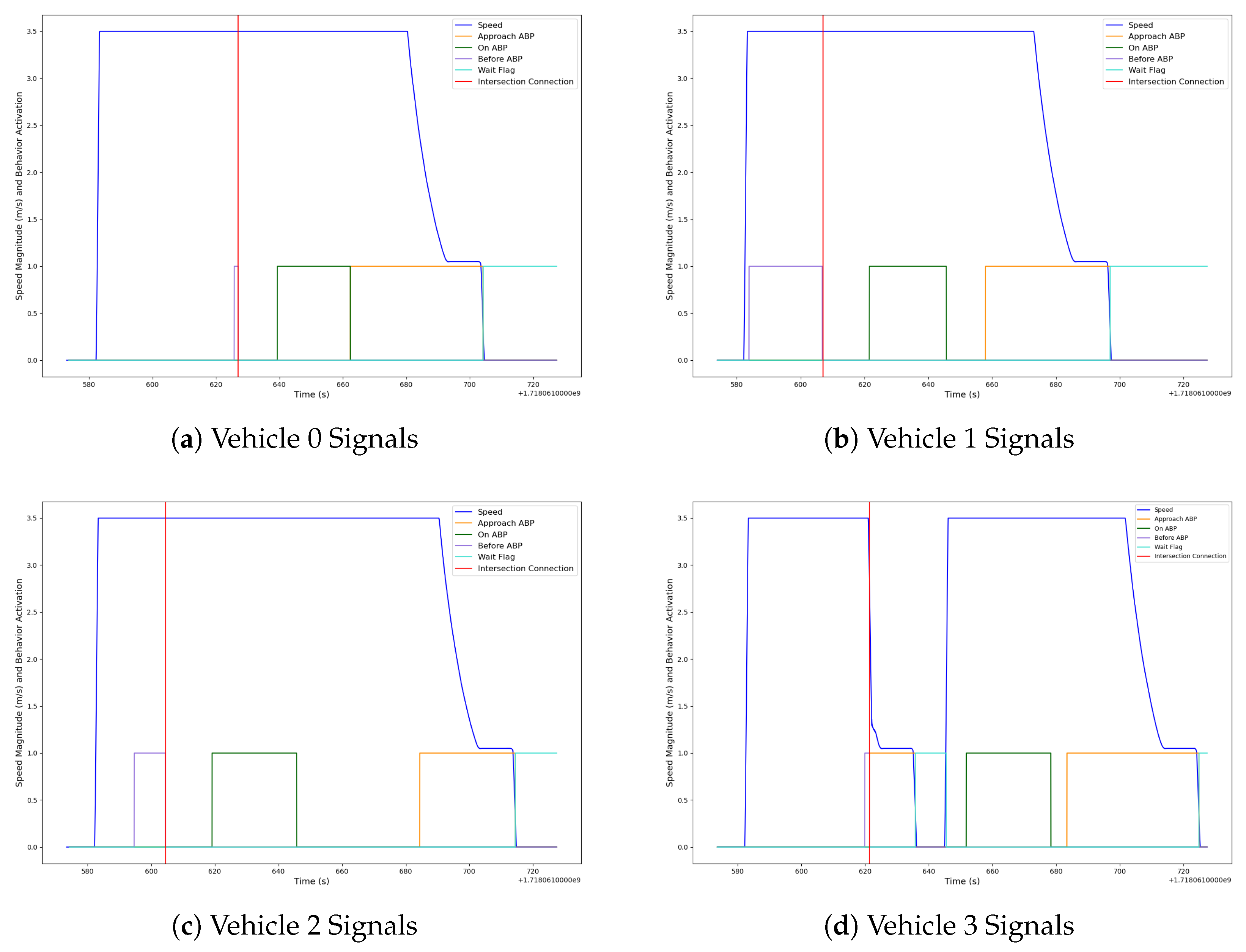
In
Figure 9, the behavior signals activated during the arbitration process, as well as the speed of each CCAV, can be seen. As can be seen, once a connection to the intersection arbitration system is performed, each of the connected vehicles is assigned a
Cluster and updated with a custom behavior deployed in each local mission that adjusts the vehicle with local procedures on how to operate inside the intersection. This behavior would be different depending on the compatibility between the
Clusters assigned and the time predicted for each vehicle to reach the conflict zone tested between each
Tracking Node Cluster. Therefore, each mission will be updated with Entry and/or Exit ABPs in order to arbitrate the entrance between vehicles. Furthermore, since the vehicle’s mission is being tracked, the arbitration system is able to know if the vehicle is approaching or waiting for entrance and if it has already been arbitrated or not. Since this experiment consists of four vehicles converging into the intersection at a similar time, the arbitration system must manage the conflict zones between incoming vehicles to properly give entrance depending on
Cluster compatibility. On the one hand, in
Figure 9d, Vehicle 3 was requested to stop by adding an Entry
ABP to its Mission. On the other hand, the remaining vehicles, shown in
Figure 9a–c, are given free access since the intersection resources are compatible. While the speed of those with free access is maintained, it gradually decreases for Vehicle 3. Then, it is not until the conflict zones are free that the arbitration system releases the waiting flag, effectively allowing entrance to the intersection.
In
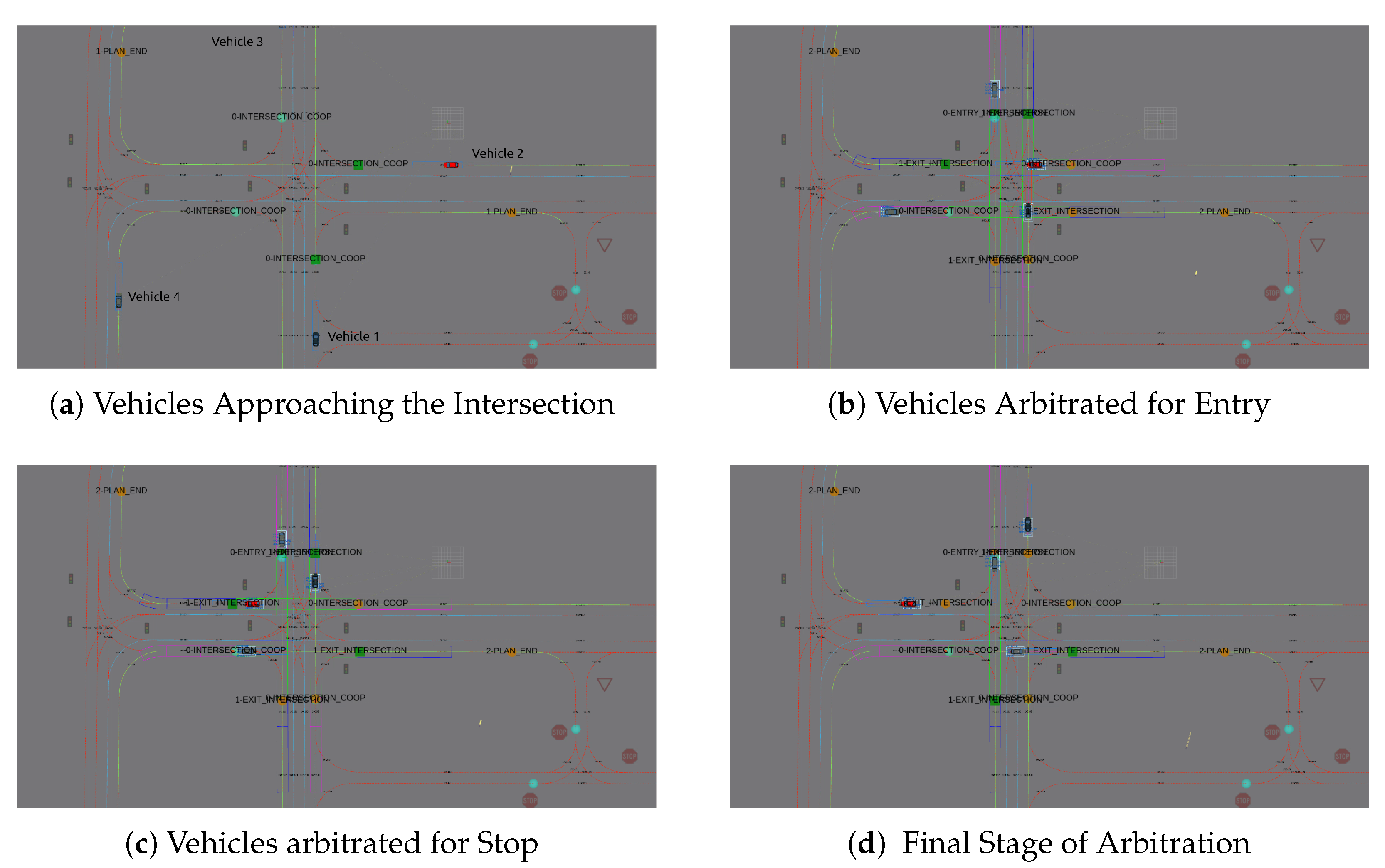
Figure 10, the configuration found in the Carla Server for the intersection arbitration can be seen with the interaction between Cooperative Connected Automated Vehicles and the intelligent Intersection managed.
Figure 10a represents the initial stage of the arbitration, where the vehicles were approximating the intersection, and then
Figure 10b,c depict how some vehicles are marked for entrance and others for stopping. Finally,
Figure 10d represents the final stage of the arbitration process, where the waiting vehicle in this case is given free entrance after the other vehicles leave their respective conflict zones. Once every vehicle leaves the intersection, the tracking process stops and waits for new incoming request connections. Note the Exit
ABPs placed by the
Intersection Manager to release the resource usage once the tracked vehicle leaves. This is carried out with a flag that is connected from the vehicle to the infrastructure container, published once the vehicle finishes the
Exit ABP, in which a task of publishing the release flag is implemented as part of the behavior associated with that
ABP.
Note that each vehicle follows independent trajectories and road plans that are locally managed by the mission and planning system deployed in each vehicle container. During this process, the infrastructure container is able to coordinate actions between incoming connected vehicles and organize through a centralized method the way this vehicles interact with the environment. In
Table 2, a comparison between the methodologies proposed can be seen with the average waiting time for each CCAV approaching the intersection and the average idle time of the emplacement, specifically when no vehicle occupies it. This comparison used a base case of a traffic light model controlled by the Carla Simulated intersection.
7.2. Scenario 2—Roundabout
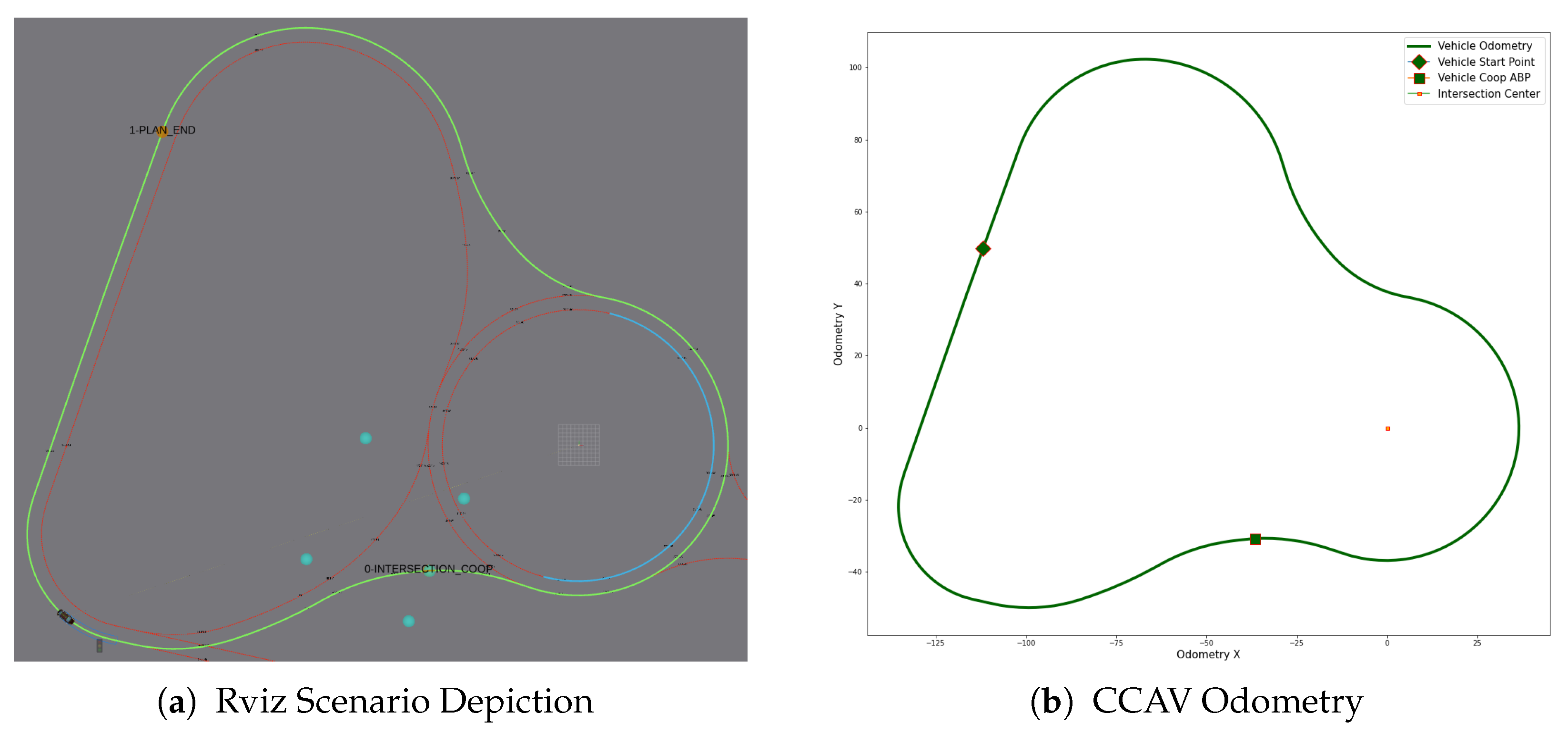
In
Figure 11, the proposed scenario to test the basic functionalities for the roundabout arbitration can be seen.
This experiment is focused on the arbitration at the roundabout of the Cooperative Connected Automated Vehicle that needs to traverse a roundabout when following the
Road Plan given. In this case, the system implements the arbitration methodology applied to the roundabout surveillance area concept discussed in
Section 5. Similar to the other experiment, in
Figure 11a, the top-down view display of the ROS visualizer (Rviz) can be seen with the
Road Plan (Blue and Green lanes), ABPs (Orange Circles), and HD Map information (Red arrows and landmarks). On the other hand, in
Figure 11b, the odometry readings for each vehicle recorded during the experimentation are depicted.
The expected result of this experimental scenario is a fully automatic approach to the roundabout in which the vehicle, once connected to the infrastructure, is requested with a mission update depending on the status of the cluster assigned. In
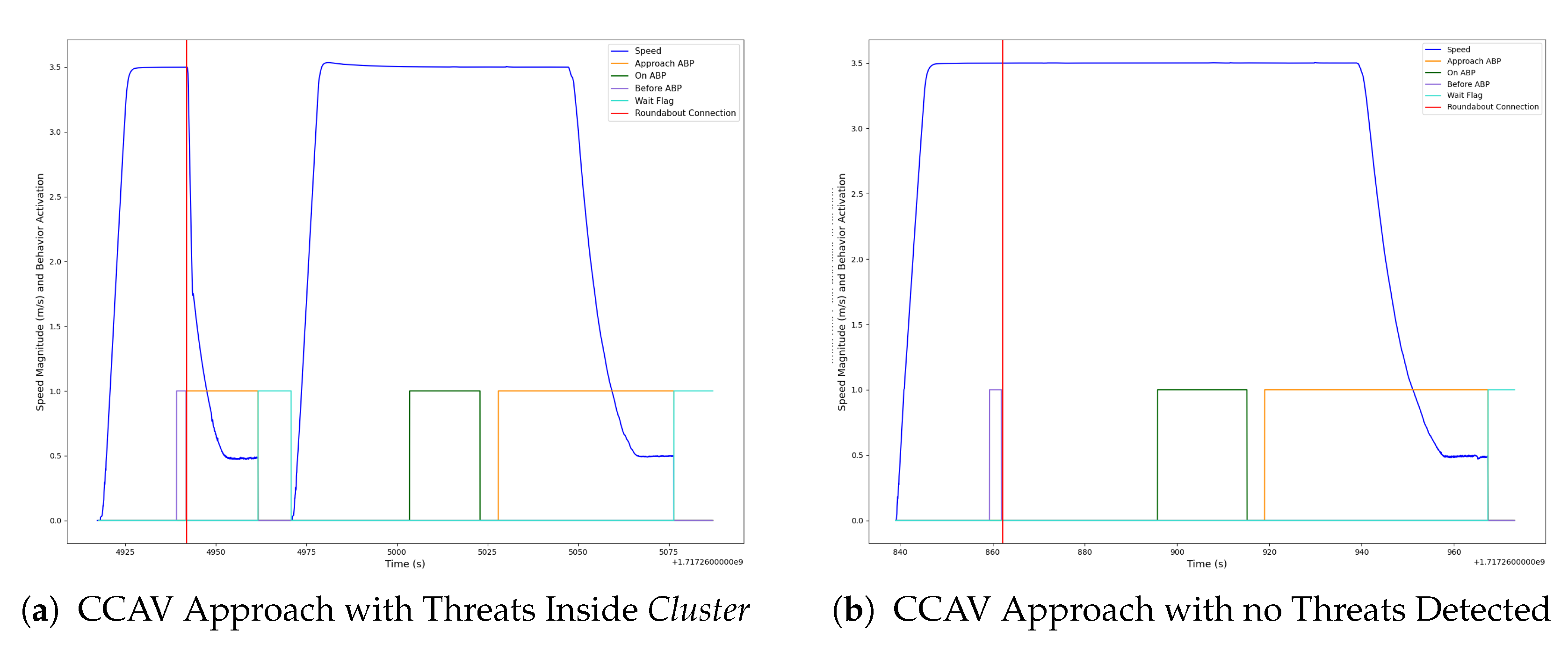
Figure 12, the speed of the vehicle when approaching the roundabout, as well as the behavior activation flags, can be seen. In
Figure 12a, the vehicle is tracking an ABP of a connection, and when the
BeforeABP action is finished, the
RequestConnection is triggered. Once this action finishes, it returns successfully and assigns a
Cluster to the vehicle. The cluster managed by the infrastructure container detects a threat inside the survey area and requests that the vehicle stops updating its mission with an Entry ABP (
ApproachABP and
WaitFlag actions). Once the vehicle stops at the ABP and the infrastructure container detects no threats inside the surveillance area of the cluster assigned, the stop flag is released allowing the vehicle to go inside the roundabout. Then, the Exit point is reached and stops the tracking process by finishing the action (OnABP). On the other hand, in
Figure 12b, the scenario in which the infrastructure container does not detect a threat inside the area and provides the Cooperative Connected Automated Vehicle with a free course mission can be seen.
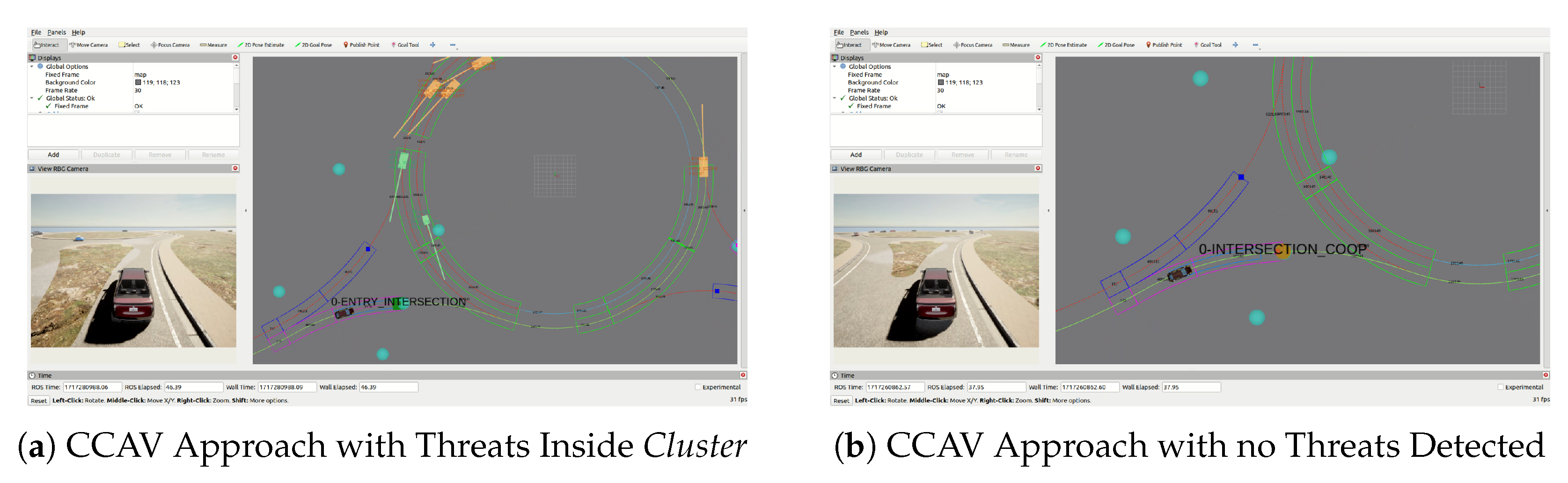
In
Figure 13, the configuration found in Carla Server for each roundabout scenario can be seen, showing the behavior when a stop is needed and when the vehicle has free access to the roundabout.
Figure 13a represents the approach when the Cluster was assigned and a threat was detected, forcing the vehicle to stop at the Entry point with an Entry
ABP. On the other hand,
Figure 13b shows the scenario in which the Cooperative Connected Automated Vehicle was able to go inside the roundabout since no threat was detected, and no Entry ABP was placed by the arbitration system.
As can be seen, the outcome of this arbitration process exhibits a distinct nature compared to intersection management. The roundabout system employs a more centralized architecture, enabling global resource allocation for roadway utilization. Furthermore, this system is designed to accommodate mixed traffic scenarios, incorporating a perception subsystem that tracks non-arbitrated vehicles within the circulatory roadway for incompatibility detection. The inherent geometric configuration of the roundabout presents several challenges; specifically, the precise Entry angles and lane configurations are critical for effective cluster generation and subsequent arbitration. The operational efficiency of a roundabout is typically contingent upon balanced traffic demand across all approaches. Consequently, incompatibility assessments consider all vehicles both within and approaching the roundabout over an extended temporal horizon. Moreover, roundabouts generally feature a reduced number of conflict points and lower operating speeds. In contrast to intersections, pedestrian actors are typically not involved, simplifying the conflict resolution process. Finally, the capacity of a roundabout is largely determined by its initial physical design, rendering virtual construction and capacity analysis more complex.
7.3. Increasing the Number of Agents
The experimental evaluation revealed a constraint on the maximum number of concurrent simulated agents. Given the actor-based architecture, where each vehicle container, governed by the framework detailed in [
31], is simulated independently, the current hardware configuration limits the system to four to six concurrent vehicles. For the sake of clarity, at most four CCAVs are used in the experimentation phase to present the signal graphs. Ideally, each vehicle container would be deployed on a dedicated machine networked with the simulation server to ensure automated control, particularly as cooperative modules are integrated within each actor and need to be tested as well. However, the present setup, constrained by hardware availability, involves a multi-agent simulation executed on a single server, which manages both the simulation environment and the simulated CCAVs, alongside the internal processing of vehicle and infrastructure containers. Consequently, the computational resources to enhance the fidelity and scalability of the arbitration implementation should be increased accordingly to test the solution with different traffic densities. Experiential measurements of this impact reveal that each simulated vehicle increases CPU usage by approximately 10%, GPU usage by approximately 15%, and RAM memory usage by roughly 1 GB. Consequently, the simulation achieves 30 FPS with four vehicles but drops below 10 FPS with more than six, directly impacting its stability and indicating a scalability limitation for future iterations.
Furthermore, empirical evaluation indicates a performance disparity in the Carla simulator, exhibiting lower frame rates on Linux systems compared to Windows. A major factor is believed to be the poor performance of NVIDIA’s Linux drivers in rendering tasks when compared with Windows drivers. For future iterations, current investigations are exploring a distributed simulation architecture, deploying the Carla Server on a Windows instance while concurrently connecting Linux-based clients running the ROS.
8. Discussion
After the explanation of the solution proposed for traffic arbitration based on behavioral collaboration and the experimentation carried out, some important comments must be made.
The solution presented in this work is a basic foundation to represent the possibilities of future arbitration systems that aim to harmonize the interaction between connected traffic agents. The implementation of the idea proved to be valid with an improvement in the waiting time of each managed vehicle and the average idle time of the emplacement. The system focuses on the management of several CCAVs under the same ecosystem and their arbitration in two different traffic topologies, intersections and roundabouts, showing modular and flexible capacities. Finally, the framework presented provides a full ecosystem of well-defined responsibilities for the cooperation of the Intelligent Transportation System powered by the ROS middleware framework and validated in the Carla simulator.
Nevertheless, there are still problems to be faced, mostly in the field of vehicular networks and agent communications and also in multi-agent simulation and resource optimization. More testing is needed, and a better and optimized simulation framework for the simulation of real traffic demand that operates under the software container explained is vital for the system to work properly. However, this is a step forward in the generation of an effective framework for arbitration that does not necessarily have to count on the automatic nature of the vehicle. Although one of the main disadvantages of the solution proposed is that it assumes the vehicle requesting the connection is fully automated, in reality, mixed traffic can exist, and the arbitration system should take into account vehicles not operated automatically, as well as pedestrian crossings. In order to carry that out, the proposed system necessitates a holistic architecture addressing safety, efficiency, and intricate vehicle–pedestrian interactions. A dedicated Pedestrian Intention Prediction module, leveraging machine learning models trained on kinematic data (gait, direction, velocity) and spatial context (proximity to crosswalks), is crucial for anticipating pedestrian behavior beyond mere detection. Moreover, prioritizing safety, the arbitration logic must implement a preemptive safety response for any potential pedestrian conflict. Furthermore, the system shall integrate real-time pedestrian signal state awareness, mandating CCAVs to yield upon detection of an active pedestrian signal. These functionalities will be encapsulated within a dedicated Pedestrian Handling Module, integrated into the core arbitration software, responsible for processing pedestrian-centric data and generating corresponding control actions.
Furthermore, the selection cost function should be refined, taking into account traffic forecasting parameters to enhance the overall performance of the process. This cost function should incorporate several key features, such as Time-to-Collision (TTC) within defined conflict zones, employing a critical safety threshold; a delay metric computed based on predicted and current waiting times, the cumulative number of stops since arbitration initiation, and the estimated plan execution time. The cardinality of compatible cluster assignments at each time step also has to be considered to maximize resource utilization. Furthermore, the presence of pedestrian crossings and detected pedestrian agents constitutes a critical term in the decision-making process. Finally, the cost shall be modulated by vehicle type, encompassing size and category, to accommodate specific behaviors for emergency vehicles, heavy good vehicles, and standard passenger vehicles. Hence, new implementations should consider these features while the technology evolves and more mature and robust automated systems are constructed.
Finally, it is pertinent to address limitations within the simulation environment that directly influenced the experimentation phase. The current research implementation exhibits a constraint of approximately four to six concurrently simulated vehicular agents, with performance degradation to a low number of frames per second (FPSs) observed at the upper limit of this range (i.e., six vehicles). Future iterations will necessitate a focus on enhancing the scalability of the simulation to accommodate diverse traffic typologies and densities, thereby enabling more robust performance evaluation of the proposed framework. While the computational demands of the CARLA simulator are substantial, potential mitigation strategies include server clusterization and driver-level optimizations.
9. Conclusions and Future Work
In this work, a centralized arbitration system is presented based on behavioral collaboration and multi-agent communication. The idea was implemented on an ROS2 open-source framework and tested on Carla simulator for realistic experimentation. The proposed architecture demonstrated sufficient performance for real-time arbitration in complex traffic environments, making use of fully automated vehicle systems with cooperative capabilities, decreasing the average waiting time in simulated intersection scenarios by 13% and increasing the total utilization of the traffic emplacement by 70% compared to the classic traffic light model. These results are presented taking into account the current simulation test-bed limitations and with at most four CCAVs. Future research will integrate these results as a baseline for framework improvements and enhancement with diverse traffic densities.
Furthermore, the proposed framework incorporates inherent extensibility to readily accommodate future implementation requirements and leverage emerging advancements. The framework’s modular architecture facilitates the development and seamless integration of novel modules, thereby enhancing system capabilities and enabling operation within increasingly complex traffic environments incorporating pedestrian dynamics. For instance, the integration of a dedicated pedestrian prediction module will augment the system’s perceptive and decision-making capacity in scenarios involving crossings. Moreover, the idea of behavior collaboration provides the flexibility to adjust the way CCAVs operate under certain traffic emplacements, potentially decreasing the amount of waiting time, improving traffic prediction, and mitigating congestion that may occur in modern cities. The dynamic nature of the ABP concept allows for adaptive responses that are able to adjust to the current context in a clear and transparent way. And, while the system is in a preliminary phase, it provides a basic foundational framework from which to modulate the available collaborative aspects of a vehicle, conceivably enabling a better driving experience.
Although the proposed system focused on Entry and Exit waypoints where a specific behavior is defined, for future works, this idea can be extended to be more dynamic in nature, allowing the behavior itself to be adjusted depending on the information shared among the traffic agents. This can mean small arbitration instances of trajectory optimization, speed/acceleration modulation, and, of course, Entry flag management to dynamically modulate the usage of resources. Hence, by employing fine-grained control strategies (control mechanisms that allow for a very precise and detailed level of influence or management over a system or process) over traffic infrastructure through atomic behavior primitives (the most fundamental, indivisible units of actions inside an ABP that an automated vehicle can execute), the system enhances traffic flow by minimizing non-essential stops. Instead of coarse-grained Entry and Exit behaviors, the system would implement sophisticated strategies that dynamically adjust lane assignments, localized speeds, and trajectories for optimized traffic management. Furthermore, for mixed traffic scenarios, the proposed system can incorporate a human–machine interface (HMI) to provide guidance to human drivers. This HMI, utilizing modalities such as visual, auditory, or non-invasive haptic feedback, would convey optimal driving actions within the managed intersection or roundabout. This approach would extend the system’s real-time computations beyond internal control, disseminating actionable information to cooperative vehicles via the HMI.
Finally, further empirical validation is required across a broader spectrum of traffic conditions, particularly those involving high-velocity ingress. This also implies the generation of increased simulated traffic volume, also controlled in parallel by each vehicle container, for comprehensive throughput and interaction analysis under high-density conditions. To achieve this, the multi-agent simulation environment will require optimization adjustments and deployment on high-performance computing hardware. Nevertheless, the important fact is that, thanks to the modularity of the implementation, the system explained is expected to evolve when new needs and requirements are encountered, therefore providing new capabilities and enhanced tracking and optimization systems that will develop as new technology emerges.


 ,
, 


