1. Introduction
With the development of technology in hard-to-access locations such as wind turbines, the development of a self-sufficient lubrication system is more relevant than ever. The bearing discussed here is a self-circulating bearing that would allow the initial charge of fluid to the system to lubricate the bearing throughout its life without the need for an external pumping system.
The technology for this self-contained, independent fluid system comprises a fluid journal bearing with a porous bushing surrounded by a fluid reservoir, where the pressure differences in the passive reservoir circulate fluid into and out of the bearing clearance [
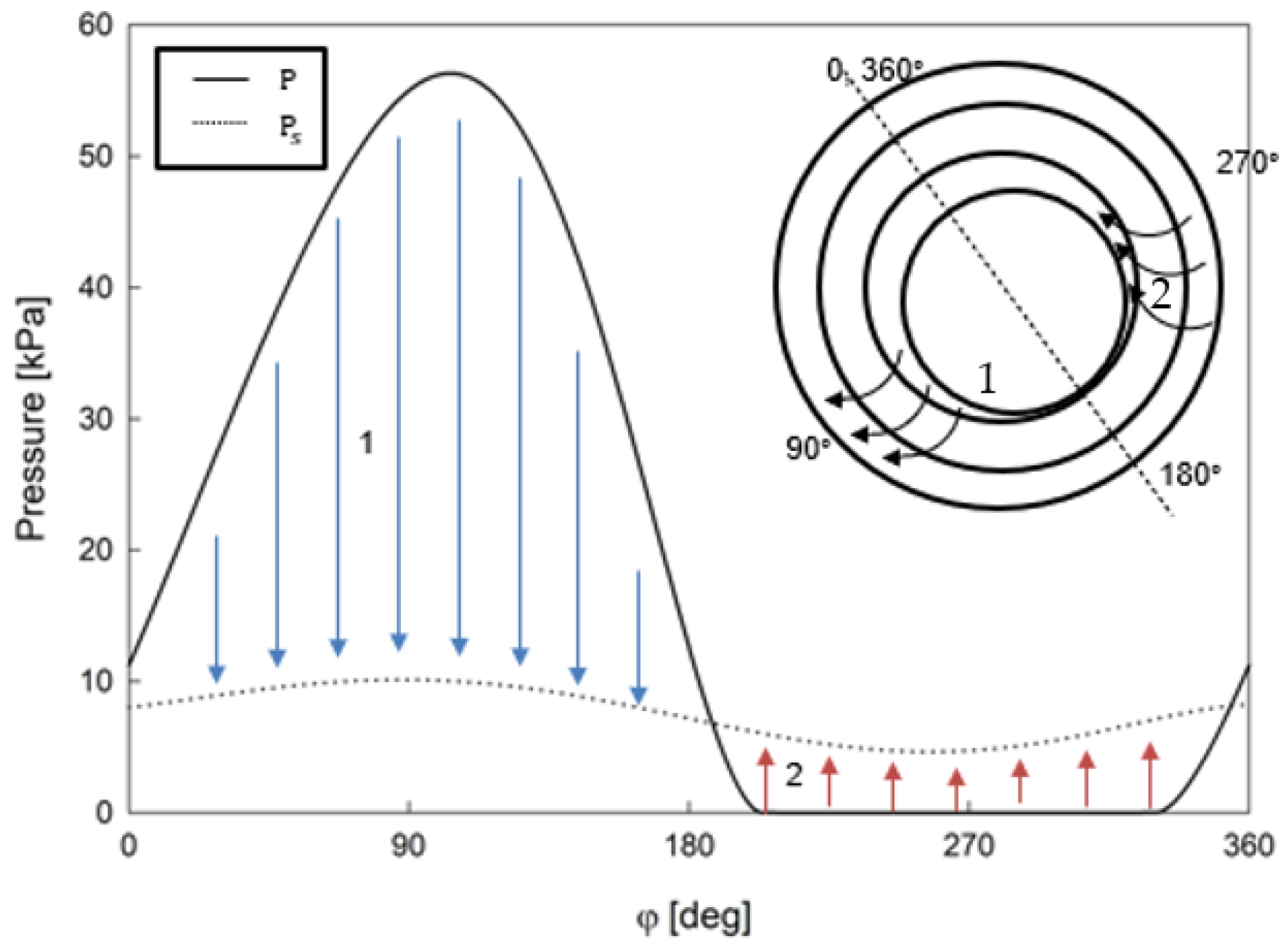
1]. As in typical fluid journal bearings, there is a shaft surrounded by a fluid film. The fluid film has a convergent section, where the fluid pressure increases until the position of minimum clearance (section 1 in
Figure 1). Continuing counterclockwise around the bearing, the divergent portion of the bearing continues until the position of maximum clearance in the bearing with decreasing fluid film pressure (section 2 of
Figure 1). The fluid film is surrounded by a porous bushing, as opposed to a solid bushing in a standard fluid journal bearing. Surrounding the porous bushing is a passive reservoir of fluid that is initially charged to a specified pressure. The passive reservoir is bounded by a solid casing to keep the fluid contained. The numerical model presented here is the first step towards having a custom numerical model of a self-circulating bearing that will allow for the study of the bearing’s characteristics and limitations.
Numerical modeling would enable designers to design the bearing more efficiently and to understand the factors that affect the bearing’s performance. Porous journal bearing modeling is a mature field, with the current investigations focused on improving numerical models alongside explorations into enhancing bearing performance. As detailed below, researchers have relied upon simplifications to solve the complexities of porous journal bearing modeling. The numerical approach presented herein is a novel closed-form solution that improves computational speed and effort, offering the opportunity to predict three-dimensional behaviors within the porous bushing. This information will improve the predictions on the bearing stability during operation.
While the technology discussed here differs from a porous journal bearing, there are shared characteristics; therefore, a brief overview of the current porous bearing technology is warranted. The initial porous journal bearing numerical models started with limitations for either short or long journal bearings [
2,
3,
4,
5,
6]. Once finite bearings became standard, the boundary condition between the fluid film and porous bushing became a point of interest [
6,
7,
8,
9,
10]. The three-dimensional representation of the porous bushing was the next phase of improvement in the late 1990s, which utilized various boundary conditions at the external ends of the bushing to simplify the problem for a numerical solution [
3,
11,
12]. More recently, investigators have focused on incorporating nanoparticles within lubricants to increase viscosity and thus bearing load capacity [
13,
14]. Textured porous bearings have also been an area of focus for reducing friction and enhancing performance [
15,
16,
17].
Johnston et al. were the first to attempt to model the fluid reservoir surrounding a porous slider bearing [
18]. Balasoiu et al. continued modeling the bearing, expanding it to a 3D cylindrical geometry in commercial software, which focused on reservoir depths and their effect on the self-circulating system [
19]. The different physics between a slider and journal bearing prohibited this work from being built upon in the current paper, as was warned by the authors [
18].
Another adjacent technology that should be discussed is that of porous air bearings. Some authors have numerically modeled these bearings with a constant supply of air surrounding the bushing, which is reminiscent of the reservoir of the self-circulating bearing. Lee applied this constant air as a constant pressure boundary condition at the edge of the porous bushing [
20]. Lee’s work was validated with previous experimental work by Majumdar who had prohibited side leakage from the porous bushing [
21].
The presented closed-form solution for three-dimensional flow within the porous bushing improved on the fluid characteristics within the bearing, the injection velocity prediction entering the bearing clearance, and the circulation estimation within the passive reservoir. While the current study does not account for multigrade fluids, the fluid properties within the custom code are adaptable to these conditions. Future upgrades to the model could entertain the texture of the porous bushing, although the current version does allow users to change the homogeneous permeability to account for some of these effects. The foundation presented here creates an opportunity to include these upgraded properties and account for cavitation and energy transfer within the bearing. It will also be compatible with the dynamic analysis of the stiffness and damping within the bearing, although steady-state conclusions are the focus of this work.
2. Methods
A self-circulating bearing utilizes the natural pressure variation within the bearing clearance to drive fluid through the porous bushing and into the passive reservoir. This process is reversed in the divergent portion of the bearing, where fluid flows into the bearing clearance (
Figure 1). This recirculation prevents the need for an external pumping system and serves to prevent vaporous cavitation as the fluid flows through the natural heat sink of the porous bushing. The focus of the results presented here is to emphasize the improvements achieved through a closed-form solution for the three-dimensional bushing. While there are many studies that could be performed with the model, the trends for this type of bearing, computational time saved, and the improved accuracy for the pressure distribution within the bushing will be the focus.
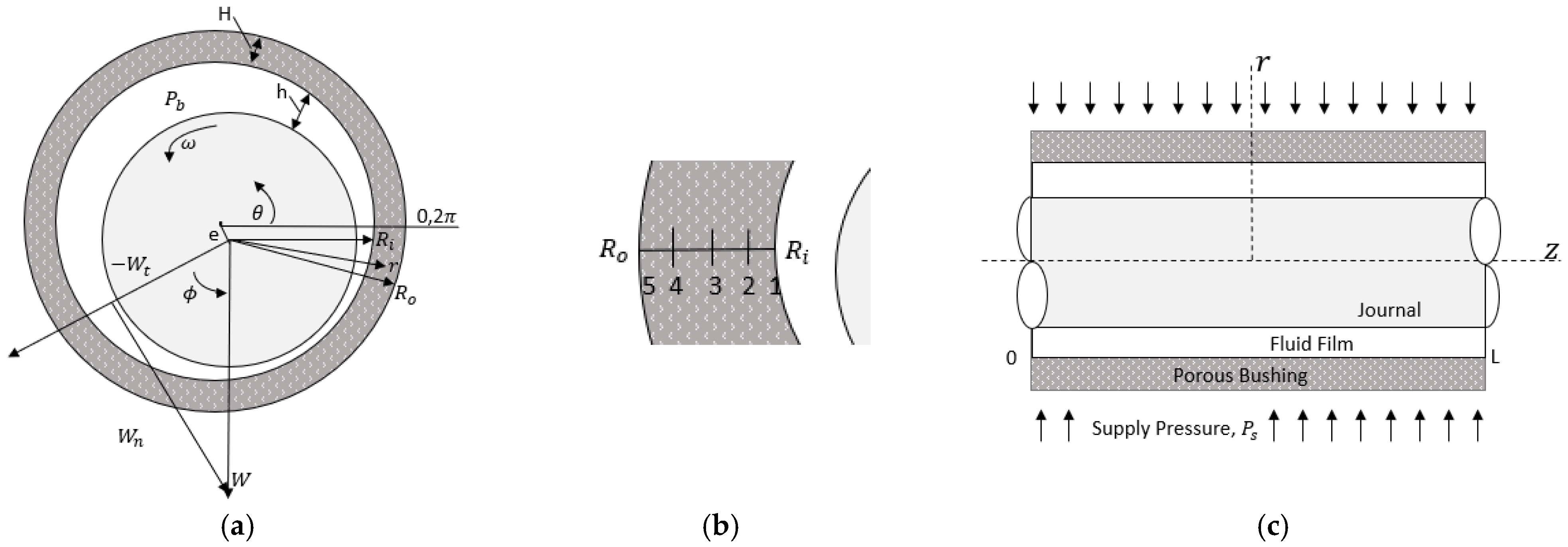
The fluid film in the journal bearing, as shown in
Figure 1, was modeled using the Reynolds equation [
22].
The bearing eccentricity ratio—the bearing eccentricity divided by the clearance of the bearing—describes the displacement of the journal’s axis of rotation relative to the bearing’s center. This controls the fluid film thickness,
, as expressed in the following:
The permeability of the porous bushing,
, and the pressure difference within the porous bushing radially were used in Darcy’s law to represent the injection velocity from the porous bushing into the bearing clearance.
The working form of the Reynolds equation used Equation (4) to define the injection velocity.
The pressure gradient in the porous bearing at the fluid–bushing interface was computed using a second order forward derivative, with
, as in
Figure 2b.
where
is the pressure at axial and circumferential locations on the porous medium–fluid film boundary; referenced as the bearing pressure,
, below. This contrasts the numerical simplifications of the previous works that assumed the porous medium had a linear pressure distribution, where the pressure was calculated as the linear slope between the inner and outer radius of the porous medium [
23]. The calculation of the pressure slope at each circumferential location improved the accuracy of the injection velocity (Equation (4)). The grid used within the porous bushing was verified using a convergence study on denser grids in the radial direction.
Periodic boundary conditions were used in the circumferential direction while the axial ends of the bearing were exposed to atmospheric pressure. The boundary between the porous media and the fluid film was a no-slip boundary condition, with the pressures in the fluid film equal to the pressure in the porous media at the boundary.
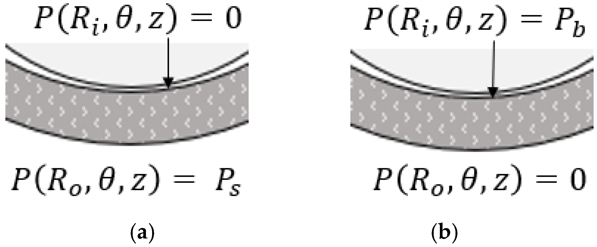
The flow within the porous media was assumed to be isotropic, and the oil was assumed to be incompressible, allowing the 3D Laplace equation—neglecting inertia—to represent the flow within the porous bushing, as shown in Equation (7). A change in variable subtracted atmospheric pressure from all pressures. Then, a superposition solution was imposed with a split of the radial boundary conditions into two ‘problems’ to enable the response of pressure to each boundary condition to be considered one at a time, while the other boundary was set to a homogeneous boundary condition. The ‘first problem’ imposed the lubricant supply pressure boundary condition, while the ‘second problem’ imposed a boundary condition equation with the bearing pressure as the pressure at the fluid film–porous interface.
Each of these ‘problems’ was solved with a product solution. The ‘first problem’ used the pressure along the outer radius of the porous medium that was equal to the supply pressure, with the inner radius pressure set to zero. The ‘second problem’ used the pressure of the bearing, found from the modified Reynolds equation as the boundary condition along the inner radius of the porous medium, while the pressure along the outside radius was set to zero. The separation of variables was used to ensure a homogeneous boundary condition in each scenario, which greatly simplified the solution and allowed for a closed-form solution.
When the boundary conditions as shown in
Figure 3 were applied to the separated pressure distribution, a closed-form solution for the pressure at each radial, circumferential, and axial location was obtained. The solution used Bessel solutions in the axial and circumferential directions and the expansion of the trigonometric integrals to solve the constants, as detailed in Clifford’s dissertation [
21].
Equations (8)–(8c) were calculated after each iteration of the modified Reynolds equation, Equation (5), using the new bearing pressure for the boundary condition in the ‘second problem’. The first term of Equation (8) solves the ‘first problem’; the remaining terms solved the ‘second problem’ [
21]. The analytical solution for the pressure was used in the three inner layers of the porous media journal, as shown in
Figure 2b.
The passive reservoir was simplified for the current model. The reservoir pressure was not updated with each iteration of fluid within the porous bushing but instead held to a representative pressure distribution correlating with experimental results [
19].
The fluid film between the shaft and the porous media bushing was modeled as an unwrapped bearing using a finite difference method with one radial grid, 200 divisions in the circumferential direction, and 60 divisions in the axial direction. This unwrapped grid was applied at each of the three inner layers of the porous medium. The supply pressure from the passive reservoir’s representative equation was applied at each grid location. A convergence study for the selected grid size was performed to confirm that it was adequate. For stability and the ability to use larger time steps, the implicit discretization of the Reynolds equation was used. Numerical stability was achieved for the parameters used; however, if the injection velocity magnitudes were too large, instabilities could occur. One method to prevent this would be to lower the relaxation coefficient; however, this is only valid for a steady-state solution, as it disrupts the time step.
The steady-state solution was obtained once the pressure solution converged below 0.1% for the error criterion, which was obtained using Equation (9). The loads in the radial and tangential direction were determined with Equations (10) and (11), and the bearing load and attitude angle were calculated using Equations (12) and (13).
The feeding parameter, Equation (14), was used for a comparison of the results. A larger feeding parameter implies a large injection velocity. The feeding parameter can be modified by either the porous medium permeability or the porous medium thickness,
H.
3. Results and Discussion
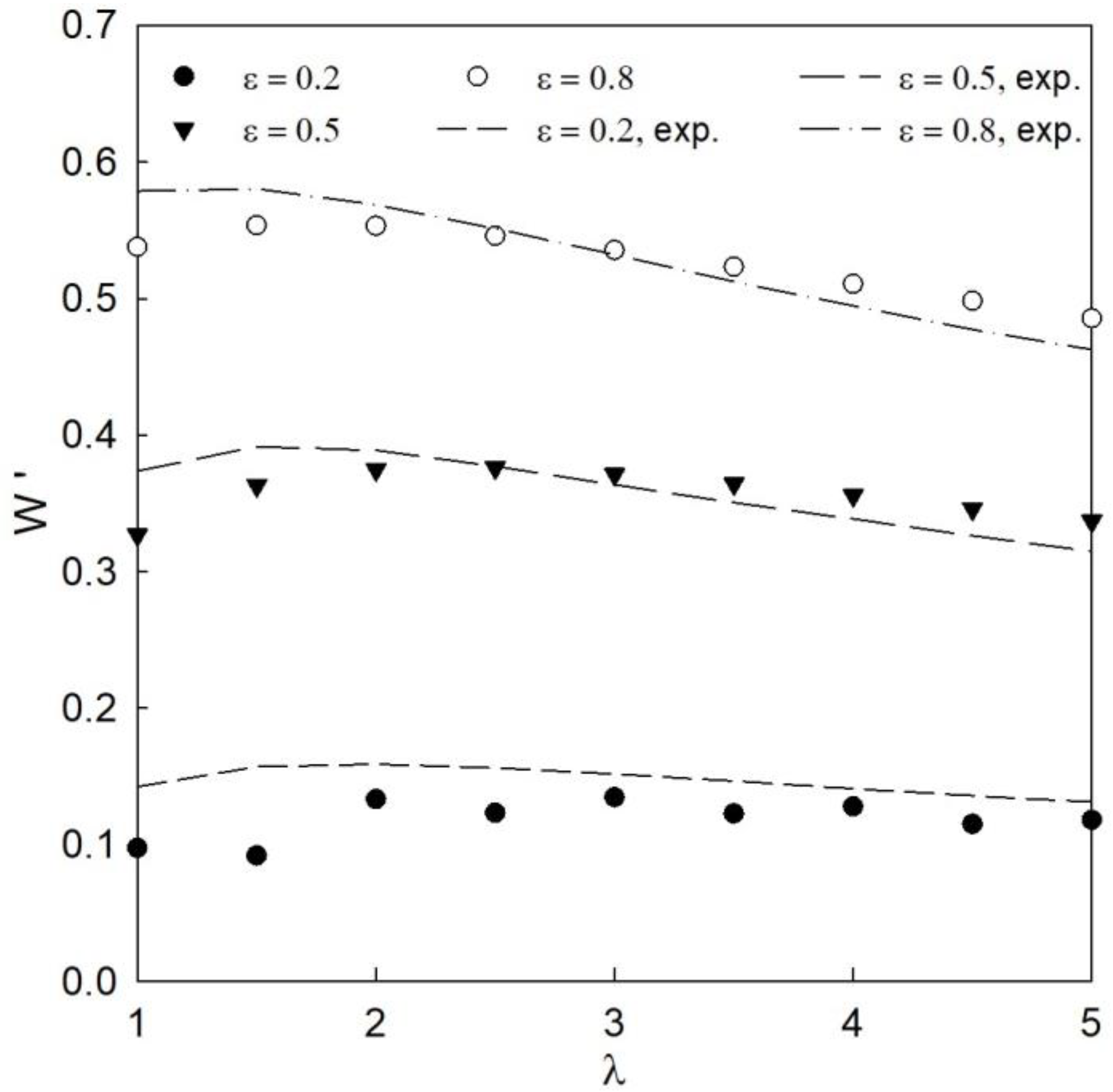
The validity of the present computational solution was verified and is illustrated in
Figure 4 across a range of eccentricity ratios. Verification was completed using air as the working fluid to prevent error from cavitation not included in this model. As in Lee’s work [
20], the ideal gas law was used with Darcy’s law governing the injection of air into the bearing from the porous medium. Excellent agreement was shown between the present work and that of Majumdar using the geometry, characteristics, and fluid of the previous work [
24]. The variance in results stems from the different axial boundary conditions used in the simulation. The current work used a Dirichlet boundary approach condition in which the edges of the bearing were equal to atmospheric pressure [
19], while the referenced work had set the axial direction pressure gradient equal to zero. The previous work limited the feeding parameters that were explored. The current work expanded this range and revealed trends that were not previously investigated.
For the remainder of the results, a finite length porous bearing with L/R = 1, c/r = 0.001, and h/D = 0.1 was analyzed at moderate speed (5000 rpm) and room temperature, 72 °F. Properties of VG-32 oil were used for the lubricant with a Gumbel cavitation model. The range of permeabilities resulted in a feeding parameter spanning 4.55 to 455, where each change in permeability resulted in an order of magnitude change in the feeding parameter (Equation (14)). The supply pressure surrounding the porous bearing had a constant pressure of Pa. The density and viscosity were held constant throughout the analysis. For validation and results, the coupled solution converged to a pressure difference of less than 0.1% error (Equation (9)).
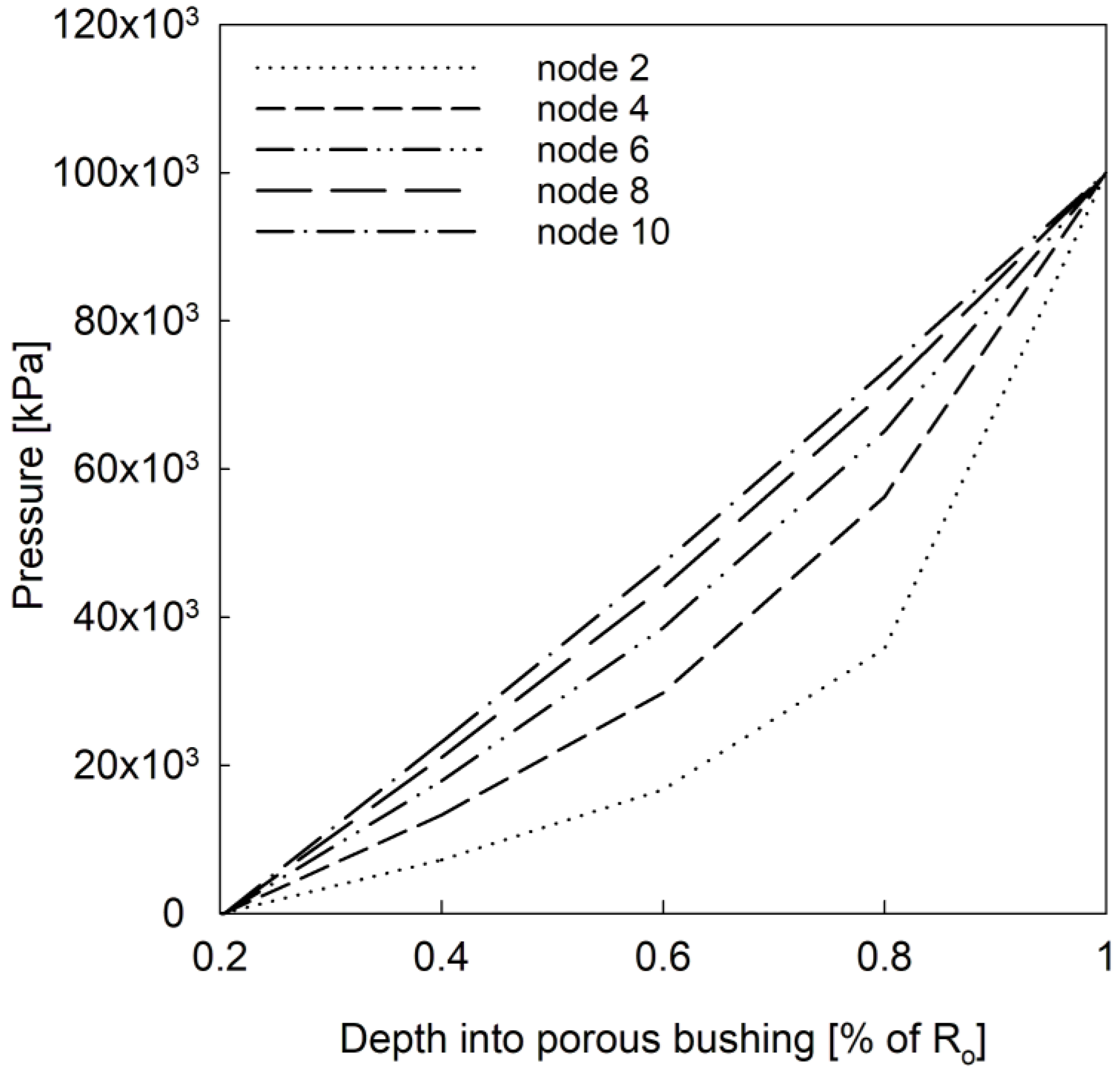
Figure 5 demonstrates the improved accuracy of a three-dimensional representation of the pressure within the bushing, compared to a simplification of assuming a linear distribution within the porous bushing. The nodes represent the axial position of the pressure distribution, with node 2 being the closest to the axial edge of the bearing and node 10 being approximately 15% towards the bearing centerline. The use of the numerical derivative improved the representation of the porous bushing for approximately 30% of the bearing’s length when both ends were accounted for.
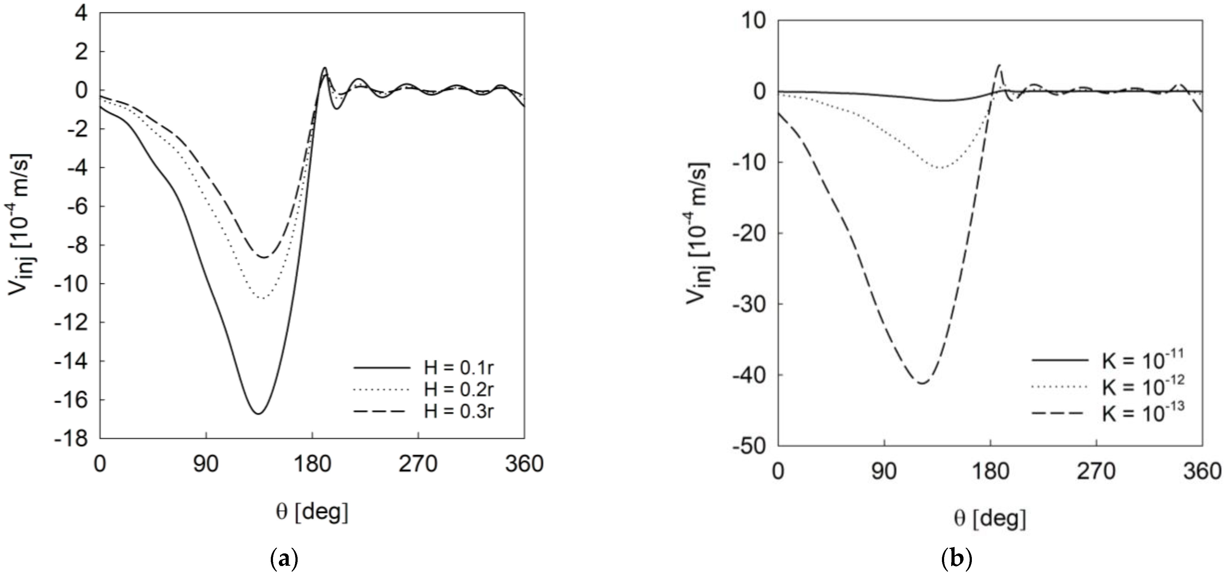
Figure 6 demonstrates the minimal effect over the range for bushing thickness. In contrast, the range of permeabilities has a significant effect on the injection velocity. This sets the stage for further discussions on the variation of these parameters and their effects on pressure distribution within the fluid film, which drives bearing load capacity and stability. The lowest permeability would not be ideal for high-load applications, as there is minimal fluid circulation (excluding side leakage), making the fluid more susceptible to cavitation and instability. The lowest permeability demonstrates the least injection velocity and thus will behave most like a solid bearing.
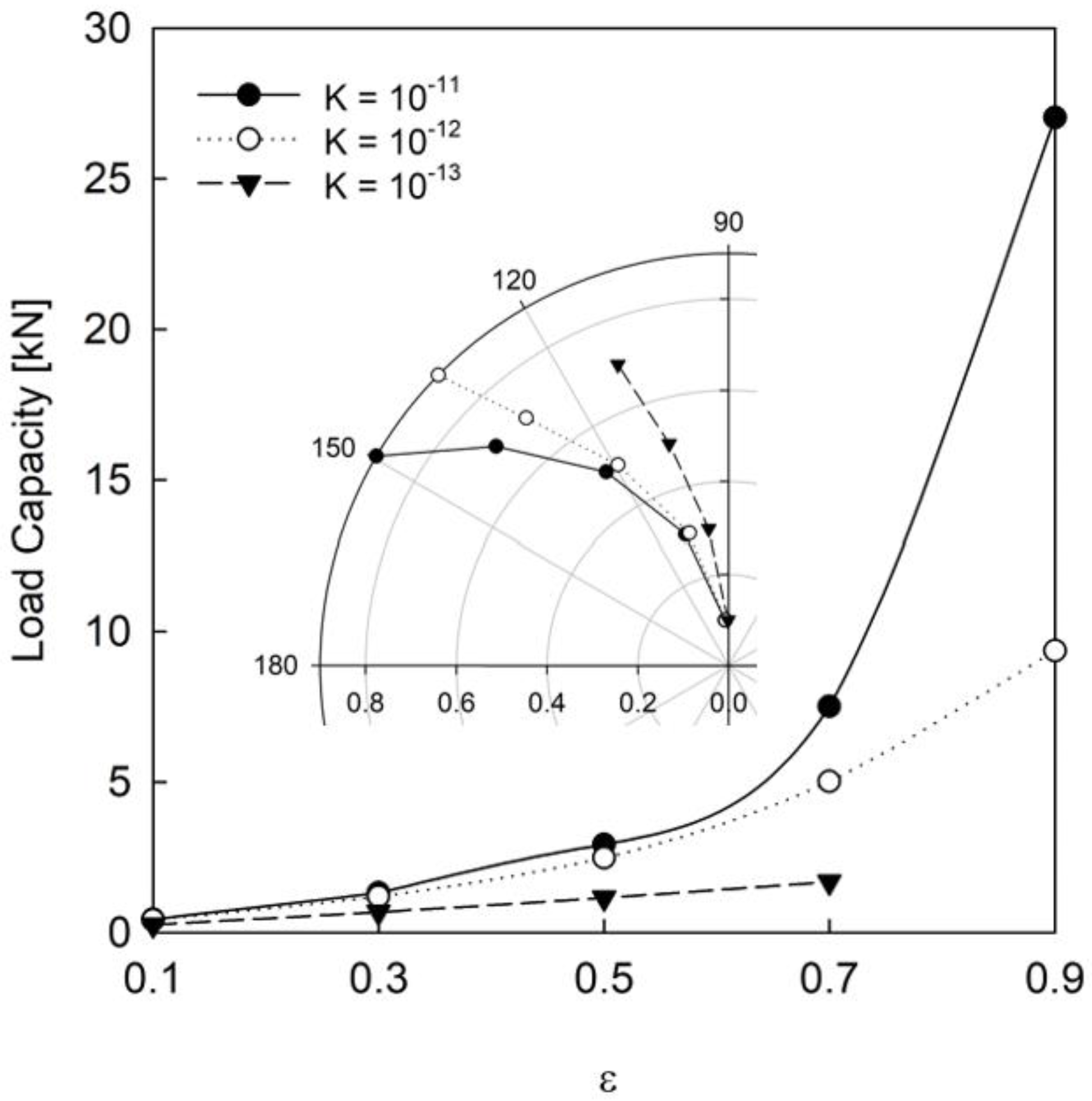
As demonstrated by
Figure 7, the effect of changing permeability on the bearing load capacity becomes significant as the bearing eccentricity increases. With the lowest permeability, which would provide the most resistance to fluid traveling through the bushing, an eccentricity ratio of 0.9 was an example of the numerical instability caused by the rapid transfer of fluid between the bearing clearance and reservoir due to the large eccentricity. With high eccentricity, the bearing and bushing have a large offset which causes a large pressure differential between the converging and diverging sections. This pressure differential is what drives the fluid motion between the bearing clearance and reservoir; when the exchange occurs at too large of a rate, then numerical convergence cannot be achieved. The relaxation factors for the pressure iteration could be employed to achieve convergence, but the simulation would no longer be time accurate.
The similar load capacity behavior of the two larger permeabilities demonstrates one of the more helpful aspects of a numerical model—finding design plateaus. Designers will know there is no significant increase in load capacity for permeability changes above
for the current bearing dimensions and environment. Readers are reminded that the injection velocity, which drives the bearing load and stability, is directly affected by the passive reservoir pressure. The pressure within this reservoir, while currently set to a constant value, would be affected in application by the initial charge of fluid into the system and the amount of side leakage. An important advancement in the modeling effort will be to realistically model the side leakage and, in practice, demonstrate the need for good seals on the axial ends of the bearing. The sub-figure demonstrates that there is also an increase in bearing stability to accompany the increase in load capacity, as the attitude angle is larger at each eccentricity. The approach towards the semi-circle shape characteristic of a solid journal bearing becomes apparent as the permeability decreases [
25,
26]. The increased load capacity for increased permeability has been demonstrated experimentally for porous journal bearings, along with a higher attitude angle [
27]. These experimental results show that, with the correct reservoir dimensions, the behavior of the self-circulating bearing mimics that of a porous journal bearing.
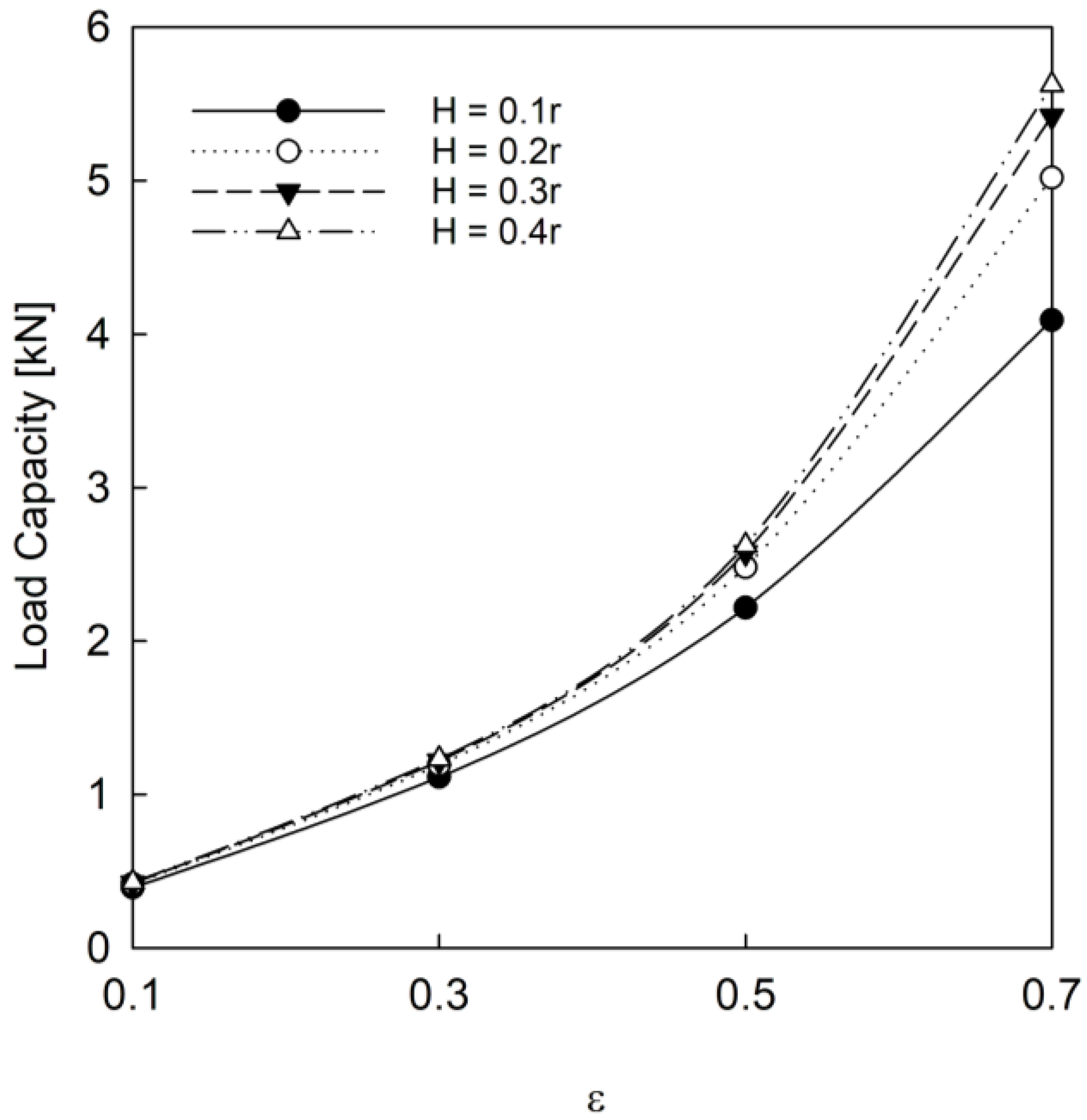
A thicker bushing is shown to promote a larger bearing load capacity in
Figure 8; this is expected from the lower injection velocity shown in
Figure 6a. The passive reservoir pressure was lower than the pressure developed in the bearing clearance, so a larger restriction on the fluid leaving the clearance provided a larger load capacity. Due to the low change in feeding parameters, the difference in load capacity, as well as the stability, was minimal. This information highlights that self-circulating bearing characteristics can be altered significantly without requiring more real estate (larger bushing radius), which is beneficial for many applications. Increasing the bushing thickness will limit the fluid leaving the bearing clearance, which increases the load capacity. This would be relevant for applications with low speed and cool temperatures that are not at severe risk for vaporous cavitation. Applications at high vaporous cavitation risk would aim to promote fluid motion to lower the overall fluid temperature.
While the results demonstrated here are valuable, the limitations of the current model require discussion. The constant property assumption may prove to be unrealistic for high-speed applications or those with large temperature differentials. The model also assumes constant supply pressure which, in application, would vary. The foundation created with this numerical model will allow for future versions to account for temperature-dependent fluid properties, multigrade fluids, and cavitation. The next proposed step in developing the model is to include gaseous cavitation to vary the fluid properties throughout bearing operation. Future applications could also include adaptations for textured porous bushings. Once the energy equation is incorporated, vaporous cavitation and heat transfer studies within the bearing will be of value for designers to recognize functioning limits based on cavitation and heat transfer.


