1. Introduction
The concept of the honeycomb sandwich structure has attracted wide attention. After decades of development, the honeycomb structure has made breakthroughs in structural design, damage resistance and material application. The unique advantages of sandwich structure are their improved energy absorption capacity and excellent impact resistance. These advantages of the sandwich structure make it widely used in engineering applications, such as the ship, automobile, aviation and aviation industries [
1]. It can be seen that the superiority of the honeycomb structure is becoming more and more prominent.
Since Junkers et al. [
2] proposed the use of a honeycomb structure in a sandwich structure in 1915, this sandwich structure has been widely used in the fuselage. At present, the common honeycomb structures are mainly circular, quadrilateral, hexagonal, corrugated, foam, negative Poisson’s ratio [
3,
4,
5,
6,
7,
8], the zero Poisson’s ratio, chiral and anti-chiral structures that have emerged in recent years [
9,
10,
11,
12]. In many cell studies, triangles, squares, circles and hexagons are the most widely used. A hexagonal honeycomb structure can obtain the maximum force with the least material. When it is subjected to out-of-plane load, its bending stiffness is almost the same as that of the same material and the same thickness plate structure, and both the structural stiffness impact resistance and energy absorption capacity are higher than other cell structures. With different combinations, there are honeycomb sandwich structures of the structural composite type, step type and mixed type of different materials [
13,
14,
15]. At present, the application in aerospace is mainly based on the hexagonal honeycomb core that imitates the honeycomb. In military protection and explosion protection, the negative Poisson’s ratio and chiral structure are widely used. The most widely used is still the explosion-proof wall. The rest of the structure is still in the research stage, and it takes a long time to be widely used.
The effectiveness of honeycomb sandwich structures is generally related to the physical properties of the structure, such as cell size, core thickness and arrangement, which affect the strength, stiffness and overall performance of the sandwich structure. The experimental results confirm that the Poisson’s ratio, elastic modulus and compressive properties of honeycombs are indeed related to topological characteristics [
16]. In recent years, the research on the design of a honeycomb core structure is in full swing, and the type of honeycomb cell has also been greatly improved on the basis of the traditional single configuration. The emergence of multi-level honeycomb provides the possibility for the structure to improve the impact resistance. Compared with the traditional honeycomb aluminum sandwich plate, the multi-level honeycomb aluminum sandwich plate has a small deflection on the back plate surface and good impact resistance under large load, and this advantage becomes more and more obvious with the gradual increase in load [
17].
Lv, X.Y. et al. [
18] found that based on the NOMEX honeycomb core, the skin is made of a multi-layer composite material, which is bonded by a high-strength adhesive film. The impact test of the structure was carried out by using the drop hammer test machine. Compared with the study of Du et al. [
19], the impact energy is relatively low, and the main energy dissipation of the structure is still dominated by the fiber tensile fracture of the composite skin. Zhang, Y.W. et al. [
20] compared the tube-reinforced honeycomb sandwich structure with the traditional honeycomb structure and found that the filling of the metal tube improved the stiffness and peak load of the traditional honeycomb structure, making the stress and deformation of the front and rear skins more uniform. The energy absorption characteristics of the structure are faster than that of the empty honeycomb structure, and the deformation of the front skin is reduced. In addition to the overall design of honeycomb structures, reports on the study of composite honeycomb structures have gradually increased. Yasui, Y. et al. [
21] conducted an experimental study on the impact and tensile properties of honeycombs with different matrix aluminum materials. It was found that the energy absorption effect of the tandem multi-layer honeycomb structure in the form of a pyramid will be relatively improved after crushing. Li et al. [
22] also carried out a numerical simulation and static compression test on the tandem aluminum honeycomb structure and obtained a buffer structure with better energy absorption characteristics.
By comparing and analyzing the difference between the protective performance of the new structure and the existing structure, based on the research status of the composite structure and the composite material, the impact resistance of the composite honeycomb structure is analyzed by the numerical simulation method, and the structural design is optimized. The impact resistance of the composite honeycomb structure is analyzed by the numerical simulation method, and the structural design is optimized, and the optimal structure is selected for the drop hammer impact test. When the honeycomb sandwich structure is subjected to the out-of-plane load, the skin stiffness and the support of the honeycomb core work together to resist the deformation and damage of the structure. The dynamic response of the structure under different impact loads is analyzed by analyzing the damage of the structure under different impact energies, the variation in the displacement, force and energy curves related to the structural resistance and time variables, and the energy absorption index per unit volume, and the damage resistance of the structure is judged. According to the displacement, force, energy and velocity curves related to time variables, the dynamic response of the composite honeycomb sandwich structure is studied, and the difference in protection performance between structures is analyzed.
2. Material and Methods
2.1. Used Materials
The composite honeycomb sandwich structure designed in this paper is a double-core composite structure. The skin material is 7075 aluminum alloy, and the core material is 2024 aluminum and 304 stainless steel. The two models of the contrast structure are composed of a core layer material of NOMEX (DuPont paper), a skin material of 7075 aluminum, and a core layer material of NOMEX and a skin material of unidirectional carbon fiber structure. The single-layer honeycomb structure and the core cell structure are shown in
Figure 1.
In order to meet the processing requirements, the diameter of the honeycomb cell used in the numerical simulation is
d = 3 mm and
d = 6.4 mm, respectively, and the cell wall thickness is 0.1 mm. W and L change with the change of cell diameter d. The structure size is given in
Table 1.
According to the UAV design method, the honeycomb cell size of the two contrast structures is selected as d = 3 mm, the core height is 15 mm, the thickness of 7075 aluminum skin is 1 mm, and the carbon fiber skin is 2 mm.
The honeycomb core material in the composite honeycomb sandwich structure is 2024 aluminum and 304 stainless steel, and the skin material is 7075 aluminum alloy. The specific parameters of the material model are shown in
Table 2.
The Lagrange algorithm is used in the composite honeycomb sandwich structure. The material models are the MAT_JOHNSON_COOK model and EOS_GRUNEISEN state equation. The flow stress of the material is expressed as the product of strain function, strain rate function and temperature function, which can reflect the influence of strain strengthening, strain rate strengthening effect and temperature softening effect of the material. The expression is [
23]
Here, σ is the plastic flow stress of the material; εp is the equivalent plastic strain; is the relative equivalent plastic strain rate; T* is the dimensionless temperature term; A is the initial yield stress at reference temperature and reference strain rate; B is the strain hardening modulus of the material; C is the strain rate sensitivity coefficient; n is the hardening index of the material; and m is the temperature softening coefficient. Tm is melting temperature; Tr is room temperature.
The * MAT_PLASTIC_KINEMATIC is selected for the two groups of structural models, and the specific parameters of the material model are shown in
Table 3.
2.2. Numerical Method
The high-speed fragment model is designed with a cylindrical structure, with a diameter of 12 mm and a height of 30 mm. The speed is set to 200 m/s. The material is 45# steel. In the simulation process, in order to eliminate the influence of fragment deformation on structural damage characteristics, the finite element model of the fragment is set as a rigid body. The finite element model of the impact structure is shown in
Figure 2.
LS-DYNA is used in the numerical simulation. In order to approximate the actual situation, the contact between the skin and the core is a fixed connection failure method. The contact surface between the skin and the core is firmly connected, allowing the two surfaces to slide and separate from each other after failure. The deformation of the honeycomb core is a complex process. In addition to the contact between the skin and the core, the honeycomb cells themselves also interact. Therefore, the honeycomb core is automatically set to face-to-face contact. The composite honeycomb structure adopts an eight-node hexahedral solid element. Since the composite model is symmetrical, in order to reduce the number of calculation units, a quarter model is established for calculation. In order to prevent the displacement of the edge of the composite honeycomb structure, the degree of freedom of the solid elements at the edge in the X, Y, and Z directions is limited. The rest of the solid elements have six degrees of freedom for the displacement and rotation of X, Y and Z. Therefore, in order to approximate the actual situation, the contact between the skin and the core is a fixed connection failure method. The contact surface between the skin and the core is firmly connected, allowing the two surfaces to slide and separate from each other after failure.
In order to analyze the influence of cell size, material and composite method on the anti-damage performance of the composite honeycomb sandwich structure, a total of 18 groups of structures were designed for numerical simulation of high-speed fragment impact. According to the simulation results, several groups of composite honeycomb sandwich structures with the best protective performance were selected for experimental research. See
Table 4 for details.
Among them, Al/Al indicates that the material of the upper and lower honeycomb cores is 2024 aluminum; Al/St indicates that the upper core material is 2024 aluminum, and the lower core material is stainless steel; St/St indicates that the material of the upper and lower honeycomb cores is stainless steel; and St/Al indicates that the upper core material is stainless steel, and the lower core material is 2024 aluminum. NOMEX indicates that the core material is NOMEX; d3 indicates that the core cell diameter is 3 mm; and d6.4 indicates that the core cell diameter is 6.4 mm.
2.3. Numerical Simulation Results
Taking the fragment penetrating 1# structure as an example, the simulation process is shown in
Figure 3. At 50 μs, the first layer of the skin begins to sag and deform, and the upper core layer is deleted because the material deformation exceeds the set failure maximum value, and some core layer materials are exposed around the sag. At 100 μs, the fragment penetrates the second layer of skin, and the lower core layer begins to fail and delete, and the middle and bottom skins deform seriously in the direction of fragment impact, the connection between the plugging block and the structure is reduced, and the gap is clearly visible. At 150 μs, the fragment penetrated the underlying skin.
Considering the influence of materials on the energy absorption characteristics of the structure under the same structural size, this paper divides the 1# and 9#, 2# and 10#, 3# and 11#, and 4# and 12# structures into 4 groups and compares and analyzes the energy absorption effect.
Figure 4 is the comparison of skin energy absorption effect.
Figure 4 shows the comparison of skin energy absorption per unit time of 8 groups of structures with the same composition. The amount of skin bearing capacity depends on the support degree and the maximum deformation degree of the core layer during the deformation process. Due to the inertia effect of the core layer of the honeycomb sandwich structure, the energy absorption effect of the first layer skin is not much different. At the same time, due to the different support degrees of the core layer, the energy absorption of the middle skin changes, and the two curves are obviously separated. The plastic deformation space of the structural skin with a low support degree increases, and the energy absorption is relatively improved. The structure with high support is obviously subjected to shear action, and the crushing time and density will increase accordingly, which will apply a large amount of load to the bottom skin in advance and deform, resulting in a relatively low level of the energy absorption curve in the later stage.
From
Table 5, it can be found that the energy absorption per unit volume of the structure with the core material of 304 stainless steel is higher than that of the structure with the core material of 2024 aluminum, and the same type of structure is 24.7%, 13.2%, 17.6% and 11.3% higher, respectively. It can be seen that the energy absorption characteristics of the composite honeycomb sandwich structure have a great relationship with the material composition of the structure. The opening diameter of the composite honeycomb sandwich structure with the upper and lower cores of 304 stainless steel is smaller than that of the structure with the upper and lower cores of 2024 aluminum, and the maximum openings are 2.6%, 4.5%, 1.3% and 0%, respectively. The strength of the core layer of the structure will limit the plastic deformation range of the skin to a certain extent, resulting in a larger shear effect on the structural skin and a smaller pore size.
Figure 5 is the comparison of core energy absorption effect.
Figure 5 is the comparison of the energy absorption per unit time of the core layer of 8 groups of structures with the same composition. Different from the energy absorption characteristics of the skin, the energy absorption characteristics of the core layer are divided into two parts. One part is the energy load indirectly applied to the core layer during the impact deformation of the skin, and the other part is the energy absorbed by the deformation, shear, tensile failure and accumulation compaction caused by the direct contact of the fragment with the core layer after the skin is damaged. The energy absorption characteristics of the core layer are closely related to the strength of the material. After the fragments contact the first layer of the skin, the energy absorption curve of the core layer always maintains an upward trend due to the pressure of the skin. After the skin is broken, the plastic deformation in the deformation mode of the core layer is relatively reduced, and the shear stress increases. After the maximum point appears at 25 μs, the curve begins to decline. At this time, the part of the upper core layer reaching the ultimate stress value accounts for about 1/4 of the overall core layer. At 50 μs, the curve has a minimum point. At this time, the material of the upper core layer in the coverage area of the impact direction of the fragment is all damaged and deleted. The second layer of the skin continues to exert pressure on the lower core layer. Since the structure is set to be simply supported and fixed at the edge, after the upper core layer reaches the ultimate stress value, the deformation space of the remaining honeycomb core layer below the structure is relatively increased due to the lack of support below the structure. This leads to the extension of the deformation and energy absorption time of the skin and the core layer, and the curve always maintains an upward trend.
Through the comparison of four sets of curves, it can be found that the energy absorption effect of the core layer of the composite honeycomb sandwich structure with 304 stainless steel as the honeycomb core is higher than that of the structure with the core layer of 2024 aluminum in the case of small cell density, and the smaller the cell density under the same structure, the greater the curve difference.
Figure 6 is the Total energy absorption curves of 8 structures.
Figure 6 shows the curve of the total energy absorption of 8 groups of structures with time. From
Figure 6a, it can be seen that the difference in the total energy absorption per unit of several groups of structures is not significant. Because the above eight groups of curves are repeatedly staggered in the size and position of each period, it cannot effectively distinguish the total energy absorption of each group of structures. Therefore, the curve is integrated to judge the energy absorption of the structure. The overall energy absorption effect of the structure is found by integration. The maximum integral area of the 9# structure is 7589.1, and the minimum integral area is 5680.2 of the 12# structure, with a difference of 33.6%. The 8 groups of structures with a better energy absorption effect are all concentrated on the structure with the upper core layer of 304 stainless steel. It can be seen that the material strength of the core layer has a great influence on the overall energy absorption effect. The higher the material strength, the stronger the overall energy absorption effect of the structure.
3. Experimental Results and Discussion
3.1. Drop Hammer Test
Based on the results of numerical simulation, four groups of 304 stainless steel honeycomb cores with the best protective performance were selected from 16 groups of structures with 2024 aluminum and 304 stainless steel as honeycomb cores for drop hammer impact experiments and compared with 7075 aluminum and NOMEX honeycomb core composites and unidirectional carbon fiber and NOMEX honeycomb core composites.
Figure 7 is the honeycomb core layer pattern.
The core layer was cut into the expected experimental size of 150 mm × 150 mm, and the core layer was bonded to the skin by K-7007 room temperature curing special strong adhesive. The bonded honeycomb sandwich structure was placed at a ventilated place, and a 50 kg load was applied to the upper surface of the specimen for 20 days to achieve the purpose of firm bonding.
There are six types of composite honeycomb sandwich structures in the drop hammer impact experiment, which are the diameter of the double-layer honeycomb cell is 3 mm, the diameter of the upper honeycomb cell is 3 mm, the diameter of the lower honeycomb cell is 6.4 mm, the diameter of the upper honeycomb cell is 6.4 mm, the diameter of the lower honeycomb cell is 3 mm, the diameter of the double-layer honeycomb cell is 6.4 mm, and Al/NOMEX and C/NOMEX. The size of the specimens is 150 mm × 150 mm. The diameter of the NOMEX honeycomb cell is 3 mm, and the thickness of the core layer is 15 mm. The thickness of single layer core of 304 stainless steel honeycomb is 8 mm; 7075 aluminum skin thickness of 1 mm; and the thickness of the unidirectional carbon fiber skin is 2 mm.
Figure 8 is the six types of composite honeycomb sandwich structures.
Where D = 3 mm represents the cell diameter of the honeycomb core is 3 mm, D = 6.4 mm represents the cell diameter of the honeycomb core is 6.4 mm, TOP represents the upper layer, and the bottom represents the lower layer. AL/NOMEX represents the core NOMEX material, skin 7075 aluminum, C/NOMEX represents that the core material is NOMEX, and the skin material is unidirectional carbon fiber.
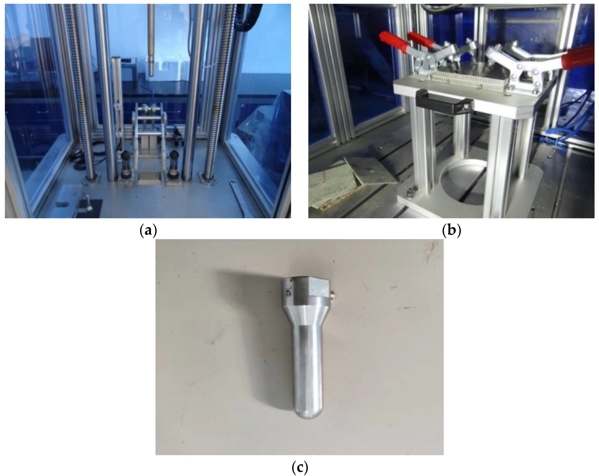
The STLH-150 drop weight test machine, produced by Shangtai Experimental Instrument Co., Ltd. (Jinan, China), was used to carry out impact experiments on the samples. The maximum impact energy of the experimental machine is 150 J, the diameter of the impact head is 20 mm, the reserved size of the punch is 75 mm × 125 mm, and the remaining height space of the impact is 300 mm. The specimen is fixed by the base of the impact support fixture and the fixed clamp with a rubber head. The feedback data of the drop test machine are collected by the instrumented drop control system, and the process of the drop penetrating the composite honeycomb sandwich structure is collected by using the high-speed photography equipment. The experimental device is shown in
Figure 9.
3.2. Experimental Results
The drop impact test piece is a process of impact and rebound. The impact experiments of the same type of composite honeycomb sandwich structure are carried out with 100 J and 150 J energy, respectively, and the data are collected by the data acquisition system. The drop hammer experiment scheme is shown in
Table 6.
Among them, 3 indicates that the diameter of the honeycomb core cell is 3 mm, 6.4 indicates that the diameter of the honeycomb core cell is 6.4 mm, AL/NOMEX indicates the core NOMEX material, the skin 7075 aluminum, C/NOMEX indicates that the core material is NOMEX, and the skin material is unidirectional carbon fiber, Top indicates the upper core layer of the composite honeycomb sandwich structure, and Bottom indicates the lower core layer of the composite honeycomb sandwich structure.
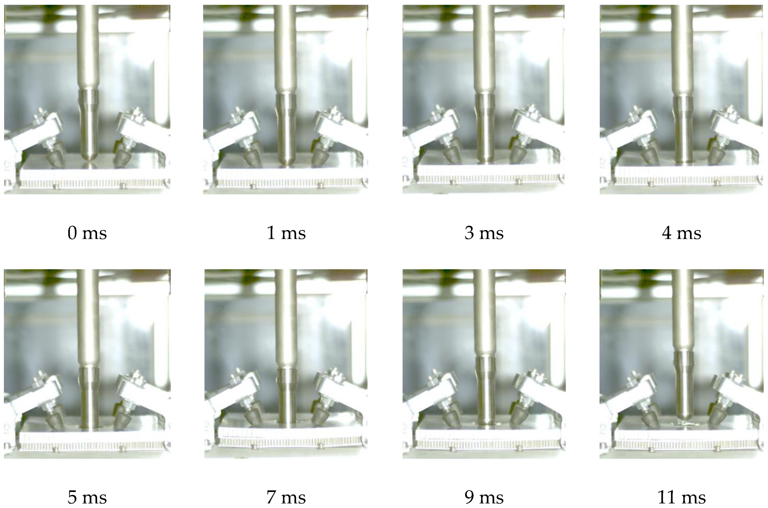
Taking 150 J energy impact Top3-Bottom3 as an example, the process of the drop hammer penetrating the specimen is shown in
Figure 10.
For the specimen of Top3-Bottom3, the penetrator contacts with the specimen at 1 ms, and there is a slight depression on the upper surface. At 3 ms, the penetrator penetrates the upper surface and crushes the honeycomb core layer at 4 ms. At 7 ms, the impact limit is reached, and the transient deflection at the center of the specimen reaches the maximum. At 9 ms, the penetrator begins to rebound, and the deformation of the specimen gradually recovers. The impact effects of different impact energies on the composite honeycomb sandwich structure are shown in
Table 7 and
Table 8.
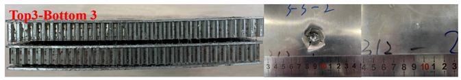
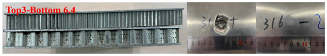
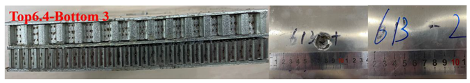
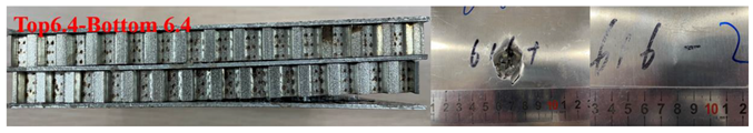
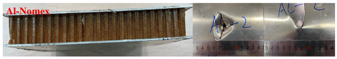
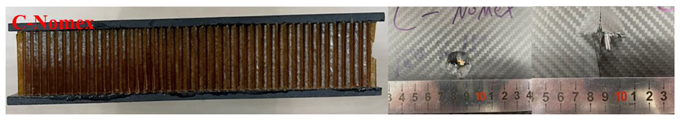
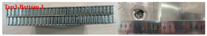
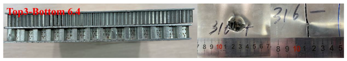
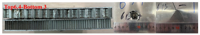
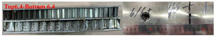
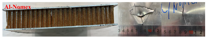
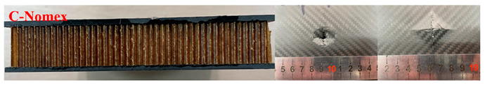
Under the impact of 100 J energy, C-NOMEX is completely broken, Al-NOMEX bottom skin is broken, and the crack propagation is close to the edge position. The other structures are damaged to varying degrees, among which the deformation of the bottom skin of the Top3-Bottom3 structure is not obvious, the deformation of the bottom skin of the Top3-Bottom6.4 and Top6.4-Bottom3 structures is similar, and the deformation of the bottom skin of the Top6.4-Bottom6.4 structure is serious.
With the increase in impact energy, the protrusions of the underlying skin of the Top3-Bottom3 structure increase, but no cracks are generated. The underlying skin of the structure with a cell size of 6.4 mm in the lower core layer is completely broken. The Top6.4-Bottom3 structure has a petal-shaped damage trend, but the petal center is not fully opened. The bottom skin of the Al-NOMEX structure completely breaks with the increase in impact energy. There is no significant difference in the damage effect of C-NOMEX under the impact energy of 150 J. After the carbon fiber skin is broken down, the fiber filaments gather at the punching hole, resulting in the complete occlusion of the damaged aperture.
3.3. Analysis of Energy Absorption Characteristics of Composite Honeycomb Sandwich Structure
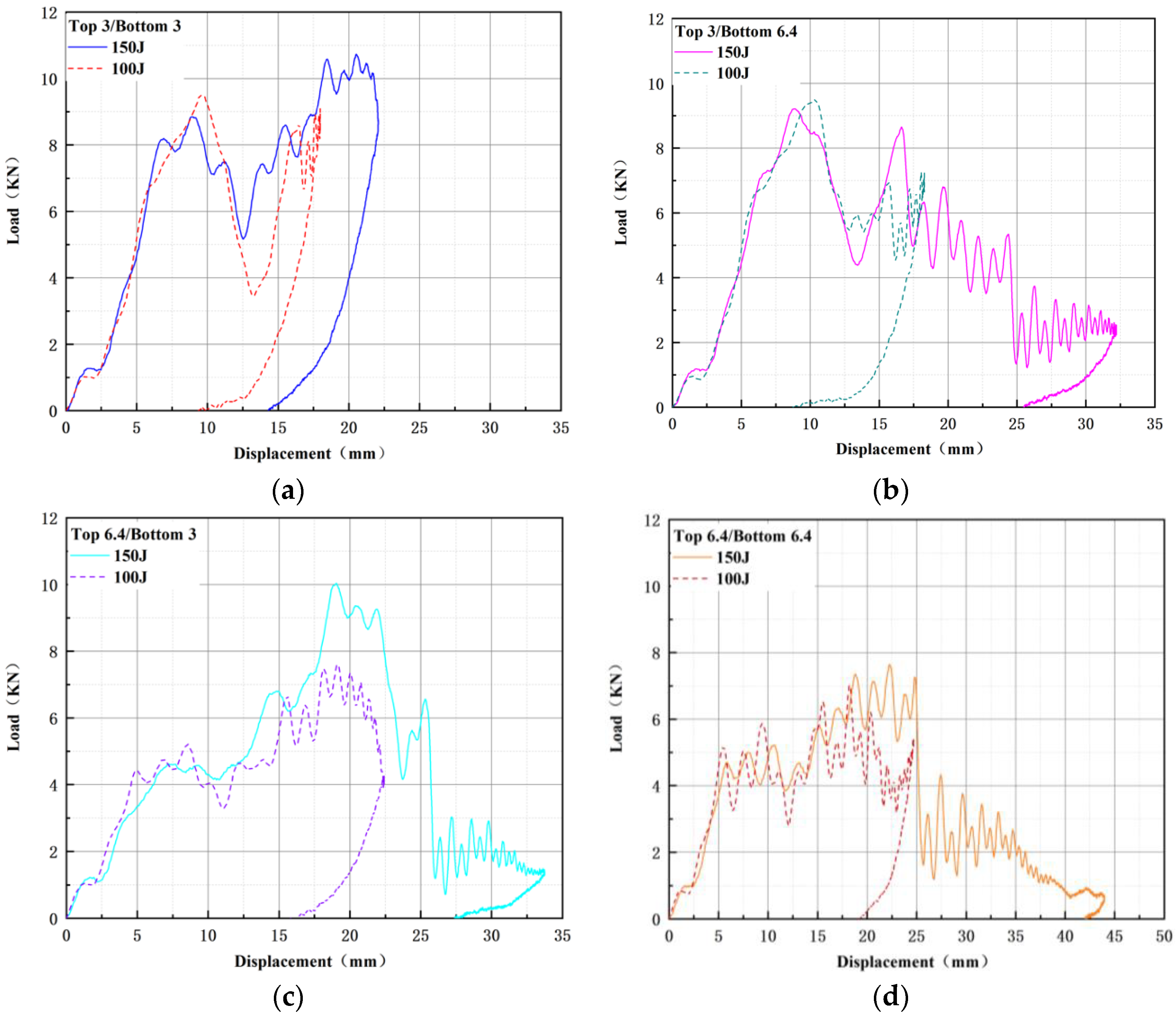
The energy absorption index is one of the main factors considered in structural design. In the process of drop impact, the gravitational potential energy of the drop is converted into kinetic energy to penetrate and compress the structure, but the kinetic energy is quadratic, and the force analysis process is more complicated. Therefore, the energy absorption characteristics of the structure are analyzed by returning to the gravitational potential energy itself. Since the potential energy U has a linear relationship with the experimental force F, and the potential energy U also has a linear relationship with the displacement S, the bilinear function is used to represent the energy absorption characteristics of the experimental specimen, that is, U = FS [
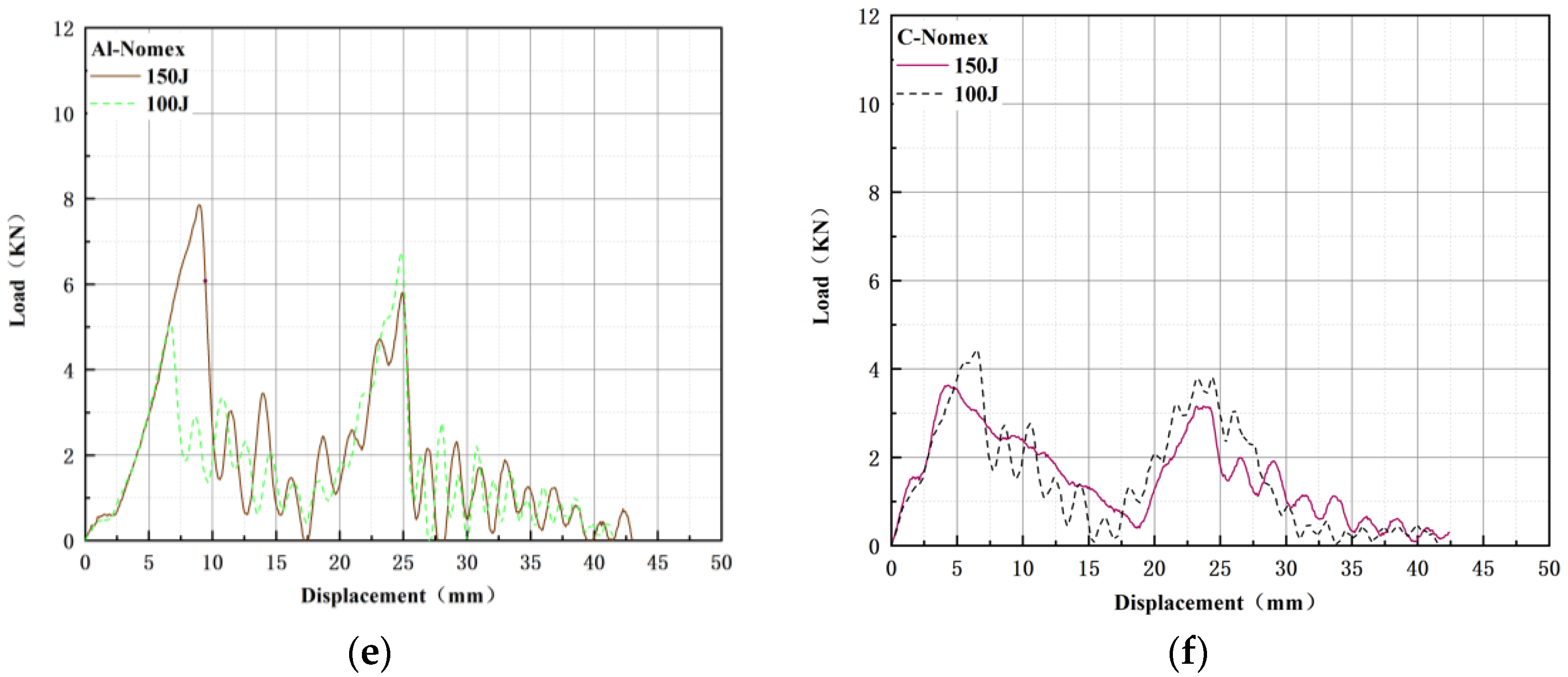
24]. The force–time and displacement–time curves obtained by the impact of the specimen were integrated by using the acquisition system of the drop test machine, and the force–displacement curves under different impact energies were obtained to judge the energy absorption characteristics of the structure. The force–displacement curves of the six structures under different impact energies are shown in
Figure 11.
The total energy (
TEA) absorbed by the composite honeycomb sandwich structure during impact is caused by impact. The total energy value is the area enclosed by force-displacement, and the expression is [
25]
The total energy absorption of the honeycomb sandwich structure is obtained by summing the integral area of the curve. The total energy absorption of the 12 groups of structures is shown in
Table 9.
Through
Table 7,
Table 8 and
Table 9, it can be found that with the increase in the damage degree of the composite honeycomb sandwich structure, the total absorption energy of the structure gradually increases. Because Al-NOMEX and C-NOMEX are completely penetrated under different impact energies, the energy absorption limit of the structure is about 80 J and 64 J.
However, through the instantaneous damage compression and energy absorption characteristics, it can be seen that for the buffer structure, the composite honeycomb sandwich structure with the upper and lower core cell diameters of 6.4 mm has a good energy absorption effect in high-speed buffering, and the structure collapses quickly, which has a good reference for the design of one-time buffer structure. The structure with the cell diameter of the upper and lower core layers of 3 mm has the smallest impact displacement of the drop hammer under the same energy impact, the deformation of the underlying skin is not obvious, and the crashworthiness advantage is obvious, which has a good reference for the design of the anti-collision structure.
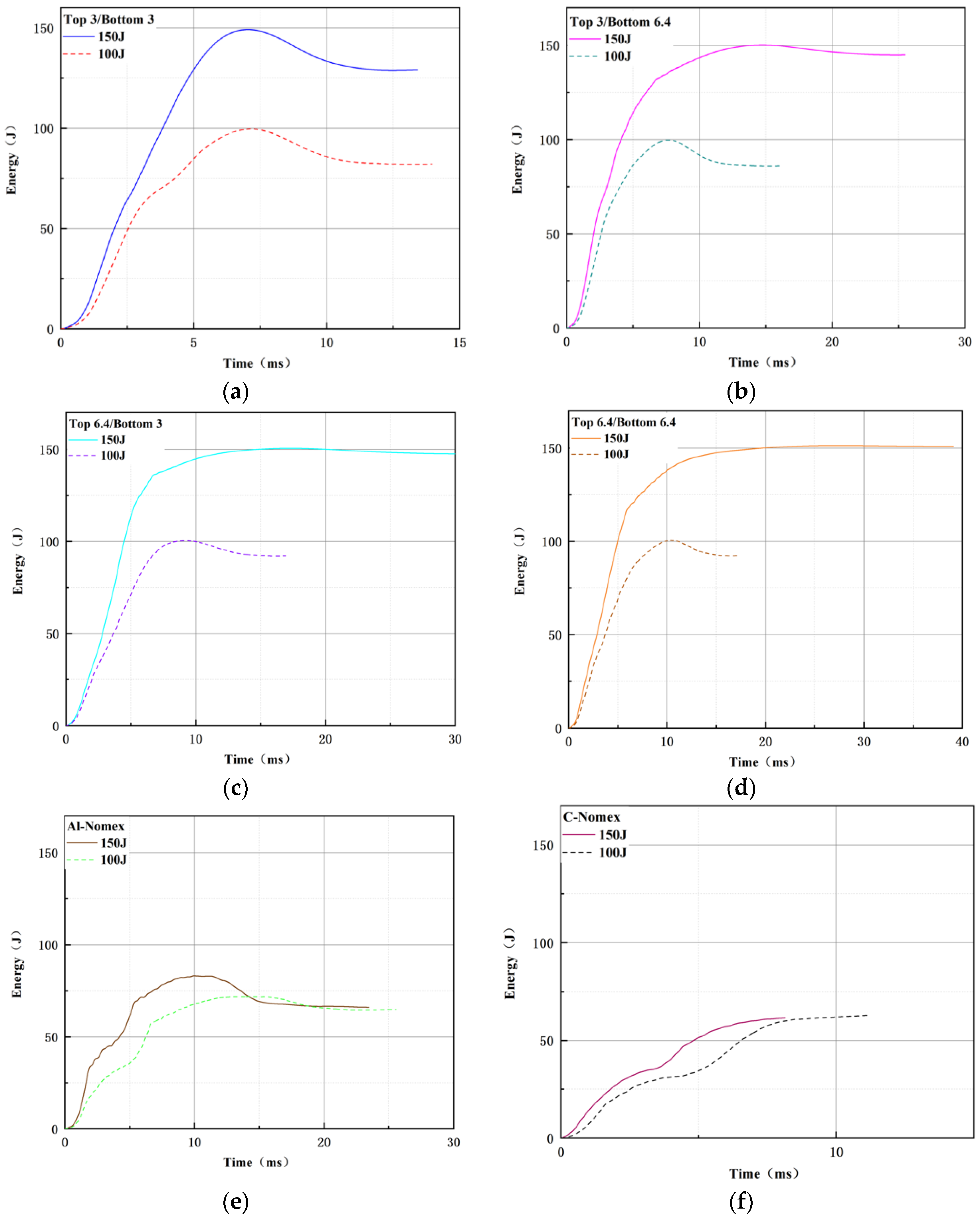
Due to the different structural configurations, the equal displacement method cannot be used to judge the overall energy absorption characteristics of the structure. In order to more intuitively observe the energy change when the drop hammer penetrates the structure, the energy–time curve is drawn according to the feedback information, as shown in
Figure 12.
Through the energy–time curve, it can be seen that the limit energy of the drop is transferred to the specimen, and the time to reach the maximum value is different. The shorter the time to reach the maximum value, the stronger the resistance characteristics of the structure, and the stronger the cushioning performance of the structure. In the process of impact, the transient energy of the two groups of curves
Figure 12e,f did not reach the maximum value. It can be seen that the advantages of Al-NOMEX and C-NOMEX structures in both anti-impact performance and energy absorption characteristics are not obvious.
Whether at 100 J or 150 J impact energy, by comparing the first four sets of curves
Figure 12a–d, it can be found that the maximum value of some curves exceeds the limit energy setting. According to the order of impact, with the increase in impact times, the trend of the curve exceeding the maximum limit value is more obvious, but the numerical fluctuation is not large. Through research, it is found that the reason for the impact energy exceeding the maximum value is that a small amount of special strong adhesive is bonded to the impact head in the first impact composite structure, resulting in the falling energy exceeding the set maximum energy value. Therefore, there are certain errors in the other curves after the Top3-Bottom3 curve, and the error value is the micro-error value above 150 J.


