Article

Dynamic Modeling and Altitude Control for Flying Cars Based on Active Disturbance Rejection Control

1
School of Mechanical and Electrical Engineering, Central South University, Changsha 410083, China
2
College of Artificial Intelligence, Nankai University, Tianjin 300350, China
*
Authors to whom correspondence should be addressed.
Appl. Sci. 2024, 14(7), 2754; https://doi.org/10.3390/app14072754
Submission received: 21 February 2024 / Revised: 16 March 2024 / Accepted: 20 March 2024 / Published: 25 March 2024
(This article belongs to the Special Issue Research and Development of Intelligent Robot)

Abstract

:
Flying cars offer huge advantages due to their deformable structure, which can adapt to external environments and mission requirements. They represent a novel system that can realize vertical takeoff and landing. However, the structure of a flying car is complicated, placing higher requirements on modeling accuracy and control effectiveness. Thus, in this paper, a dynamic model of a flying car is proposed by combining a car body, motor, and propellers. Then, a double-loop controller based on active disturbance rejection control is proposed to accurately control its flight altitude. Utilizing the extended state observer, external wind and other disturbances are regarded as an extended state, which can be dynamically observed and compensated to significantly improve tracking accuracy. The effectiveness of the proposed controller is validated through detailed simulations and flight experiments. The proposed controller significantly improves control accuracy and disturbance rejection capability.

1. Introduction

Due to their strong adaptability and ability to perform various tasks, flying cars have not only become a new choice for future urban transportation but also play an essential role in sustainable mobility [1] and transportation systems [2]. However, the control strategy of the flying car is more complicated due to its propulsion system [3,4], placing higher requirements on its control effectiveness and modeling accuracy.
Recently, electric power has become the key development direction for flying car propulsion [5,6,7]. Electrically powered flying cars still face many issues that urgently need to be solved. For example, Ref. [8] explored the wireless communication problem of the flying car. Ref. [9] proposed an efficient intelligent energy management strategy for a hybrid-powered flying car, using reinforcement learning methods to enhance the endurance of the hybrid flying vehicle. Compared to the aforementioned issues, the control problem of flying cars is more crucial and has gained widespread attention from scholars, both domestically and internationally. In the modeling of flying cars, Ref. [10] proposed a method for the rapid design and evaluation of the aerodynamic performance of the Ducted Fan Lift System (DFLS) for vertical takeoff and landing of flying cars. Ref. [11] designed an autobody model of flying cars and explored their aerodynamic characteristics. Ref. [12] tested the aerodynamic characteristics of flying cars, using different states in the simulation such as ground travel, vertical takeoff, and landing. Ref. [13] also tested the aerodynamic characteristics of flying cars with a special bionic seagull wing. Ref. [14] built a model of a flying car that incorporated a ground driving module and an aerial flight module. Meanwhile, considering that many flying cars are powered by electricity [15,16], the modeling of the propellers is also very important. In principle, the propeller model of flying cars is similar to that of UAVs [17,18,19]. Considering the fluid–rigid body interaction, Ref. [20] built a dynamic model of a flying car with four contra-rotating propeller units. A moving computational domain method was also designed to track the reference trajectory.
Besides the modeling method, the control and simulation problem of flying cars is also an important issue. Ref. [21] optimized the airframe of flying cars for medical emergencies. Ref. [22] proposed the concept of rectangular-shaped unmanned surveillance flying cars and designed an adaptive fuzzy algorithm. Ref. [23] tested the takeoff and landing performance of flying cars in a wind tunnel. Ref. [24] proposed a nonlinear controller for both the position and attitude of flying cars. A strategy was also presented to avoid saturation of the distributed propulsion control inputs. Ref. [25] built a 6-DOF model by considering the interaction between the fluid and rigid body and conducted a numerical simulation of the flying car in a sudden rotor-stop scenario. Ref. [26] designed a hierarchical control strategy for flying cars with two models: one for ground operation and one for aerial operation. The proposed method can realize accurate tracking control and improve fuel economy. Ref. [27] explored a method for a new VTOL-propelled wing design for flying cars. Ref. [28] proposed a marker-based 3D position-prediction algorithm to predict the trajectory of flying cars in two modes. Ref. [29] designed a novel flight control system for flying cars based on Bernoulli’s principle.
Based on the above discussion, it can be seen that current research tends to focus more on the ‘flight’ aspect of flying cars, especially in the vertical takeoff and landing stages. However, the aerodynamic characteristics of flying cars are more complicated. There is also relatively less consideration for disturbances, with most studies limited to investigating their nonlinear characteristics and designing nonlinear controllers, leading to insufficient disturbance resistance. For this reason, in this paper, we focus on the altitude control of the flying car during the flight portion. Firstly, the model of the flying car is proposed. The model consists of an unmanned vehicle body, motor, and propellers, enabling accurate simulation of the dynamic characteristics of a flying car. It provides a viable testing platform for controller design and controller parameter tuning. Meanwhile, a double-loop controller based on active disturbance rejection control (ADRC) is designed to accurately control its flight altitude. The double-loop controller is applied to control the rotation speed of the motor and the flight altitude. ADRC was originally designed by Jingqing Han [30]. Refs. [31,32,33,34,35] also explored nonlinear ADRC and presented stability proofs. Since nonlinear ADRC is sometimes too complicated for actual applications, Ref. [36] presented linear ADRC. In ADRC, the total disturbance and internal uncertainty can be regarded as an extended state by using an extended state observer (ESO). This extended state can be dynamically observed and compensated for. Furthermore, in this paper, the proposed controller is verified through detailed simulations and flight experiments. The average tracking error of the flight altitude is less than 1 m.
This paper is divided into the following sections. Section 2 presents the dynamic model of the flying car, including the body part, motor, and propellers. Section 3 presents the control strategy. The detailed simulations and experiments are presented in Section 4 and Section 5.

2. Dynamic Model

The flying car in this paper is driven by electric energy. Thus, the flying car is equipped with four sets of propellers. In this paper, as shown in Figure 1, the structure of the proposed flying car is similar to the structure of a quadrotor UAV. Thus, its structure is also similar to that of a quadrotor UAV [37,38,39]. In the controller design for quadrotor UAVs, disturbances are mainly regarded as unknown states [40,41] that are observed by an observer. In this paper, the dynamic model of the flying car consists of three parts: the vehicle body, motor, and propellers. The flying car is powered by electric energy. Thus, the propeller rotation speed is controlled by the motor. The thrust of the propellers is then sent to the body model, which controls the flight altitude. By modeling these three parts, the main disturbances can be incorporated into the model, offering huge advantages for controller design.

2.1. Structure of Flying Car

The forces on the flying car can be expressed as illustrated in Figure 2. Besides the gravity, the lift forces are produced by the propellers. In the force analysis of the flying car, E O E , e x , e y , e z denotes the geodetic coordinate system and B O B , b x , b y , b z denotes the body coordinate system. The relationship between these two systems can be expressed as:
x y z = R X Y Z = C θ C ψ S θ S ϕ C ψ S ψ C ϕ S ψ S ϕ + S θ C ϕ C ψ S C θ C ϕ C ψ + S θ S ϕ S ψ S θ S ψ C ϕ S ϕ C ψ S θ S ϕ C θ C θ C ϕ X Y Z
where C x = c o s ( x ) , S x = s i n ( x ) , [ X , Y , Z ] denotes the position in the body system, P = [ x , y , z ] denotes the position in the geodetic coordinate system, and R denotes the transfer matrix.
Define ω B = p , q , r T . It is represented as:
ω B = 1 0 S θ 0 C ϕ C θ S ϕ 0 S ϕ C θ C ϕ ω E
where ω E = θ , ϕ , ψ T denotes the Euler angle in the geodetic coordinate system.
Based on Figure 2, the lift forces of the propellers can be expressed as:
F = 0 0 i = 1 4 l F i T T
where l denotes the distance between the propeller and its body and F i T denotes the lift forces of the four propellers.
Based on the above equations, the translational motion of the flying car can be expressed as:
m P ¨ = R F = 0 0 m g + d F
P ¨ = R F m 0 0 g + d F m
where m denotes the mass of the flying car, g denotes the gravity, F denotes the force on the flying car, and d F = [ d 1 , d 2 , d 3 ] T denotes the external disturbance on the moment of the flying car.
The moment of the forces can be expressed as:
m F = l F 4 F 2 l F 3 F 1
m A = ϖ Ω 2 2 + Ω 4 2 Ω 3 2 Ω 1 2
m d = d ϕ p ˙ d θ q ˙ d ψ r ˙ T
where Ω i denotes the rotation speed of the motor, ϖ denotes the reaction torque coefficient, d ϕ , d θ d ψ represents the aerodynamic drag coefficient, m F denotes the moment of the lift force, m A denotes the reaction torque of the propellers, and m d denotes the moment of the air resistance.
Meanwhile, based on the theorem of the moment of momentum, the rotation of the flying car can be expressed as:
m B = I B ω ˙ B + ω B × I B ω B + m d
ω ˙ B = I B 1 m B m d ω B × I B ω B
p ˙ q ˙ r ˙ = I y I z I x q ˙ r ˙ d ϕ I x p ˙ + m B x I x I z I x I y p ˙ r ˙ d θ I y q ˙ + m B y I y I x I y I z q ˙ p ˙ d ψ I z r ˙ + m B z I z
where m B = m F m A T = m B x m B y m B z T , I b = I x 0 0 0 I y 0 0 0 I z .
Then, the control inputs of the flying car are determined by the lift forces generated by the propellers and are denoted as U i F = , i = 1 , 2 , 3 , 4 . These inputs are represented as:
U 1 F U 2 F U 3 F U 4 F = l F 1 + F 2 + F 3 + F 4 l I x F 2 F 4 l I y F 1 F 3 ϖ I z Ω 1 2 Ω 2 2 + Ω 3 2 Ω 4 2
By combining the above equations, the translational motion of the flying car can be expressed as:
x ¨ = C ϕ S θ C ψ + S ϕ S ψ U 1 F + d 1 m y ¨ = C ϕ S θ S ψ S ϕ C ψ U 1 F + d 2 m z ¨ = C ϕ C θ U 1 F + d 3 m
Furthermore, with Equation (12), it yields:
m B = m F m A = m B x m B y m B z = l F 4 F 2 l F 3 F 1 ϖ F 2 + F 4 F 1 F 3 = U 2 I x U 3 I y U 4 I z
Combining Equations (11) and (14), the rotation of the flying car can be rewritten as:
p ˙ q ˙ r ˙ = I y I z I x q ˙ r ˙ d ϕ I x p ˙ + U 2 + d 4 I z I x I y p ˙ r ˙ d θ I y q ˙ + U 3 + d 5 I x I y I z q ˙ p ˙ d ψ I z r ˙ + U 4 + d 6
where d 4 , d 5 , d 6 denote disturbances on the rotation moment of the flying car.
By combining the above equations, the dynamic model of the system can be obtained. However, it is obvious that the lift forces and the rotation speed of the propellers are all important in the model. These variables are the control input of the system. Thus, in this paper, the model of the motor and the propeller are embedded into the model.

2.2. Motor Model

In this paper, the flying car is electrically driven. Thus, a brushless DC motor is applied. Firstly, the armature voltage and the exciting voltage of the motor can be expressed as:
U a = E + I a R a + L a d I a d t
U f = I f R f + L f d I f d t
where the subscript a denotes the variables of the armature voltage, the subscript f denotes the variables of the exciting voltage, E denotes the induced electromotive force, and R, I, and U denote the resistance, electricity, and voltage, respectively.
From Equation (16), we have:
E = C e Φ n = C e Φ 30 ω m π
where C e denotes the electromotive force coefficient, Φ denotes the magnetic flux, and n and ω m denote the rotation speed of the motor in r/min and rad/s.
The electromagnetic torque of the motor T e can be given as:
T e = 30 π C e Φ I a
Based on the above equations, the motion equation of the motor can be expressed as:
d d t I a I f n = R a L a 0 C e Φ L a 0 R f L f 0 C e Φ J 0 0 I a I f n + 1 L a 0 0 0 1 L f 0 0 0 1 J U a U f T L
Using Equation (20), the rotation speed of the motor can be obtained, which is applied to accurately calculate the thrust of the propellers.

2.3. Propeller Model

Finally, using the rotation speed, the thrust of the propellers can be obtained as:
F t h = ρ C D 4 n 2 = C t h n 2
where ρ denotes the air density, C denotes the propeller coefficient, D denotes the diameter of the propeller, and C t h denotes the coefficient of the thrust.
The dynamic model of the flying car can be built based on the above statements. In the next section, the ADRC controller is designed to control its flight altitude.

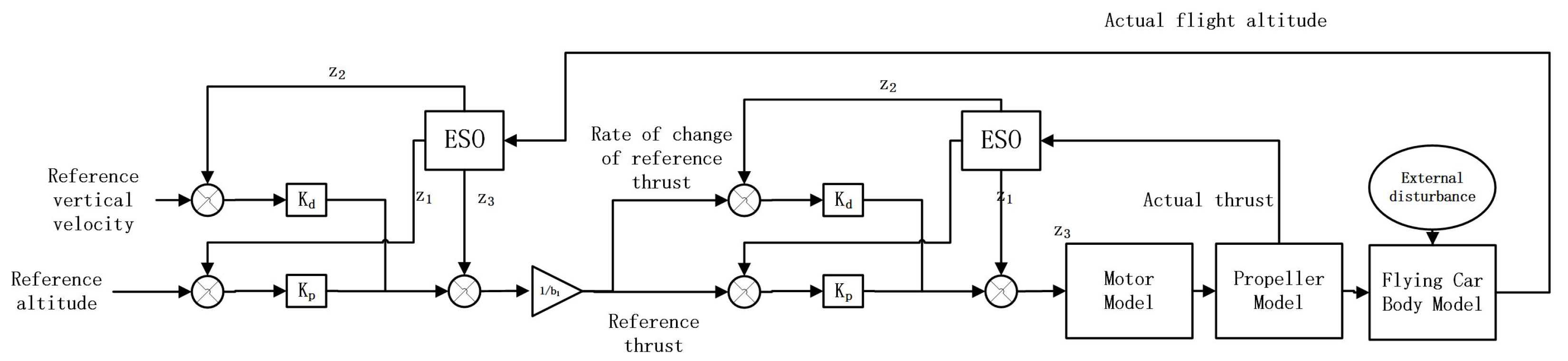
3. Active Disturbance Rejection Controller

As shown in Figure 3, to compensate for the external disturbances, a double-loop controller is designed based on active disturbance rejection control. In the flying car system, the flight altitude is controlled by adjusting the thrust of the propellers, and the rotation speed of the propellers is controlled by the motor. In the proposed controller, the system input of the outer-loop controller is the flight altitude of the flying car. The control input of the outer-loop controller is the thrust of the propeller.s The outer-loop controller calculates the reference thrust for the inner loop. The inner-loop controller controls the rotation speed of the motor. Its control input is the voltage of the motor. It dynamically changes the rotation speed of the motor. Then, using the propeller model, the thrust is transformed into the dynamic model of the flying car to control its flight altitude.
Taking the outer-loop controller as an example, the flight altitude can be expressed as:
h ¨ ( t ) = f ( t , h ( t ) , h ˙ ( t ) , w d t r ( t ) ) + b 1 ( t ) u 1 ( t ) y = h ( t )
where h denotes the flight altitude, b 1 denotes the control gain of the outer-loop controller, u 1 denotes its control input, w d t r denotes the external disturbance, and y denotes the system state.
Firstly, define f = f ( t , h t , h ˙ t , w d t r ( t ) ) , X 1 = [ x 1 , x 2 , x 3 ] T . Equation (22) can be transformed into the form of a state space expression. It is expressed as:
x ˙ 1 ( t ) = x 2 ( t ) x ˙ 2 ( t ) = x 3 ( t ) + b 1 ( t ) u 1 ( t ) x ˙ 3 ( t ) = f ˙ y 1 = x 1 ( t )
where x 3 denotes the total disturbance f, x 1 denotes the flight altitude, and x 2 can be regarded as the vertical velocity.
Based on Equation (23), the extended state observer (ESO) can be built as:
Z ˙ 1 ( t ) = A Z 1 ( t ) + B ( t ) u 1 ( t ) + L 1 y ^ 1 ( t ) y ^ 1 ( t ) = C Z 1 ( t )
A = 0 1 0 0 0 1 0 0 0 , B = 0 b 1 T 0 , C = 1 0 0
where Z 1 = [ z 1 , z 2 , z 3 ] T denotes the observed state, y ^ 1 denotes the sampling value of the system state, T denotes the sampling time, and l = [ l 1 , l 2 , l 3 ] T denotes the observation gain.
It is clear that in ADRC, the main target is to compensate for the total disturbance x 3 , minimizing the error between X 1 and Z 1 . To make sure that the observation error satisfies the upper bound, l i should be set to w o ( w o > 0 ) , which can be expressed by:
λ 0 ( s ) = s 3 + l 1 s 2 + l 2 s + l 3 = ( s + w o ) 3
where l 1 = 3 w o , l 2 = w o 2 , l 3 = w o 3 , with w o denoting the observation bandwidth. Under this condition, the ESO can be built. The states can be accurately observed by the ESO.
Based on this, the control input can be defined as:
u 1 = u 0 z 3 b 1 = k p 1 ( r ( t ) z 1 ( t ) ) + k d 1 ( r ˙ ( t ) z 2 ( t ) ) z 3 b 1
where r denotes the reference flight altitude, k p 1 = 2 w c , and k d 1 = w c 2 . In Equation (27), z 3 is regarded as the total disturbance. Using Equation (27), Equation (22) can be rewritten as:
h ¨ t = f + b 1 u 1 = f + u 0 b 3 u 0
Thus, in Equation (28), the error between z 3 and x 3 can be minimized. This nonlinear system can be regarded as a linear system. Under this condition, its control difficulty can be significantly reduced. It is also the main advantage of the active disturbance rejection control method.
The outer-loop controller can be built based on Equations (22)–(28). The inner-loop controller has a similar structure. However, the reference input of the inner-loop controller, r 2 , is the control input of the outer-loop controller, u 1 . Additionally, based on research on linear ADRC by Prof. Gao [36], the convergence of the observation error and control error of the state can be proven by properly setting w o and w c . With these considerations, the double-loop ADRC controller can be built for altitude control of the flying car.

4. Simulation Verification

So far in this paper, we have built a dynamic model of a flying car and designed a double-loop ADRC controller. In this section, the model and the controller are verified through a detailed simulation and actual experiments.

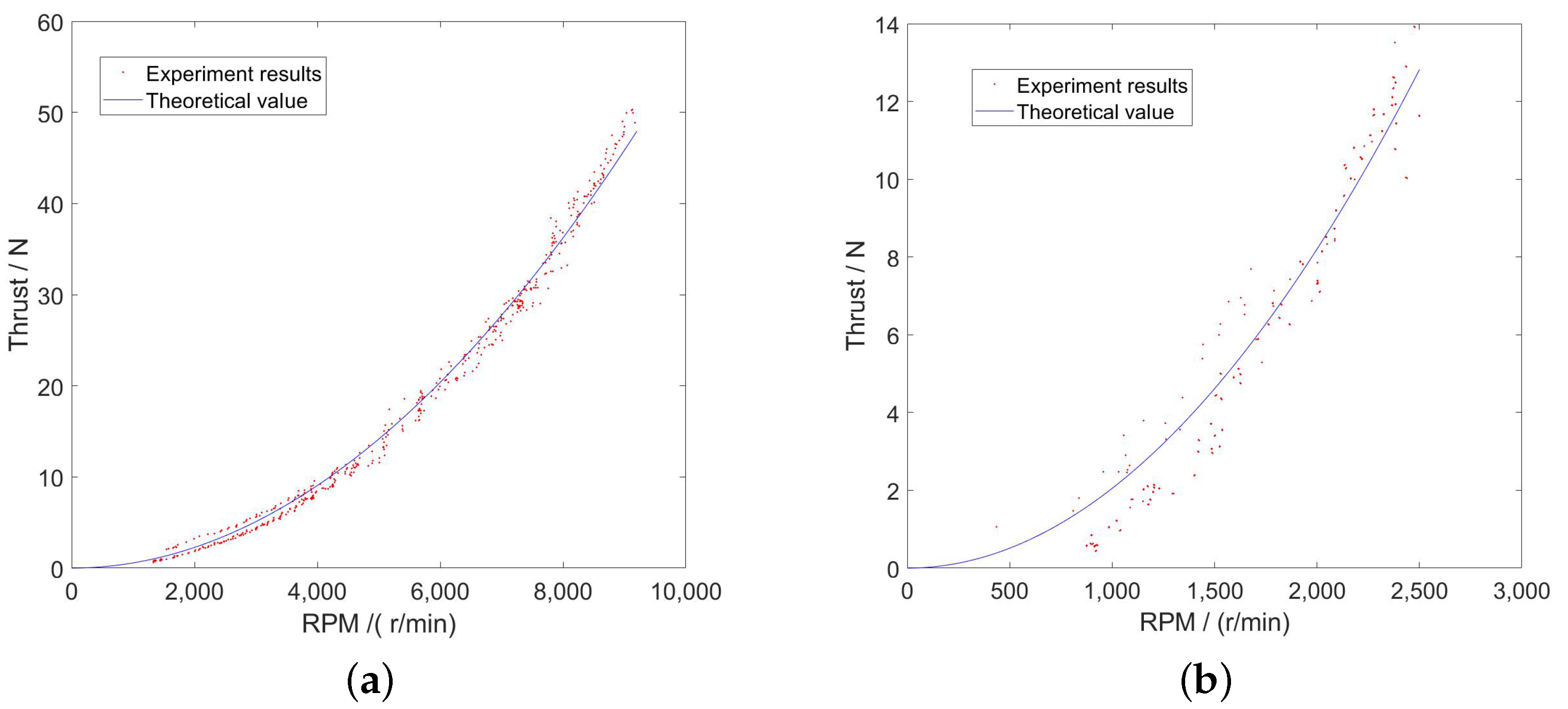
4.1. Verification of the Propeller and Motor Models

Firstly, as shown in Figure 4, we built a platform for thrust verification. The motor and the propeller are set on a thrust-measuring device. The rotation speed of the propeller and its thrust can be dynamically recorded in real time.
The results are depicted in Figure 5, which shows the thrust of the propeller under different rotation speeds. In the actual test, we utilized two different propellers: one was 15 × 8 inches and the other one was 21 × 10 inches. The red points represent the data points of the actual test. The blue lines represent the theoretical values of the thrust in the simulation model.
In Figure 5, it can be clearly seen that the thrust of the propellers can be accurately calculated by the model. The error between the theoretical value and the actual experimental value is very small, thus proving the practicability and validity of the proposed model.
Meanwhile, Figure 6 presents the control effect of the inner-loop controller. The results show that the proposed controller can realize accurate tracking of the rotation speed of the motor.

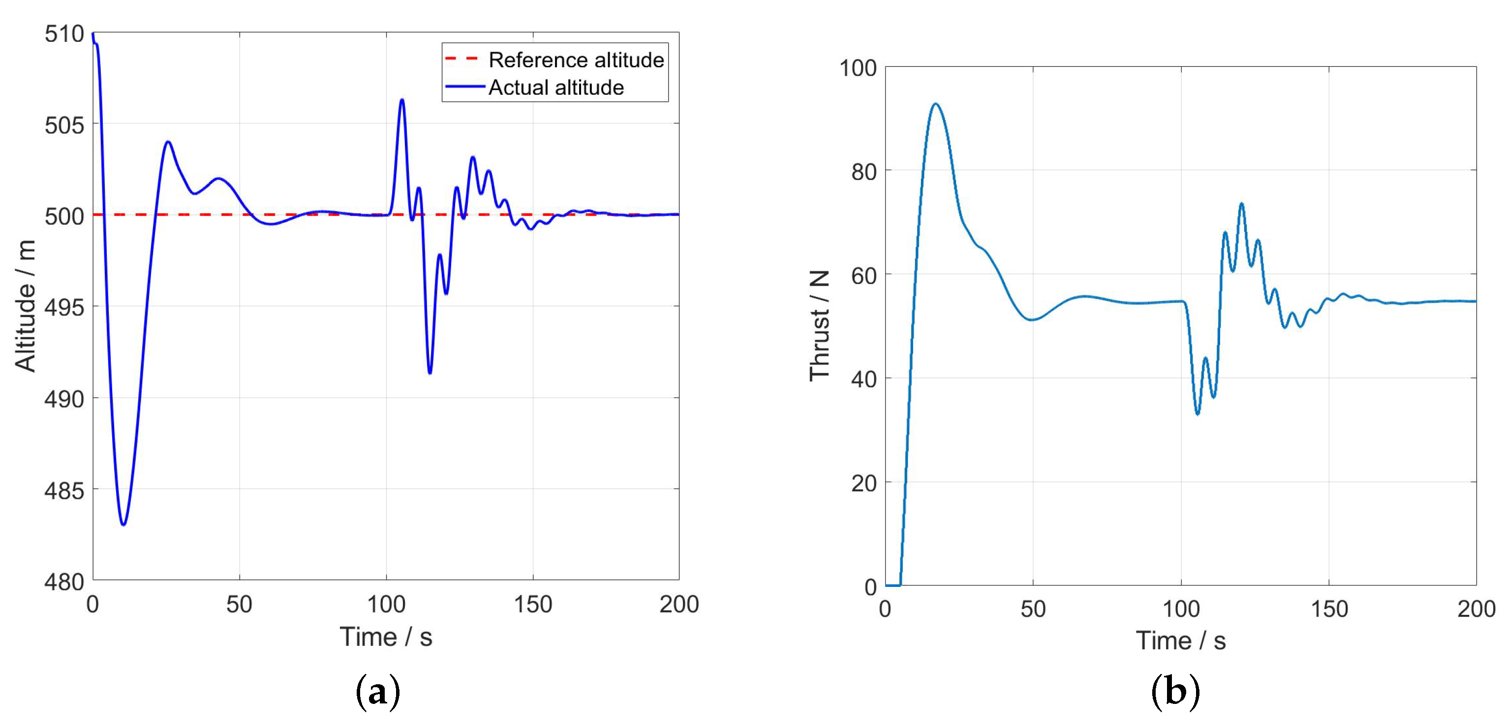
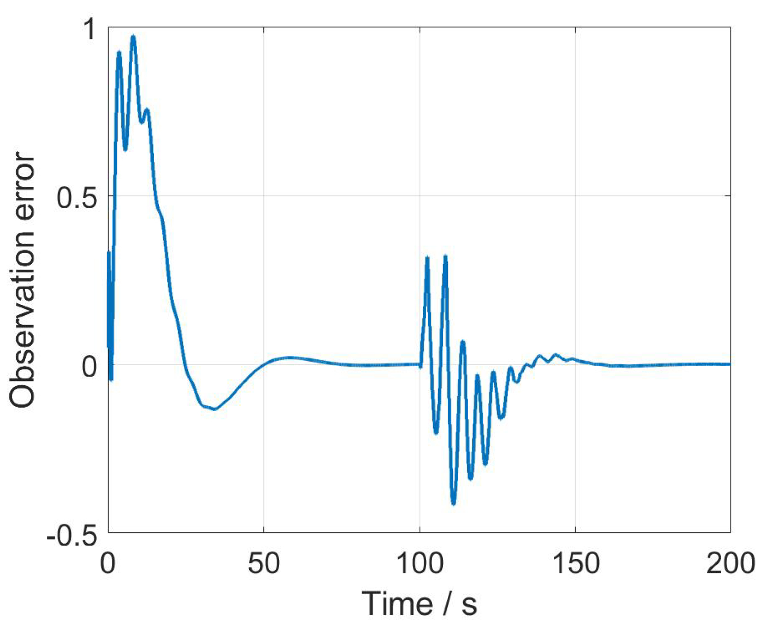
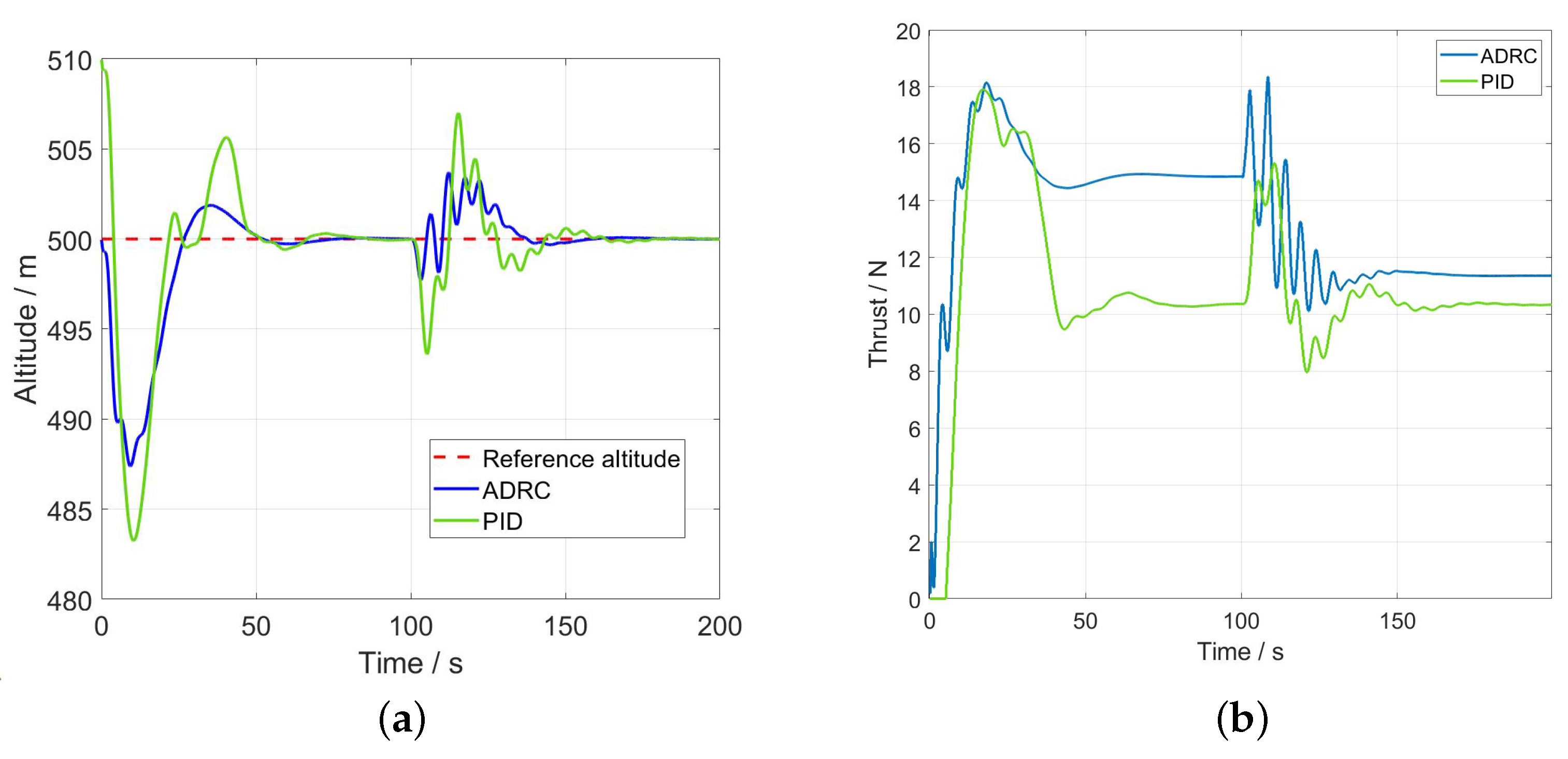
4.2. Altitude Control

After the verification of the model, a simulation of the altitude control of the flying car was carried out. In the simulation, the reference altitude was set at 500 m. The initial altitude of the flying car was set at 510 for the first case and 500 m for the second one. In Case 1, a 4 m/s wind gust was set for 100 s and lasted for 20 s. In Case 2, in addition to the wind gust, a 3 m/s constant wind was also set along the Z-axis of the geodetic coordinate system for 100 s.
The results are presented in Figure 7 and Figure 8. Firstly, in Figure 7, it can be observed that the proposed controller can realize accurate altitude control. Figure 7a shows the flight altitude, and Figure 7b shows the thrust of the propeller. At 100 s, it is obvious that the flight altitude shows some oscillations under the disturbance of the wind gust. However, with the ESO, it can be clearly seen that the control error converges before 140 s. The average error in the stable stage is less than 1 m.
The results of the other simulation case are presented in Figure 8. Figure 8a presents the flight altitude, and the thrust is presented in Figure 8b. In this paper, the proposed controller was compared with a PID controller. The parameters of ADRC were set as ω o , 1 = 0.7 , ω c , 1 = 0.25 , b 1 = 0.17 , ω o , 2 = 1.2 , ω c , 1 = 0.14 , and b 1 = 0.14 . The parameters of the PID controller were set as k p , 1 = 0.6 , k d , 1 = 0.8 , k i , 1 = 0.1 , k p , 2 = 0.4 , k d , 1 = 0.4 , and k i , 1 = 0.1 . It can be seen that the proposed controller can realize accurate trajectory tracking despite wind gusts and constant wind disturbances. The flight altitude of the flying car remains stable and converges to the reference value despite the external wind. From the results, it can be observed that the proposed method has better control effectiveness. Its maximum error is about 20% less than that of the PID controller. Its average error is about 0.6 m, whereas the average error of the PID controller is 0.53 m.
Furthermore, Figure 9 presents the observation error of the outer-loop controller. It can be seen that the observation error converges to zero by accurately adjusting the controller coefficients. Under this condition, accurate altitude control can be realized, dynamically compensating for external disturbances.
Then, to verify the control effectiveness under hardware variations, a Monte Carlo simulation was carried out. The results are shown in Figure 10. In the simulation, the aerodynamic coefficients of the propeller were varied by ± 20 % . It can be seen that the proposed controller can realize accurate control under various hardware conditions. The tracking error can converge within a limited time.

5. Experimental Tests

Finally, based on the detailed simulation cases and model verification, a small platform for the flying car was built. The hardware system is presented in Figure 11a. The external wind was recorded by an anemoscope, as shown in Figure 11b. Based on this platform, an actual flight experiment was carried out. The results are presented in Figure 12 and Figure 13. During the flight test, the proposed method was compared with a PID controller. The reference flight altitude was 6 m.
The flight test using the PID controller is presented in Figure 12. Figure 12a shows the thrust, and Figure 12b presents the flight altitude. The flight time is more than 500 s. It can be observed that both the control input and the flight altitude have large and prolonged oscillations due to unknown external disturbances. Steady-state errors are also present in most experimental times.
The proposed double-loop ADRC controller is presented in Figure 13. The thrust is presented in Figure 13a, and the flight altitude is presented in Figure 13b. It can be seen that when using the proposed method, the flight altitude error of the flying car is much less than that of the PID controller. The error converges at 40 s, which is nearly 60 s faster than with the PID controller. It also has a lower trajectory error. The altitude error is less than 0.1 m. Furthermore, it can be observed that the proposed active disturbance rejection control has a much better capacity to resist disturbances, which further proves the effectiveness of the proposed method.

6. Conclusions

In this paper, to realize accurate altitude control of a flying car, we first built a dynamic model of a flying car comprising a body model, motor model, and propeller model. Then, a double-loop controller based on active disturbance rejection control was designed to accurately control the flight altitude and compensate for unknown external disturbances. Then, detailed simulation results were presented. Through simulation and tests, the model was verified. A simulation of the altitude control was also carried out. In the simulation, the proposed method showed excellent control effectiveness. Finally, based on the detailed simulation results, actual flight tests were carried out. The proposed method was compared with a PID controller. In the flight test, it was observed that the proposed method had better control effectiveness, capacity to resist disturbances, and convergence velocity. The results prove that the proposed method represents a novel method for the altitude control of a flying car and shows broad application prospects.
Besides the disturbances in this paper, there exist time-varying wind disturbances and coupling influences between different propellers. All unknown disturbances need to be considered in the controller design. In future work, we expect to adopt the active disturbance rejection control method. By using an extended state observer, the unknown disturbance can be regarded as an extended state, which can be dynamically compensated for. This is the main research direction for our next work.

Author Contributions

Methodology, W.L. and H.S.; Investigation, J.X.; Resources, Z.L.; Data curation, Y.X.; Funding acquisition, X.L. All authors have read and agreed to the published version of the manuscript.

Funding

This research was funded by the National Natural Science Foundation of China (Grant No. 62003177).

Institutional Review Board Statement

Not applicable.

Informed Consent Statement

Not applicable.

Data Availability Statement

The raw data supporting the conclusions of this article will be made available by the authors on request.

Conflicts of Interest

The authors declare no conflicts of interest. The funders had no role in the design of the study; in the collection, analyses, or interpretation of data; in the writing of the manuscript; or in the decision to publish the results.

References

  1. Kasliwal, A.; Furbush, N.J.; Gawron, J.H.; McBride, J.R.; Wallington, T.J.; De Kleine, R.D.; Kim, H.C.; Keoleian, G.A. Role of flying cars in sustainable mobility. Nat. Commun. 2019, 10, 1555. [Google Scholar] [CrossRef] [PubMed]
  2. Pan, G.; Alouini, M.S. Flying car transportation system: Advances, techniques, and challenges. IEEE Access 2021, 9, 24586–24603. [Google Scholar] [CrossRef]
  3. Rajashekara, K.; Wang, Q.; Matsuse, K. Flying cars: Challenges and propulsion strategies. IEEE Electrif. Mag. 2016, 4, 46–57. [Google Scholar] [CrossRef]
  4. Postorino, M.N.; Sarné, G.M.L. Reinventing mobility paradigms: Flying car scenarios and challenges for urban mobility. Sustainability 2020, 12, 3581. [Google Scholar] [CrossRef]
  5. Swaminathan, N.; Reddy, S.R.P.; RajaShekara, K.; Haran, K.S. Flying cars and evtols—Technology advancements, powertrain architectures, and design. IEEE Trans. Transp. Electrif. 2022, 8, 4105–4117. [Google Scholar] [CrossRef]
  6. Wang, F.; Bai, J.; Yang, L.; Rao, B.; Huang, L. An Overview on Development of Urban Air Traffic with a New Mode of Flying Car Commuting. Trans. Beijing Inst. Technol. 2023, 43, 665–675. [Google Scholar]
  7. Saeed, B.; Gratton, G.B. An evaluation of the historical issues associated with achieving non-helicopter V/STOL capability and the search for the flying car. Aeronaut. J. 2010, 114, 91–102. [Google Scholar] [CrossRef]
  8. Saeed, N.; Al-Naffouri, T.Y.; Alouini, M.S. Wireless communication for flying cars. Front. Commun. Netw. 2021, 2, 689881. [Google Scholar] [CrossRef]
  9. Yang, C.; Lu, Z.; Wang, W.; Wang, M.; Zhao, J. An efficient intelligent energy management strategy based on deep reinforcement learning for hybrid electric flying car. Energy 2023, 280, 128118. [Google Scholar] [CrossRef]
  10. Jiang, H.; Zhou, Y.; Ho, H.W. Aerodynamic design and evaluation of a ducted fan lift system for vertical takeoff and landing flying cars. Proc. Inst. Mech. Eng. Part J. Power Energy 2023, 237, 115–125. [Google Scholar] [CrossRef]
  11. Wang, Y.F.; Su, T.X. Autobody modelling analysis of the flying cars. Appl. Mech. Mater. 2014, 577, 1310–1313. [Google Scholar] [CrossRef]
  12. Zhang, T.; Liu, Y.; Wu, Z.; Li, Z.; Ran, S.; Tian, F. Preliminary Aerodynamic Simulation of a Flying Car Concept. In Proceedings of the 2023 International Conference on Unmanned Aircraft Systems (ICUAS), Warsaw, Poland, 6–9 June 2023; pp. 123–128. [Google Scholar]
  13. Chen, C.; Yang, S.; Chen, F. Simulation Analysis of Aerodynamic Characteristics of Flying Car Based on Bionic Seagull Wing. In Proceedings of the 2022 IEEE International Conference on Robotics and Biomimetics (ROBIO), Xishuangbanna, China, 5–9 December 2022; pp. 1301–1306. [Google Scholar]
  14. Ai, T.; Xu, B.; Xiang, C.; Fan, W.; Zhang, Y. Modeling and multimode analysis of electrically driven flying car. In Proceedings of the 2020 International Conference on Unmanned Aircraft Systems (ICUAS), Athens, Greece, 1–4 September 2020; pp. 1565–1571. [Google Scholar]
  15. Yang, C.; Lu, Z.; Wang, W.; Li, Y.; Chen, Y.; Xu, B. Energy management of hybrid electric propulsion system: Recent progress and a flying car perspective under three-dimensional transportation networks. Green Energy Intell. Transp. 2023, 2, 100061. [Google Scholar] [CrossRef]
  16. Luo, Y.; Qian, Y.; Zeng, Z.; Zhang, Y. Simulation and analysis of operating characteristics of power battery for flying car utilization. eTransportation 2021, 8, 100111. [Google Scholar] [CrossRef]
  17. Gur, O.; Rosen, A. Optimization of propeller based propulsion system. J. Aircr. 2009, 46, 95–106. [Google Scholar] [CrossRef]
  18. Moelyadi, M.A. Development of Flying Car Model with Quad Rotors. J. Unmanned Syst. Technol. 2015, 3, 1–5. [Google Scholar]
  19. Wang, S.; Li, J.; Gao, X.; Yan, B.H. Conceptual Design of Four Rotors Flying Car Based on Bionics. In Proceedings of the 2017 5th International Conference on Mechatronics, Materials, Chemistry and Computer Engineering (ICMMCCE 2017), Chongqing, China, 24–25 July 2017; Atlantis Press: Amsterdam, The Netherlands, 2018; pp. 928–933. [Google Scholar]
  20. Takii, A.; Gomi, R.; Yamakawa, M.; Tsubokura, M. Turning Flight Simulation with Fluid-Rigid Body Interaction for Flying Car with Contra-Rotating Propellers. In Proceedings of the International Conference on Computational Science, Prague, Czech Republic, 3–5 July 2023; Springer Nature: Cham, Switzerland, 2023; pp. 566–577. [Google Scholar]
  21. Mihara, Y.; Nakamura, T.; Nakamoto, A.; Nakano, M. Airframe design optimization and simulation of a flying car for medical emergencies. Int. J. Autom. Technol. 2022, 16, 183–196. [Google Scholar] [CrossRef]
  22. Kim, K.; Hwang, K.; Kim, H. Study of an adaptive fuzzy algorithm to control a rectangular-shaped unmanned surveillance flying car. J. Mech. Sci. Technol. 2013, 27, 2477–2486. [Google Scholar] [CrossRef]
  23. Pardede, W.M.; Adhitya, M. Take off and landing performance analysis for a flying car model using wind tunnel test method. In Proceedings of the AIP Conference Proceedings, Padang, India, 22–24 July 2020; AIP Publishing: Melville, NY, USA, 2020; p. 2227. [Google Scholar]
  24. Shi, X.; Kim, K.; Rahili, S.; Chung, S.J. Nonlinear control of autonomous flying cars with wings and distributed electric propulsion. In Proceedings of the 2018 IEEE Conference on Decision and Control (CDC), Miami Beach, FL, USA, 17–19 December 2018; pp. 5326–5333. [Google Scholar]
  25. Takahashi, N.; Gomi, R.; Takii, A.; Yamakawa, M.; Asao, S.; Takeuchi, S. Numerical Simulation of the Octorotor Flying Car in Sudden Rotor Stop. In Proceedings of the International Conference on Computational Science, Prague, Czech Republic, 3–5 July 2023; Springer Nature: Cham, Switzerland, 2023; pp. 33–46. [Google Scholar]
  26. Ruan, S.; Ma, Y.; Wei, Z.; Yang, N.; Zhang, C.; Xiang, C. Hierarchical Control Strategy for the Hybrid Electric Propulsion System of a Flying Car with Engine Start-Stop System and Dynamic Coordination. IEEE Trans. Transp. Electrif. 2023. [Google Scholar] [CrossRef]
  27. Trancossi, M.; Hussain, M.; Shivesh, S.; Pascoa, J. A new VTOL propelled wing for flying cars: Critical bibliographic analysis. SAE Tech. Pap. 2017, 1, 1–14. [Google Scholar]
  28. Bae, H.; Lee, J.; Lee, K. Marker-Based 3D Position-Prediction Algorithm of Mobile Vertiport for Cabin-Delivery Mechanism of Dual-Mode Flying Car. Electronics 2022, 11, 1837. [Google Scholar] [CrossRef]
  29. Tanjim, M.S.S.; Oishi, A.N.; Nandy, A.; Jannah, R.; Ahmed, S. A flight control system for a vehicle. In Proceedings of the 2019 International Conference on Robotics, Electrical and Signal Processing Techniques (ICREST), Dhaka, Bangladesh, 10–12 January 2019; pp. 313–318. [Google Scholar]
  30. Han, J. From PID to active disturbance rejection control. IEEE Trans. Ind. Electron. 2009, 56, 900–906. [Google Scholar] [CrossRef]
  31. Feng, H.; Guo, B.Z. Active disturbance rejection control: Old and new results. Annu. Rev. Control. 2017, 44, 238–248. [Google Scholar] [CrossRef]
  32. Huang, Y.; Xue, W. Active disturbance rejection control: Methodology and theoretical analysis. ISA Trans. 2014, 53, 963–976. [Google Scholar] [CrossRef] [PubMed]
  33. Ahi, B.; Haeri, M. Linear active disturbance rejection control from the practical aspects. IEEE/Asme Trans. Mechatronics 2018, 23, 2909–2919. [Google Scholar] [CrossRef]
  34. Tan, W.; Fu, C. Linear active disturbance-rejection control: Analysis and tuning via IMC. IEEE Trans. Ind. Electron. 2015, 63, 2350–2359. [Google Scholar] [CrossRef]
  35. Ahmad, S.; Ali, A. On active disturbance rejection control in presence of measurement noise. IEEE Trans. Ind. Electron. 2021, 69, 11600–11610. [Google Scholar] [CrossRef]
  36. Gao, Z. Active disturbance rejection control: From an enduring idea to an emerging technology. In Proceedings of the 2015 10th International Workshop on Robot Motion and Control (RoMoCo), Poznan, Poland, 6–8 July 2015; pp. 269–282. [Google Scholar]
  37. Gupte, S.; Mohandas, P.I.T.; Conrad, J.M. A survey of quadrotor unmanned aerial vehicles. In Proceedings of the 2012 Proceedings of IEEE Southeastcon, Orlando, FL, USA, 15–18 March 2012; pp. 1–6. [Google Scholar]
  38. Alexis, K.; Nikolakopoulos, G.; Tzes, A. Model predictive quadrotor control: Attitude, altitude and position experimental studies. IET Control. Theory Appl. 2012, 6, 1812–1827. [Google Scholar] [CrossRef]
  39. Fernando, H.; De Silva, A.T.A.; De Zoysa, M.D.C.; Dilshan, K.D.C.; Munasinghe, S.R. Modelling, simulation and implementation of a quadrotor UAV. In Proceedings of the 2013 IEEE 8th International Conference on Industrial and Information Systems, Kandy, Sri Lanka, 17–20 December 2013; pp. 207–212. [Google Scholar]
  40. Chen, M.; Xiong, S.; Wu, Q. Tracking flight control of quadrotor based on disturbance observer. IEEE Trans. Syst. Man Cybern. Syst. 2019, 51, 1414–1423. [Google Scholar] [CrossRef]
  41. Islam, S.; Liu, P.X.; El Saddik, A. Robust control of four-rotor unmanned aerial vehicle with disturbance uncertainty. IEEE Trans. Ind. Electron. 2014, 62, 1563–1571. [Google Scholar] [CrossRef]
Figure 1. Structure of a flying car. (a) Top of the flying car with the propellers folded up; (b) Top of the flying car with the propellers unfolded; (c) Structure of the flying car with the propellers folded up; (d) Structure of the flying car with the propellers unfolded.
Applsci 14 02754 g001
Figure 2. Force analysis of a flying car.
Applsci 14 02754 g002
Figure 3. Double-loop controller based on active disturbance rejection control.
Applsci 14 02754 g003
Figure 4. Thrust verification equipment and experiment.
Applsci 14 02754 g004
Figure 5. Data comparison of the thrust with different propellers. (a) Propeller: 15 × 8 inches. (b) Propeller: 21 × 10 inches.
Applsci 14 02754 g005
Figure 6. Verification of the motor.
Applsci 14 02754 g006
Figure 7. Altitude control with external wind disturbance—Case 1. (a) Flight altitude. (b) Thrust.
Applsci 14 02754 g007
Figure 8. Altitude control of the ADRC and PID controllers. (a) Flight altitude. (b) Thrust.
Applsci 14 02754 g008
Figure 9. Observation error.
Applsci 14 02754 g009
Figure 10. Monte Carlo simulation with various aerodynamic coefficients.
Applsci 14 02754 g010
Figure 11. Hardware of the flying car. (a) Flying car. (b) External wind disturbance.
Applsci 14 02754 g011
Figure 12. Flight experiment using the PID controller for altitude control. (a) Thrust. (b) Flight altitude.
Applsci 14 02754 g012
Figure 13. Flight experiment using the proposed method for altitude control. (a) Thrust. (b) Flight altitude.
Applsci 14 02754 g013
Disclaimer/Publisher’s Note: The statements, opinions and data contained in all publications are solely those of the individual author(s) and contributor(s) and not of MDPI and/or the editor(s). MDPI and/or the editor(s) disclaim responsibility for any injury to people or property resulting from any ideas, methods, instructions or products referred to in the content.

