Article

Design and Analysis of a Novel Variable Stiffness Joint Based on Leaf Springs

Henan Key Laboratory of Intelligent Manufacturing of Mechanical Equipment, Zhengzhou University of Light Industry, Zhengzhou 450002, China
*
Author to whom correspondence should be addressed.
Appl. Sci. 2024, 14(7), 2685; https://doi.org/10.3390/app14072685
Submission received: 27 February 2024 / Revised: 20 March 2024 / Accepted: 20 March 2024 / Published: 22 March 2024
(This article belongs to the Special Issue Advances in Modeling, Identification, and Control of Robotics)

Abstract

:
In response to challenges like the complexity and limited scalability of existing variable stiffness joints, a novel variable stiffness joint, based on leaf spring elements, is introduced in this paper. The joint stiffness can be adjusted in real time by changing the effective length of the leaf spring via the use of an Archimedean spiral groove. The stiffness adjustment range and load capacity of the joint can be defined by manually configuring the number of springs involved during offline joint operations. A stiffness model for the joint is established based on the cantilever beam theory of material mechanics. The coupled effects of the design parameters of the variable stiffness mechanism on joint stiffness, elastic torque, and stiffness adjustment resistance torque are analyzed. A dynamic model for the joint is developed, while a PID controller is designed for simulation purposes. The motion characteristics of the joint are analyzed, confirming that this approach has certain advantages in terms of stiffness adjustment speed and accuracy.

1. Introduction

As the operation of interactive robots coexisting and working in the same space as humans grows in popularity, issues of safety and compliance have become quite urgent for this field of technology [1]. The introduction of series elastic joints has provided a mitigating solution for this challenge. This approach achieves expected physical interaction behaviors by combining elastic elements in series in the robot joint transmission chain with a specific indirect force control method [2]. Due to the inherent compliance of elastic elements, joints equipped with in series elastic joints can dampen impacts, absorb collision energy, and ensure safety during the interaction process [3]. However, the fixed stiffness of in series elastic joints cannot reconcile the inherent contradiction between force control precision and mechanical impedance, resulting in a lower bandwidth for compliant control, as well as the limited flexibility of robot joints in complex environments [4].
In response to this limitation, the variable stiffness joint (VSJ) has been proposed. The design of the VSJ is achieved by adding a variable stiffness mechanism (VSM), based on a series of elastic joints. This mechanism actively adjusts the output stiffness during the dynamic motion process of the joint in either an independent or coupled manner [5], thereby enhancing joint effective bandwidth, output power, and positioning accuracy in order to meet the requirements of different environments and tasks. According to the relative arrangement of the main drive and stiffness adjustment motor, VSJs can be categorized into two main types: antagonistic layout and independent layout [6].
Inspiration for the design of VSJs with antagonistic layouts is drawn from the drive modes of biological limbs [7]. In this design, a pair of non-linear springs are connected to the two ends of the driver in an antagonistic layout. Nonlinear stiffness on the output shaft of the joint is produced by stretching a pair of symmetrically placed springs in either the same or opposite directions [6]. Joints that follow this design include CETs-VSA [8] and SPVSA [9], which are advantageous in terms of strong adaptive motion control and better simulations of the dynamic behavior of human joints. However, the coupled motion of the two motors results in complex controls [10].
In the case of the independent layout of VSJs, there are various methods to change the joint stiffness. Changing the spring preload is a strategy where the driver stiffness is regulated by altering the spring force received during deformation via the adjustment of the initial deformation of the spring. The mechanical adjustable compliant controllable equilibrium position actuator (MACCEPA) is a representative example [11]. Meanwhile, the floating spring joint (FSJ) [12], the bidirectional antagonistic floating spring actuator (BAFSA) [13], the lightweight variable stiffness actuator (LVSA) [14], and the reconfigurable variable stiffness actuator (RVSA) [15] are all based on this scheme. However, the regulation of the spring compression amount (determining the stiffness characteristics) depends on the cam profile curve. The cam profile curve is based on the stiffness adjustment mechanism of the cam device, which increases the complexity of stiffness calculations and control [16], while joint compliance is adjusted by changing the preload of the elastic element, which then results in high energy consumption and high resistance to adjustment [17].
In the case of a VSA, stiffness adjustment can also be achieved by introducing a variable lever mechanism between the elastic element and the load connection point. Specifically, the compression of the spring can be dynamically adjusted by changing the point of action of the elastic element on the lever, the load connection point [18], or the lever fulcrum [19], thereby adjusting the output stiffness of the driver. Based on this principle, researchers have proposed various VSMs, such as the variable stiffness actuator vsaUT-II [20], the pseudo-linear variable ratio lever variable stiffness actuator (PLVL-VSA) [21], a rotational joint actuator based on the mechanism of a flexible rack and gear (vsaFGR) [22], the variable stiffness actuator based on a rocker-linked epicyclic geartrain (REGT-VSA) [23], and the variable stiffness actuator based on a second-order lever mechanism [24], among others. In these VSMs, flexible rack mechanisms, planetary gear mechanisms, or linkages mechanisms are used to adjust the position of the lever fulcrum. However, the introduction of these mechanisms causes the entire joint to be too complex and bulky. The method of changing the lever fulcrum position via the use of an Archimedes spiral displacement mechanism alleviates this limitation [25].
In the above stiffness adjustment methods, the physical parameters of the flexible element itself are not changed during the adjustment process, while changing the effective length of the elastic element is a common practice to achieve stiffness adjustment. Typical examples include the parallel double-motor compliant VSJ [26], the mechanical rotary variable impedance actuator (MeRIA) [27], the vsaSDR designed in combination with Archimedes spiral [28], and the variable stiffness actuator based on a cam-leaf spring mechanism (CLSM-VSA) [29], among others. However, in most current designs, the adjustment of the effective length of the elastic element is often achieved using ball screws, gears, or linkages, which can often complicate the joint design, and can only provide a single stiffness range, which is not effective for certain application scenarios. Therefore, joints with reconfigurable capabilities have been developed, whereas the number of plate springs can be reconfigured in the joint LSVSJ [30] to achieve stiffness adjustments across different ranges. However, its stiffness adjustment depends on the manual operation and its load capacity, which is often quite low. The reconfigurable variable stiffness brake RVSA [31] can successfully execute stiffness reconstructions and online adjustments; however, each reconstruction requires the disassembly of the entire joint structure, which can have an adverse effect on its accuracy.
In addition to traditional driving methods, new approaches based on the characteristics of the applied materials are receiving more and more attention, such as shape memory alloys (SMA) [32], dielectric elastomers [33], magnetorheological fluids [34], etc. Based on this principle, different drivers have been developed, such as linear digital variable stiffness actuator (LDVSA) [35], bionic variable stiffness dielectric elastomer actuator (VSDEA) [36], and magnetorheological fluid variable stiffness driver (VSAMF) [37].
In this paper, a novel reconfigurable VSJ is designed. The joint uses an arc-shaped groove to continuously adjust the stiffness, while a reconfiguration mechanism is designed for use within the joint in order to calculate the number of leaf springs. Discrete stiffness changes can be achieved by simply adjusting the number of leaf springs, thereby providing a wider range of stiffness and load capacities, enabling various working conditions to be met.
The remaining chapters of this paper are organized as follows: Section 2 introduces the principle of stiffness adjustment for VSJs, the stiffness model, and joint characteristics. In Section 3, the structure of the VSJ is introduced. In Section 4, simulation analysis and performance evaluation of the joint are conducted. Finally, the conclusions of the paper and potential future works are presented in Section 5.

2. Principle of the VSJ

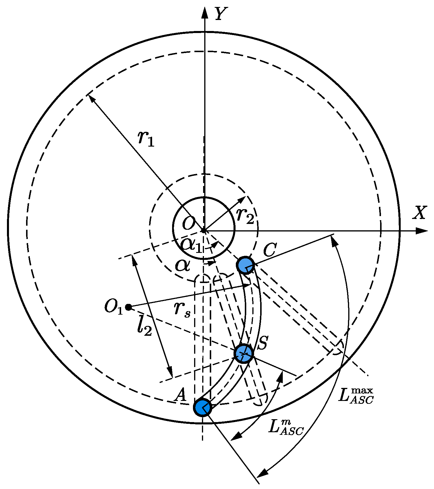
2.1. Analysis of Stiffness Regulation Principles

The proposed working principle of VSJs is shown in Figure 1. The VSM mainly consists of an input shaft (the area where the dashed and thin curves are located), leaf springs, and an output shaft, connected in series. One end of the leaf spring is fixed to the output shaft’s chuck, and the other end is free, thus forming a cantilever beam structure. By adjusting the distance between the slider (connected to the input shaft) and the fixed end of the leaf spring, the effective length of the leaf spring participating in the transmission can easily be changed, thereby adjusting the stiffness between the input and output sides of the entire VSJ. From a theoretical perspective, when the slider is at the free end of the leaf spring, the stiffness of the VSJ is at its minimum, while the elastic deflection (maximum deflection) is at its maximum. As the slider is adjusted towards the fixed end of the leaf spring, the length of the leaf spring involved in the actual transmission gradually decreases, and the output stiffness of the VSJ gradually increases. When the slider moves to the fixed end of the leaf spring, the effective length of the leaf spring involved in the transmission can be considered to be equal to zero. At this point, the input shaft and the output shaft are equal in terms of the effect of the rigid gear transmission, whereas its compliance is the lowest. Furthermore, by arranging multiple leaf spring parts (connected in parallel) uniformly around the output axis, not only can the minimum stiffness value be changed (changing the tuning bandwidth), but the load capacity of the entire VSJ can also be improved, thereby acquiring certain reconfigurable characteristics. This bears important positive significance for the VSJ to adapt to application scenarios involving different loads [38].

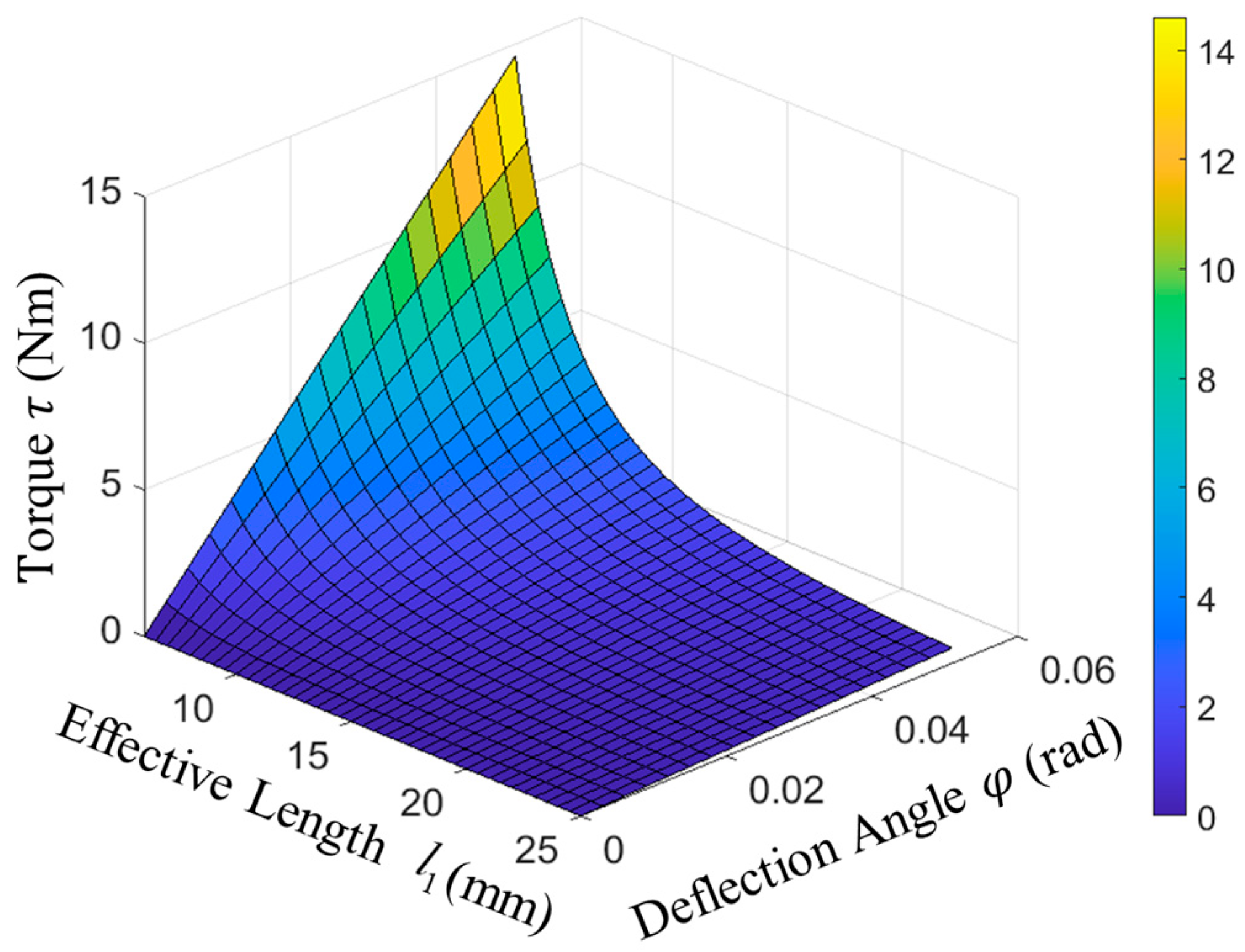
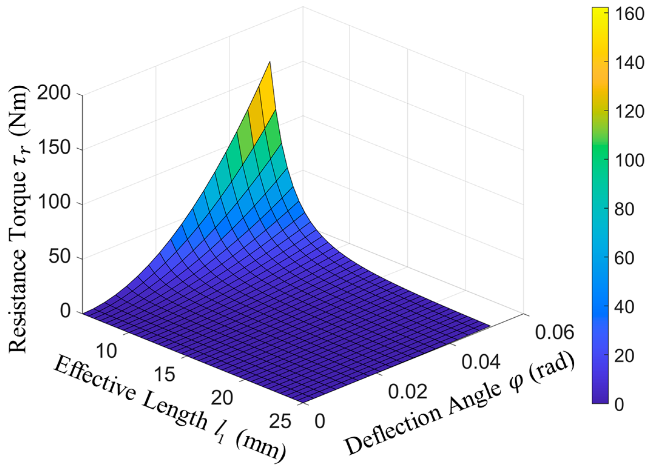
2.2. Stiffness Model

Referring to Figure 1, in the small deformation hypothesis, the deformation of the leaf spring is approximately defined by the geometric relationship as
ω = l 2 tan φ
where l 2 is the distance from the slider to the output shaft, and φ is the deflection angle of the VSJ input shaft relative to its output shaft.
The effective length of the leaf spring can be changed by moving the slider along the leaf spring. According to Hooke’s law and the small deformation cantilever beam model, the deflection of the leaf spring at the contact point with the slider, as well as the deformation angle θ of the leaf spring at the free end relative to the initial position, are defined as
ω = F l 1 3 / ( 3 E I ) θ = F l 1 2 / ( 2 E I )
where F is the force applied to the leaf spring from the slider, l 1 is the distance from the slider to the leaf spring holder, and E is the Young’s modulus of the leaf spring.
It is worth mentioning that, although large deflection of the leaf spring can help improve the reverse drive and passive elastic energy performance of the joint actuator, the large deflection theory of a cantilever beam is complex, and the beam spring is prone to fatigue damage under large deformation, which can lead to an increase in the hysteresis of elastic deformation. This could also even lead to a large transmission backlash in the actuator, which is not conducive for compliant operation. Therefore, based on experience and design parameters, in order to meet the assumption of small spring deformation, avoid model nonlinear deviation during large deformation, and reduce the hysteresis effect of spring deformation, θ is limited to a conservative range where θ < 10 o , which can easily be ensured via mechanical limiting in the prototype.
By combining Equations (1) and (2), the concentration force on the free end can be derived by the following equation:
F = 3 E I l 2 tan φ l 1 3
where I is the moment of inertia of the leaf spring section, defined as
I = b h 3 12
where b and h are the width and thickness of the leaf spring, respectively.
By combining Equations (3) and (4), the concentration force on the free end can be rewritten as follows:
F = E b h 3 l 2 tan φ 4 l 1 3
The designed VSJ is a rotational joint, composed of N parallel leaf springs. The elastic torque τ acting on the joint can be calculated as follows:
τ = N F l 2 cos φ
By combining Equations (5) and (6), the elastic torque can be defined as
τ = N E b h 3 l 2 2 sin φ 4 l 1 3
The stiffness of the VSJ is given as
K = d τ d φ
Therefore, by combining Equations (7) and (8), the total stiffness of the VSJ can be approximated as
K = N E b h 3 l 2 2 cos φ 4 l 1 3
When the VSJ is subjected to an external load, the elastic deflection between the input and output shafts will be equivalent to the elastic potential energy. This energy, which will be expected to be reused in some cyclic motion cases, is defined as
V = 0 θ τ d φ = E b h 3 l 2 2 4 l 1 3 ( 1 cos φ )
When the elastic deflection angle is not zero, stiffness adjustment requires the stiffness motor to overcome resistant torque τ r , which is defined as follows:
τ r = d V d l 1
l 2 = r 2 + l 1 , r 2 is the distance from the leaf spring holder to the center axis of the output shaft. By combining Equations (10) and (11), τ r is calculated as follows:
τ r = E b h 3 ( 1 cos φ ) 4 l 1 2 + 4 r 2 l 1 + 3 r 2 2 l 1 4

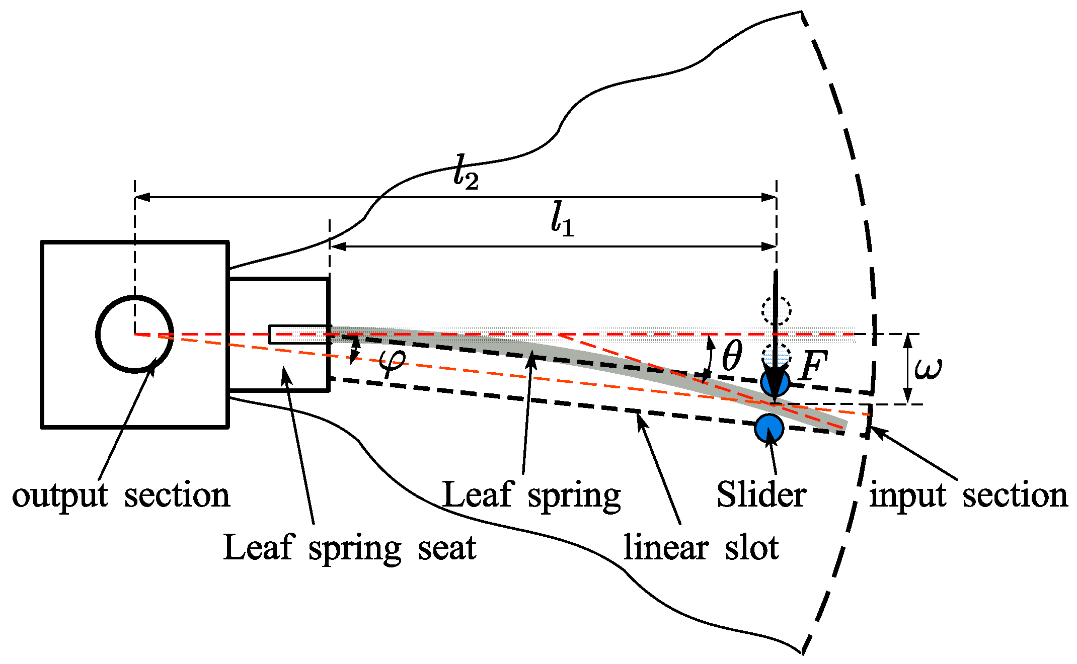
2.3. Design of Stiffness Adjustment Mechanism

The working principle of the leaf spring effective length adjustment mechanism is shown in Figure 2. The position of the shift lever is determined by the intersection point of the straight rail on the drive disk and the arc-shaped rail on the stiffness varying disk. The adjustment of the effective working length of the leaf spring is achieved by changing the radial position of the shift lever across the entire joint diameter. The radial movement of the shift lever is driven by the rotational motion of the stiffness varying disk. The leaf spring effective working length is determined by the rotation angle of the adjustment plate, meaning it is necessary to establish the corresponding relationship between the radial displacement of the transmission pawl and the rotation angle of the adjustment plate. The symbols in Figure 2 are defined as listed in Table 1. Point A, S, and C are placed on the arc A S C with the center point O 1 . Based on geometric relationships, this can be derived using the following equation:
o x o 1 2 + r 2 y 01 2 = r s 2 l 2 sin α x o 1 2 + l 2 cos α y 01 2 = r s 2 r 1 sin α 1 x o 1 2 + r 1 c o s α 1 y o 1 2 = r s 2
Furthermore,
y 01 = e 1 e 2 + r 2 e 2 2 + 1 + e 1 e 2 + r 2 2 e 2 2 + 1 2 e 1 2 + r 2 2 r s 2 e 2 2 + 1 x o 1 = e 1 + e 2 y o 1
where e 1 = r 2 2 r 1 2 2 r 1 sin α 1 and e 2 = r 2 l 2 cos α 1 r 1 sin α 1 .
The distance l 2 from the slider to the output shaft center can be represented as follows:
l 2 = e 3 + e 3 2 e 4
where e 3 = x o 1 sin α y 01 cos α and e 4 = x 01 2 + y 01 2 r s 2 .
The complexity of the arc groove curve determines the positioning accuracy, stability, and response speed of the adjustment process. In order to reduce the complexity of the VSM adjustment control, it is necessary to simplify Equation (13) and obtain the fitted function as follows [39]:
l 1 = p α + q
where p and q are the circular arc parameters of the adjustment disk.
Figure 2. Schematic diagram of the effective length adjustment mechanism for leaf spring.
Applsci 14 02685 g002
Table 1. Symbol definition.
SymbolDefinition
Othe center position of the stiffness regulation disc
O 1 the center position of the arcuate slots
( x 01 , y 01 )the abscissa and ordinate of the point of O 1
A, S, Cthe position of the slider
L A S C 0 , L A S C m , L A S C max the arc length of the slider
(0, r 2 )the coordinates of A
( l 2 sin α , l 2 cos α )the coordinates of S
( r 1 sin α 1 , r 1 c o s α 1 )the coordinates of C
r 1 the distance between the origin O and the point C
l 2 the distance between the origin O and the point S
r 2 the distance between the origin O and the point A
α the angle between the line O A ¯ and the line O S ¯
α 1 the angle between the line O A ¯ and the line O C ¯

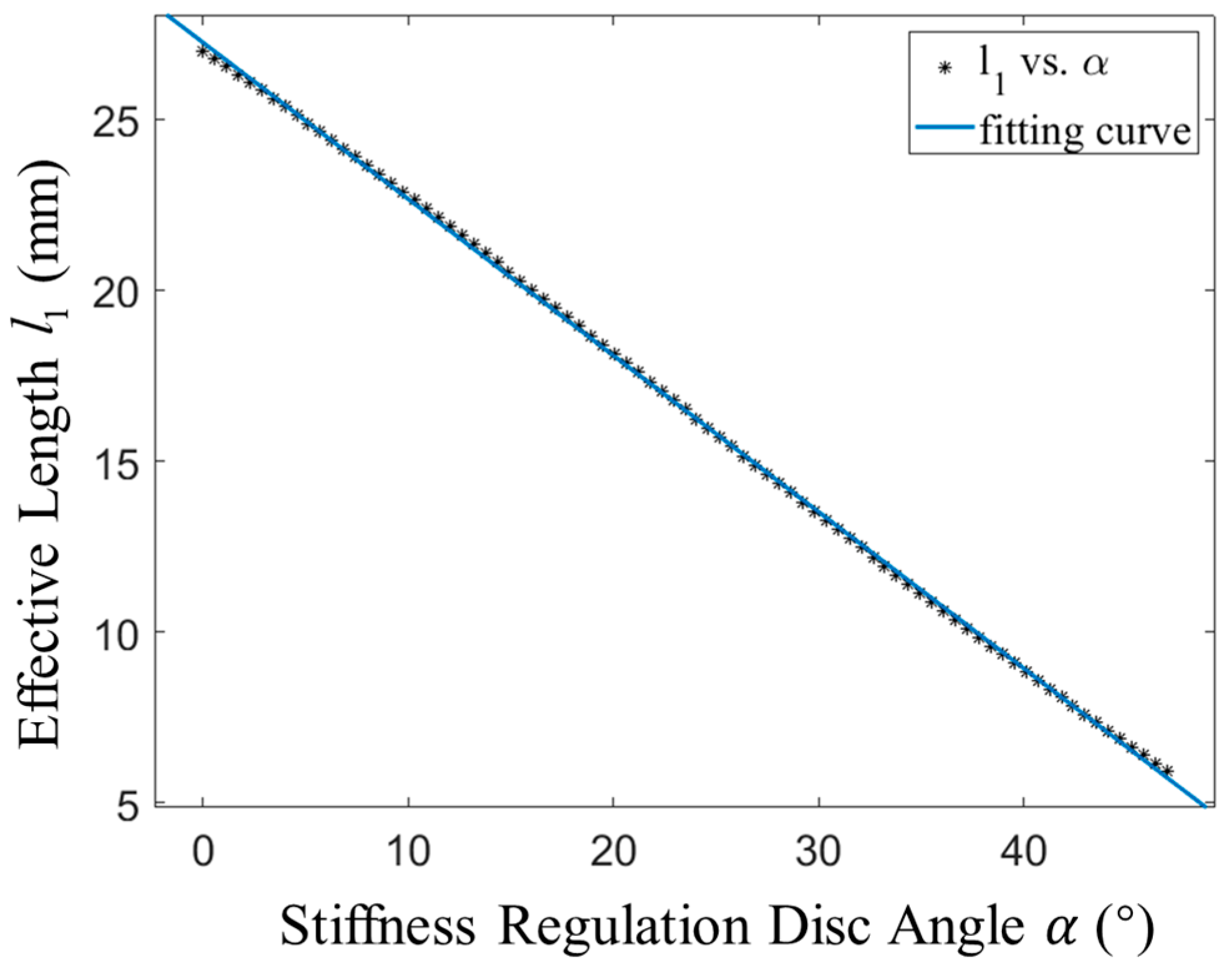
2.4. Performance Analysis of Stiffness Adjustment Mechanism

Based on Equations (7)–(12), the performance of the VSJ is related to the number, width, and thickness of the leaf springs, the length of the joint rotation moment arm, the effective force arm length of the leaf springs, as well as the joint deflection angle. Once the parameters, such as N, b, h, and r 2 , are completely determined, the stiffness adjustment performance of the joint is influenced by the effective arm length of the leaf spring and the joint rotation angle. The theoretical simulation analysis of the variable stiffness characteristics of the joint was performed using Matlab software (R2019a) in order to understand their mutual changes, thus providing a basis for subsequent VSJ structure designs and optimization. The design parameters of the VSJ required for simulation can be found in Table 2.
According to Equation (9), when the output part of the joint is subjected to a load, it will undergo elastic deflection. The joint stiffness is collaboratively constrained by the effective length of the leaf spring and the deflection angle. The stiffness characteristics of the joint are illustrated in Figure 3, where one can see that the longer the effective arm length of the leaf spring, the lower the output stiffness. Meanwhile, the influence of the joint deflection angle on the output stiffness is relatively small. Figure 4 shows the relationship between the output stiffness and the deflection angle under the different effective arm lengths of the leaf spring. It is demonstrated that the output stiffness hardly changes with the change of joint deflection angle, while it can be approximately considered that the output stiffness of the joint is solely determined by the arm length of the spring leaf. This represents a weak coupling between the load and the VSJ stiffness, which is conducive to motion control.
According to Equation (16), when the stiffness adjustment motor regulates the rotation angle θ of the stiffness adjustment disk, the effective length l of the leaf spring approximately changes in a linear manner, as shown in Figure 5. This will help reduce the complexity of the stiffness adjustment process and improve the response speed of this adjustment. At the same time, according to Equation (9), as the effective length of the leaf spring increases, the joint stiffness demonstrates a nonlinear trend. It is evident that, when the effective length of the leaf spring is approximately zero, the joint stiffness approaches infinity. The joint stiffness changes dramatically when the effective length of the leaf spring is within the range of 0–6 mm. Although a high stiffness adjustment speed was demonstrated, from the application point of view, the stiffness adjustment resolution decreased sharply within this range, whereas its adjustment was almost meaningless. Therefore, the effective adjustment range of the leaf spring is set to be 6–25 mm, while the limit rotation angle of the corresponding stiffness adjustment disk is set to 47°. As shown in Figure 6, the output stiffness of the VSJ decreases nonlinearly as the effective length of the leaf spring increases. The theoretical stiffness range is about 9–inf. Nm/rad. The shaded area surrounded by pink lines represents an area with relatively slow stiffness changes, and the stiffness adjustment accuracy in this area is relatively high.
The relationship between the elastic torque and the effective arm length of the leaf spring can be obtained via Equation (7). Figure 7 illustrates this, along with the elastic deflection angle of the joint. Unlike the output stiffness of the joint, the elastic deflection angle of the joint has a significant influence on the elastic torque, especially when the effective length of the leaf spring is relatively small, which is more prominent. In Figure 7, the x-axis coordinate starts from 6 mm, because when l approaches infinity, the stiffness value also approaches infinity, while the elastic torque of the VSJ also theoretically tends to infinity. However, this situation is not a realistic scenario, because the stiffness of the VSJ depends on the structural strength, and there is a high risk of damage due to overload.
The elastic mechanism of VSJ can store energy in periodic motions, and then repeatedly reuse part of this energy in order to achieve energy-efficient motion control and shock absorption. This feature has great potential in applications of periodic motion control and in physical interaction shock absorption. The elastic potential energy of the VSJ joint under different deflection amounts can be obtained using Equation (10). Its characteristics are shown in Figure 8. It is easy to conclude that the joint potential energy increases as the effective length of the leaf spring decreases, whereas a positive correlation with the change of the joint deflection angle is also clear. When the elastic deflection angle of the joint is close to zero, the joint potential energy is minimized.
According to Equation (12), under the coupling effect of the effective length and elastic deflection angle of the leaf spring, to overcome the elastic potential energy under different elastic deflection states is necessary, particularly when the leaf spring has different lengths during stiffness adjustments. The changes in the stiffness adjustment resistance torque of the VSM are shown in Figure 9. Evidently, the changes in the effective length of the leaf spring and the elastic deflection angle of the joint have significant nonlinear effects on the required stiffness adjustment resistance torque. The specific mechanism design of VSJs must reduce this adverse effect.

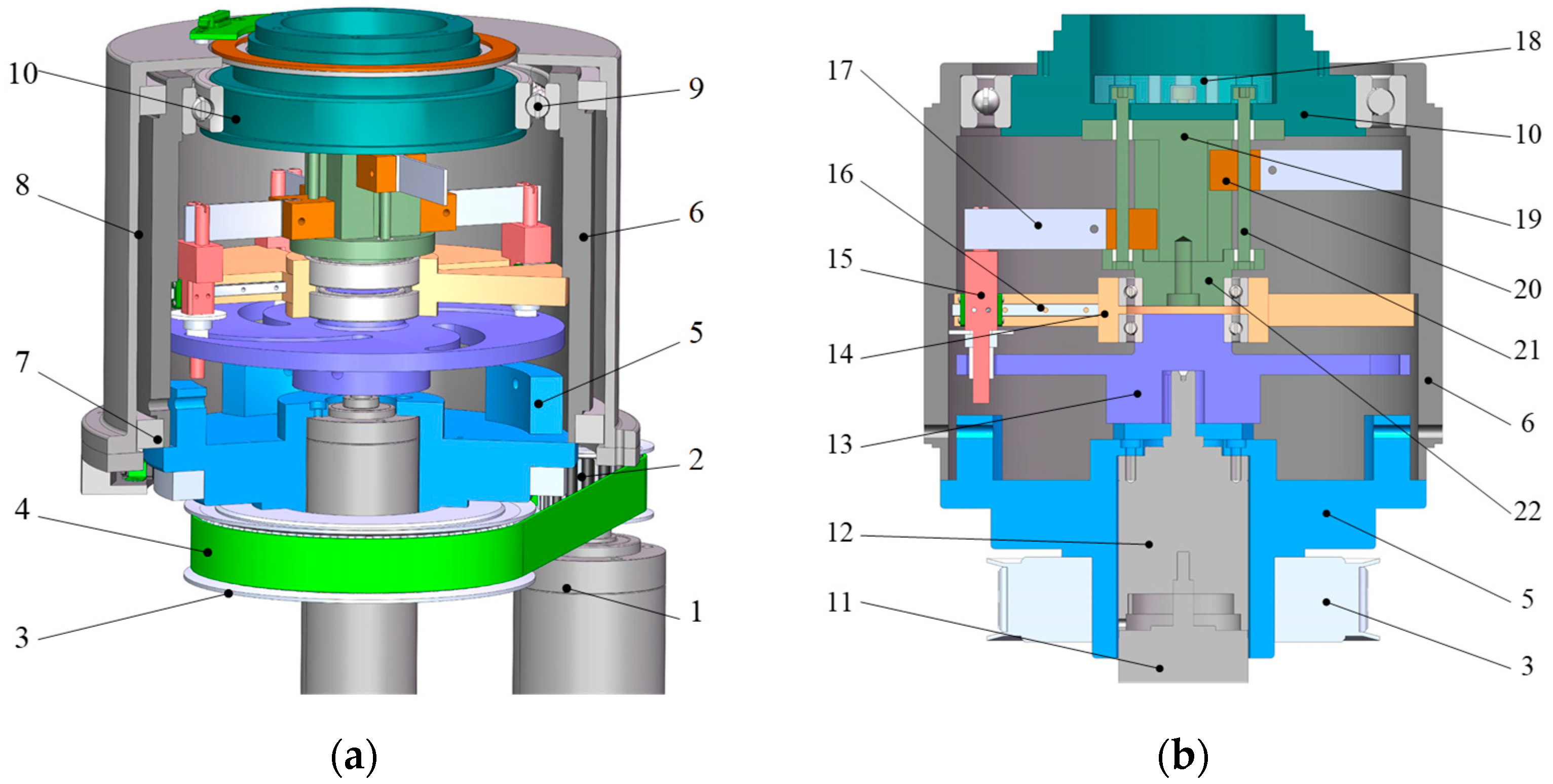
3. Overall Structural Design of VSJ

The structural design of the reconfigurable compliant robotic joint is shown in Figure 10. It includes a securing case, input section, variable stiffness module, and an output section. The input and output sections are connected in series through the variable stiffness module. The input section includes the main drive frame (part 6) and the drive disc (part 5). The two ends of this main drive frame are mounted inside the barrel-shaped securing case (part 8) via the use of bearings (part 7). The drive disc is fixed to the lower end of the main drive frame. The variable stiffness module and the main drive frame can be considered as one component. The output section is the output disc (part 10), which is mounted inside the main drive frame via a bearing (part 9). The drive disc and output disc are connected by a variable stiffness transmission section, which is located inside the main drive frame. The drive disc (part 5) is sleeved with a large timing pulley (part 3), which is connected to the small timing pulley (part 2) via a timing belt (part 4). The small timing pulley is coaxially connected to the drive motor (part 1).
As shown in Figure 11, the variable stiffness section includes a compliant stiffness adjustment device, positioned near the drive disc, and a stiffness/load reconfiguration device near the output disc. The transmission disc (part 14) with N evenly distributed radial slots is fixed in the middle of the main drive frame. The slider (part 15) with a columnar slide block at the lower end is arranged perpendicularly to the transmission disc, meaning it is able to slide radially along the slot. The stiffness regulation disc (part 13) with N arcuate slots in a gradually opening linear shape is installed at the lower part of the transmission disc. Sliding pairs are formed by inserting the slide blocks into the corresponding arcuate slots. The stiffness regulation disc is connected to the stiffness adjustment motor (part 11 and part 12) installed in the middle of the drive disc (part 5). The transmission disc, stiffness regulation disc, and motor located at the middle of the drive disc are coaxially connected.
Considering the frictional force between the slider and the linear slot of the transmission disc, corresponding miniature rails (part 16) are installed in the linear slots of the transmission disc, thus reducing the influence of frictional force on its movement, and avoiding jamming. During the operation of the stiffness adjustment module, the servo motor actuates the rotation of the adjustment disc. This instigates a radial displacement of the slider within the linear slot of the input frame. Consequently, the interaction point between the slider and the leaf spring changes, which modifies the effective working length of the leaf spring. Under load conditions, this results in the differential deflection of the leaf spring, thereby inducing a change in the joint’s stiffness parameter K.
As shown in Figure 12, the stiffness/load reconfiguration device includes a support column (Part 19), which extends from the center of the output disc (Part 10) towards the main drive frame, as well as a leaf spring reconfiguration mechanism, which is configured around the support column. The reconfiguration mechanism includes a lower end cover (Part 22) that matches the support column, a screw end cover (Part 18) which is used to restrict the radial movement of the screw, a screw (Part 21) parallel to the axial direction of the support column, and a leaf spring seat (Part 20) fitted onto the screw. The outer side of the leaf spring seat is fixed to the leaf spring end (Part 17), while there are matching sliders and slides between the inner side of the leaf spring seat and the support column. The free end of the leaf spring is clamped between the two column heads of the double fork body. In order to adjust the quantity of leaf springs engaged in the transmission process, the screw (Part 21) can be manually (or automatically, if necessary) individually rotated. This action induces the corresponding leaf spring seat to traverse along the axial direction of the VSJ, thereby facilitating the vertical displacement of the corresponding leaf spring. When L > h, the leaf spring completely disengages from the double fork body of the slider. At this point, the leaf spring does not participate in the stiffness adjustment. The adaptability of the VSJ to the current working condition is enhanced by the discrete adjustment of the stiffness range of the VSJ and its load capacity.
Under normal operation conditions, the input torque is transmitted from the drive motor to the output frame in the order shown in Figure 10a as follows: 1—drive motor → 2—timing belt drive → 3—drive disc → 4—main drive frame → 5—slider → 6—leaf spring → 7—output disc. At the initial stage of the joint’s operation, the compliance of the joint is achieved via the bending of the leaf spring under the action of the load. The bending of the leaf spring absorbs the energy fluctuations of the load, thus preventing sudden load changes from impacting the joint. Simultaneously, the joint driving process becomes more stable, which also serves as a form of protection for the robot joint. During the cyclic movement of the motion, the compliance of the joint has the potential to repeatedly utilize the energy stored in the spring deformation, which contributes to a more energy-efficient operation.
Moreover, in order to perceive external forces within a certain range and obtain feedback of key control variables, the sensing system of the proposed VSJ includes three encoders. An encoder ring is installed on the outer side of the drive end disk, which is used to measure the relative rotation between the drive end disk and the shell, while reader 1 is installed at the lower end of the shell. Another encoder is installed at the tail of the stiffness adjustment motor, which is used to measure the relative rotation angle between the stiffness adjustment disk and the transmission disk. This angle is used to calculate the effective length of the leaf spring during the stiffness adjustment process, based on the kinematic relationships. An encoder ring is installed on the circumferential surface of the output end disk, and reader 2 is set on the end face of the shell, which is then used to measure the relative rotation between the output end disk and the shell. Based on the difference between the data of the two readers and the calibrated mechanical zero point, the elastic deviation angle of the entire VSJ can be obtained. Combined with the established stiffness model (refer to Equation (9)), the magnitude of external forces or load forces can be perceived to a certain extent.
The design of the VSJ concerns future exoskeleton robot scenarios. By referring to the existing literature and combining the above simulation process attempts, the design parameters of the VSJ shown in Table 2 are finally obtained. The diameter, height (axial), and part material of the VSJ are limited at the beginning of the design, based on past experiences. After the design is completed, the final dimensions and estimated weight are obtained via measuring of the CAD model. The maximum elastic torque is obtained through the use on Equation (7) and simulation analysis (as shown in Figure 7). Under the assumption of small deformation, combined with empirical values and safety factors, the maximum deformation θ of the leaf spring can be limited at about 9°, and the deflection angle range φ of the joint can be solved using Equation (2). Similarly, the stiffness adjustment range can also be obtained via the use of Equation (9) and simulation analysis (as shown in Figure 3). Referring to Figure 1, when the slider approaches the fixed end of the leaf spring, K also tends towards infinity, thus obtaining a large stiffness adjustment bandwidth. Other parameters are preset values and can be flexibly modified during the design process for different application scenarios.
In order to compare and analyze the advantages of the proposed VSJ, several similar VSAs are selected for comparison, as shown in Table 3. The stiffness adjustment bandwidth of the VSJ is relatively large when compared to vsaUT-II [20], REGT-VSA [23] and CLSM-VSA [29]. According to the step response simulation analysis, the stiffness regulation time of the VSJ is about 0.34 s, which is relatively fast. This is mainly due to the simplicity of the stiffness adjustment mechanism, which adjusts the stiffness only via rotary motion, thus avoiding the response delay caused by the ball screw or rocker linkage mechanism when used to convert rotary motion into linear motion. It is worth noting that the proposed reconfigurable performance of the VSJ is the most competitive. With the help of this reconfigurable mechanism, the stiffness adjustment range and nominal elastic torque of the VSJ can be easily expanded for a specific requirement without requiring any disassembly and re-assembly of the actuators. Compared with RVSA [31] and CLSM-VSA [29], this design advantage avoids the tedious work of recalibration and debugging required after disassembling the actuator, and has high practical value. However, as it is currently in the conceptual design stage, the weight of the VSJ is only measured using CAD models, resulting in a relatively large theoretical weight. However, this can be reduced through the use of lightweight design methods, such as finite element simulations and structural topology optimization, before the prototype is built, if necessary.

4. Dynamics Modeling and Simulation Analysis

This section is divided by subheadings. It should provide a concise and precise description of the experimental results, their interpretation, as well as the experimental conclusions that can be drawn.

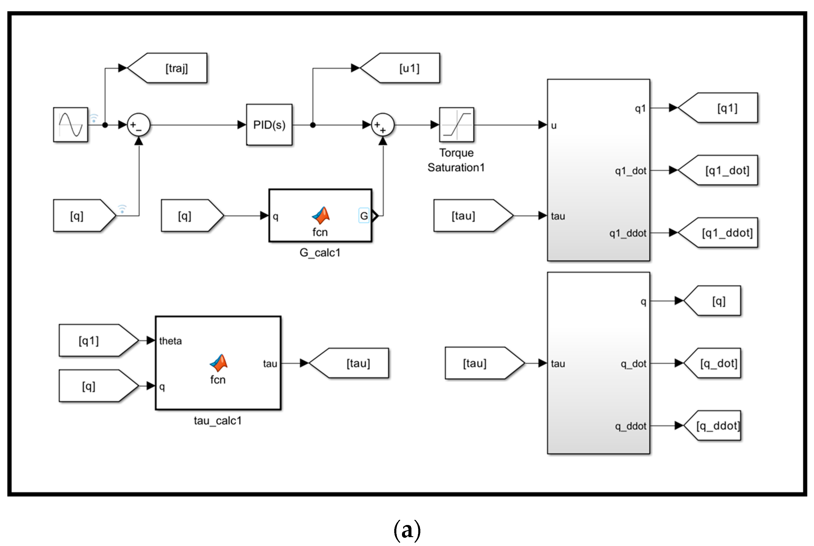
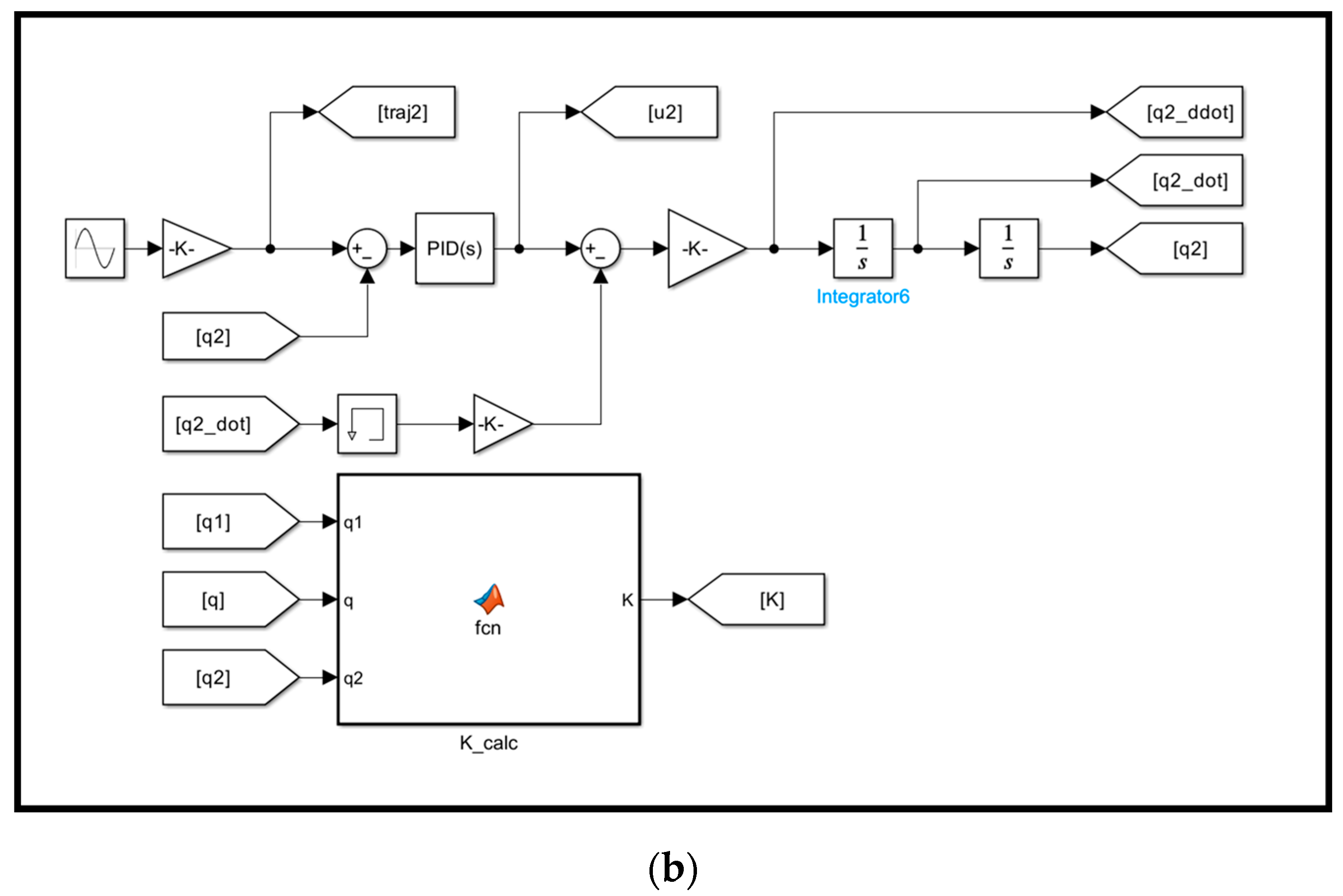
4.1. Dynamic Modeling

The dynamic model of the reconfigurable VSJ is shown in Figure 13. It contains two links: the position driving chain and the stiffness adjustment chain.
The dynamic equations of the joint are defined as follows:
J q ¨ + D q ˙ + τ e x t = K s q 1 q J 1 q ¨ 1 + D 1 q ˙ 1 + K s q 1 q = u 1 J 2 q ¨ 2 + D 2 q ˙ 2 + τ r = u 2
where J , D , and q represent the inertia, damping, and position of the output shaft, respectively. J 1 , J 2 , D 1 , D 2 , q 1 , q 2 , u 1 , and u 2 represent the inertia, damping, position, and control torque of the input shaft and the VSM, respectively. τ r and τ e x t represent the stiffness adjustment resistant torque and load torque, respectively.
Based on Equation (17), the following relations are derived:
q ¨ = K s J q 1 q D J q ˙ τ e x t J q ¨ 1 = u 1 J 1 D 1 J 1 q ˙ 1 K s J 1 q 1 q q ¨ 2 = u 2 J 2 D 2 J 2 q ˙ 2 τ J 2
Based on Equation (18), the dynamic model of the VSJ is built using Matlab/Simulink (R2019a), as shown in Figure 14.

4.2. Controller Design

In order to verify the basic motion performance of the proposed VSJ, a PID controller was designed for the main drive chain and the VSM drive chain, as shown in Figure 15. The position information of the output end disk and the input end disk is provided by sensors, which are installed at the corresponding positions, and is used to calculate the elastic deviation angle of the entire VSJ. The angle information of the stiffness adjustment disk is provided by the sensor at the end of the stiffness adjustment motor. Based on the stiffness model established using Equation (9), the effective length of the leaf spring can be calculated. Furthermore, based on Equation (16), the rotational position information of the stiffness adjustment transmission chain can be determined.

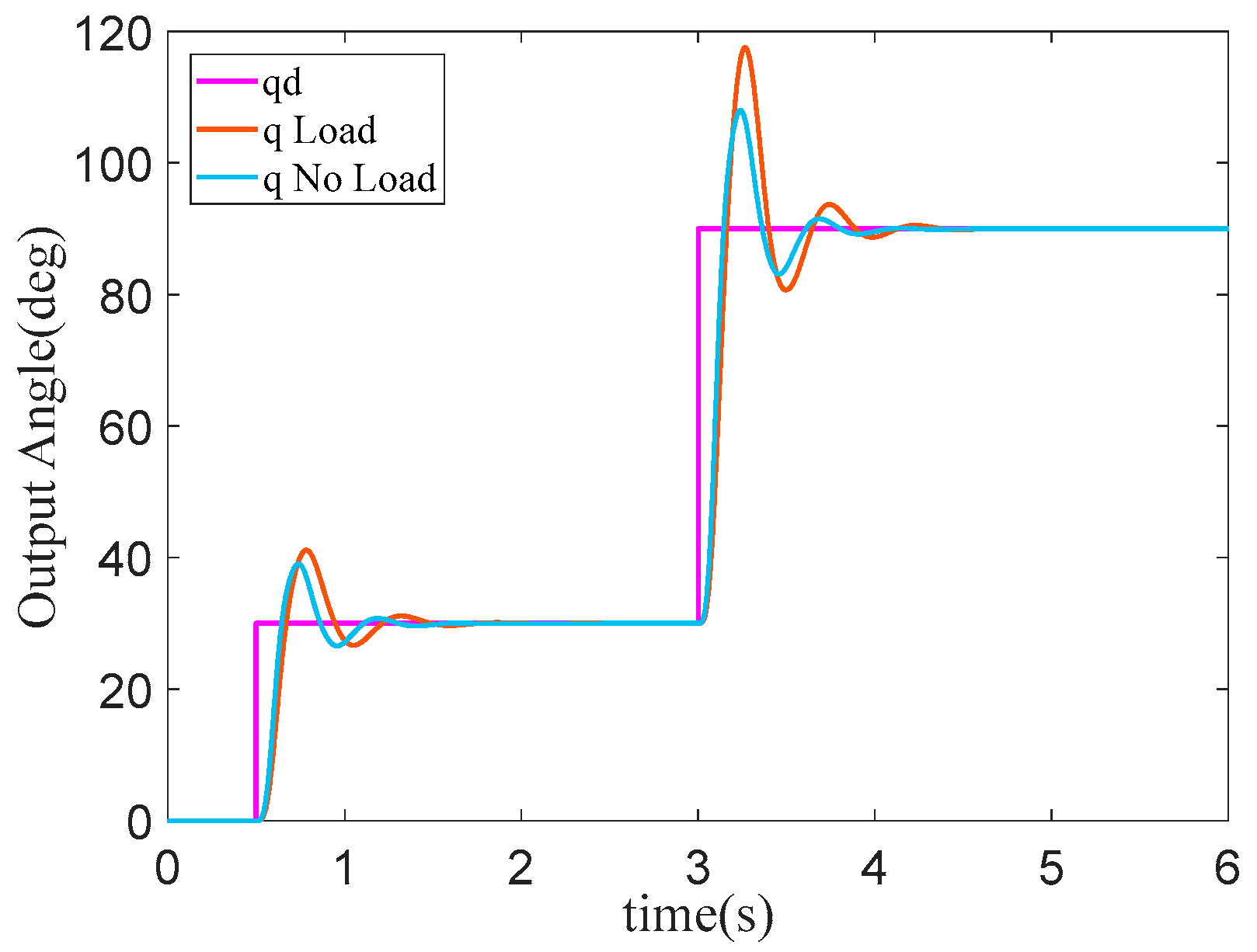
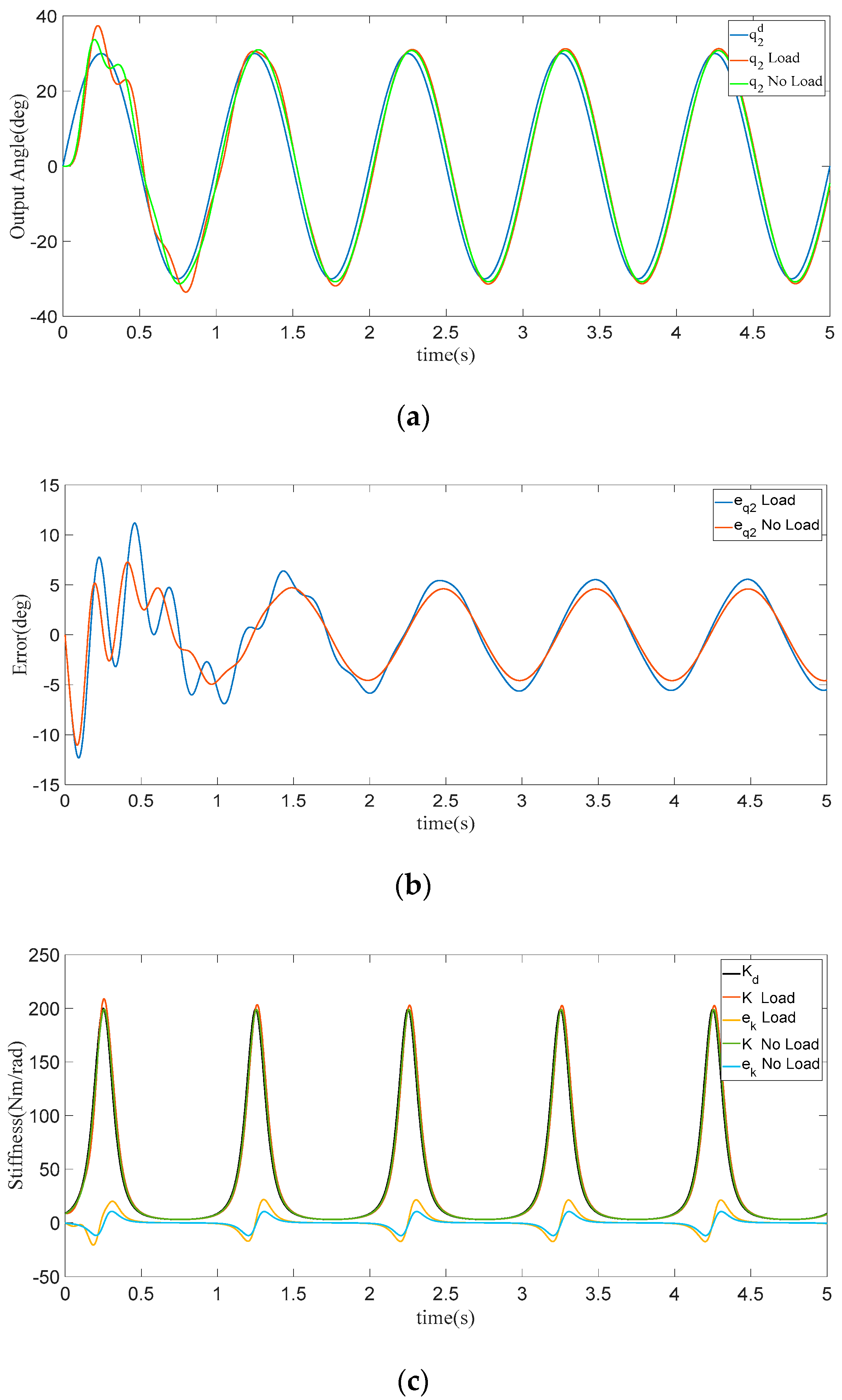
4.3. Results of Dynamic Modeling

In order to examine the stiffness response performance and position tracking performance of the designed VSJ, step and sine tracking signals were designed to carry out motion simulation, based on the above controller (Figure 15). The step response of the output position of the main drive module, at the stiffness level of 200 Nm/rad, is illustrated in Figure 16. In the step response, the no-load tracking response is relatively fast, while, as the load increases, the settling time is significantly longer, having been extended by 0.25 s, whereas the overshoot also increases by 5%. In the large stroke step response, the settling time of the main drive module output is slightly increased, extended by 0.16 s, and the overshoot is also increased by 15%. As the load increases, the overshoot and settling time also increase significantly, indicating that more advanced control algorithms need to be investigated, allowing the VSJ to cope with load changes in such working conditions.
The response curve of the lever position in the VSJ is illustrated in Figure 17. Under both no-load and load conditions, the response speed of the VSJ remains almost the same. In the large-stroke step response, as the load increases, the overshoot of the lever position increases slightly, meaning it can be ignored, indicating that its elastic deflection angle has almost no effect on the lever position. This further indicates that the coupling between the elastic deflection and actuator stiffness is slight, which is consistent with the above simulation results shown in Figure 3.
The synchronous tracking performance of the output frame under a sine signal with a frequency of 1 Hz and an amplitude of 30° is demonstrated in Figure 18, where the stiffness of the VSJ is fixed at 200 Nm/rad. The output position tracking performance and tracking error are shown in Figure 18a,b, respectively. The maximum tracking error under load and no-load conditions occurs in the initial motion stage, which is about 13° and 11°, respectively; this is largely due to the serial elastic stage in the VSJ. After the system gradually stabilizes, the tracking error under no-load and load conditions converges to 6° and 4°, respectively. Clearly, the load has a certain deterioration effect on the tracking performance. In addition, in order to verify the anti-interference performance of the synchronous variable stiffness under the no-load condition, the VSM also tracks a sine signal with a frequency of 1 Hz and an amplitude of 200 Nm/rad, as shown in Figure 18c. The maximum tracking error is about 10 Nm/rad. Under the load condition, the maximum tracking error is about 16 Nm/rad. The results emphasize that the load has a very small impact on the joint stiffness.

5. Conclusions

This paper proposed a novel VSJ, inspired by the principle of the effective beam length of a leaf spring. The wide stiffness range and fast adjustment speed from a minimum level to near infinite was achieved through driving the specially designed disc via rotation only. With the help of the reconfiguration mechanism, the stiffness adjustment range and nominal elastic torque or load capacity of the VSJ can be easily expanded for a specific requirement without the disassembling and re-assembling of the actuators. Mathematical models of the VSJ were derived and verified through adequate simulation analysis. The simulation results proved the fast regulation speed and good tracking performance of the VSJ using a simple controller, which validated the simplicity of the design. One limitation of the proposed design is that the maximum deflection angle is not large enough, which is not conducive to reverse driving in human–robot interactions. However, this can be expanded in future studies via the structural optimization of joints and springs. The weight of the VSJ should also be further reduced via reasonable structural optimization before the upcoming prototype manufacturing. Following this, the physical prototype of the VSJ is expected to be applied to a flexible robot with multiple degrees of freedom. Consequently, advanced control algorithms should be designed for the VSJ in the expected human–robot interaction applications.

Author Contributions

Conceptualization, C.W. and Y.X.; methodology, X.W.; software, Y.G.; validation, Y.G., Y.X. and L.W.; formal analysis, Y.G.; investigation, C.W.; resources, Y.G.; data curation, Y.G.; writing—original draft preparation, Y.G.; writing—review and editing, Y.X.; visualization, Y.G.; supervision, C.W.; project administration, C.W.; funding acquisition, Y.X. All authors have read and agreed to the published version of the manuscript.

Funding

This research was supported by the Open Project of Henan Key Laboratory of Intelligent Manufacturing of Mechanical Equipment, Zhengzhou University of Light Industry (No. IM202312), the Doctoral Research Fund of Zhengzhou University of Light Industry (No. 2022BSJJZK02), the Program for Science & Technology Innovation Talents in Universities of Henan Province (Grant No. 22HASTIT023), and the National Natural Science Foundation of China (Grant No. 52075500).

Institutional Review Board Statement

Not applicable.

Informed Consent Statement

Not applicable.

Data Availability Statement

The data used to support the findings of this study are available from the corresponding author upon request. The data are not publicly available due to privacy.

Conflicts of Interest

The authors declare no conflicts of interest.

References

  1. Zacharaki, A.; Kostavelis, I.; Gasteratos, A.; Dokas, I. Safety bounds in human robot interaction: A survey. Saf. Sci. 2020, 127, 104667. [Google Scholar] [CrossRef]
  2. Sun, L.; Li, M.; Wang, M.; Yin, W.; Sun, N.; Liu, J. Continuous finite-time output torque control approach for series elastic actuator. Mech. Syst. Signal Proc. 2020, 139, 105853. [Google Scholar] [CrossRef]
  3. Zhang, M.; Ma, P.; Sun, F.; Sun, X.; Xu, F.; Jin, J.; Fang, L. Dynamic Modeling and Control of Antagonistic Variable Stiffness Joint Actuator. Actuators 2021, 10, 116. [Google Scholar] [CrossRef]
  4. Gao, X.; Li, X.; Zhao, C.; Hao, L.; Xiang, C. Variable stiffness structural design of a dual-segment continuum manipulator with independent stiffness and angular position. Robot. Comput. Integr. Manuf. 2021, 67, 102000. [Google Scholar] [CrossRef]
  5. Wolf, S.; Grioli, G.; Eiberger, O.; Friedl, W.; Grebenstein, M.; Hoeppner, H.; Burdet, E.; Caldwell, D.G.; Carloni, R.; Catalano, M.G.; et al. Variable Stiffness Actuators: Review on Design and Components. IEEE/ASME Trans. Mechatron. 2016, 21, 2418–2430. [Google Scholar] [CrossRef]
  6. Harder, M.; Keppler, M.; Meng, X.; Ott, C.; Hoeppner, H.; Dietrich, A. Simultaneous Motion Tracking and Joint Stiffness Control of Bidirectional Antagonistic Variable-Stiffness Actuators. IEEE Robot. Autom. Lett. 2022, 7, 6614–6621. [Google Scholar] [CrossRef]
  7. Xiong, X.; Sun, X.; Chen, W.; Zhi, Y.; Fang, X. Design of a Variable Stiffness Actuator Based on Variable Radius Mechanisms. In Proceedings of the 2022 IEEE/ASME International Conference on Advanced Intelligent Mechatronics (AIM), Sapporo, Japan, 11–15 July 2022. [Google Scholar]
  8. Bilancia, P.; Berselli, G.; Palli, G. Virtual and physical prototyping of a beam-based variable stiffness actuator for safe human-machine interaction. Robot. Comput. Integr. Manuf. 2020, 65, 101886. [Google Scholar] [CrossRef]
  9. Liu, Y.; Liu, X.; Yuan, Z.; Liu, J. Design and analysis of spring parallel variable stiffness actuator based on antagonistic principle. Mech. Mach. Theory 2019, 140, 44–58. [Google Scholar] [CrossRef]
  10. Grioli, G.; Wolf, S.; Garabini, M.; Catalano, M.; Burdet, E.; Caldwell, D.; Carloni, R.; Friedl, W.; Grebenstein, M.; Laffranchi, M.; et al. Variable stiffness actuators: The user’s point of view. Int. J. Robot. Res. 2015, 34, 727–743. [Google Scholar] [CrossRef]
  11. Bacek, T.; Moltedo, M.; Geeroms, J.; Vanderborght, B.; Rodriguez-Guerrero, C.; Lefeber, D. Varying mechanical compliance benefits energy efficiency of a knee joint actuator. Mechatronics 2020, 66, 102318. [Google Scholar] [CrossRef]
  12. Wolf, S.; Feenders, J.-E. Modeling and benchmarking energy efficiency of Variable Stiffness Actuators on the example of the DLR FSJ. In Proceedings of the 2016 IEEE/RSJ International Conference on Intelligent Robots and Systems (IROS), Daejeon, Republic of Korea, 9–14 October 2016. [Google Scholar]
  13. Torrealba, R.R.; Udelman, S.B.; Fonseca-Rojas, E.D. Design of variable impedance actuator for knee joint of a portable human gait rehabilitation exoskeleton. Mech. Mach. Theory 2017, 116, 248–261. [Google Scholar] [CrossRef]
  14. Wang, C.; Sheng, B.; Li, Z.; Sivan, M.; Zhang, Z.-Q.; Li, G.-Q.; Xie, S.Q. A Lightweight Series Elastic Actuator with Variable Stiffness: Design, Modeling, and Evaluation. IEEE/ASME Trans. Mechatron. 2023, 28, 3110–3119. [Google Scholar] [CrossRef]
  15. Zhu, Y.; Wu, Q.; Chen, B.; Xu, D.; Shao, Z. Design and evaluation of a novel torque-controllable variable stiffness actuator with reconfigurability. IEEE/ASME Trans. Mechatron. 2021, 27, 292–303. [Google Scholar] [CrossRef]
  16. Jiang, N.; Sun, S.; Ouyang, Y.; Xu, M.; Li, W.; Zhang, S. A highly adaptive magnetorheological fluid robotic leg for efficient terrestrial locomotion. Smart Mater. Struct. 2016, 25, 095019. [Google Scholar] [CrossRef]
  17. Van Ham, R.; Sugar, T.G.; Vanderborght, B.; Hollander, K.W.; Lefeber, D. Compliant actuator designs. IEEE Robot. Autom. Mag. 2009, 16, 81–94. [Google Scholar]
  18. Jafari, A.; Tsagarakis, N.G.; Caldwell, D.G. A novel intrinsically energy efficient actuator with adjustable stiffness (AwAS). IEEE/ASME Trans. Mechatron. 2011, 18, 355–365. [Google Scholar] [CrossRef]
  19. Liu, Y.; Cui, S.; Sun, Y. Mechanical design and analysis of a novel variable stiffness actuator with symmetrical pivot adjustment. Front. Mech. Eng. 2021, 16, 711–725. [Google Scholar] [CrossRef]
  20. Groothuis, S.S.; Rusticelli, G.; Zucchelli, A.; Stramigioli, S.; Carloni, R. The variable stiffness actuator vsaUT-II: Mechanical design, modeling, and identification. IEEE/ASME Trans. Mechatron. 2013, 19, 589–597. [Google Scholar] [CrossRef]
  21. Sarani, B.; Ahmadi, H. Mechanical design and control of a novel variable impedance actuator (VIA) for knee joint of a rehabilitation exoskeleton. J. Braz. Soc. Mech. Sci. Eng. 2022, 44, 81. [Google Scholar] [CrossRef]
  22. Wang, W.; Fu, X.; Li, Y.; Yun, C. Design and implementation of a variable stiffness actuator based on flexible gear rack mechanism. Robotica 2018, 36, 448–462. [Google Scholar] [CrossRef]
  23. Li, Z.; Xu, P.; Huang, H.; Ning, Y.; Li, B. A novel variable stiffness actuator based on a rocker-linked epicyclic gear train. Mech. Mach. Theory 2022, 177, 105035. [Google Scholar] [CrossRef]
  24. Liu, Z.; Jin, H.; Zhang, H.; Liu, Y.; Zhao, J. A Variable Stiffness Actuator Based on Second-order Lever Mechanism and Its Manipulator Integration. In Proceedings of the 2021 IEEE International Conference on Robotics and Automation (ICRA), Xi’an, China, 30 May–5 June 2021. [Google Scholar]
  25. Sun, J.; Guo, Z.; Sun, D.; He, S.; Xiao, X. Design, modeling and control of a novel compact, energy-efficient, and rotational serial variable stiffness actuator (SVSA-II). Mech. Mach. Theory 2018, 130, 123–136. [Google Scholar] [CrossRef]
  26. Choi, J.; Hong, S.; Lee, W.; Kang, S.; Kim, M. A robot joint with variable stiffness using leaf springs. IEEE Trans. Robot. 2011, 27, 229–238. [Google Scholar] [CrossRef]
  27. Liu, L.; Misgeld, B.J.E.; Pomprapa, A.; Leonhardt, S. A Testable Robust Stability Framework for the Variable Impedance Control of 1-DOF Exoskeleton with Variable Stiffness Actuator. IEEE Trans. Control Syst. Technol. 2021, 29, 2728–2737. [Google Scholar] [CrossRef]
  28. Wang, W.; Zhao, Y.; Li, Y. Design and dynamic modeling of variable stiffness joint actuator based on archimedes spiral. IEEE Access 2018, 6, 43798–43807. [Google Scholar] [CrossRef]
  29. Shao, Y.; Shi, D.; Zhang, W.; Ding, X. Design and Evaluation of Variable Stiffness Actuators with Predefined Stiffness Profiles. IEEE Trans. Autom. Sci. Eng. 2023, 1–13. [Google Scholar] [CrossRef]
  30. Wu, J.; Wang, Z.; Chen, W.; Wang, Y.; Liu, Y.-H. Design and validation of a novel leaf spring-based variable stiffness joint with reconfigurability. IEEE/ASME Trans. Mechatron. 2020, 25, 2045–2053. [Google Scholar] [CrossRef]
  31. Xu, Y.; Guo, K.; Li, J.; Li, Y. A novel rotational actuator with variable stiffness using S-shaped springs. IEEE/ASME Trans. Mechatron. 2020, 26, 2249–2260. [Google Scholar] [CrossRef]
  32. Xiong, J.; Sun, Y.; Zheng, J.; Dong, D.; Bai, L. Design and experiment of a SMA-based continuous-stiffness-adjustment torsional elastic component for variable stiffness actuators. Smart Mater. Struct. 2021, 30, 105021. [Google Scholar] [CrossRef]
  33. Ahmadi, A.; Asgari, M. Novel bio-inspired variable stiffness soft actuator via fiber-reinforced dielectric elastomer, inspired by Octopus bimaculoides. Intell. Serv. Robot. 2021, 14, 691–705. [Google Scholar] [CrossRef]
  34. Christie, M.; Sun, S.; Deng, L.; Du, H.; Zhang, S.; Li, W. Real-time adaptive leg-stiffness for roll compensation via magnetorheological control in a legged robot. Smart Mater. Struct. 2022, 31, 045003. [Google Scholar] [CrossRef]
  35. Xu, Y.; Guo, K.; Sun, J.; Li, J. Design and analysis of a linear digital variable stiffness actuator. IEEE Access 2021, 9, 13992–14004. [Google Scholar] [CrossRef]
  36. Li, W.-B.; Zhang, W.-M.; Zou, H.-X.; Peng, Z.-K.; Meng, G. Bioinspired variable stiffness dielectric elastomer actuators with large and tunable load capacity. Soft Robot. 2019, 6, 631–643. [Google Scholar] [CrossRef]
  37. Zhang, L.; Wang, W.; Shi, Y.; Chu, Y.; Ming, X. A new variable stiffness actuator and its control method. Ind. Rob. 2019, 46, 553–560. [Google Scholar] [CrossRef]
  38. Xu, Y.; Guo, K.; Sun, J.; Li, J. Design, modeling and control of a reconfigurable variable stiffness actuator. Mech. Syst. Signal Proc. 2021, 160, 107883. [Google Scholar] [CrossRef]
  39. Liu, H.; Zhu, D.; Xiao, J. Conceptual design and parameter optimization of a variable stiffness mechanism for producing constant output forces. Mech. Mach. Theory 2020, 154, 104033. [Google Scholar] [CrossRef]
Figure 1. Schematic diagram of the effective length adjustment mechanism for the leaf spring.
Applsci 14 02685 g001
Figure 3. Theoretical stiffness characteristics.
Applsci 14 02685 g003
Figure 4. Relationship between the joint stiffness and elastic deflection angle.
Applsci 14 02685 g004
Figure 5. Relationship between the effective length of the leaf spring and the rotation angle of the stiffness-varying disk.
Applsci 14 02685 g005
Figure 6. Relationship between joint stiffness and the effective length of the leaf spring.
Applsci 14 02685 g006
Figure 7. Theoretical elastic torque characteristics.
Applsci 14 02685 g007
Figure 8. Theoretical elastic potential energy characteristics.
Applsci 14 02685 g008
Figure 9. Variable stiffness damping torque characteristics.
Applsci 14 02685 g009
Figure 10. CAD model of the joint. (a) Partial sectional view. (b) Half sectional view of main drive frame: 1—Drive motor; 2—Small timing pulley; 3—Large timing pulley; 4—Timing belt; 5—Drive disc; 6—Main drive frame; 7—Bearing; 8—Securing case; 9—Bearing; 10—Output disc; 11—Stiffness adjustment motor; 12—Reducer; 13—Stiffness regulation disc; 14—Transmission disc; 15—Slider; 16—Micro slide rail; 17—Leaf spring; 18—Screw end cap; 19—Support column; 20—Leaf spring seat; 21—Screw; 22—Lower end cover.
Applsci 14 02685 g010
Figure 11. CAD model of the continuous variable stiffness mechanism: 13—adjustment disc; 14—transmission disc; 15—slider; 16—miniature slide rail.
Applsci 14 02685 g011
Figure 12. CAD model of stiffness/load reconfiguration mechanism: 15—Slider; 17—Leaf spring; 18—Screw end cover; 19—Support column; 20—Leaf spring seat; 21—Screw; 22—Lower end cover.
Applsci 14 02685 g012
Figure 13. Dynamic model of the VSJ.
Applsci 14 02685 g013
Figure 14. Simulink model of the VSJ: (a) main drive module; (b) stiffness adjustment module.
Applsci 14 02685 g014aApplsci 14 02685 g014b
Figure 15. PID controller block diagram.
Applsci 14 02685 g015
Figure 16. Step response of the main drive module output position.
Applsci 14 02685 g016
Figure 17. Step response of the lever position.
Applsci 14 02685 g017
Figure 18. Trajectory tracking performance: (a) Output position; (b) Position tracking error; (c) Stiffness tracking results.
Applsci 14 02685 g018
Table 2. Parameters of the VSJ and the leaf spring for simulation.
ParametersValueUnit
Diameter140mm
Height114mm
Weight4kg
Max. elastic torque with N = 114.6Nm
Stiffness adjustment rangeN × (9-inf.)Nm/rad
Output rotation range0–360°
Deflection angle range±3.03°
The leaf spring number N1/
The leaf spring width b25mm
The leaf spring thickness h1mm
Young’s modulus of the spring material E206GPa
The distance of O C ¯   r 1 54mm
The distance of O A ¯   r 2 25mm
The angle between O C ¯ and O A ¯   α 1 47°
Table 3. Comparisons of the specifications of the variable stiffness joint.
ItemsProposed
VSJ
vsaUT-II [20]REGT-VSA [23]RVSA
[31]
CLSM-VSA [29]
Regulation principlebeam
length
pivot of leverpivot of leverbeam lengthsection moment of inertia
Stiffness (Nm/rad)N × (9-inf.)0.7–94820–236220-inf.50–946
Range of motion (°)±360±28.6±180±360±180
Regulation Time (s)0.340.90.50.090.49
Nominal torque (Nm)N × 14.615221121
Size (mm)Φ140 × 114/Φ128 × 257Φ130 × 122Φ80 × 155
Weight (kg)42.54.52.081.78
Stiffness adjustment mechanismonly rotating the discplanetary gear trainrocker linkageonly rotating springball screw
Reconfigurable/
without disassembly
yesnonoyes/
disassembly.
yes/
disassembly.
Disclaimer/Publisher’s Note: The statements, opinions and data contained in all publications are solely those of the individual author(s) and contributor(s) and not of MDPI and/or the editor(s). MDPI and/or the editor(s) disclaim responsibility for any injury to people or property resulting from any ideas, methods, instructions or products referred to in the content.

