Abstract
A control method for a cable-driven robot in a teleoperation system is proposed using the hardware-in-the-loop (HIL) simulation technique. The main components of the teleoperated robotic system are a haptic device, also called a delta robot, and a cable-driven hyper-redundant (CDHR) robot. The CDHR manipulator has higher flexibility and multiple degrees of freedom (DOF), and, therefore, its inverse kinematics are complex. For this reason, the Jacobian method is used in place of the conventional method to calculate the inverse kinematics. Moreover, the two robots constituting the telerobotic system are different in terms of their mechanical structures and workspaces. Therefore, the position mapping method is applied to ensure that the two workspaces are utilized together. However, a singularity area appears when the mapping parameter is adjusted to expand the workspace. Therefore, a haptic algorithm is proposed to prevent the robot from moving into the singularity region and generate force feedback at the end-effector of the haptic device to warn the operator. Because experimental verification of this control strategy is difficult, the HIL technique is used for demonstration in this study to ensure stability and safety before implementation of the method at the experiment scale. The CDHR robot is designed using SolidWorks 2021. Then, the Simscape model is used to simulate the telerobotic system. In addition, the protocol between the haptic device and the laptop is programmed using C/C++ language to facilitate communication with the CDHR robot in MATLAB Simulink 2022a. A few trials are conducted to evaluate and demonstrate the effectiveness of the proposed method.
1. Introduction
Teleoperation systems help humans to remotely implement tasks in hazardous environments, such as ocean exploration, space exploration, and surgery [1,2,3]. A simple teleoperation system comprises a master at the local site and a slave at the remote site. Because of the different structures of the master and slave nodes, controlling the entire teleoperation system is challenging. The most common problems include time delay, information loss, and singularity [4,5,6,7,8,9,10]. It is difficult to conduct experiments in practice using algorithms because any implementation must be safe and stable during operation. Additionally, in industrial environments, slave robots are used as redundant robots to increase operational flexibility, rather than using a single robot to repeat a given task. In this manner, difficult tasks can be performed relatively easily, and collisions in the working environment can be avoided. However, the kinematics mathematics of the slave robot become complicated when it has multiple degrees of freedom [11,12]. Therefore, the hardware-in-the-loop (HIL) method, which simulates a part of an entire system, has been studied and applied for simulating the behavior of various components of teleoperation systems based on the specification model.
The computer executes the digital models whose parameters are identified from the physical models [13]. To compensate the velocity divergence on the motion simulator due to the time delay, a response error real-time feedback based force compensation approach [14] was proposed. In this study, a HIL docking simulator was used to describe the motion and dynamics of the system. In the field of electrical drive control, HIL simulation has been used to improve convenience and flexibility in an application involving space robots [15,16], as well as for implementing tasks such as repair, upgrade, transportation, and recuse [14,15]. Visteon Corp. applied HIL simulation to improve quality and reduce the cost of its testing systems [17]. HIL simulation systems can bypass the risks of models to eliminate unnecessary factors that increase the simulation cost and time, as well as the dangers associated with electronic systems [18,19]. In the orthopedics field, the process of testing total hip dislocation under physiological conditions has been conducted using HIL simulation to improve the accuracy of diagnosis [20]. Specifications about the battery capacity, and balance circuits of the battery management system were tested carefully to ensure its effectiveness. The results of a comparison between the real battery and the HIL simulator are show in [18]. In universities, research on HIL simulation is encouraged for building low-cost hardware, supporting studies conducted by students working on automation systems [21], and supporting related industrial activities [22]. When a teleoperation system is fully simulated or set up in an experimental environment, it is difficult to deploy algorithms or train system operators. In such cases, HIL simulation is used to deploy the target process in Unity 3D to make sure that the environment feels realistic to the operator [13,23].
In this paper, a control method for a cable-driven hyper-redundant (CDHR) robot used in a teleoperation system is proposed using the HIL method. To guarantee the safety and stability of the telerobotic system, the algorithms are implemented in an HIL simulation, in combination with the physical models, using MATLAB Simulink 2019a software. The method comprises the Jacobian method, position mapping, and the haptic algorithm. Because the inverse kinematics of the redundant robot cannot be calculated using the common method, the Jacobian method is used to calculate it. In addition, the size and structure of both robots in the teleoperation system are different, and, therefore, position mapping is used to unify their workspaces for controlling the teleoperation system. However, the singularity region is located outside the remote site, resulting in loss of control over the CDHR robot when workspace mapping is extended. Therefore, the haptic algorithm is applied to generate a virtual force that acts on the palm of the CDHR robot to prevent the robot from moving outside the permitted workspace, which guarantees system stability and safety. The process is implemented in the HIL simulation system because the factors of safety and stability must be ensured before its application to the full experimental model.
The remainder of this paper is organized as follows: A description of the HIL simulation system is presented in Section 2. The proposed method is discussed in Section 3. The simulation and experiments are described in Section 4 and Section 5, respectively. Finally, a few conclusions are presented in Section 6.
2. Description of HIL Simulation System
2.1. HIL Simulation System
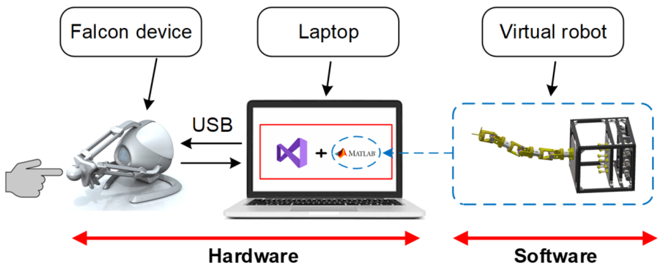
An overview of the HIL simulation system, including the hardware and software systems, is presented in Figure 1. The haptic device is called the Novint Falcon (Novint Technologies, Albuquerque, NM, USA) device or the delta robot, and it is used to generate the desired trajectory when the operator operates the system. To facilitate communication between the haptic device and the virtual robot, a program authored in C/C++ in the Visual Studio 2019 software development environment is used. In addition, the robot model is simulated in the MATLAB/Simulink 2022a software environment after receiving data from the haptic device.
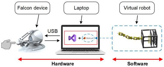
Figure 1.
Overview of HIL simulation system.
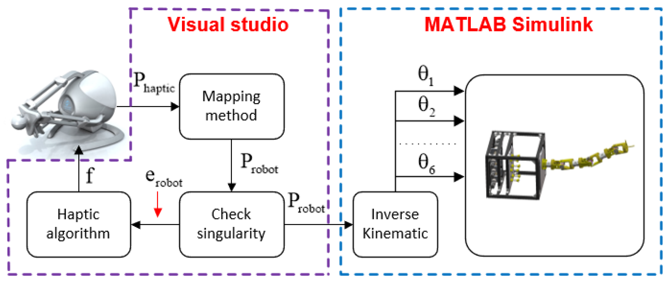
The process flow of the entire system is depicted in Figure 2. The operator interacts with the haptic device at the end-effector. Simultaneously, the sensor measures the position of each joint and interpolates it to the position of the haptic device. Then, the position is calculated using the mapping method to utilize the workspace between the Novint Falcon and the cable robot. Moreover, this point can be checked to eliminate singularity before sending it to the robot. If singularity exists, the haptic mode is implemented to generate a force based on the error in robot position in Visual Studio. Then, the inverse kinematics of the cable robot is resolved using the Jacobian method to determine the angle of each joint; these determined angle values are used in the Simscape model.
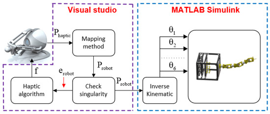
Figure 2.
Block diagram of HIL simulation.
2.2. Mechanism Design of CDHR robot
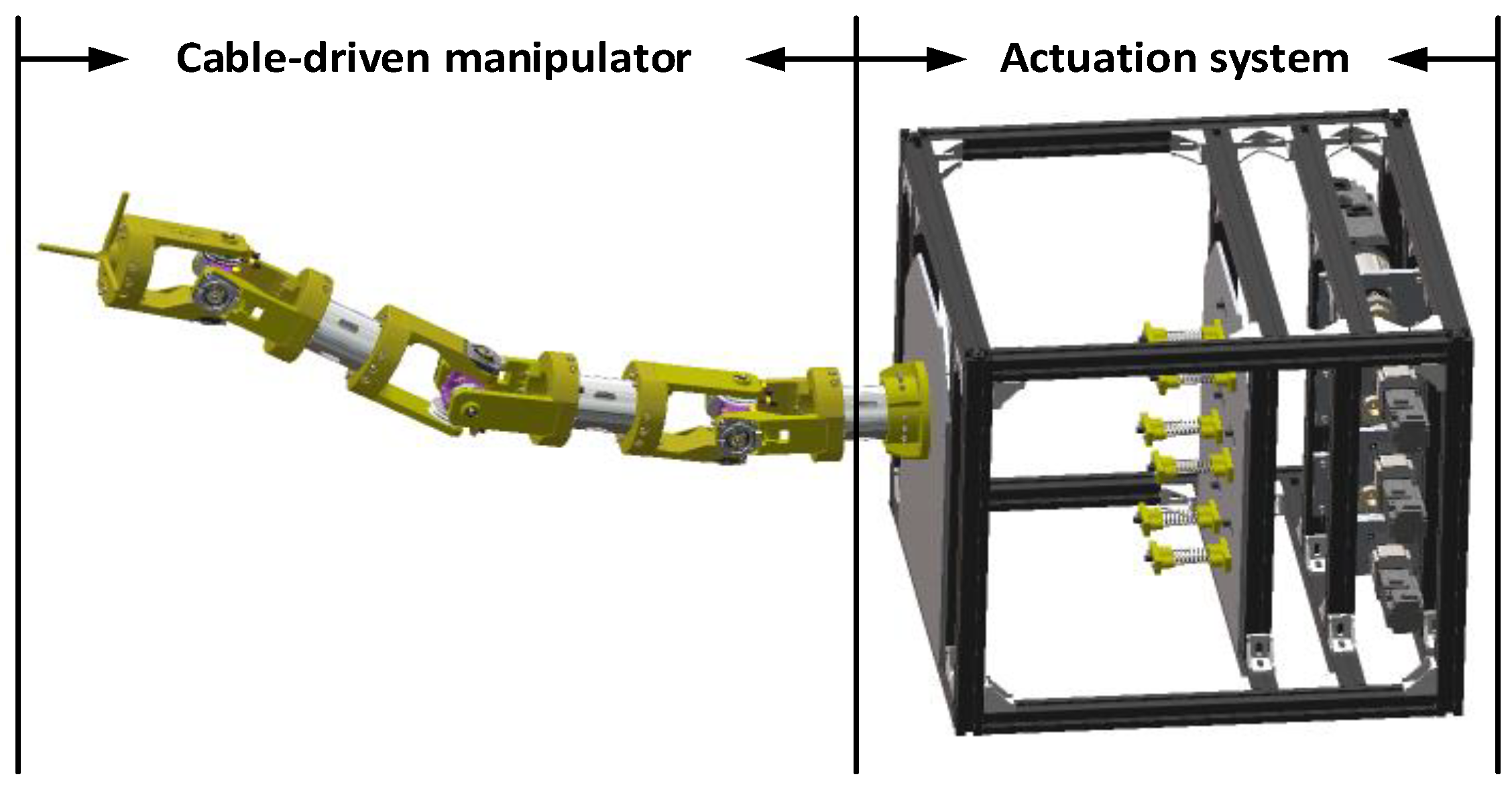
The 3D model of the CDHR robot comprises an actuation system and a cable-driven manipulator, as depicted in Figure 3. The cable-driven manipulator contains four sections that are serially connected to adjacent sections through universal joints, as shown in Figure 4a. To clearly illustrate the structure of the cable-driven manipulator, the detailed structures of each of the sections are shown in Figure 4b. Each section consists of a link, two disks, an intestinal lumen, two arms, and two rotating joints whose rotation axes are perpendicular to each other. One disk and two arms connect a universal joint to the link. Every universal joint includes two pulley joints and an intestinal lumen to create a form for laying electric wires in them. To achieve universal joint motion, cables are used to drive the two rotation joints.
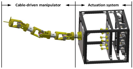
Figure 3.
General structure of CDHR robot, which consists of an actuation system and a cable-driven manipulator.
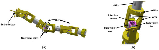
Figure 4.
Model of CDHR robot: (a) cable-driven manipulator and (b) details of universal joint connection.
2.3. Kinematics of Simulator
2.3.1. Slave Device
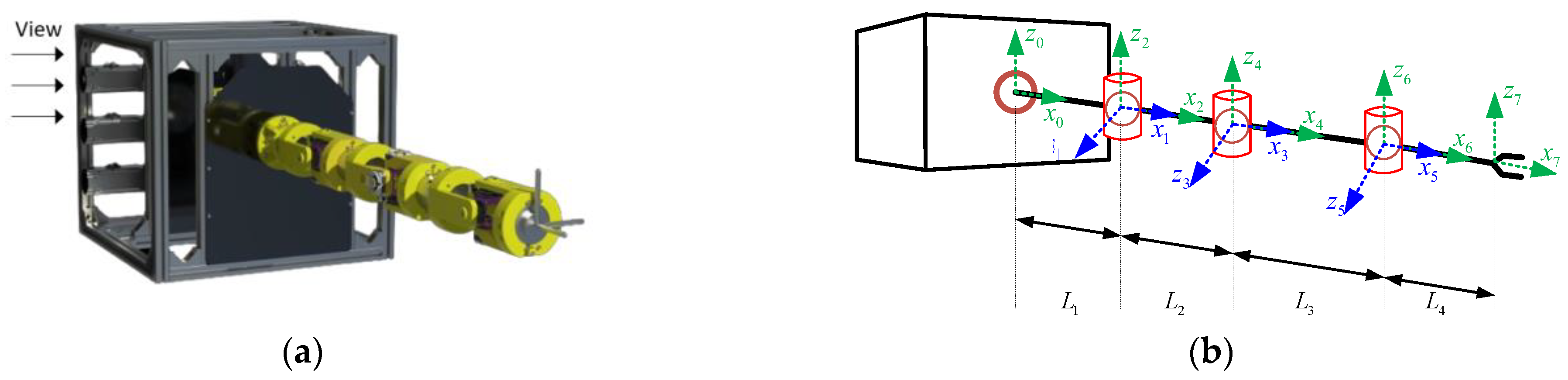
The forward kinematics is solved using the standard Denavit–Hartenberg (DH) method [24,25,26]. The coordinate system of the CDHR robot is illustrated in Figure 5. The DH parameters are listed in Table 1. Here, is the joint angle of the slave robot, and , , , and are the lengths of each of the links.

Figure 5.
Model of slave robot: (a) orientation view and (b) coordinate system of slave robot.

Table 1.
DH parameters of slave robot.
The position of the slave robot’s end-effector can be calculated based on the forward kinematics using the parameters listed in Table 1, which highlight the relationship between the coordinate systems of the base and end-effector of this robot. The results are as follows:
where , and denote the position of the slave robot; is the cosine of the ith joint angle; and is the sine of the ith joint angle.
As the flexibility of the cable robot increases, the number of degrees of freedom of the series manipulator increases. Therefore, computing its kinematics, especially inverse kinematics, becomes increasingly challenging. In this study, the Jacobian method is used to solve this problem. The Jacobian matrix shows the relationship between the angular velocity of the joint and linear velocity of the end-effector.
when is the vector of linear velocity, is the Jacobian matrix, and is the vector of angular velocity.
The pseudoinverse-method-based formula is expressed as follows:
where denotes the displacement of the joint angles, is a constant, and is the vector error between the desired position and position of the slave robot.
The angle of each joint is calculated as follows:
when are vectors of the joint angle at times and , respectively.
2.3.2. Master Device
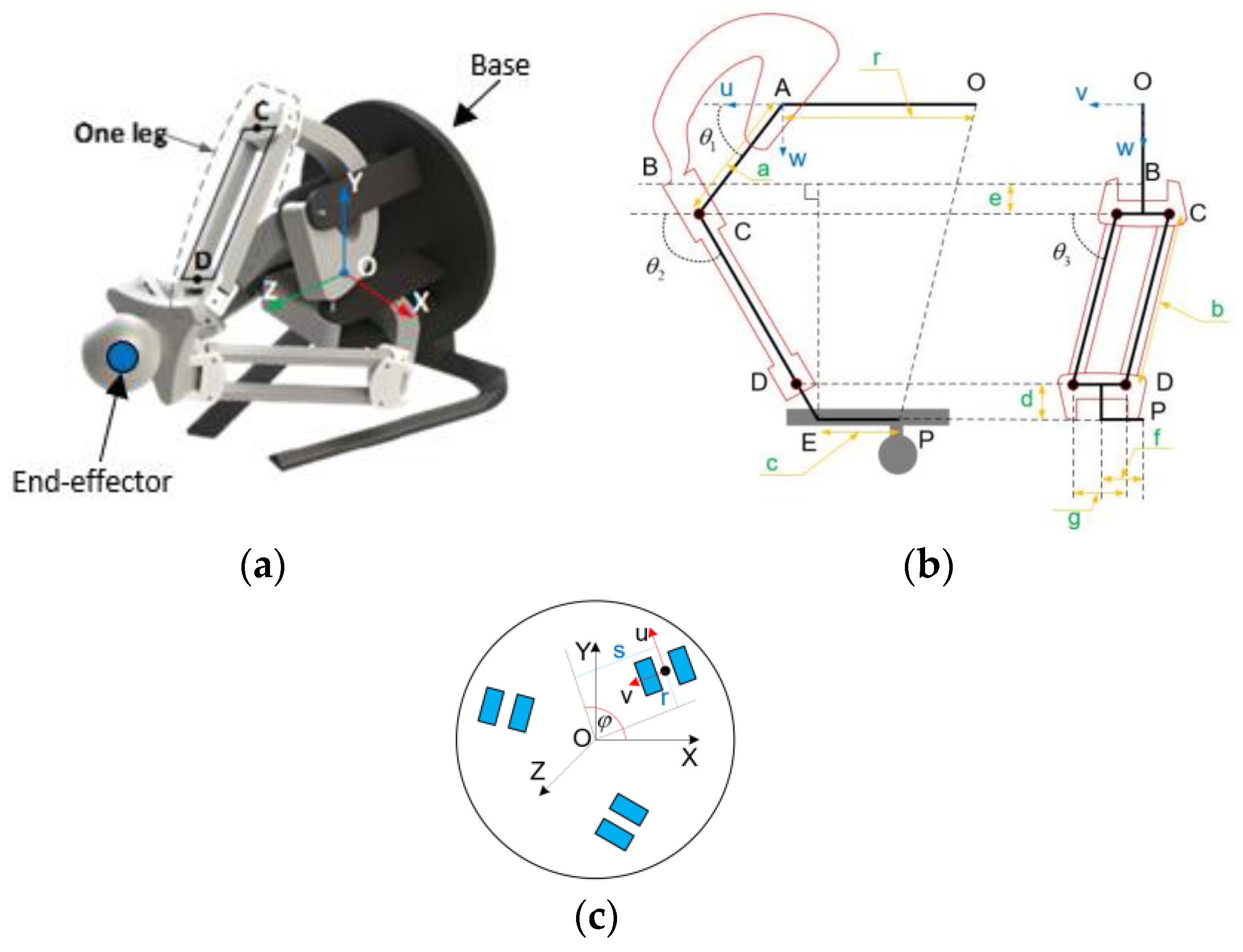
This haptic device comprises a base, an end-effector, and three legs. The original coordinate system of this device is centered at its base, as depicted in Figure 6a. To clarify the kinematics of Novint Falcon, the kinematics of one of its legs are illustrated in Figure 6b,c.
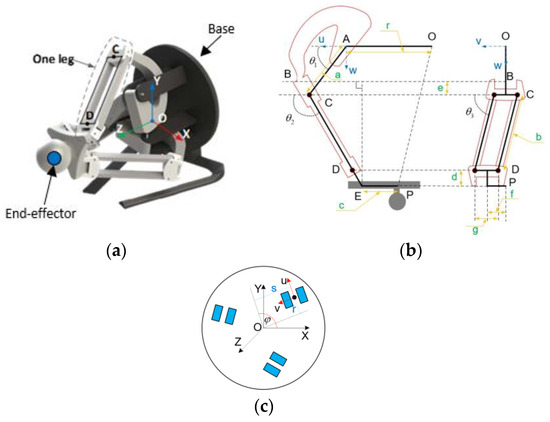
Figure 6.
Haptic model: (a) original coordinate system of the device. The description of axis system: (b) one leg; (c) base.
In Figure 6b,c O is the center of the XYZ coordinate system of the base, and P is the position of the end-effector of the haptic device. Moreover, UiViWi denote the relationship between the kinematics of ith leg and the original coordinate system of the device. is the angle of each joint of the ith leg (where i = 1, 2, 3).
The inverse kinematics mathematics are computed to determine the angle of each joint given the position of the end-effector. can be obtained as follows [27]:
The angle can be computed as follows:
where , , and [27].
After calculating and , the angle can be defined as follows:
The position of the end-effector can be obtained from the forward kinematics when the angle of each joint is known. However, because of the fact that the robot has a parallel structure, standard methods cannot be used to calculate these joint angles. Therefore, the equation of intersection of three spheres is used to determine the position of the haptic device [28].
3. Methodology
3.1. Position Mapping Method
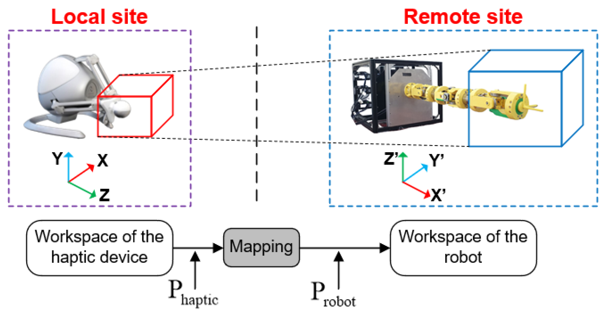
The main blocks of the teleoperation system are a local site and a remote site, as depicted in Figure 7. The haptic device and cable robot represent the local and remote sites, respectively, and the shapes and sizes of their workspaces are different. Therefore, we use the position mapping method to determine the positions of the cable robot and haptic device.
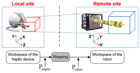
Figure 7.
Mapping between Novint Falcon and CDHR robot.
As depicted in Figure 7, the coordinate system and workspace of the haptic device are different from those of the cable robot. To control the remote site, the position of the haptic device is calculated using the position mapping method to determine the position of the cable robot, as follows [29]:
where is the position vector of the cable robot with respect to the axes, is the position vector of the haptic device with respect to the axes, is the constant matrix relative to the dimension workspaces after mapping from the haptic device to the cable robot, and denotes the vector offset.
The parameters and are selected such that the cable robot performs and operates safely within the entire workspace. The desired workspace of the haptic device is selected such that it is enclosed within the entire workspace. By adjusting and , the workspace of the cable robot can be determined after the proper value is detected.
3.2. Haptic Algorithm
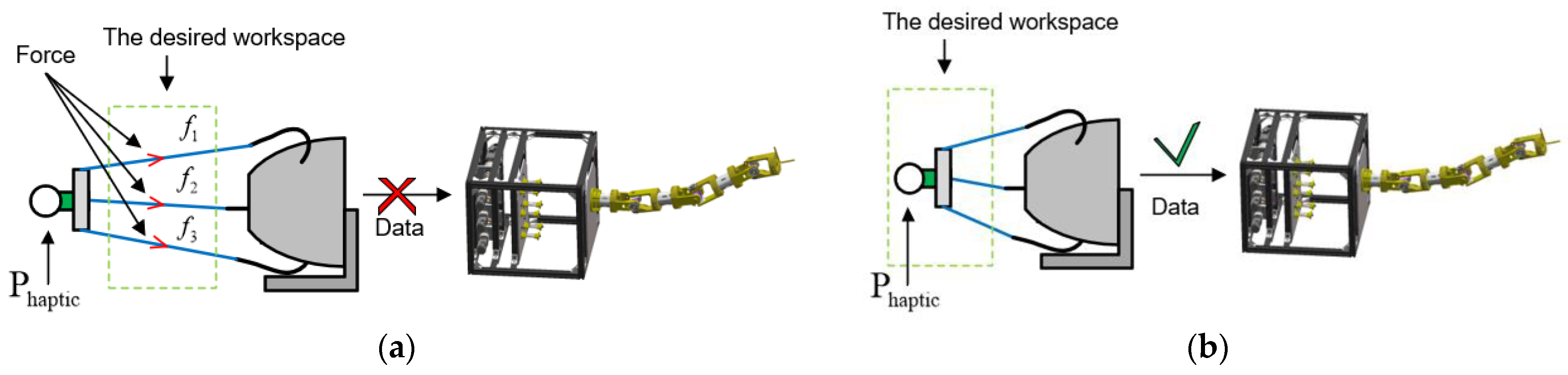
In Figure 8, system operation in the teleoperation and haptic modes is depicted. When the operator holds and controls the end-effector of the haptic device, a setpoint is generated and sent to the cable robot using the position mapping method. However, singularity appears in the outer region of the desired workspace, meaning that control over the robot can be lost. In this case, the system recalculates the setpoint and transitions from the teleoperation mode to the haptic mode. The force is linearly created based on the error of the position of the cable robot and the position at the border workspace in Figure 8a. In this stage, the cable robot is not functional until the end-effector of the haptic device returns to the desired workspace, as illustrated in Figure 8b.
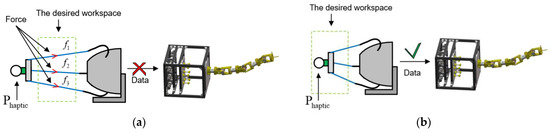
Figure 8.
Position of the haptic device in the (a) singularity area and (b) desired workspace.
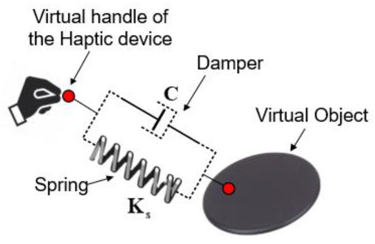
The haptic method helps the operator to get a better feel for the robot when controlling it to perform various tasks, and it prevents the robot from entering the singularity area. Force feedback influences the palm of the operator when the robot enters the singularity area to alert the operator about the limits of the safe operating area. The symbolic model of the haptic algorithm consisting of a damper, spring, and virtual object is depicted in Figure 9. The force of the haptic device appears once the symbolic model interacts with the virtual object. During this process, the spring serves as an elastic element and generates force against the direction of motion from the virtual handle. Moreover, the damper system, in combination with the spring, helps control robot stability and reduce robot velocity when the magnitude of the force increases abruptly [30,31].

Figure 9.
Symbolic model.
The formula for computing the elastic force is as follows:
where is the force vector; is the spring factor; and is the linear displacement of the spring. In this work, also denotes position displacement; the constant is the damping coefficient; and is the speed vector of the spring.
4. Simulations
In this section, the effectiveness of the proposed method is analyzed using the two solutions obtained through HIL simulation. The telerobotic system is modeled in MATLAB Simulink2022a and combined with the haptic device, as illustrated in Figure 1. Firstly, the inverse kinematics are verified using the Jacobian method, and then, the position mapping method is implemented in the HIL simulation system. Secondly, the haptic algorithm is applied to the teleoperation system, and its effectiveness is indicated upon appearance of the singularity point. During simulation, data related to the system are collected to evaluate the proposed method.
4.1. Verification Mapping Method
To control the telerobotic system, the Jacobian method must ensure stability of the inverse kinematics when the CDHR robot receives the setpoint from the haptic device. In the case study, two points, A and B, are considered. The home of the CDHR robot is point A, and its coordinates are [1027.4; −5.3, 5.3] mm. The desired position is point B. The results of verification of the Jacobian method are presented in Table 2.
Table 2.
Results obtained using Jacobian method.
The results presented in Table 2 indicate the effectiveness of the Jacobian method. Through five setpoints B, the position error of the CDHR robot is rather small, and its amplitude is within the interval mm. Therefore, the proposed method for determining the inverse kinematics of the redundant robot is highly precise.
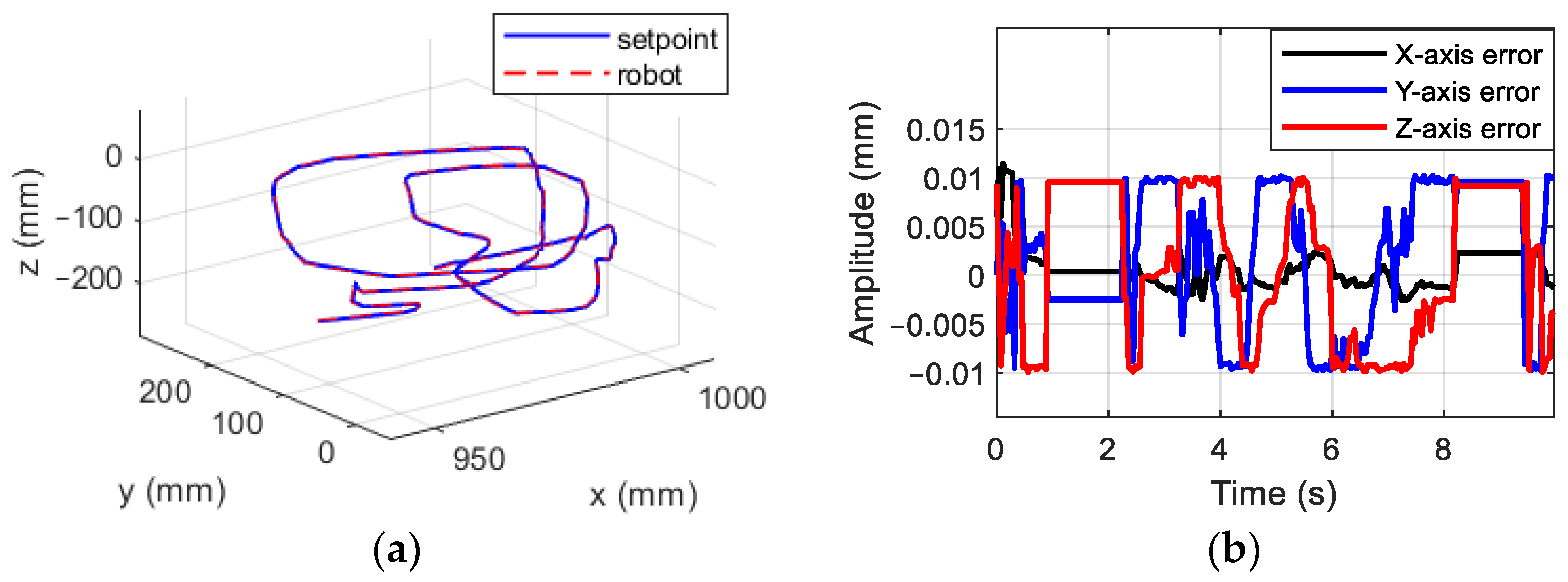
After application of the Jacobian method, the following case study of the telerobotic system was implemented. Position mapping was applied to the system with the parameters and . The results of the simulation process are presented in Figure 10.

Figure 10.
Simulation results: (a) trajectory planning along XYZ axes, and (b) error of CDHR robot.
After receiving the desired planning from the haptic device, the CDHR robot executes the inverse kinematic method to obtain the joint variables, which are also used as inputs to the Simscape model. The position of the CDHR robot’s end-effector, as determined using the Simscape model, is shown in Figure 10. The solid blue line denotes the setpoint, which is received from the haptic device after position mapping, and the red line denotes the position of the CDHR robot in the Simscape model. The CDHR robot tracks the reference of the desired planned path. The errors performance of the robot is shown in Figure 10b, and the amplitude of this error is within the interval [−0.01; 0.01] mm. Therefore, the position mapping method is highly accurate when applied to the teleoperation system.
4.2. Teleoperation Simulation
In this case study, the specifications of the position mapping method are selected based on trial and error to expand the workspace of the CDHR robot in the telerobotic system. Two parameter sets are selected, as summarized in Table 3. The workspaces corresponding to parameter sets 1 and 2 are presented in Figure 11a,b, respectively. The blue areas denote the workspace, and the red area is the singularity area. According to these figures, the workspace based on parameter set 2 is larger than that based on parameter set 1. Therefore, parameter set 2 is selected for the next step.
Table 3.
Parameter sets 1 and 2 used for mapping.
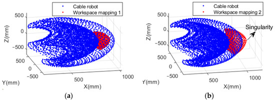
Figure 11.
Desired workspace of CDHR robot with (a) parameter set 1 and (b) parameter set 2.
Although the workspace is improved considerably, the singularity area appears. In this area, control over the robot may be lost, which is dangerous for the objects impacted by the robot. Therefore, haptics are used to solve this problem. The parameters of the haptic algorithm are depicted in Figure 12.
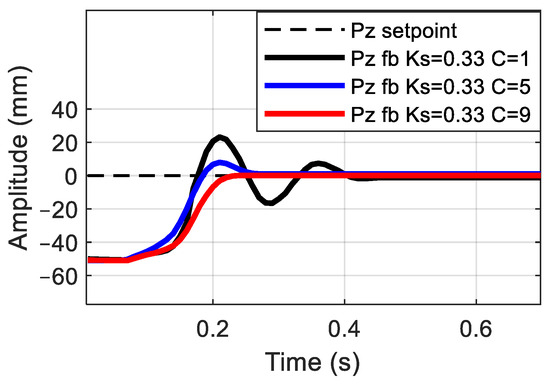
Figure 12.
Parameters of the haptic algorithm: and C.
First, the position of the haptic device is initialized with the value [80; 0; 0] mm. The operator pulls the end-effector of the haptic device to a random position along the Z-axis and releases it. The position error based on the initialized position and the end-effector can be determined, and then, forces are generated based on this error that act on the end-effector to control the haptic device’s return to the initialization position. Data pertaining to the force and position of the haptic device are collected through an Application Programming Interface (API) for communicating with the hardware device. Based on an observation of the response in Figure 12, we identified that the solid red line represents the proper value. This is because the respond does not have an overshoot, and the response time is better than that obtained in another case study. Therefore, the proper parameters of the haptic device are “ and ”. A comparison between the process simulations performed using the non-haptic and haptic algorithms verified the effectiveness of the algorithms. The simulation results are depicted in Figure 13.
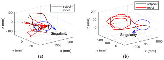
Figure 13.
CDHR robot in singularity region (a) without haptic algorithm and (b) with application of the haptic algorithm.
In Figure 13, the solid black line represents the setpoint in the local site, that is, the coordinates obtained after using the mapping method, and the red line denotes the position response of the CDHR robot measured at the end-effector of the robot. During verification, the position of the CDHR robot oscillates in Figure 13a in the singularity area outside the safe area. In this area, the CDHR robots operates by following unknown planning, which is dangerous for humans and impacts the entire system. Moreover, the safety factor cannot be ensured. Therefore, the haptic algorithm is applied to the system to prevent the occurrence of this phenomenon. The CDHR robot remains stable and does not follow the setpoint, despite the appearance of a singularity point in Figure 13b. Additionally, the responses along the X-axis and the generated force are depicted in Figure 14.
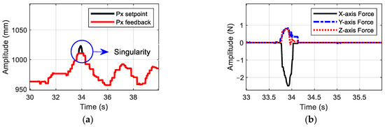
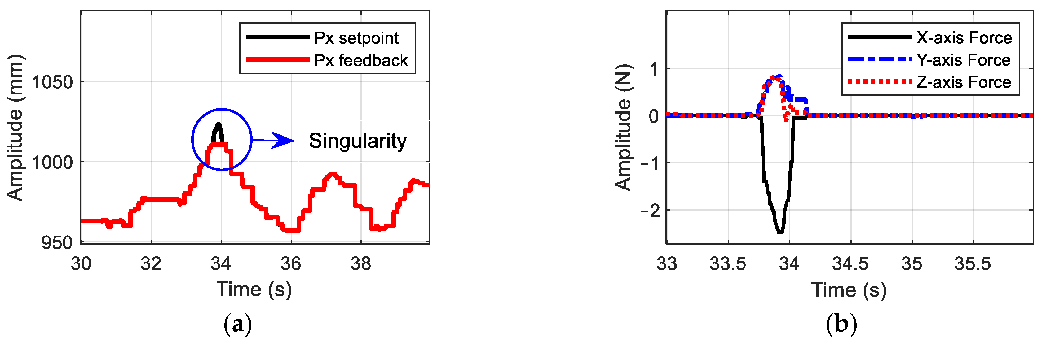
Figure 14.
Response of the slave system: (a) position along X axis in simulation and (b) force generated using the haptic device.
Figure 14a depicts the position response at the end-effector of the CDHR robot. The solid black line denotes a reference value, such as the desired coordinates of the robot, and the solid red line denotes the position information of the robot, as measured using the Simscape model. Figure 14b presents data pertaining to the force generated using the haptic device when the simulation process encounters the singularity phenomenon. When the operator pulls the haptic device along the X-axis into the singularity area and releases it, a force is generated based on the error between the setpoint at the local site and the position of the CDHR robot. The value of this force increases rapidly along the X-axis. This force combines with the forces along the Y- and Z-axes to ensure stability of the robot during performance and prevent the generation of large forces that cause the robot to oscillate, as shown in Figure 14b. The effectiveness is shown in the blue circle of Figure 14a; it means that the CDHR robot returns to their position after they are out of the permission space, although singularity appears.
5. Experiments
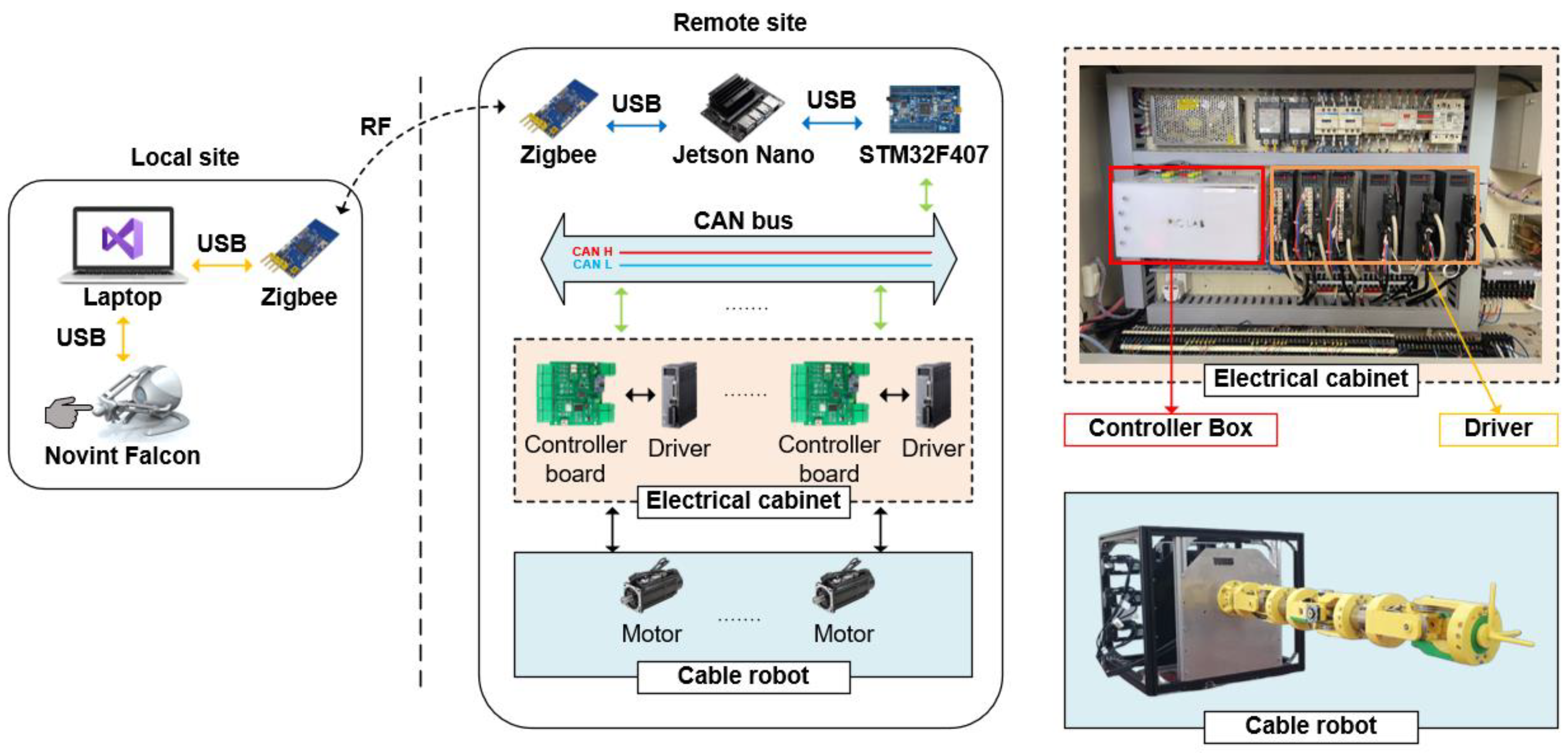
After ensuring the stability of the proposed method, the effectiveness of teleoperation control of the CDHR robot was tested experimentally to evaluate the performance of the system. The experiment involved a local site and remote site, as shown in Figure 15. The local site included the haptic device, a laptop, and a Zigbee module. The laptop was used to communicate with the haptic device and send data to the CDHR robot through the Zigbee protocol. The remote site consisted of a cable robot, an electrical cabinet, and an embedded computer. The Jetson Nano computer (NVIDIA, Santa Clara, CA, USA) was used to implement the algorithm of the CDHR robot. Then, the position signal after using the position method was sent to the electrical cabinet, which housed the distributed control system Control Area Network (CAN) and six-driver AC Servo. The CDHR robot was assembled using AC motors to control its motion through cables.
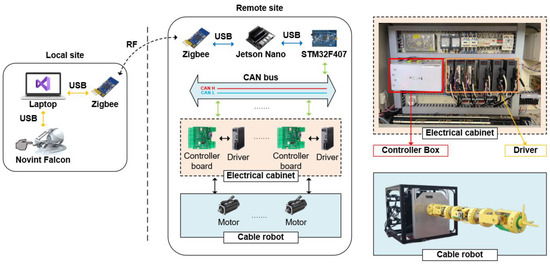
Figure 15.
Experimental testbench.
The details of the teleportation system are depicted in Figure 15. First, the operator holds and moves the Novint Falcon to generate the desired trajectory planning. These signals are converted into the reference position of the CDHR robot using the mapping method and sent to the remote site through the Zigbee communication channel. Second, the Jetson Nano solves the inverse kinematics using the Jacobian method to obtain the joint angles. These data are transmitted to the distributed control system, which consists of an STM32F407 and a controller board to operate the robot. This module uses the CAN bus protocol; this protocol is based on the application involving the car vehicle and can reduce the calculated volume and improve the performance of the system. Finally, the encoder sends joint angle feedback to the microcomputer, which is then presented on a graphic user interface (GUI). To demonstrate the effectiveness of the teleoperation system, the experiment is performed by holding the haptic device in the singularity area. The results are depicted in Figure 16.
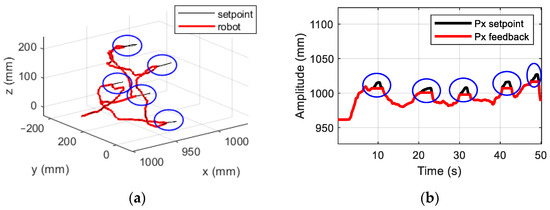
Figure 16.
Results of experiments: (a) planning of Novint Falcon using haptic algorithm, and (b) response signal of CDHR robot along X-axis.
To evaluate the effectiveness of the proposed method in the experiments, the haptic device was pulled into the singularity area multiple times, which is indicated by the blue circle in Figure 16a. The setpoint is highlighted in the black color, and setpoint data were collected through the API for communicating with the haptic device. The solid red line denotes the position of the end-effector of the CDHR robot, which was calculated from the encoder signals of the AC motor and the forward kinematics of the robot. In the area covered by the blue circle in Figure 16a, the robot seems to be immobile when its position does not follow the setpoint, and the overshooting phenomenon is avoided. The system switches to the haptic mode to generate a force that is applied to the palm of the operator for returning the device to the safe area. According to the results of the simulations and experiments, the proposed methods are not only effective but also resolve the challenges resulting from the inverse kinematics problem, the difference between the two workspaces, and singularity of the teleoperation system.
Estimates of the forces generated when the operator attempts to pull the master device to stop it moving outside the workspace are presented in Figure 17. Because the operator pulls the haptic device along the X-axis, the magnitude of force along this axis is greater than the sum of the forces along the Y- and Z-axes, which ensures device stability. According to Figure 17, the estimated force along the X axis is 4 N, and those along the Y- and Z-axes are 1 N. At this point, the slave robot is immobile until the master device is inside the safety area. The results show the effectiveness of the proposed method for teleoperation. The workspace was improved using the haptic algorithm, and the control method was successfully applied to the experimental model after verifying the HIL simulation system.
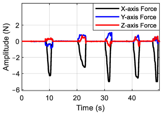
Figure 17.
Interaction of forces along the X-, Y-, and Z-axes.
6. Conclusions
In this study, a control method for a CDHR robot in a teleoperation system was proposed using the HIL simulation technique. Because the teleoperation system, consisting of a haptic device, called a delta robot, and a CDHR robot, was a large system, an HIL simulation system was developed to evaluate the safety of the teleoperation control algorithm and system before implementing it at the experimental scale. The CDHR had many degrees of freedom, and, therefore, its inverse kinematics were complex. For this reason, the Jacobian method was used to solve the inverse kinematics. Additionally, in the teleoperation system, the workspaces of the haptic device and CDHR robot were different in terms of size and coordinate systems. Therefore, the position mapping method was applied to utilize these workspaces. The parameters of this mapping method were selected using trial and error to increase the size of the CDHR robot’s workspace. The other challenges in teleoperation systems are the singularity area resulting from differences between workspaces. Therefore, a haptic algorithm was integrated into the proposed system to provide feedback to the operator for preventing the CDHR from moving into the singularity area. A few simulations were conducted using the proposed HIL simulation scheme in the MATLAB Simscape environment to evaluate the teleoperation control method developed herein. The results indicated that the challenges related to the inverse kinematics, workspace differences, and singularity of the workspace were solved. Furthermore, the size of the workspace was increased considerably while maintaining the system stability and safety.
Author Contributions
Conceptualization, D.T.T., T.D.N. and M.K.T.; methodology, D.T.T., T.D.N. and M.K.T.; software, T.D.N. and M.K.T.; validation, T.D.N. and M.K.T.; formal analysis, T.D.N. and M.K.T.; investigation, D.T.T., T.D.N. and M.K.T.; resources, D.T.T., T.D.N. and M.K.T.; data curation, T.D.N. and M.K.T.; writing—original draft preparation, T.D.N. and M.K.T.; writing—review and editing, D.T.T. and K.K.A.; visualization, D.T.T., T.D.N. and M.K.T.; supervision, D.T.T. and K.K.A.; project administration, K.K.A.; funding acquisition, K.K.A. All authors have read and agreed to the published version of the manuscript.
Funding
This work was supported by Korea Hydro & Nuclear Power Co and Ulsan (2023) and “Regional Innovation Strategy (RIS)” through the National Research Foundation of Korea (NRF) funded by the Ministry of Education (MOE) (2021RIS-003).
Institutional Review Board Statement
Not applicable.
Informed Consent Statement
Not applicable.
Data Availability Statement
Data is contained within the article.
Acknowledgments
Thank you for the support from Ho Chi Minh City University Technology and Education, Vietnam, and University of Ulsan, South of Korea.
Conflicts of Interest
The authors declare no conflicts of interest.
References
- Nitendra Nath, T.; Darren, E.; Dawson, M. Teleoperation with Kinematically Redundant Robot Manipulators with Sub-Task Objectives. Robotica 2008, 27, 1027–1038. [Google Scholar] [CrossRef]
- Walker, M.E.; Hedayati, H.; Szafir, D. Robot Teleoperation with Augmented Reality Virtual Surrogates. In Proceedings of the 4th ACM/IEEE International Conference on Human-Robot Interaction (HRI), La Jolla, CA, USA, 9–13 March 2019. [Google Scholar] [CrossRef]
- Scibilia, A.; Pedrocchi, N.; Fortuna, L. Modeling Nonlinear Dynamics in Human–Machine Interaction. IEEE Access 2023, 11, 58664–58678. [Google Scholar] [CrossRef]
- Da Sun, F.N.; Du, H. Application of Wave-Variable Control to Bilateral Teleoperation Systems: A Survey; Elsevier: Amsterdam, The Netherlands, 2014. [Google Scholar] [CrossRef]
- Linping Chan, F.N.; Stirling, D. Application of adaptive controllers in teleoperation systems: A survey. IEEE Trans. Hum. Mach. Syst. 2014, 45, 1–12. [Google Scholar] [CrossRef]
- Fiorini, R.M.A.P. A Review of Bilateral Teleoperation Algorithms. Acta Polytech. Hung. 2016, 13, 191–208. [Google Scholar]
- Liu, Y.-C.; Chopra, N. Control of semi-autonomous teleoperation system with time delays. Automatica 2013, 49, 1553–1565. [Google Scholar] [CrossRef]
- Zhang, S.; Yuan, S.; Yu, X.; Kong, L.; Li, Q.; Li, G. Adaptive Neural Network Fixed-Time Control Design for Bilateral Teleoperation with Time Delay. IEEE Trans. Cybern. 2021, 52, 9756–9769. [Google Scholar] [CrossRef] [PubMed]
- Zhang, H.; Song, A.; Shen, S. Adaptive Finite-Time Control Scheme for Teleoperation with Time-Varying Delay and Uncertainties. IEEE Trans. Syst. 2018, 6, 40940–40949. [Google Scholar] [CrossRef]
- Lu, S.; Ban, Y.; Zhang, X.; Yang, B.; Liu, S.; Yin, L.; Zheng, W. Adaptive control of time delay teleoperation system with uncertain dynamics. Percept. Recovery Augment. Med. Robot. 2022, 16, 928863. [Google Scholar] [CrossRef] [PubMed]
- Martín-Barrio, A.; Roldán, J.J.; Terrile, S.; Del Cerro, J.; Barrientos, A. Application of immersive technologies and natural language to hyper-redundant robot teleoperation. Virtual Real. 2019, 4, 541–555. [Google Scholar] [CrossRef]
- Tran, D.T.; Tran, T.L.; Duong, M.T.; Dao, H.V.; Ahn, K.K. The CCD-Algebraic Algorithm to solve the inverse kinematic and control the rotation of 6-DOF redundant manipulator in three spatial dimensions. In Proceedings of the 2022 25th International Conference on Mechatronics Technology (ICMT), Kaohsiung, Taiwan, 18–21 November 2022; pp. 1–6. [Google Scholar]
- Lv, H.; Pang, Z.; Bhimavarapu, K.; Yang, G. Impacts of Wireless on Robot Control: The Network Hardware-in-the-Loop Simulation Framework and Real-Life Comparisons. IEEE Trans. Ind. Inform. 2023, 19, 9255–9265. [Google Scholar] [CrossRef]
- Qi, C.; Ren, A.; Gao, F.; Zhao, X.; Wang, Q.; Sun, Q. Compensation of Velocity Divergence Caused by Dynamic Response for Hardware-in-the-Loop Docking Simulator. IEEE/ASME Trans. Mechatron. 2016, 22, 422–432. [Google Scholar] [CrossRef]
- He, J.; Shen, M. Hybrid Force/Velocity Control for Simulating Contact Dynamics of Satellite Robots on a Hardware-in-the-Loop Simulator. IEEE Access 2022, 10, 59277–59289. [Google Scholar] [CrossRef]
- He, J.; Shen, M.; Gao, F. A Passivity-Based Velocity Control Method of Hardware-in-the-Loop Simulation for Space Robotic Operations. Aerospace 2022, 9, 368. [Google Scholar] [CrossRef]
- Nabi, S.; Balike, M.; Allen, J.; Rzemien, K. An Overview of Hardware-In-the-Loop Testing Systems at Visteon. In Proceedings of the SAE 2004 World Congress & Exhibition, Sydney, Australia, 17–21 May 2004. [Google Scholar] [CrossRef]
- Barreras, J.V.; Fleischer, C.; Christensen, A.E.; Swierczynski, M.; Schaltz, E.; Andreasen, S.J.; Sauer, D.U. An Advanced HIL Simulation Battery Model for Battery Management System Testing. IEEE Trans. Ind. Appl. 2016, 52, 5086–5099. [Google Scholar] [CrossRef]
- Mihalič, F.; Truntič, M.; Hren, A. Hardware-in-the-Loop Simulations: A Historical Overview of Engineering Challenges. Electronics 2022, 11, 2462. [Google Scholar] [CrossRef]
- Herrmann, S.; Kluess, D.; Kaehler, M.; Grawe, R.; Rachholz, R.; Souffrant, R.; Zierath, J.; Bader, R.; Woernle, C. A Novel Approach for Dynamic Testing of Total Hip Dislocation under Physiological Conditions. PLoS ONE 2015, 10, e0145798. [Google Scholar] [CrossRef] [PubMed]
- Inés Tejado, J.S.; Pérez, E.; Torres, D.; Blas, M. Vinagre, Low-cost Hardware-in-the-loop Testbed of a Mobile Robot to Support Learning in Automatic Control and Robotics. ScienceDirect 2016, 49, 242–247. [Google Scholar]
- Fedak, V.; Durovsky, F.; Uveges, R.; Kyslan, K.; Lacko, M. HIL Simulator of Drives of an Industrial Robot with 6 DOF. Elektron. Elektrotech. 2015, 21, 14–19. [Google Scholar] [CrossRef]
- Mora-Soto, M.E.; Maldonado-Romo, J.; Rodríguez-Molina, A.; Aldape-Pérez, M. Building a Realistic Virtual Simulator for Unmanned Aerial Vehicle Teleoperation. Appl. Sci. 2021, 11, 12018. [Google Scholar] [CrossRef]
- Nguyen, N.T.; Nguyen, T.N.T.; Tong, H.N.; Truong, H.V.A.; Tran, D.T. Dynamic Parameter Identification based on the Least Squares method for a 6-DOF Manipulator. In Proceedings of the 2023 International Conference on System Science and Engineering (ICSSE), Ho Chi Minh, Vietnam, 27–28 July 2023; pp. 301–305. [Google Scholar]
- Tran, D.T.; Nguyen, T.L.; Ha, T.T.; Hoang, H. Design Model and Synchronous Controllers for a Dual 3-DOF Manipulator based on CAN Network. In Proceedings of the 2023 International Conference on System Science and Engineering (ICSSE), Ho Chi Minh, Vietnam, 27–28 July 2023; pp. 287–291. [Google Scholar]
- Tran, M.P.; Ha, T.B.; Tong, H.N.; Duc, T.T. Nonlinear Controller with Dynamic Compensation for 6-DOF Manipulator in Practice. J. Tech. Educ. Sci. 2023, 75, 31–39. [Google Scholar] [CrossRef]
- Karbasizadeh, N.; Zarei, M.; Aflakian, A.; Masouleh, M.T.; Kalhor, A. Experimental dynamic identification and model feed-forward control of Novint Falcon haptic device. Mechatronics 2018, 51, 19–30. [Google Scholar] [CrossRef]
- Delta Robot Kinematics. Available online: https://hypertriangle.com/~alex/delta-robot-tutorial/ (accessed on 27 July 2009).
- Mokogwu, C.N.; Hashtrudi-Zaad, K. A hybrid position–rate teleoperation system. Robot. Auton. Syst. 2021, 141, 103781. [Google Scholar] [CrossRef]
- Ju, Z.; Yang, C.; Li, Z.; Cheng, L.; Ma, H. Teleoperation of humanoid baxter robot using haptic feedback. In Proceedings of the 2014 International Conference on Multisensor Fusion and Information Integration for Intelligent Systems (MFI), Beijing, China, 28–29 September 2014; pp. 1–6. [Google Scholar]
- Qin, L.; Huang, F.; Chen, Z.; Song, W.; Zhu, S. Teleoperation Control Design with Virtual Force Feedback for the Cable-Driven Hyper-Redundant Continuum Manipulator. Appl. Sci. 2020, 10, 8031. [Google Scholar] [CrossRef]


Disclaimer/Publisher’s Note: The statements, opinions and data contained in all publications are solely those of the individual author(s) and contributor(s) and not of MDPI and/or the editor(s). MDPI and/or the editor(s) disclaim responsibility for any injury to people or property resulting from any ideas, methods, instructions or products referred to in the content. |
© 2024 by the authors. Licensee MDPI, Basel, Switzerland. This article is an open access article distributed under the terms and conditions of the Creative Commons Attribution (CC BY) license (https://creativecommons.org/licenses/by/4.0/).