Article

A Rapid and Inexpensive Method for Finding the Basic Parameters of Involute Helical Gears

1
Mechanics and Technologies Department, “Stefan cel Mare” University of Suceava, 720229 Suceava, Romania
2
Mechanical Engineering, Mechatronics and Robotics Department, “Gheorghe Asachi” Technical University, 700050 Iasi, Romania
3
Technical Sciences Academy of Romania, 26 Dacia Blvd, 030167 Bucharest, Romania
*
Author to whom correspondence should be addressed.
Appl. Sci. 2024, 14(5), 2043; https://doi.org/10.3390/app14052043
Submission received: 31 January 2024 / Revised: 26 February 2024 / Accepted: 27 February 2024 / Published: 29 February 2024
(This article belongs to the Special Issue Modern Research of Gears and Power Transmission)

Abstract

:
The paper proposes a rapid, straightforward, and inexpensive method for finding the basic parameters of helical gears with an involute profile. The basic parameters envisaged are the normal module, normal profile shift coefficient, and the helix angle. The proposed method uses balls introduced between the teeth and, thus, the contact with the measuring device surfaces is of the point type, and the centres of the balls are positioned symmetrically with respect to the measuring direction. The condition that the centre of the ball occupies an imposed position is mandatory. Additionally, there is the condition of the positions of the contact points between the balls and the flanks of the teeth. Two sets of balls of different sizes are necessary for a measurement. The conditions of the balls’ positioning lead to a system of five unknowns. The methodology of solving the system is detailed and the method is exemplified for an actual helical gear. The new proposed method is based on the distance over pins but, using balls, presents the following advantages: It can be applied equally to all gears, regardless of the odd or even number of teeth. Furthermore, the dimension to be measured is singular compared to the dimension over pins when a maximum value must be found from several measurements.

1. Introduction

Everyday engineering applications require new mechanisms which generate functions. To synthesise these mechanisms, the Machines and Mechanisms Theory must be applied. Thus, new dimensional constructive solutions of mechanisms, which, for a stipulated law of motion of the driving element, ensure a specified law of motion of the driven element [1], are designed. The problem can be solved in two ways: (a) the law of motion of the driven element is achieved with precision, and (b) the law of motion approximates, with a pre-stipulated accuracy, the imposed theoretical law. A more in-depth analysis shows that obtaining a solution which gives an imposed theoretical law of motion is an idealistic impossible task, mainly due to the backlash from the pairs of the mechanism, the manufacturing errors of the dimensions of the elements [2], and the deformations of the elements. Nevertheless, in a first approximation, it is accepted that all elements of the mechanism are perfectly rigid, the backlash from the kinematic pairs is zero, and the constructive dimensions of the elements are precisely machined. Under these simplifying hypotheses, one of the frequently met problems in engineering practice is finding the constructive solutions which allow, for the driven element, a motion identical to the motion of the driving element—these are the homokinetic mechanisms; Seherr-Thoss [3] and Dudita [4] present a series of constructive solutions of homokinetic mechanisms. An initial method to classify these mechanisms revolves round the relative position between the axes of the driven and driving element. In the broadest scenario when the driving and the driven axis are not co-planar, the tripodic transmissions are a solution of homokinetic coupling. Innocenti [5] presents a constructive solution where the tripodic coupling is achieved by pairs of point–surface type, while Qiu [6] presents a constructive solution of tripodic coupling with three curve–curve-type contacts. Notably for both methodologies, the mechanisms preserve homokinetic characteristics, even as the axes adjust their relative positioning over time. In the context of spherical mechanisms, an example of homokinetic mechanism is the Rzeppa coupling [7]. For planar mechanisms, where the input and output axes are parallel, the technical literature offers numerous constructive solutions for homokinetic mechanisms, with a prime example being the parallelogram mechanism. In instances where both axes retain fixed spatial positions, and the driving and driven element have rotation motion, the most convenient solution for achieving a homokinetic mechanism consists of a mechanism made of three elements only: the ground, the driving element, and the driven element. It is demonstrable that regardless of the position of the input and output axes, the transmission of motion between the mobile elements is made via a higher pair aligning with the overarching definition of cam mechanisms. This is a class 1 higher pair for the crossed axes and class 4 higher pair for the spherical mechanisms or plane parallel mechanisms [8]. This remark indicates the fact that the gear mechanisms are a special category of cam mechanisms. Additionally, one can attain broader relevance in the context of gear mechanisms by recalling the transmission ratio, generally defined as
i 12 = ω 1 ω 2
where ω 1 and ω 2 are the angular velocities of the driven and driving axes, respectively. In the case of gear mechanisms, in most situations, they should ensure the transmission of motion with a rigorously constant ratio:
i 12 = c o n s t .
The surfaces that give rise to the kinematic higher pair are typically referred to as “flanks”. Specific criteria, as outlined in the pertinent technical literature [9,10], must be satisfied by these flanks to facilitate the transmission of rotational motion at a constant ratio.
For mechanisms with parallel axes, the flanks of the spur gears can be described as ruled surfaces, with their generatrixes lying parallel to the wheel axes. The whole gearing process can be studied in a section normal to the axes of the wheels (frontal plane). The intersection between the flanks and the plane normal to the axes of the wheels are named profiles. In this case, the condition of two toothed wheels to maintain a constant transmission ratio is derived from the fundamental law of gearing. This law dictates that for two profiles designed to mesh with a constant transmission ratio, the common normal at their point of contact should always pass through a fixed point [11,12]. This point known as the “pitch point “ and lies along the centre line, dividing it in a ratio inversely proportional to the transmission ratio. Therefore, if there are stipulated the centers distance, the transmission ratio and one of the profiles, then, based on the fundamental law of gearing, the profile of the conjugate wheel can be found. From a practical point of view, an extremely pertinent problem is determining a profile curve that, by the gearing fundamental law, conducts to a curve of the same type of the conjugate profile. Therefore, the manufacturing technology of both teethed wheels is unified to a unique one and the costs of the transmission are thus substantially reduced. The single curve that satisfies this condition is the circle involute. This property of the involute makes possible the wide spread of spur gears with involute teeth in engineering applications. The parameters defining the involute teeth are used in all three stages: design, machining, and control. The last stage has a distinct importance since by finding the parameters which define the geometry of the teeth, one can estimate the manner of the fabrication process [13,14], ensure the accuracy requirements imposed on the gear during the design step, and thus certify the appropriate running of the assembly [15,16] from which it belongs. Concerning the control methods of the gears, these evolved from classical ones [17,18], when the over teeth and over pins/over balls dimensions were verified, to modern procedures [19,20,21,22]. One can mention a modern control method of gears which assimilates the helical gears with helical screws [23].

2. Materials and Methods

2.1. Aspects Concerning the Geometry of Spur Gears with Involute Teeth

Given that the geometric and kinematic evaluations of helical gears can ultimately be deduced from the analysis of a spur gear, we first consider the geometric and kinematic parameters of spur gears, before moving on to understanding those of a helical gear. From the above, it is plausible to leverage the fundamental law of gearing to determine a conjugate profile that corresponds to any given profile. From a manufacturing perspective, it is advantageous if both profiles are curves of the same type. Among all the planar curves, the involute of the circle is unique as its conjugate is of the same type. This curve is defined by a point attached to a mobile straight line that, without any slippage, rolls along an affixed circle, termed the base circle C b , as shown in Figure 1.
In the initial position, the mobile straight line takes the position Δ 0 . Three fixed points on this straight line are considered: A 0 0 coincides to the point of tangency, A 0 is inside the base circle, and A 0 + . Allowing the straight line to roll without slipping over the base circle C b , it occupies a current position Δ where the tangency with the base circle is in the point T . The three points fixed to the generating straight line take the current positions A 0 , A , and A + respectively, describing during the motion of a normal involute, a prolate involute, and a curtate involute (Figure 1).
The condition of pure rolling stipulates that the length of the line segment A 0 T ¯ should equal the arc length A 0 0 T . Based on this remark, the polar parametric equations of the normal involute can be obtained:
ρ y = O A 0 = r b cos α y θ y = A 0 0 O A 0 = tan α y α y
The function that appears in the definition of the θ y angle is denoted i n v α and is defined as
i n v α = tan α α , [ α ] r a d
and is frequently met in the theory of gearing. The α y parameter from Equation (3) is the pressure angle of the normal involute on the base circle C y of radius r y . Within the theory of involute gears, we can identify a circle by specifying the pressure angle of the normal involute profile. This profile is created using a base circle with an already established centre and radius.
Based on relations (3) and (4), the cartesian parametric equations of any of the three involutes can be obtained:
x ( α ) = r b cos α sin ( i n v α ) + a sin ( tan α ) y ( α ) = r b cos α cos ( i n v α ) + a cos ( tan α )
where for a < 0 the prolate involute is obtained, for a = 0 the normal involute is obtained, and for a > 0 the curtate involute is obtained.
Another observation with important consequences concerns the fact that the length of the segment T A 0 is the curvature radius of the normal involute in the current point A 0 .
ρ c = l e n g t h ( T A 0 ) = r b tan α
As the tooth count of a gear wheel approaches infinity, it logically follows that the radius of the base circle expands towards infinity as well. Thus, a gear wheel evolves into a rack with an infinite number of teeth and the curvature radius of the rack profile also expands towards infinity. This implies that the profile of an involute gear rack takes the form of a straight line, as depicted in Figure 2. The base line of the rack Δ 0 is the line alongside which the thickness of the tooth s 0 is equal to the space width e 0 . Consequently, it corresponds to half the pitch of the rack (maintaining consistency across any section parallel to the direction of motion):
s 0 = e 0 = p 0 / 2
with
p 0 = π m
where m is a parameter with dimension of length and taking standard values. The reference straight line divides the tooth into two zones:
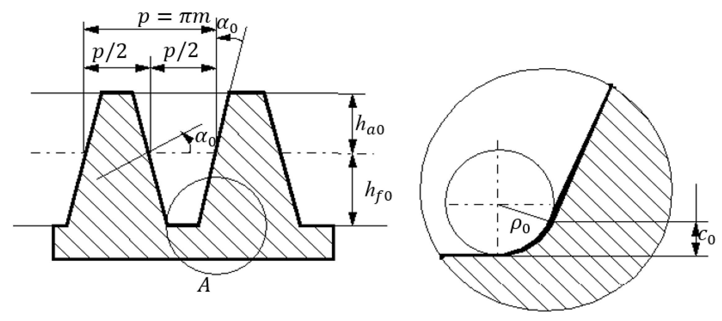
  • The addendum, of height
    h a 0 = h a 0 m , h a 0 = 1 ( I S O v a l u e ) ;
  • The dedendum. As can be noticed from the detail A, the tooth is cut on the inferior zone of a length
    c 0 = c 0 m , c 0 = 0.25 ( ISO value )
The reference height of the dedendum becomes
h f 0 = h f 0 m = ( h a 0 + c 0 ) m
For a complete definition of the geometry of the rack, additional specifications must be stipulated:
  • The pressure angle of the straight profile:
    α 0 = 20 ° ;
  • The filleting radius ρ 0 at the root of the tooth:
    ρ 0 = c 0 1 sin α 0 m 0.38 m
As a conclusion, the profile of the basic rack is defined by the module m , the pressure angle α 0 , the reference addendum coefficient h a 0 = 1 , and the coefficient of radial backlash c 0 = 0.25 .
The gear with involute teeth is defined using the basic rack. The definition parameters require adherence to two specific conditions:
  • The gearing is accomplished without backlash between the flanks;
  • The gearing is accomplished with standard radial backlash c 0
The two conditions are sufficient for the complete definition of the gear. The centroids of the relative motion between the wheel and the base rack are represented (Figure 3) by the pitch circle of the gear c d of diameter
d = m z ,
and the rolling straight line of the rack Δ w parallel to the reference line Δ 0 , but at a distance from this, with the quantity X named profile shift and expressed as
X = m x
The profile shift coefficient x of the gear is considered:
x = 0 when the straight line Δ w is tangent to the pitch circle;
x < 0 when Δ w intersects the pitch circle;
x > 0 when Δ w is external to the pitch circle.
In conclusion, with stipulated parameters for the shape and dimensions of the basic rack, the toothed wheel is fully characterized by the next three parameters:
1.
The number of teeth z , which describes the dimension of the wheel;
2.
The module m , which describes the dimension of the tooth;
3.
The profile shift coefficient x , which describes the shape of the tooth.
A precise method for manufacturing the involute gears is gear generation, wherein the resultant gear is conceived as the envelope of a distinctive series of positions of a toothed cutting tool. This procedure requires a relative motion between the gear blank and the tool mimicking the motion that would otherwise be present between the tool and the final, machined gear. One manufacturing technique uses a tool which mirrors the profile of the generating rack (conjugate to the basic rack).
To highlight the impact of the number of teeth and of the profile shift coefficient on gear machining, a simulation program was developed. This simulation experiment incorporated two different configurations of tooth count, z = 5 and z = 10 , along with three distinct values attributed to the profile shift coefficient. Figure 4 shows the results of the simulation. It is evident that negative values of the profile shift coefficient led to an undercutting phenomenon which involves the removal of tooth material within the dedendum zone. Conversely, positively large values result in overcutting of the tooth. Both phenomena are more pronounced when the tooth count of the gear wheel z is smaller.
Concerning the adoption of the profile shift coefficient of a gearing, essential observations are as follows:
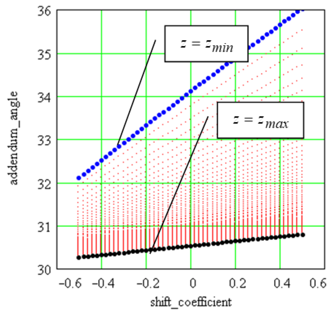
  • The first remark is related to the effect of the profile shift coefficient upon the centre distance; in order to achieve a standard centre distance, gear correction must be performed;
  • The second observation refers to the gear synthesis methodology; to ensure satisfactory kinematic and dynamic behaviour, a gear mechanism needs to conform to all stipulated conditions for smooth operation. Such criteria can be defined by a condition formulated as follows:
    F k ( m , z 1 , z 2 , x 1 , x 2 ) 0 ,         k = 1 ÷ n
    where n is the number of imposed criteria. For the imposed module, the relation (16) becomes
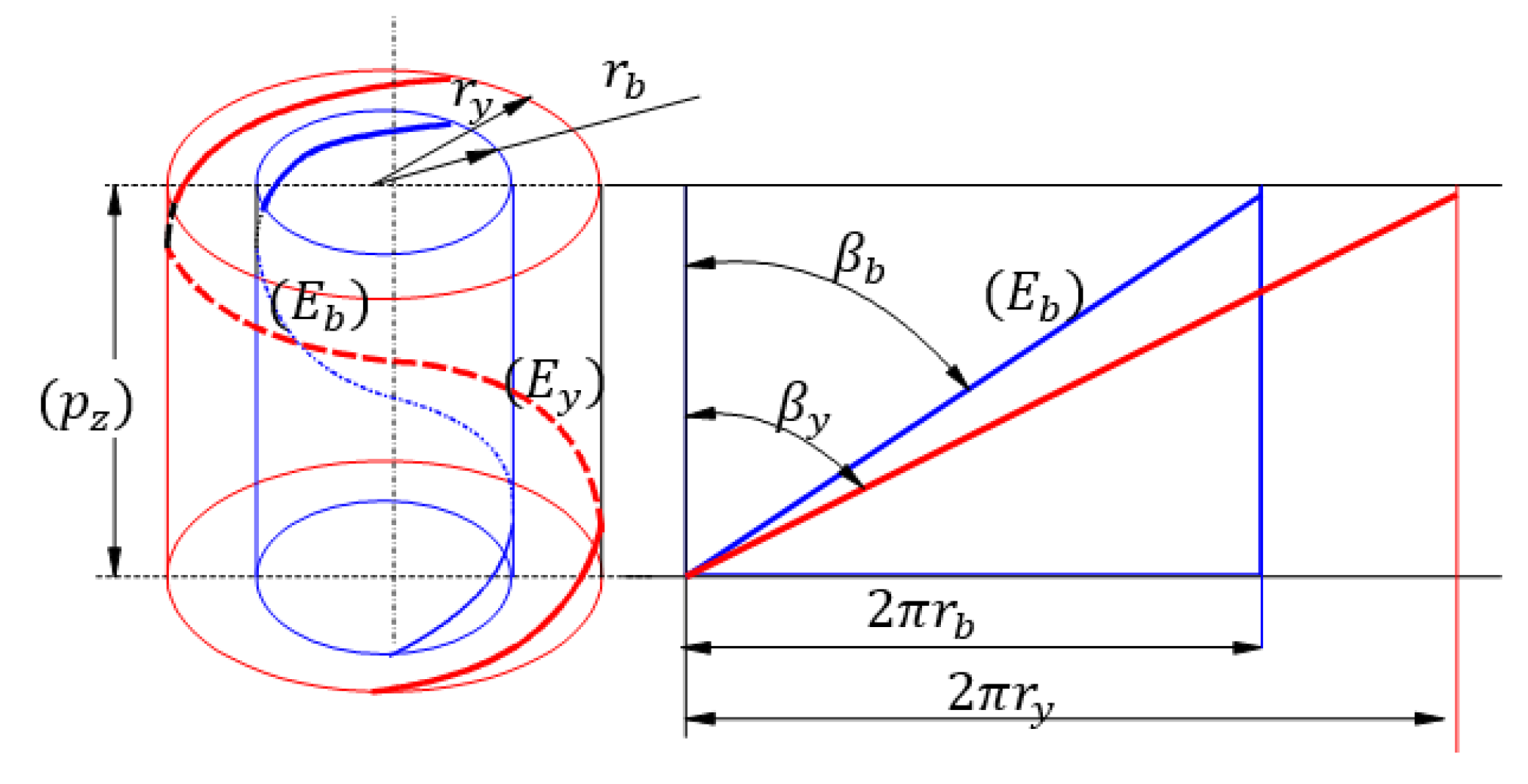
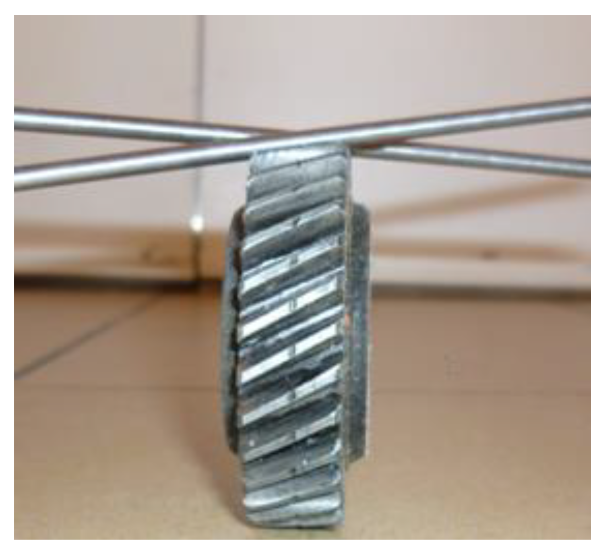
    f k ( z 1 , z 2 , x 1 , x 2 ) 0
If we consider only the equality from Equation (17) and treat the profile shift coefficients x 1 and x 2 while z 1 and z 2 are regarded as parameters, the equation of a curve is obtained:
ϕ k ( x 1 , x 2 ) 0
This curve divides the plane x 1 x 2 into two regions: one where the criterion is satisfied, and another where it is not. For a gearing with a stipulated number of teeth, the intersection of all regions where all the n conditions are verified will represent, in the x 1 x 2 plane, a closed domain [24], where all the imposed criteria of correct running will be satisfied. The boundary of this domain is named the “locking contour”. Knowing the locking contour allows, for a given pair of teeth, the correct and operative choice of the profile shift coefficients.

2.2. Helical Gears

In order to define the profile of a helical gear, a base cylinder is set on a plane ( P ) , as shown in Figure 5. In the ( P ) plane, ( Δ ) is considered the straight line that makes the angle ( β b ) with the generatrix of the cylinder tangent to the plane. By rolling the plane ( P ) without slipping, a ruled surface is generated which can be used as a tooth flank. During the process of flank creation, the points of the straight line ( Δ ) will sit on the base cylinder as a helix with constant pitch ( E b ) , named the base helix. Each point of the straight line ( Δ ) describes an involute generated using the circles of radius ( r b ) (the radius of the base cylinder). As an example, in the foreground plane, the involute ( e ) is generated and in the background plane, the involute ( e ) is generated. All involute curves commence from the base cylinder and, due to their origin at the base helix, preserve a uniform angular discrepancy across the length of the cylinder’s generatrix.
The generation process of the flank’s surface yields the conclusion that it constitutes a helical involute ruled surface. The intersection of the flank with an arbitrary cylinder of radius r y coaxial to the base cylinder is a helix ( E y ) . Based on Figure 6, where the unfolded cylinders are also shown, the inclination angle β y of the helix on the cylinder of radius r y is found. It must be noted that both helices share the same axial pitch.
tan ( β y ) = 2 π r y p z tan ( β b ) = 2 π r b p z tan ( β y ) = tan ( β b ) r y r b
We introduce the convention that the parameters from a frontal section (normal to the axis of the wheel) are denoted with the index “t”. Thus, the relation (19) becomes
tan ( β y ) = tan ( β y ) cos ( α y t )
where α y t represents the pressure angle of the involute ( e ) on the circle of radius r y , as in Figure 6. Given that the gearing interaction between the profiles in any section perpendicular to the axes of the wheels mirrors that of two spur gears, it can be asserted that the rack’s profile will be linear across all frontal sections. Additionally, with helical teeth, the interaction between the teeth of the wheel and the rack occurs along a straight line ( Δ ) . It is noteworthy that this line no longer aligns perpendicularly to the direction of displacement. As a result, it becomes apparent that the flank of the helical rack is planar, with the orientation of the teeth not being perpendicular to the direction of displacement. Instead, the teeth’s direction forms an angle β 0 with the direction of displacement. In a section perpendicular to the tooth, the size and the design of the reference helical rack must have standard dimensions, identical to that observed in a rack with spur teeth. Figure 7 shows the basic rack with helical teeth.
The base plane P of the rack is presented in Figure 7. The intersection between the reference plane to any frontal plane is a straight line along which the tooth thickness is identical to the space width. With respect to the reference plane, the following parameters are defined:
  • The addendum of the tooth h a 0 ;
  • The dedendum of the tooth h f 0 .
In the frontal plane, the frontal pitch p t , and h a 0   a n d   h f 0 are defined as functions of the frontal module m t using relations similar to the ones used for spur gears:
p t = π m t
h a 0 t = h a 0 t m t
h f 0 t = ( h a 0 t + c 0 t ) m t
In order to apply the relations (21)–(23), the relations between the parameters from the frontal section h a 0 t , c 0 t , and m t and the known (standard) parameters from the normal section h a 0 = 1   a n d   c 0 = 0.25   m must be found. Figure 8 shows a section with the base plane through the basic rack with helical teeth, a section normal to the tooth denoted n-n, and another frontal one t-t parallel to the direction of motion of the basic rack. The geometric parameters in the frontal section are indexed with t , along with the convention that the parameters from the normal section are not indexed. It should be noted that in other works the n index may be used instead. From the right triangle QMP, one can write
P M = M Q cos ( β 0 ) p t = p cos ( β 0 )
and from here, the relation between the normal m and frontal m t module results in
m t = m cos ( β 0 )
The addendum h a 0 and the dedendum h f 0 of the tooth appear in actual size, both in the normal and frontal sections
h a 0 = h a 0 t m t = h a 0 m
where from
h a 0 t = h a 0 m m t = h a 0 cos ( β 0 )
it results
h f 0 = ( h a 0 t + c 0 t ) m t = ( h a 0 + c 0 ) m
where, considering Equation (27), one obtains
c 0 t m t = c 0 m
and from here, the following is obtained:
c 0 t = c 0 cos β 0
To find the pressure angle of the profile in the frontal plane, the triangles ABC and A t B t C t are used, where
A t B t = A B = h a 0 ;   B C = B t C t cos β 0 ;   B C = h a 0 tan α 0 ;   B t C t = h a 0 tan α 0 t
From relation (31), one obtains
tan ( α 0 t ) = tan ( α 0 ) cos ( β 0 )
The relations (26)–(32) fully define the profile of the basic rack in the frontal section. Therefore, the wheel can be defined in the frontal section using the frontal profile of the base rack. The conditions for definition are the same as for the spur teeth:
  • Gearing without backlash between flanks;
  • Gearing with standard radial backlash;
  • The shift of the profile X is the same in both sections.
    X = x t m t = x m , x t = x m m t = x cos β 0
The frontal pitch p t is
p t = π m t = π m cos β 0
and the pitch diameter d is
d = z m t = z cos β 0 m
The addendum of the tooth h a is
h a = ( h a 0 t + x t ) m t = ( h a 0 + x ) m
The dedendum of the tooth h f is
h f = ( h a 0 t + c 0 t x t ) m t = ( h a 0 + c 0 x ) m
The addendum diameter d a is
d a = d + 2 h a = ( z + 2 h a 0 t + 2 x t ) m t = z cos β 0 + 2 h a 0 + 2 x m
The pressure angle of the frontal profile on the pitch circle α t is
α t = α 0 t = atan tan α 0 cos β 0
The base diameter d b is
d b = d cos α 0 t = m t z cos α 0 t = m z cos β 0 cos α 0 t
The angle of inclination of the helix β of the flank on the pitch cylinder is
β = β 0
The relation (20) -the angle of the flank’s helix in the base cylinder β b is applied for the case of the base circle and is
β b = atan [ tan β 0 cos α 0 t ]

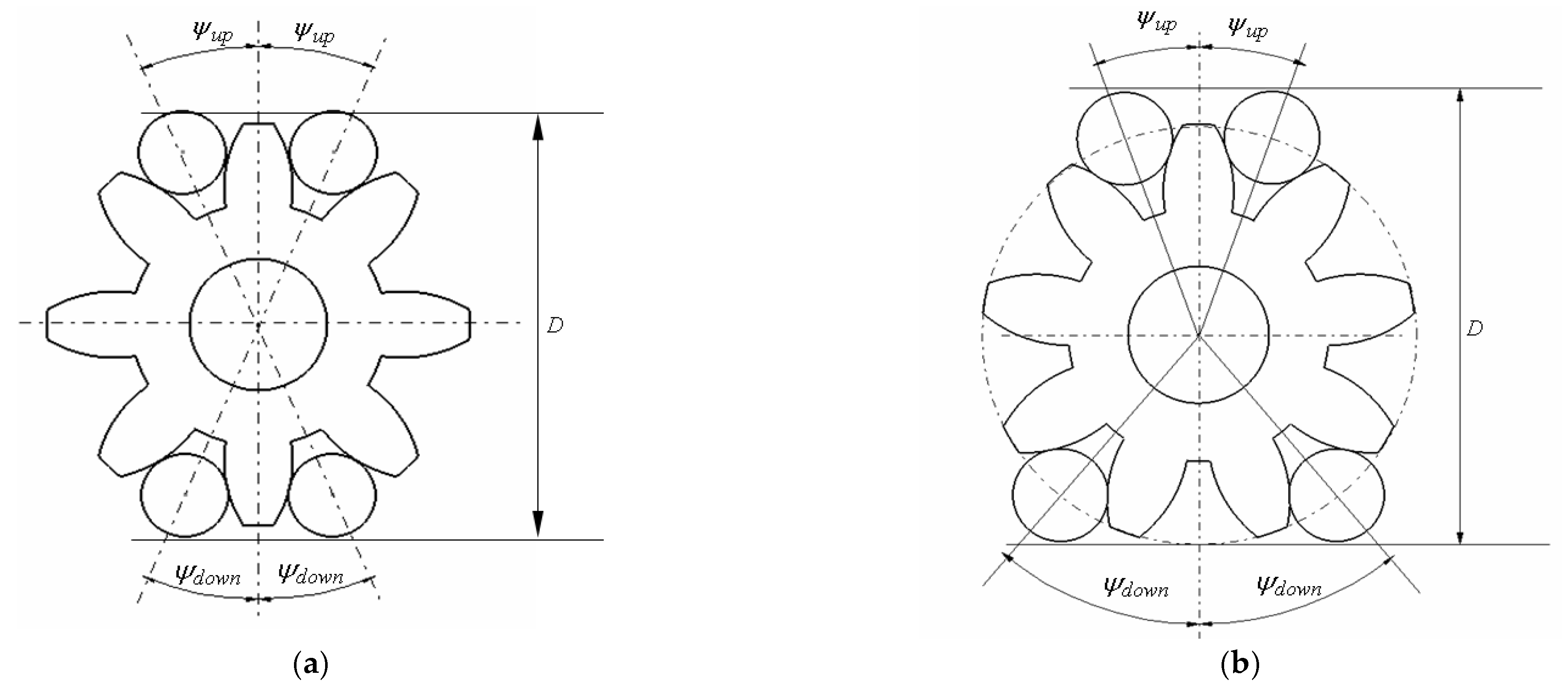
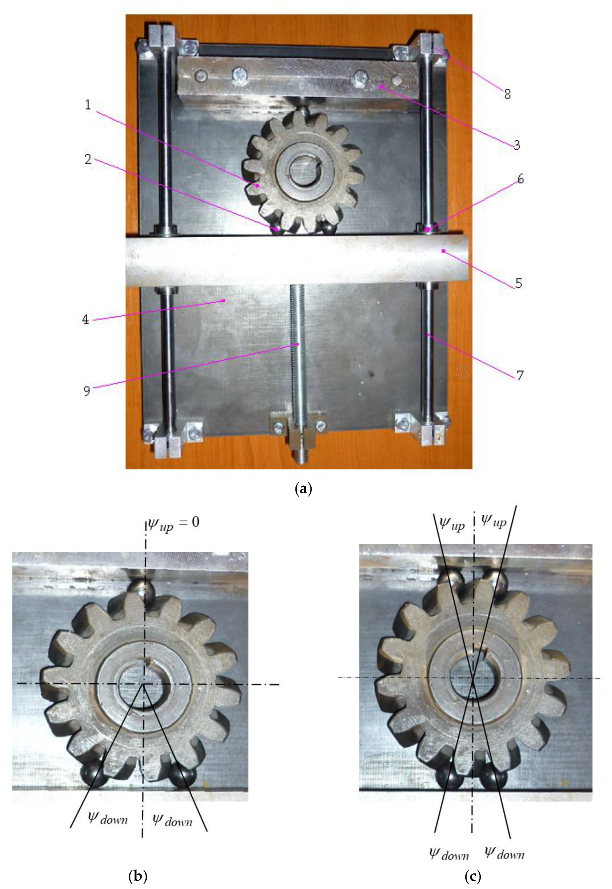
2.3. Method and Device for Finding the Characteristic Parameters of the Helical Gears with Involute Teeth

2.3.1. The Procedure for Finding the Characteristic Parameters of a Helical Gear with Involute Teeth

In a recent work, the authors proposed a quick and cost-effective technique, along with the associated device, to accurately determine the three geometric characteristics of an involute toothed spur gear: the number of teeth z , the module m , and the profile shift coefficient x . The method is based on the manner of precision control of the spur gear with involute teeth using the measurement over pins. Two main disadvantages are obvious for the method of over pins measurement:
  • The mechanical system formed by the measuring instrument, the two pins, and the measured wheel is not steady, and the distance to be measured is accepted as the maximum value of the distance between the two pins;
  • The application of the method varies depending on whether the number of teeth is odd or even.
The method proposed in [25] eliminates these drawbacks by employing a number of three or four pins, placed symmetrically with respect to the measuring direction, Figure 9a (even teeth number) and Figure 9b (odd teeth number).
As a fundamental premise, the method involves experimentally determining the dimension over pins by utilizing a specifically designed device and expressing this dimension in terms of the gear’s three primary geometric features. Finally, an equation of two unknowns, the module m and the profile shift coefficient x , is obtained:
i n v acos m z cos α 0 2 ( D d R ) ( c o s ψ u p + cos ψ d o w n ) = i n v α 0 π 2 z + 2 x z tan α 0 + d R m z α 0
Therefore, two equations are necessary to find the two parameters m and x . To overcome this, it is essential to note that the dimensions of the wheel do not undergo significant change for the typical values of the profile shift coefficient:
0.5 < x < 0.5
So, by replacing x = 0 in Equation (43), the following equation of the unknown module m is obtained:
i n v acos m z cos α 0 2 ( D d R ) ( c o s ψ u p + cos ψ d o w n ) = i n v α 0 π 2 z + d R m z α 0
This equation can be solved simply. Next, knowing that the module m takes standard values, the actual module of the gear is chosen as the standard value m s t d , closest to the solution of Equation (45). Now, the adopted standard value of the module m s t d is replaced in Equation (43) and an equation from which the profile shift coefficient x is found is obtained:
i n v acos m std z cos α 0 2 ( D d R ) ( cos ψ u p + cos ψ d o w n ) = i n v α 0 π 2 z + 2 x z tan α 0 + d R m s t d z α 0

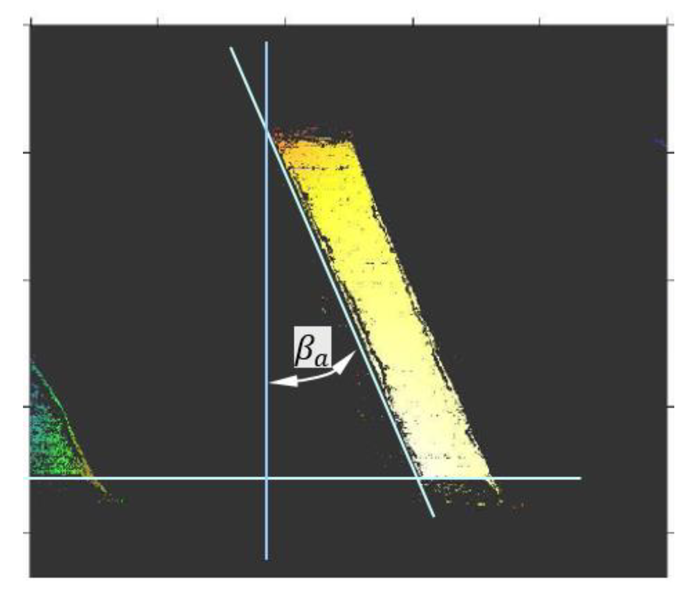
2.3.2. Alternative Method for the Helical Gears

The methodology outlined above is not applicable to involute helical gears. The main reason for this is the difficulty of employing pins or rollers with this type of gear. As illustrated in Figure 10, the axes of the two pins making contact with the tooth flanks are not coplanar, making this approach impractical.
This can be overcome by using ball bearings spheres, keeping in mind that these balls should be in contact with the flanks of the teeth and with another frontal surface. The motivation behind this approach is to ensure that all the sphere centres are situated within the same frontal plane, as demonstrated in Figure 11.
The geometry of the wheel is characterised by the number of teeth z , the module m in the normal section, the normal profile shift coefficient x , and the helix angle of the teeth of the base rack β 0 . The gearing is studied in the frontal section, and the profile is also an involute, characterised by the number of teeth z , the frontal module m t , and the frontal profile shift coefficient x t .
Considering the relation (25) and the fact that the angle β 0 may take any value, it results that in the frontal section, the value of the module is not standard and the methodology applied for the spur gears is not effective. Therefore, in this case, the conditions imposed upon the coordinates of the contact points are used.
In Figure 12, a frontal section is presented, which contains the centre of a ball of radius r B which makes contact with the boundary flanks at points Y and Y . The normal at the contact point is tangent to the base circle in the T y point. The Y points are placed on a circle characterised by the pressure angle α y t of the involute generated using the base circle of radius r b . The pitch circle passes through points D .
Applying the involute properties, one can write
a r c Y Y = r y φ y t = 1 2 m z cos α 0 t cos α y t [ φ 0 t + 2 ( θ y t θ 0 t ) ] = 1 2 m z cos α 0 t cos α y t e d d / 2 + 2 ( i n v α y t i n v α 0 t ) = m z cos α 0 t cos α y t π 2 2 x t tan α 0 t z + ( i n v α y t i n v α 0 t ) = m z cos α 0 t cos α y t π 2 z 2 x t tan α 0 t z + ( i n v α y t i n v α 0 t )
where φ y represents the arc of the space width on the circle C y and φ 0 t is the arc of the space width on the pitch circle. From the above relation, one can obtain
φ y t = a r c Y Y r y = m z cos α 0 t cos α y t π 2 z 2 x t tan α 0 t z + ( i n v α y t i n v α 0 t ) 1 2 m z cos α 0 t cos α y t = 2 π 2 z 2 x t tan α 0 t z + ( i n v α y t i n v α 0 t )
Next, one can obtain
T Y O T Y = φ y t + 2 α y t = 2 π 2 z 2 x t tan α 0 t z + ( i n v α y t i n v α 0 t ) + 2 α y t = 2 π 2 z 2 x t tan α 0 t z + ( i n v α y t + α y t i n v α 0 t ) = 2 π 2 z 2 x t tan α 0 t z + tan α y t i n v α 0 t
The angles T Y O B T Y and T Y O T Y are supplementary:
T y O B T y = π 2 π 2 z 2 x t tan α 0 t z + tan α y t i n v α 0 t
The length of the cord Y Y can be expressed in two ways:
r B sin 1 2 π 2 π 2 z 2 x t tan α 0 t z + tan α y t i n v α 0 t = r y sin 1 2 2 π 2 z 2 x t tan α 0 t z + ( i n v α y t i n v α 0 t )
And from here, the following equation is obtained:
r B cos π 2 z 2 x t tan α 0 t z + tan α y t i n v α 0 t = 1 2 m z cos α 0 t cos α y t sin π 2 z 2 x t tan α 0 t z + ( i n v α y t i n v α 0 t )
Additionally, the radius of the centre of the ball can be found:
Y B = r B cos 1 2 π 2 π 2 z 2 x t tan α 0 t z + tan α y t i n v α 0 t + r y cos 1 2 2 π 2 z 2 x t tan α 0 t z + ( i n v α y t i n v α 0 t )
From here, the following is obtained:
Y B = r B sin π 2 z 2 x t tan α 0 t z + tan α y t i n v α 0 t + 1 2 m z cos α 0 t cos α y t cos π 2 z 2 x t tan α 0 t z + ( i n v α y t i n v α 0 t )
Figure 13 shows that the measured dimension over balls D using the proposed device can be expressed as
D = Y B cos ψ u p + Y B cos ψ d o w n + 2 r B
where Y B is the radius of the circle where the centres of the balls (of radii r B ) are positioned in the space between teeth, contacting both flanks of the teeth. As previously stated, the balls are positioned symmetrically with respect to the diameter parallel to the direction of measurement. From relation (55), the following is obtained:
Y B = D 2 r B cos ψ u p + cos ψ d o w n
The relations (54) and (56) result in the equation:
r B sin π 2 z 2 x t tan α 0 t z + tan α y t i n v α 0 t + 1 2 m z cos α 0 t cos α y t cos π 2 z 2 x t tan α 0 t z + ( i n v α y t i n v α 0 t ) = D 2 r B cos ψ u p + cos ψ d o w n
Now, considering the Equations (52) and (57), the following system is obtained:
r B cos π 2 z 2 x t tan α 0 t z + tan α y t i n v α 0 t = 1 2 m z cos α 0 t cos α y t sin π 2 z 2 x t tan α 0 t z + ( i n v α y t i n v α 0 t ) r B sin π 2 z 2 x t tan α 0 t z + tan α y t i n v α 0 t + 1 2 m z cos α 0 t cos α y t cos π 2 z 2 x t tan α 0 t z + ( i n v α y t i n v α 0 t ) = Y B
The unknowns of the system are
  • the frontal module m t ;
  • the frontal pressure angle α y t on the circle passing through the contact points;
  • the frontal profile shift coefficient of the gear x t ;
  • The frontal pressure angle α 0 t on the pitch cylinder of the gear.
Considering that the method is applied using two sets of balls of radii r B 1 and r B 2 positioned at the angles ψ d o w n 1 , ψ u p 1 , ψ d o w n 2 , and ψ u p 2 , respectively, the system (58) written for the two cases leads to a system of four equations which, after some calculations, takes the form
m z 2 Y B 1 cos α 0 t cos asin r B 1 Y B 1 cos α y 1 t + α y 1 t = 0 r B 1 cos α y 1 t Y B 1 π 2 z 2 x t tan α 0 t z + i n v α y 1 t i n v α 0 t = 0 m z 2 Y B 2 cos α 0 t cos asin r B 2 Y B 2 cos α y 1 t + α y 2 t = 0 r B 2 cos α y 2 t Y B 2 π 2 z 2 x t tan α 0 t z + i n v α y 2 t i n v α 0 t = 0
A system of two transcendental equations (from the first and third equation of system (59) and, respectively, from the second and fourth equation) of unknowns α y 1 t and α y 2 t results in
Y B 1 cos asin r B 1 Y B 1 cos α y 1 t + α y 1 t Y B 2 cos asin r B 2 Y B 2 cos α y 2 t + α y 2 t = 0 i n v α y 1 t asin r B 1 Y B 1 cos α y 1 t i n v α y 2 t + asin r B 2 Y B 2 cos α y 2 t = 0
The two unknowns α y 1 t and α y 2 t are found via a numerical method. After the two pressure angles are found, two equations of system (59) are considered (either the first two, or the last two equations). We consider here the first two equations of system (59) and with the relations (25), (33), and (39) between the geometrical parameters from the normal and frontal section; the next system of equations results in
m t z 2 Y B 1 cos α 0 t cos asin r B 1 Y B 1 cos α y 1 t + α y 1 t = 0 r B 1 cos α y 1 t Y B 1 π 2 z 2 x t tan α 0 t z + i n v α y 1 t i n v α 0 t = 0
Now, we recall Equations (25), (39), and (54) and have
m cos β 0 2 Y B 1 z cos atan tan α 0 cos β 0 cos asin r B 1 Y B 1 cos α y 1 t + α y 1 t = 0 r B 1 cos α y 1 t Y B 1 π 2 z 2 x cos β 0 tan α 0 cos β 0 z + i n v α y 1 t i n v atan tan α 0 cos β 0 = 0
The resulting system (62) has three unknowns:
  • The normal module m , which takes standard values;
  • The helix angle of the flank β 0 on the pitch cylinder of the wheel;
  • The normal profile shift coefficient x of the wheel.
A further equation is needed to solve the system. To this end, we accept the hypothesis (justified in Appendix A) that the helix angle β a of the flank on the addendum cylinder does not differ substantially from the helix angle from the pitch cylinder β 0 . This remark is extremely important because the slant of the tooth on the addendum cylinder can be measured relatively easily, since the addendum surface exists physically while the pitch surface is fictive. Supposing that the inclination angle of the tooth on the addendum cylinder β a is found, this value is replaced into the first equation of system (62):
m cos β a 2 Y B 1 z cos atan tan α 0 cos β a cos asin r B 1 Y B 1 cos α y 1 t + α y 1 t = 0
and then, the equation is solved with respect to m :
m = 2 Y B 1 cos a s i n ( r B 1 Y B 1 cos α y 1 t ) cos β a z 1 + tan 2 α 0 cos 2 β a
The closest standard value is adopted for the normal module:
m n = m n s t d
and using this value, it is replaced in Equation (63) and then the equation is solved with respect to the angle β 0 :
β 0 = acos z 2 m n s t d 2 2 cos a s i n ( r B 1 Y B 1 cos α y 1 t ) Y B 1 2 tan 2 α 0
Now, the helix angle on the pitch cylinder is known and this value is replaced in the second Equation (62), obtaining an equation of unknown x , the normal profile shift coefficient. The solution is
x = z 2 tan α 0 π 2 z + i n v α y 1 t i n v atan tan α 0 cos β 0 a s i n ( r B 1 Y B 1 cos α y 1 t )

3. Exemplification of the Methodology

The methodology we use with the measuring device is as follows: For the teethed wheel to be measured as 1, the axis of measurement is found; it is defined by two spaces between teeth or by two teeth diametrically opposite. For an odd number of teeth, the axis is defined by a space and a tooth placed diametrically opposite. Then, two pairs of balls 2 are introduced in the spaces placed symmetrically with respect to the measuring axis. One of the pairs of balls is brought into contact with the surface of the fixed prism 3, which is assembled by screws on the base plate 4. Next, the mobile prism 5 is carefully moved until its surface meets the second pair of balls. In order to diminish the risk of locking the mobile prism, it has ball bushings which ensure a smooth and noiseless motion along the guiding rods 7, fixed on the base plate by the support parts 8. When all the balls have made firm contact with the prisms, the assembly is fixed using the screw 9. Then, the distance D is measured and the angles ψ u p and ψ d o w n are calculated. The methodology is repeated for another configuration of the balls, symmetrically placed with respect to the measuring axis. Next, Table 1 is completed and the relations presented in the paper are applied.
The method is exemplified by applying it to an actual teethed wheel with the number of teeth z = 14 . The device presented in [25] is used, but the pins were replaced by balls of radii r B 1 and r B 2 ; for the two sets of balls (Figure 14), the dimension over balls D 1 and D 2 were measured. The values of the involved parameters for two values of the radii at which the balls’ centres are positioned— the radii of balls r B 1 and r B 2 , distances D 1 and D 2 , positioning angles ψ u p and ψ d o w n —and the values resulting from the calculation with relations (55) and (56) are presented in Table 1.
With these values, a system of transcendental Equation (60) is obtained which is solved using the Newton–Raphson method. The convergence of the solutions of the system as function of the number of iterations is presented in Figure 15. It can be observed that the method is rapidly convergent and conducts to the values of the pressure angles of the involute profile on the circles where the ball–tooth flank contact points are placed.
In order to find the helix angle β a of the teeth on the addendum cylinder, two methods were used: first, the wheel was scanned using a laser profilometer (Nanofocus μscan), shown in Figure 16, and then, a photo of the wheel was taken from the side, shown in Figure 17. The helices from the addendum cylinders and the helix angles with respect to the axis of the gear are identified in both images.
By comparing the measured angles from the two figures, equal values β a = 2 3 o were found. Taking a photo is a much simpler method compared to scanning. Now, with found values β a and α y 1 t one can apply Equation (64) and the normal module of the gear results in m = 4.949 . Next, the standard normal module is adopted m s t d = 5 ; angle β 0 is obtained by applying relation (65), β 0 = 21.34 4 o , and next, by applying relation (66), the profile shift coefficient is found x = 0.105 . Subsequently, it is proven that the values α y 1 t , α y 2 t , m s t d , β 0 , and x verify the system of Equation (59).

4. Conclusions

The paper is a progression of a recent work of the authors [25] concerning the accurate determination of the three basic parameters of an actual spur gear with involute teeth (number of teeth, module, profile shift coefficient) where an expedited method and the related measuring device are presented.
The current study introduces a rapid, straightforward, and inexpensive approach for identifying the basic parameters of helical gears. In addition to the three parameters mentioned above, for helical teeth, another basic parameter occurs: the angle of tooth inclination—the helix angle on the pitch cylinder.
For helical gears, due to the inclination of the teeth, the method proposed for the spur gear is inapplicable. Therefore, the rolling bodies introduced between the teeth of the gear to be measured are no longer pins, but balls; thus, the contact with the surfaces of the measuring device is of the point type.
Another consequence of the slanted tooth of the gear is the existence of two profiles: a normal one, where the module has standard values identical to the values of the module of the basic rack, and a transverse one, defined in a section normal to the axis of the wheel. The entire gearing can be studied in the frontal section, similarly to a spur gear, but without the necessity of a standard module. Concerning the control method, the condition that the centre of the ball occupies an imposed position is required. Additionally, we have the condition of positions of the contact points between the balls and the flanks of the teeth. Two sets of balls of different sizes are necessary for a measurement, and the selection of the radii of the balls is made in a manner to ensure the contact point with the flanks on the involute surface of the flank.
Subsequent to the measurements, a system of four equations is obtained, with five unknowns: the pressure angles of the involute profile on the circles passing through the contact point ball–flank, the normal module, the normal profile shift coefficient, and the helix angle on the pitch cylinder.
The research demonstrates that for gears with a typical number of teeth and profile shift coefficient, the helix angle of the tooth on the pitch cylinder can be approximated to be the angle from the top land, which can be conveniently determined through experimental measurements. Therefore, the system becomes compatible and allows for finding, with some approximation, all the basic parameters of the gear. Then, the normal module is adopted as the closest standard value compared to the solution obtained from the system. Further, by employing the standard value for the module, the system of four equations is resolved, leading to the precise determination of the fundamental parameters: the profile’s pressure angle at the points of ball–tooth contact, the helix angle on the pitch cylinder, and the normal profile shift coefficient.
The method is then exemplified for a concrete situation.

Author Contributions

Conceptualization, SA. and I.D.; methodology, S.A., F.-C.C. and C.B.; software, S.A. and I.-C.R.; validation, I.-C.R. and I.T.; writing—original draft preparation, F.-C.C. and C.B.; writing—review and editing, I.-C.R. and I.T.; visualization, I.T; supervision, I.D., C.B. and F.-C.C. All authors have read and agreed to the published version of the manuscript.

Funding

This research received no external funding.

Data Availability Statement

Data are contained within the article.

Conflicts of Interest

The authors declare no conflicts of interest.

Appendix A

The appendix is meant to justify the assumption that for gears with z > 10, the helix angle from the addendum cylinder is practically the same as the helix angle from the pitch cylinder.
Next, it is considered a helical gear having the following parameters: number of teeth z ; normal module m ; and normal coefficient of profile shift m . The helix angle on the addendum cylinder β 0 is
β a = atan d a d tan β 0
where d is the pitch diameter:
d = z m c o s β 0
and d a is the addendum diameter:
d a = d + 2 ( h a 0 + x ) m = m z cos β 0 + 2 h a 0 + 2 x
where h a 0 = 1 . Then, the following equation is obtained:
β a = atan m z cos β 0 + 2 h a 0 + 2 x z m cos β 0 tan β 0 = atan z cos β 0 + 2 h a 0 + 2 x z sin β 0
The number of teeth and the profile shift coefficient affect the helix angle on the addendum cylinder. These aspects are presented in Figure A1 and Figure A2 for z = 10 ÷ 80 .
Figure A1. The helix angle on the addendum cylinder versus the number of teeth.
Applsci 14 02043 g0a1
Figure A2. The helix angle on the addendum cylinder versus the profile shift coefficient.
Applsci 14 02043 g0a2

References

  1. Freudenstein, F. An Analytical Approach to the Design of Four-Link Mechanisms. ASME Trans. 1954, 76, 483–489. [Google Scholar] [CrossRef]
  2. Flores, P.; Ambrósio, J.; Pimenta Claro, J.C.; Lankarani, H.M. Kinematics and Dynamics of Multibody Systems with Imperfect Joints; Springer: Berlin/Heidelberg, Germany, 2008; pp. 23–45. [Google Scholar]
  3. Seherr-Thoss, H.C.; Schmelz, F.; Aucktor, E. Universal Joints and Driveshafts: Analysis, Design, Applications, 2nd ed.; Springer: Berlin/Heidelberg, Germany, 2006; pp. 53–79, 109–245. [Google Scholar]
  4. Dudiţă, F. Mobile Homokinetic Couplings; Tehnică: Bucharest, Romania, 1974; pp. 209–225. (In Romanian) [Google Scholar]
  5. Innocenti, C. The instantaneous transmission ratio of a driveshaft composed of a tripod joint and a fixed constant velocity joint. Mech. Mach. Theory 2023, 189, 105430. [Google Scholar] [CrossRef]
  6. Qiu, Y.; Shangguan, W.B.; Lou, Y. Kinematic analysis of the double roller tripod joint. J. Multi-Body Dyn. 2020, 234, 147–160. [Google Scholar] [CrossRef]
  7. Pennestrì, E.; Rossi, V.; Salvini, P.; Valentini, P.P.; Pulvirenti, F. Review and kinematics of Rzeppa-type homokinetic joints with straight crossed tracks. Mech. Mach. Theory 2015, 90, 142–161. [Google Scholar] [CrossRef]
  8. Alaci, S.; Doroftei, I.; Ciornei, F.-C.; Romanu, I.-C.; Doroftei, I.-A.; Ciornei, M.-C. A new RP1PR type coupling for shafts with crossed axes. Mathematics 2023, 11, 2025. [Google Scholar] [CrossRef]
  9. Radzevich, S.P. Theory of Gearing. Kinematics, Geometry and Synthesis, 3rd ed.; CRC Press: Boca Raton, FL, USA, 2023; pp. 79–107. [Google Scholar]
  10. Phillips, J. General Spatial Involute Gearing; Springer: Berlin/Heidelberg, Germany, 2003; pp. 41–61. [Google Scholar]
  11. Reuleaux, F. The Kinematics of Machinery: Outlines of a Theory of Machines; Dover Publications: Mineola, NY, USA, 2012; pp. 121–157. [Google Scholar]
  12. Alaci, S.; Ciornei, F.-C.; Doroftei, I. The conjugate profile of the circular teeth of a spur gear. Part II: Problem solution. IOP MSE 2020, 997, 012068. [Google Scholar] [CrossRef]
  13. Boral, P.; Gołębski, R.; Kralikova, R. Technological Aspects of Manufacturing and Control of Gears—Review. Materials 2023, 16, 7453. [Google Scholar] [CrossRef] [PubMed]
  14. Ling, M.; Ling, S.; Li, X.; Shi, Z.; Wang, L. Effect on the measurement for gear involute profile caused by the error of probe position. Meas. Sci. Technol. 2022, 33, 115013. [Google Scholar] [CrossRef]
  15. Palermo, A.; Britte, L.; Janssens, K.; Mundo, D.; Desmet, W. The Measurement of Gear Transmission Error as an NVH Indicator: Theoretical Discussion and Industrial Application via Low-Cost Digital Encoders to an All-Electric Vehicle Gearbox. Mech. Syst. Signal Process. 2018, 110, 368–389. [Google Scholar] [CrossRef]
  16. Yuan, B.; Chang, S.; Liu, G.; Wu, L.Y. Quasi-Static and Dynamic Behaviors of Helical Gear System with Manufacturing Errors. Chin. J. Mech. Eng. 2018, 31, 30. [Google Scholar] [CrossRef]
  17. Colbourne, J.R. The Geometry of Involute Gears—Softcover Reprint of the Original, 1st ed.; Springer: New York, NY, USA, 1987; pp. 191–200. ISBN 978-1-4612-4764-7. [Google Scholar]
  18. Jalaska, D. Gears and Gear Drives; John Wiley & Sons Ltd.: West Sussex, UK, 2012; pp. 106–155. ISBN 9781119941309. [Google Scholar]
  19. Jantzen, S.; Neugebauer, M.; Meeß, R.; Wolpert, C.; Dietzel, A.; Stein, M.; Kniel, K. Novel measurement standard for internal involute microgears with modules down to 0.1 mm. Meas. Sci. Technol. 2018, 29, 125012. [Google Scholar] [CrossRef]
  20. Härtig, F.; Stein, M. 3D involute gear evaluation—Part I: Workpiece coordinates. Measurement 2019, 134, 569–573. [Google Scholar] [CrossRef]
  21. Stein, M.; Härtig, F. 3D involute gear evaluation—Part II: Deviations—Basic algorithms for modern software validation. Meas. Sci. Technol. 2022, 33, 125003. [Google Scholar] [CrossRef]
  22. Guo, X.; Shi, Z.; Yu, B.; Zhao, B.; Li, K.; Sun, Y. 3D measurement of gears based on a line structured light sensor. Precis. Eng. 2022, 61, 160–169. [Google Scholar] [CrossRef]
  23. Stein, M.; Keller, F.; Przyklenk, A. A unified theory for 3d gear and thread metrology. Appl. Sci. 2021, 11, 7611. [Google Scholar] [CrossRef]
  24. Bolotovskaia, T.F.; Bolotovski, I.A.; Smirnov, V.E. Guide for Gear Profile Shifting; Institutul de Documentare Tehnică: Bucharest, Romania, 1964. (In Romanian) [Google Scholar]
  25. Alaci, S.; Ciornei, F.-C.; Romanu, I.-C.; Doroftei, I.; Bujoreanu, C.; Tamașag, I. A New Direct and Inexpensive Method and the Associated Device for the Inspection of Spur Gears. Machines 2023, 11, 1046. [Google Scholar] [CrossRef]
Figure 1. The involute of the circle: generation and properties.
Applsci 14 02043 g001
Figure 2. The basic rack with straight teeth.
Applsci 14 02043 g002
Figure 3. The pitch straight line of the rack rolls over the pitch circle of the gear; the profile shift definition.
Applsci 14 02043 g003
Figure 4. The effect of number of teeth z and of the profile shift coefficient x upon the shape of the wheel machined with tools of rack type.
Applsci 14 02043 g004
Figure 5. Defining the flank for a helical spur gear with involute teeth.
Applsci 14 02043 g005
Figure 6. Establishing the angle of the tooth helix on an arbitrary cylinder.
Applsci 14 02043 g006
Figure 7. The basic rack with helical teeth.
Applsci 14 02043 g007
Figure 8. Sections through basic rack with helical teeth: a section with the base plane (hatched), a section normal to the tooth (n-n), and a frontal section (t-t).
Applsci 14 02043 g008
Figure 9. The proposed method for finding the characteristic parameters of a spur gear with involute teeth: (a) gear with even number of teeth, when the direction of measurement passes through two teeth or two spaces; (b) gear with odd number of teeth, when the direction of measurement passes through a tooth and a space.
Applsci 14 02043 g009
Figure 10. The axes of the pins are not coplanar.
Applsci 14 02043 g010
Figure 11. Schematics for the device used for involute helical gears.
Applsci 14 02043 g011
Figure 12. Finding the coordinates of the contact points.
Applsci 14 02043 g012
Figure 13. The dimension over balls for the proposed method.
Applsci 14 02043 g013
Figure 14. (a) The experimental device and the two sets of balls. Balls’ positions for the measurements: (b) ψ u p = 2 π / z , ψ d o w n = 0 ; (c) ψ u p = ψ d o w n = π / z .
Applsci 14 02043 g014
Figure 15. The fast convergence of the Newton–Raphson method applied for finding the pressure angles α y 1 and α y 2 on the circles of the contact points.
Applsci 14 02043 g015
Figure 16. The helix angle of the tooth β a on the addendum cylinder, obtained via lateral scan.
Applsci 14 02043 g016
Figure 17. The helix angle of the tooth on the addendum cylinder, measured on a lateral photo.
Applsci 14 02043 g017
Table 1. Measurements results.
r B
[mm]
ψ u p
[deg]
ψ d o w n
[deg]
D
[mm]
Y B
[mm]
entry 1 5.760 2 π / z 0 91.27 41.952
entry 2 4.75 π / z π / z 87.51 40.008
Disclaimer/Publisher’s Note: The statements, opinions and data contained in all publications are solely those of the individual author(s) and contributor(s) and not of MDPI and/or the editor(s). MDPI and/or the editor(s) disclaim responsibility for any injury to people or property resulting from any ideas, methods, instructions or products referred to in the content.

