
Research Progress on the Manufacturing of Screw-Shaped Parts in Screw Compressors


Abstract
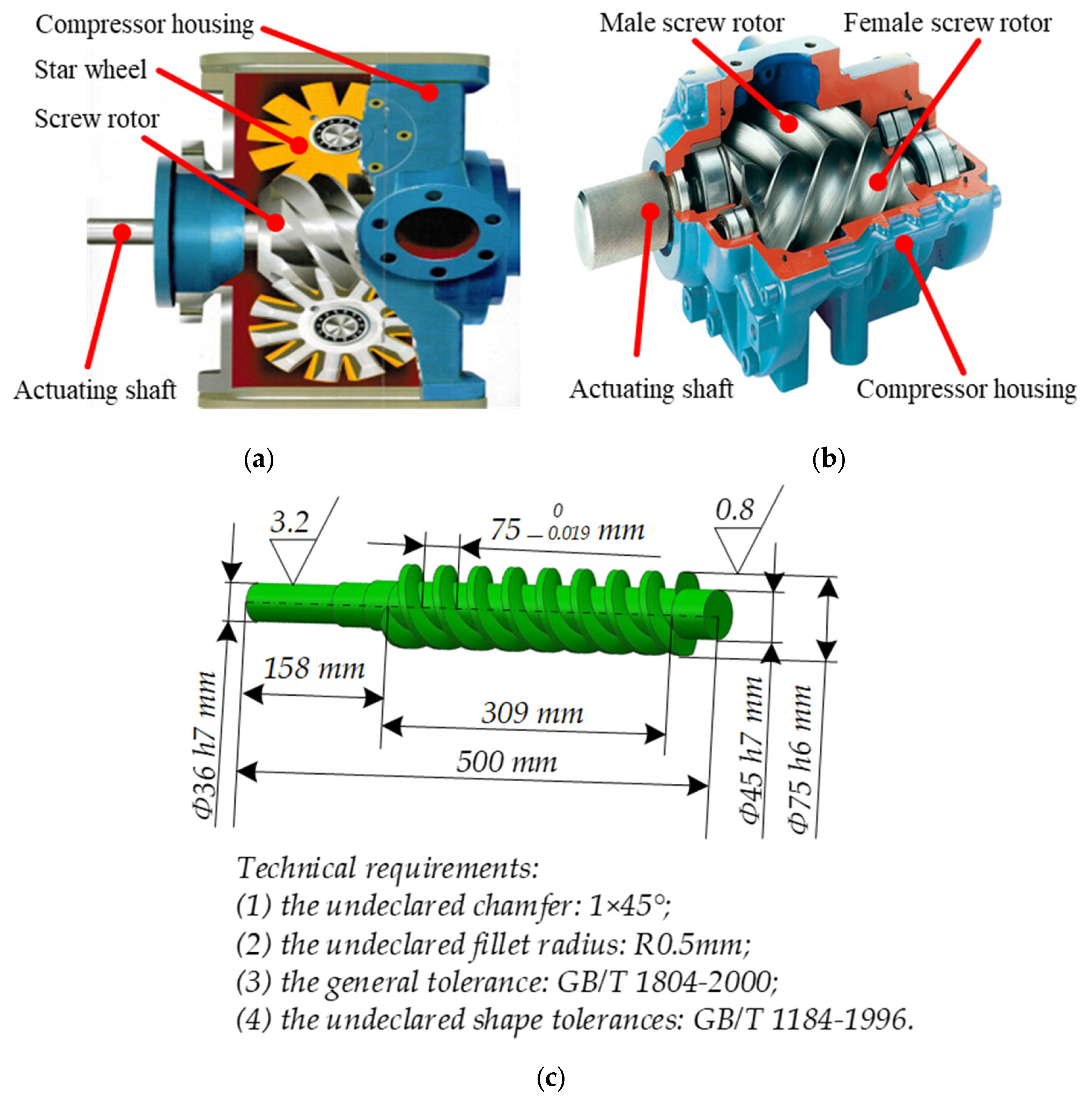
1. Introduction
2. Common Manufacturing Process for Screw-Shaped Parts
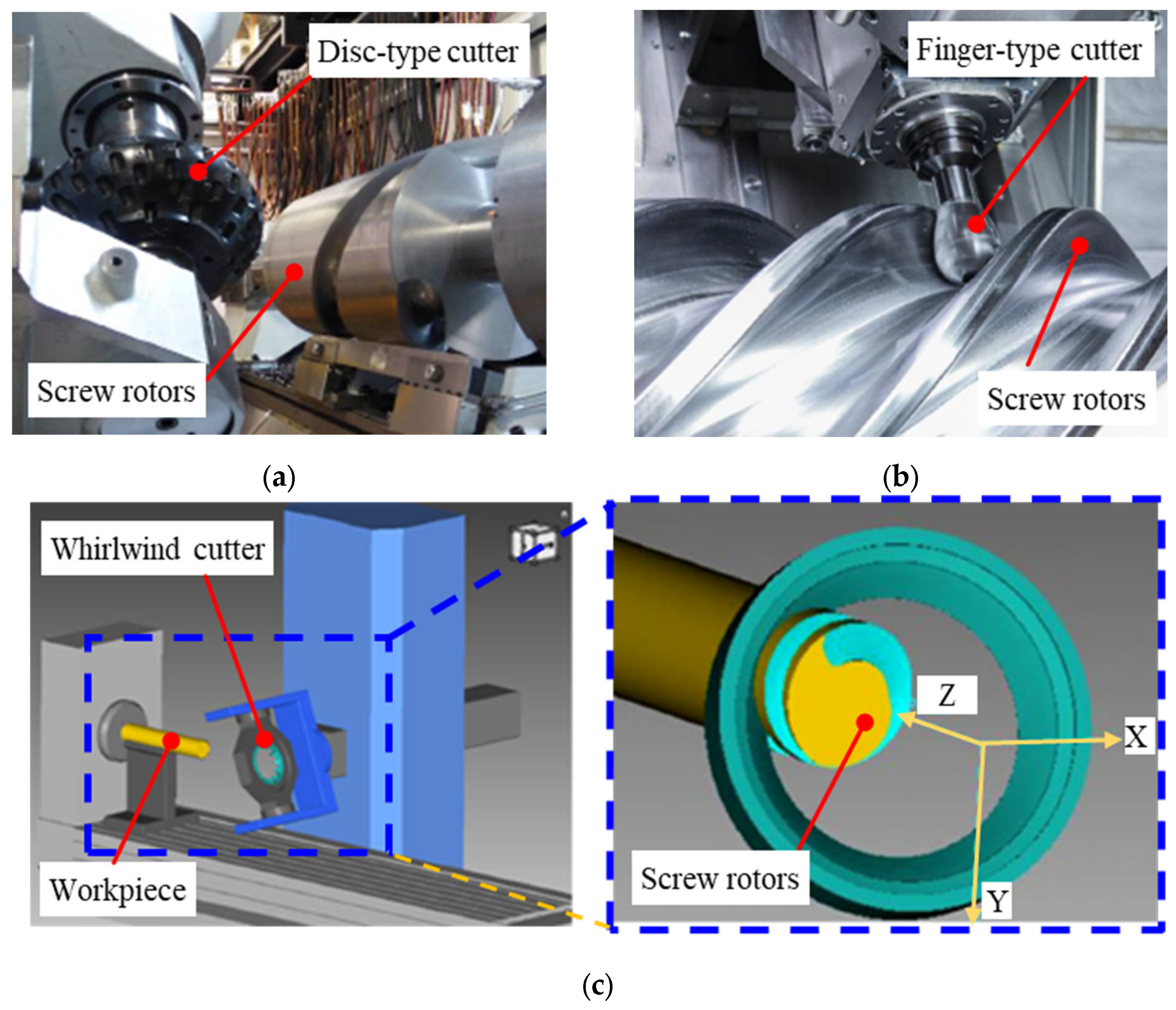
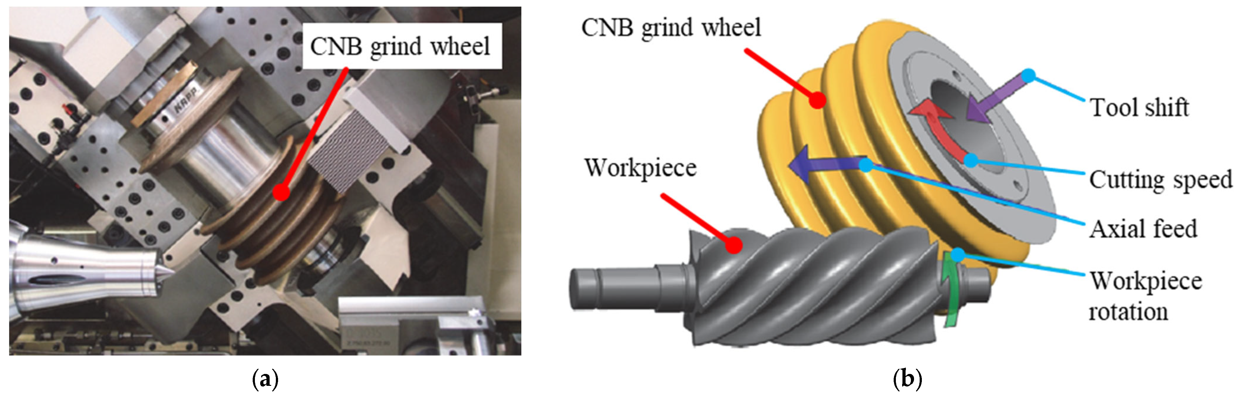
2.1. Traditional Cutting Process
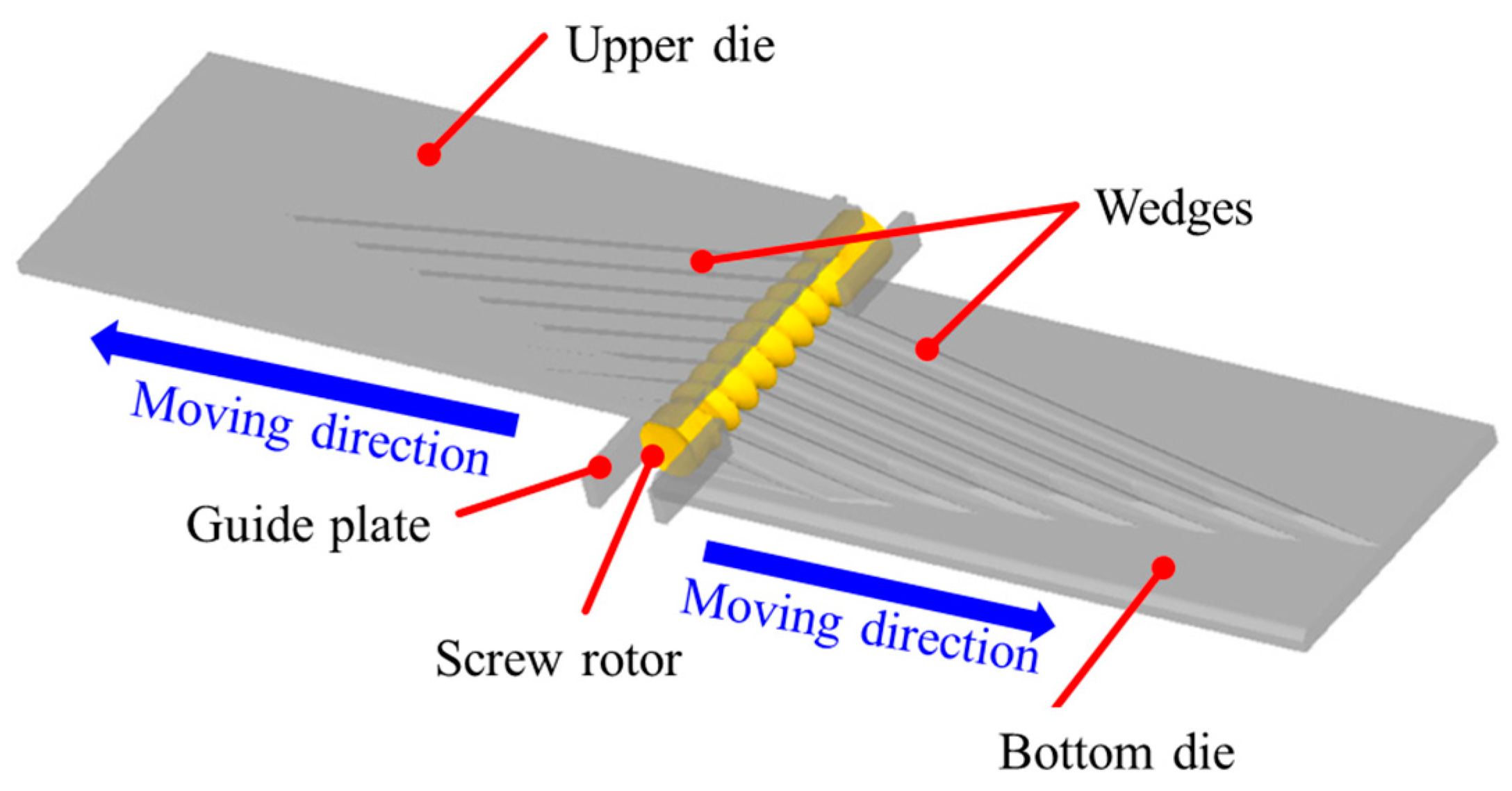
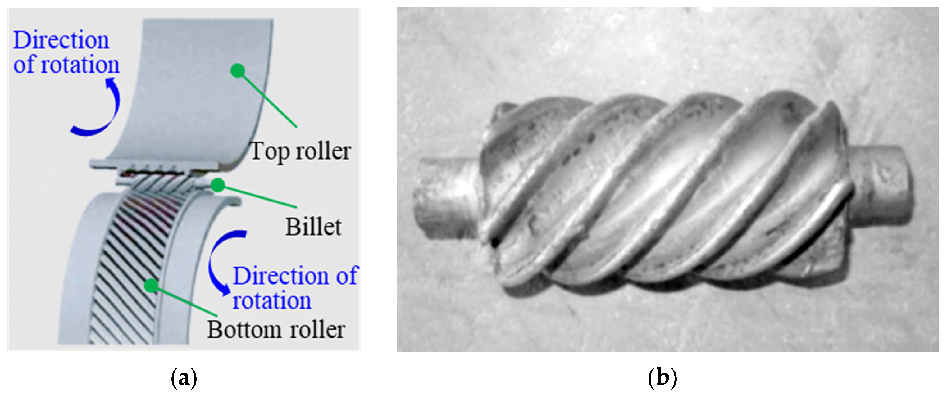
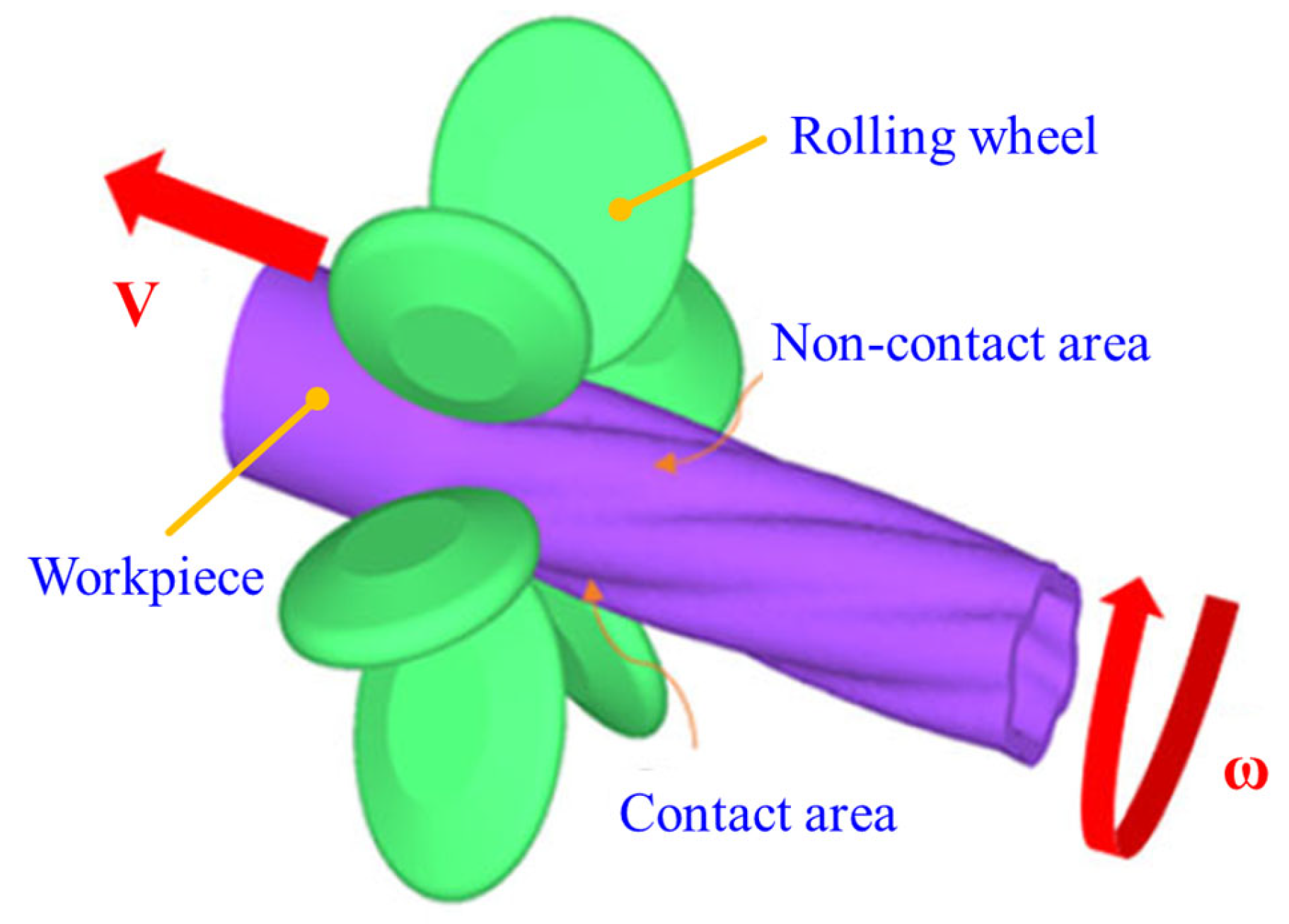
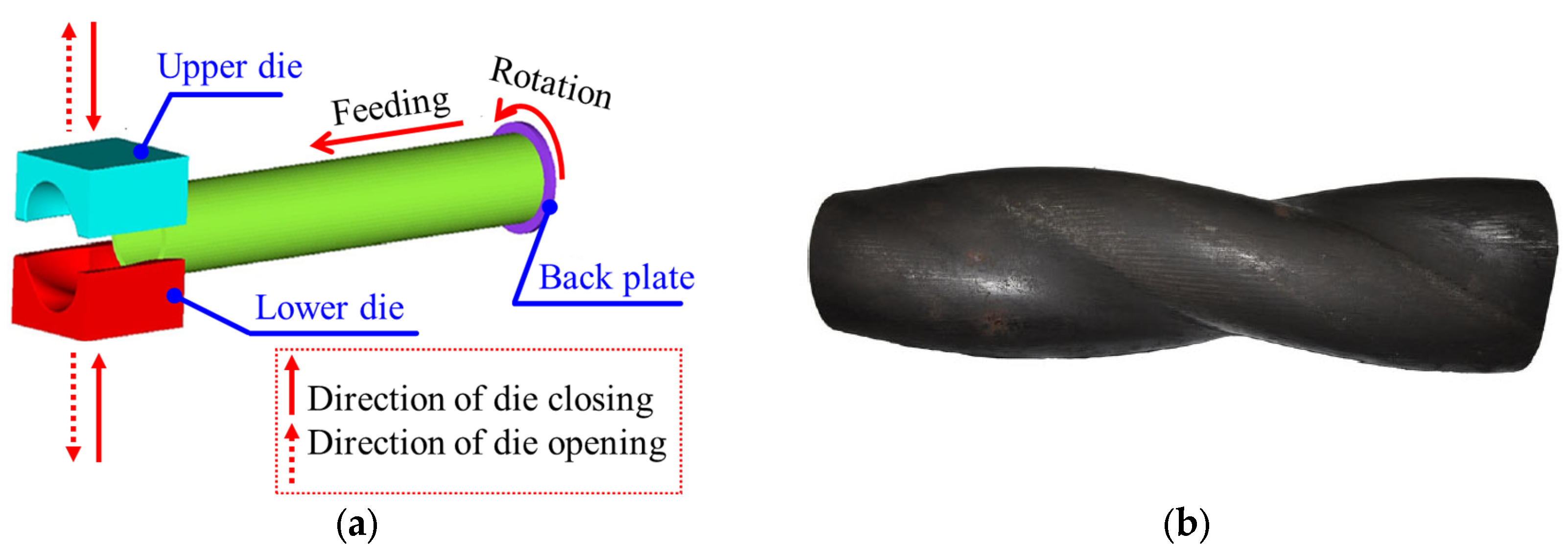
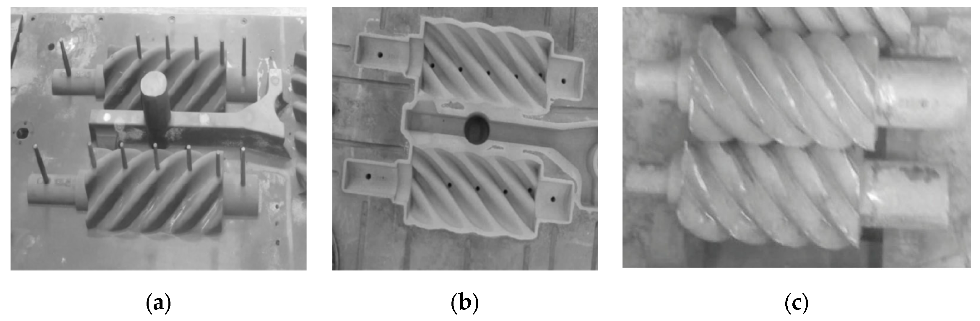
2.2. Solid Plastic Forming Process
2.3. Casting
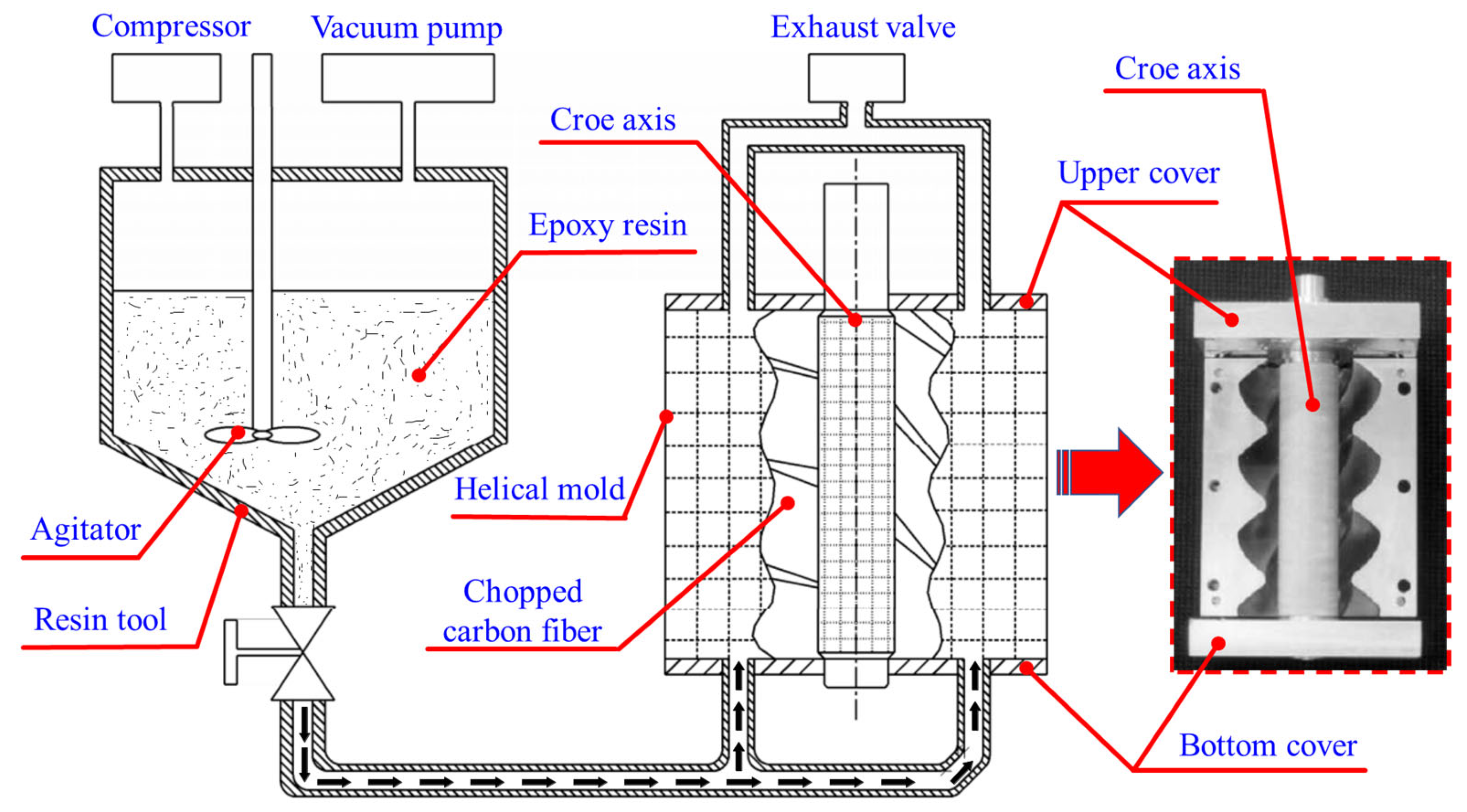
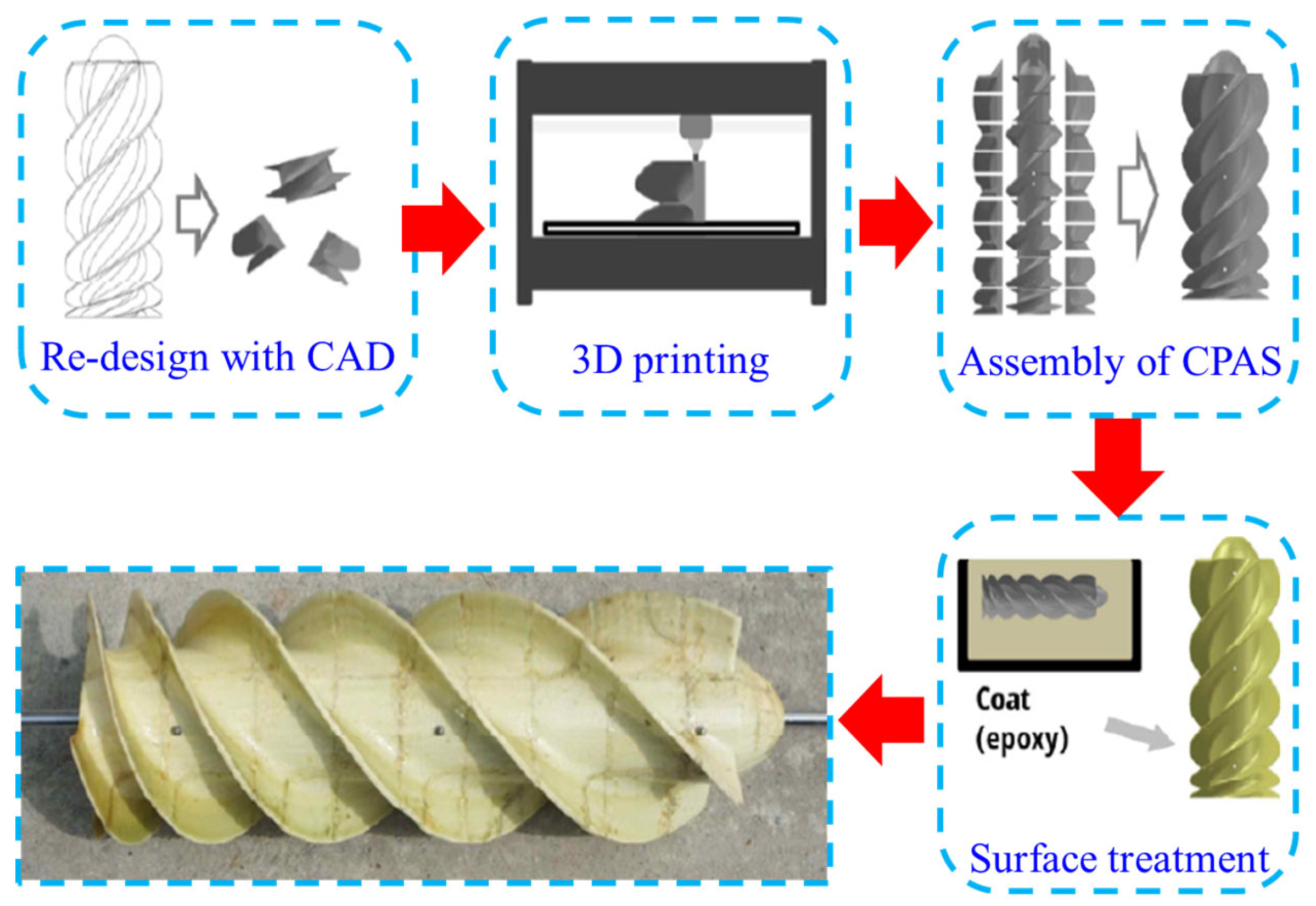
2.4. Additive Manufacturing Process
3. Summary of Common Screw Manufacturing Processes
- (1)
- In the cutting process, the material is greatly wasted. Moreover, the metal fibre is cut off, resulting in a reduction in length; thus, the mechanical property of the part reduces. The bending deformation of the workpiece is risky to form.
- (2)
- The actual production process of screw rotors needs multiple pieces of equipment, such as lathes, milling machines and grinding machines. Each process requires the replacement of tools and fixtures. The processing process is cumbersome.
- (3)
- The manufacturing cost of screw-cutting tools is high. A group of tools shall be replaced for each type of screw, where the corresponding cutter edge grinding equipment shall be provided. Consequently, the equipment investment is high.
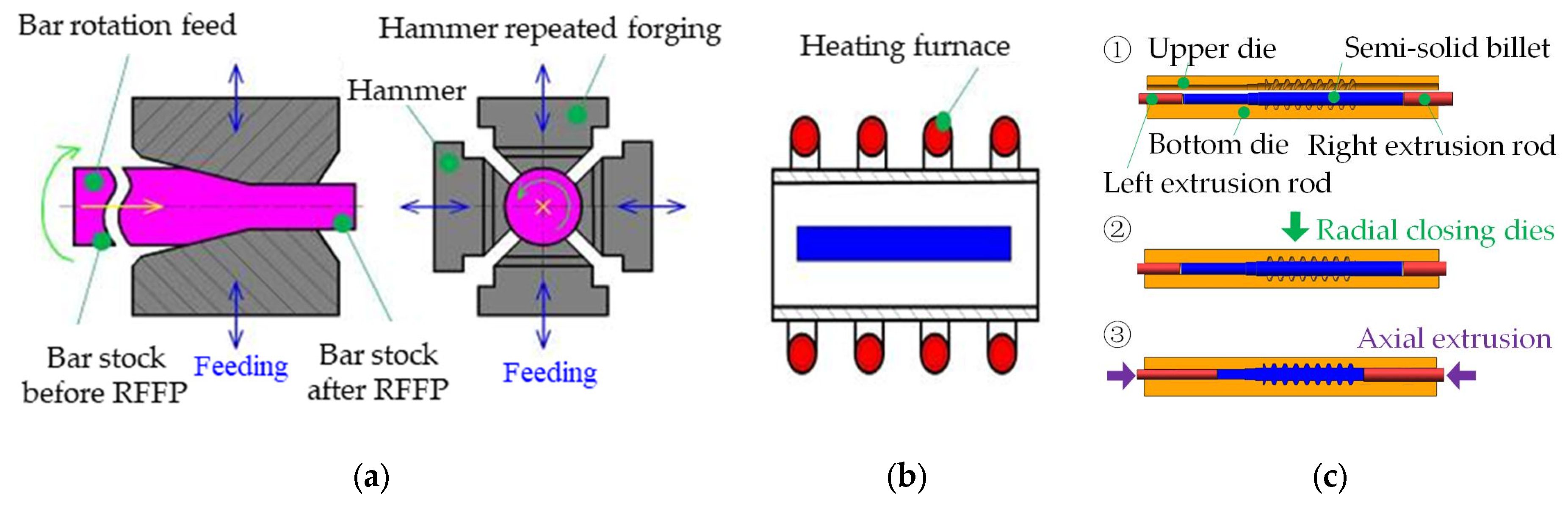
4. New Technology of Semi-Solid Closed Extrusion Forming for Screw-Shaped Parts
- (1)
- Stage I: Radial forging plastic deformation (RFFP). In this stage, the metal bar is radially forged with a suitable area reduction rate to obtain the radial-forged long-shaft metal billet; thus, a large amount of strain energy can be accumulated.
- (2)
- Stage II: Semi-solid isothermal procedure (SSIP). In the SSIP process, the long-shaft metal billet after radial forging is heated to a suitable semi-solid temperature to obtain the ideal semi-solid fine and spherical billets.
- (3)
- Stage III: Closed extrusion forming (CEF). During the closed extrusion forming process, the upper die is first raised to a certain height. The semi-solid metal billet is provided into the die cavity of the bottom die. The upper die is lowered to complete the closing of the upper and bottom dies. At last, both the left and right extrusion rods move towards each other at the same time to axially extrude the semi-solid billet, producing the screw rotors.
- (1)
- A modified semi-solid billet preparation process, RFSIMA, was used to provide the ideal semi-solid materials. It included the RFPD and SSIT processes. This new process can efficiently prepare “long-axis” semi-solid spherulite materials of different sizes and specifications.
- (2)
- Compared with mechanical stirring, electromagnetic stirring, ultrasonic stirring and other liquid-phase semi-solid material preparation processes, no oxidation or impurity phase is introduced into the semi-solid materials because the RFSIMA process is a solid-phase method for preparing the semi-solid material.
- (3)
- The prepared long-shaft semi-solid billets can be directly placed into the mould cavity for the formation of a screw rotor, which can shorten the process flow passage and improve the production efficiency compared with the AM process.
- (4)
- The near-net formation of the screw rotor can be accomplished by the SSCEF process, which can noticeably improve the material utilization rate compared with cutting process. The produced parts via this process also have the advantages of high density and excellent mechanical properties equivalent to forgings, and their mechanical properties are higher than those of castings. Moreover, the proposed SSCEF process has a longer die life than casting due to the low forming temperature, and the performance of parts can be further improved if it is processed by heat treatment.
- (5)
- Compared to the common manufacturing process, materials including aluminium alloys, magnesium alloys, 45 steel and 304 stainless steel can also be used in the SSCEF process for the forming of screw-shaped parts of screw machineries, such as screw pumps, screw compressors, screw vacuum pumps and screw expanders.
5. Conclusions
- The manufacturing technology of screw-shaped parts mainly includes a cutting process (including milling and grinding), solid plastic forming, casting and additive manufacturing. Among of these processes, the main manufacturing method adopted by many enterprises is the cutting process due to the advantages of overall manufacturing and short process flow, and whirlwind milling is one of the most widely used cutting processes. Moreover, grinding has gradually become the main method for the fine machining or integral machining of complex screw profile parts because the element made in whirlwind milling is only a workpiece that further requires roughing and finishing.
- Compared with the traditional cutting process with the disadvantages of serious material waste, complex process passage and high equipment cost, solid plastic forming has almost no material loss, and can also significantly improve the production efficiency. The solid plastic forming process mainly includes the WCR process, MRRFF process, FEF process, RCEF process, IDFF process, etc.
- The screw-shaped parts produced via the solid plastic forming process have high mechanical properties. However, it is challenging to ensure the accuracy of producing the screw profile in the forming process. There are numerous disadvantages such as a large machining margin and high energy consumption. In addition, the die service life is short due to the large forming force and high requirements for equipment tonnage during forming.
- The casting process of screw rotors has high production efficiency; however, the defects of casting, such as shrinkage porosity, shrinkage cavities and segregation, lead to the poor mechanical properties of forming parts, and the die life is short due to the filling process’s high temperatures. The additive manufacturing process can achieve the precise forming of various complex-shaped screw rotors, but there are disadvantages in additive manufacturing, such as the low production efficiency and large limitations on the forming material types.
- The SSCEF process of screw-shaped parts is proposed in this work, in which the semi-solid spherical grain is firstly prepared by the RFSIMA process, which includes radial forging and the isothermal procedure, for long-shaft raw materials. Then, the screw rotor can be fabricated by the high-efficiency closed extrusion process. The new process has the advantages of high efficiency, near-net forming, good mechanical property, high density, etc., which may help to solve the problem of “efficient, accurate and high-performance forming of long-axis complex metal components”.
Author Contributions
Funding
Data Availability Statement
Conflicts of Interest
Abbreviations
| ICT | insert-cutting trajectory |
| CNC | computer numerically controlled |
| CBN | cubic boron nitride |
| CWR | cross-wedge rolling |
| FACR | Fixed-axis cross-rolling |
| MRRFF | multi-roller rotary feed forming |
| FEF | forward extrusion forming |
| RCEF | rotary clod extrusion forming |
| IDFF | incremental die forging forming |
| RTM | resin transfer moulding |
| AM | additive manufacturing |
| SLM | selective laser melting |
| CPAS | controllable-pitch Archimedean screw |
| SSMF | semi-solid metal forming |
| SSCEF | semi-solid closed extrusion forming |
| RFSIMA | radial forging strain-induced melt activation |
| RFFP | radial forging plastic deformation |
| SSIP | semi-solid isothermal procedure |
| CEF | closed extrusion forming |
References
- Li, L. China’s manufacturing locus in 2025: With a comparison of “Made-in-China 2025” and “Industry 4.0”. Technol. Forecast. Soc. Chang. 2018, 135, 66–74. [Google Scholar] [CrossRef]
- Gajdzik, B.; Grabowska, S.; Saniuk, S. A Theoretical Framework for Industry 4.0 and Its Implementation with Selected Practical Schedules. Energies 2021, 14, 940. [Google Scholar] [CrossRef]
- Qian, D.; Dargusch, P.; Hill, G. Carbon Management behind the Ambitious Pledge of Net Zero Carbon Emission—A Case Study of PepsiCo. Sustainability 2022, 14, 2171. [Google Scholar] [CrossRef]
- Tzampazaki, M.; Zografos, C.; Vrochidou, E.; Papakostas, G.A. Machine Vision—Moving from Industry 4.0 to Industry 5.0. Appl. Sci. 2024, 14, 1471. [Google Scholar] [CrossRef]
- Hassan, M.A.; Zardari, S.; Farooq, M.U.; Alansari, M.M.; Nagro, S.A. Systematic Analysis of Risks in Industry 5.0 Architecture. Appl. Sci. 2024, 14, 1466. [Google Scholar] [CrossRef]
- Shimpo, F. Chapter 5: The principal Japanese AI and robot strategy toward establishing basic principles. In Research Handbook on the Law of Artificial Intelligence; Edward Elgar Publishing: Cheltenham, UK, 2018. [Google Scholar] [CrossRef]
- Huimin, M.; Wu, X.; Yan, L.; Huang, H.; Wu, H.; Xiong, J.; Zhang, J. Strategic Plan of “Made in China 2025” and Its Implementation. In Analyzing the Impacts of Industry 4.0 in Modern Business Environments; IGI Global: Hershey, PA, USA, 2018; pp. 1–23. [Google Scholar] [CrossRef]
- Slavic, D.; Marjanovic, U.; Medic, N.; Simeunovic, N.; Rakic, S. The Evaluation of Industry 5.0 Concepts: Social Network Analysis Approach. Appl. Sci. 2024, 14, 1291. [Google Scholar] [CrossRef]
- Scalera, L.; Giusti, A.; Vidoni, R. Trajectory Planning for Intelligent Robotic and Mechatronic Systems. Appl. Sci. 2024, 14, 1179. [Google Scholar] [CrossRef]
- Zhao, Y.; Zhao, S.; Wei, W.; Hou, H. Precision grinding of screw rotors using CNC method. Int. J. Adv. Manuf. Technol. 2017, 89, 2967–2979. [Google Scholar] [CrossRef]
- Zhang, P.; Ke, X.; Wang, W.; Tang, X.; Lyu, J.; Tang, Q. Study on the Selection of Single-Screw Steam Compressors in Industrial Steam Supply. Energies 2023, 16, 4199. [Google Scholar] [CrossRef]
- Takeshi Tsycgiya, K.C.; Komatsu, T.; Tanimoto, S.; Yabe, T.; Yorikane, S. Screw Compressor and Screw Rotor. Patent number JP2020178084A, 23 October 2023. [Google Scholar]
- Guo, Y.; Tang, Y.; Cao, J.; Diao, A.; Peng, X. Control Strategies for Piston Trajectory in Ionic Compressors for Hydrogen Storage. Appl. Sci. 2023, 13, 11759. [Google Scholar] [CrossRef]
- Wang, T.; Qi, Q.; Zhang, W.; Zhan, D. Research on Optimization of Profile Parameters in Screw Compressor Based on BP Neural Network and Genetic Algorithm. Energies 2023, 16, 3632. [Google Scholar] [CrossRef]
- Arifin, A.; Wu, Y.-R.; Andrianto, M. Prediction model for rapidly generating rotor profile and surface cutting marks by insert-cutting trajectory (ICT) method in screw rotor milling. Int. J. Adv. Manuf. Technol. 2022, 123, 4137–4152. [Google Scholar] [CrossRef]
- Bergström, A. An innovative rotor milling method for flexible multi-functional machines. IOP Conf. Ser. Mater. Sci. Eng. 2018, 425, 012007. [Google Scholar] [CrossRef]
- Arifin, A.; Wu, Y.R.; Tseng, Y.H.; Andrianto, M. Analytical design of a special whirling cutter for a flawless cutting of the concave cycloid profile in whirling milling for various types of vacuum pump screw rotor. Int. J. Adv. Manuf. Technol. 2023, 129, 5403–5420. [Google Scholar] [CrossRef]
- Liu, Z.; Tang, Q.; Liu, N.; Song, J. A profile error compensation method in precision grinding of screw rotors. Int. J. Adv. Manuf. Technol. 2019, 100, 2557–2567. [Google Scholar] [CrossRef]
- Guo, Q.; Ye, L.; Wang, Y.; Feng, H.; Li, Y. Comparative assessment of surface roughness and microstructure produced in whirlwind milling of bearing steel. Mach. Sci. Technol. 2014, 18, 251–276. [Google Scholar] [CrossRef]
- Arifin, A.; Wu, Y.-R. Analytical Method for Screw Rotor Cutting according to the Cutter Workpiece Engagement Model. J. Mod. Mech. Eng. Technol. 2022, 9, 13–22. [Google Scholar] [CrossRef]
- Bizzarri, M.; Bartoň, M. Manufacturing of Screw Rotors Via 5-axis Double-Flank CNC Machining. Comput.-Aided Des. 2021, 132, 102960. [Google Scholar] [CrossRef]
- Tran, V.-T. A Methodology for Generating a Variable-Pitch Rotor of Twin-Screw Vacuum Pump. Appl. Mech. Mater. 2019, 889, 475–483. [Google Scholar] [CrossRef]
- Luu, T.-T.; Wu, Y.-R. A novel generating machining process for screw-rotors using an internal-cylindrical skiving cutter on a new CNC skiving machine. Mech. Mach. Theory 2023, 184, 105278. [Google Scholar] [CrossRef]
- Köhler, A.; Heyder, J.; Wölfel, F. Generating grinding in rotor production—KAPP rotor grinding machine RX 120. In Proceedings of the 8th International Conference on Compressors and their Systems, London, UK, 9–10 September 2013; Woodhead Publishing: Cambridge, UK, 2013; pp. 353–362. [Google Scholar] [CrossRef]
- Shen, Z. Novel fitting method of forming tool profile in precision grinding screw rotor. UPB Sci. Bull. Ser. D Mech. Eng. 2020, 82, 199–210. [Google Scholar]
- Yang, G.; Zhang, K. Research on Spiral Teeth Volume of Driven Rotor with Fixed Cross Rolling. In Proceedings of the 2013 International Conference on Mechanical Engineering, Industrial Materials and Industrial Electronics (MII 2013), Hong Kong, China, 1–2 September 2013. [Google Scholar]
- Zhou, J.; Shen, J.; Wang, B.; Huang, X.; Guo, W. Numerical and experimental study on the inner diameter uniformity of hollow shafts in cross-wedge rolling with mandrel. Arch. Civ. Mech. Eng. 2021, 21, 104. [Google Scholar] [CrossRef]
- Shen, J.; Wang, B.; Zhou, J.; Lin, L.; Liu, S.; Feng, P. Investigation on the inner hole spiral-groove of cross wedge rolling of hollow shafts with mandrel. Int. J. Adv. Manuf. Technol. 2020, 110, 1773–1787. [Google Scholar] [CrossRef]
- Pater, Z.; Tomczak, J.; Bulzak, T. New forming possibilities in cross wedge rolling processes. Arch. Civ. Mech. Eng. 2018, 18, 149–161. [Google Scholar] [CrossRef]
- Sun, W.; Wu, X.; Yang, C. Mechanism and Control Scheme of Central Defects in Cross Wedge Rolling of Railway Vehicle Axles. Metals 2023, 13, 1309. [Google Scholar] [CrossRef]
- Pater, Z. The Application of Finite Element Method for Analysis of Cross-Wedge Rolling Processes—A Review. Materials 2023, 16, 4518. [Google Scholar] [CrossRef] [PubMed]
- Peng, W.; Yu, W.; Jiao, S.; Shu, X.; Sun, B.; Liu, Y.; Zhan, L. Analysis of Cross Wedge Rolling of Spiral Shaft Parts. Procedia Eng. 2014, 81, 322–327. [Google Scholar] [CrossRef]
- Zhu, X.; Ji, W. Finite element analysis and experimental study on roll-forming method in iso-wall thickness stator bushing of screw drilling. Int. J. Adv. Manuf. Technol. 2017, 93, 1939–1952. [Google Scholar] [CrossRef]
- Shi, C.; Li, J.; Deng, J.; Zhu, X.; Jia, Y. Study on multi-roller rotary feed forming mechanism of spiral tube with uniform wall thickness. Int. J. Adv. Manuf. Technol. 2020, 106, 4593–4610. [Google Scholar] [CrossRef]
- Bulzak, T.; Pater, Z.; Tomczak, J.; Majerski, K. Technological and construction aspects of the process of hot extrusion of twist drills. J. Manuf. Process. 2019, 45, 123–137. [Google Scholar] [CrossRef]
- Bulzak, T.; Pater, Z.; Tomczak, J. New extrusion process for producing twist drills using split dies. Appl. Comput. Sci. 2017, 13, 55–63. [Google Scholar] [CrossRef]
- Li, P.; Wang, B.; Wang, J. Numerical Simulation and Experimental Study on Rotary Cold Extrusion Forming of Screw Rod. J. Phys. Conf. Ser. 2021, 2101, 012017. [Google Scholar] [CrossRef]
- Jin, J.; Qi, Z.; Wang, X.; Deng, L. An incremental die forging process for producing helical tubes. Int. J. Adv. Manuf. Technol. 2016, 85, 99–114. [Google Scholar] [CrossRef]
- Chun, S.-Y.; Lee, G.; Kim, S.-J.; Jeong, B.; Shin, J.; Cho, I.; Kim, H.-D.; Lee, H.; Kim, T. Effects of Post-Treatment to Improve the Surface Quality of 3D Printing Cement Mold Casting. Appl. Sci. 2021, 11, 11824. [Google Scholar] [CrossRef]
- Raviteja, T.; Surekha, B.; Sharma, N. Influence of Cu and Al interfacing foil on Al7075/A360 FGMs fabricated by gravity casting. Mater. Today Proc. 2023, 74, 1052–1056. [Google Scholar] [CrossRef]
- Ružbarský, J.; Gašpár, Š. Analysis of Selected Production Parameters for the Quality of Pressure Castings as a Tool to Increase Competitiveness. Appl. Sci. 2023, 13, 8098. [Google Scholar] [CrossRef]
- Wang, T.; Huang, J.; Fu, H.; Yu, K.; Yao, S. Influence of Process Parameters on Filling and Feeding Capacity during High-Pressure Die-Casting Process. Appl. Sci. 2022, 12, 4757. [Google Scholar] [CrossRef]
- Huang, Y.; Pan, Y.; Li, C.; Long, M.; Chen, D.; Yang, Z.; Long, J. Real-time surface temperature measurement of steel continuous casting strand in the steam-filled spray chamber. Int. J. Therm. Sci. 2024, 199, 108909. [Google Scholar] [CrossRef]
- Chen, Z.; Zhuang, W.; Yan, S.; Zhou, H. The application of simulation analysis in the screw casting of screw expanding generators. MATEC Web Conf. 2016, 40, 08004. [Google Scholar] [CrossRef]
- Jiantao, W.; Liequn, H. Research and development of casting technology and automatic production line of compressor screw. J. Zhejiang Sci. Tech. Univ. 2015, 33, 100–103. Available online: https://kns.cnki.net/KCMS/detail/detail.aspx?dbcode=CJFD&dbname=CJFDLAST2015&filename=ZJSG201501020&uniplatform=OVERSEA&v=2oQqchrh0gND7CzavgyqkKq18T6SFawXu4UZyqrPsB6LcEs4G20JJe-dI_57NzuI (accessed on 26 January 2024).
- Sai, T.V.; Vinod, T.; Sowmya, G. A critical review on casting types and defects. Eng. Technol. 2017, 3, 463–468. [Google Scholar]
- Zhang, F.; Guo, H.; Lin, H.; Peng, X.; Zhou, H.; Chen, C.; Huang, Z.; Tao, G.; Zhou, H. Designed multifunctional sensor to monitor resin permeation and thickness variation in liquid composite molding process. NDT E Int. 2024, 142, 103023. [Google Scholar] [CrossRef]
- Song, K.H.; Son, S.M.; Lee, J.H.; Yoo, J.J.; Kim, S.W.; Yi, J.W.; Chae, H.G.; Seong, D.G. Effective Impregnation of ε-Caprolactam with Polyamide 6 Oligomer in Thermoplastic Resin Transfer Molding. Fibers Polym. 2024, 25, 447–455. [Google Scholar] [CrossRef]
- Suh, J.D.; Lee, D.G. Manufacture of composite screw rotors for air compressors by RTM process. J. Mater. Process. Technol. 2001, 113, 196–201. [Google Scholar] [CrossRef]
- Mengistu, G.M.; Nemes, R. Recycling 3D Printed Concrete Waste for Normal Strength Concrete Production. Appl. Sci. 2024, 14, 1142. [Google Scholar] [CrossRef]
- Kaščak, J.; Kočiško, M.; Vodilka, A.; Török, J.; Coranič, T. Adhesion Testing Device for 3D Printed Objects on Diverse Printing Bed Materials: Design and Evaluation. Appl. Sci. 2024, 14, 945. [Google Scholar] [CrossRef]
- Davidopoulou, S.; Batas, L.; Karakostas, P.; Tortopidis, D.; Barmpalexis, P.; Assimopoulou, A.; Angelopoulos, C.; Tsalikis, L. Multidimensional 3D-Printed Scaffolds for Ridge Preservation and Dental Implant Placement: A Systematic Review. Appl. Sci. 2024, 14, 892. [Google Scholar] [CrossRef]
- Kim, S.H.; Yeon, S.-M.; Lee, J.H.; Kim, Y.W.; Lee, H.; Park, J.; Lee, N.-K.; Choi, J.P.; Aranas, C., Jr.; Lee, Y.J.; et al. Additive manufacturing of a shift block via laser powder bed fusion: The simultaneous utilisation of optimised topology and a lattice structure. Virtual Phys. Prototyp. 2020, 15, 460–480. [Google Scholar] [CrossRef]
- Blachowicz, T.; Ehrmann, G.; Ehrmann, A. Metal Additive Manufacturing for Satellites and Rockets. Appl. Sci. 2021, 11, 12036. [Google Scholar] [CrossRef]
- Zhao, J. Design of Screw Rotor and Laser Selective Melt Forming Test. Master’s Thesis, Shaanxi University of Technology, Shaanxi, China, 2020. [Google Scholar]
- Lee, K.T.; Kim, E.-S.; Chu, W.-S.; Ahn, S.-H. Design and 3D printing of controllable-pitch archimedean screw for pico-hydropower generation. J. Mech. Sci. Technol. 2015, 29, 4851–4857. [Google Scholar] [CrossRef]
- Kawasaki, K.; Tsuji, I. Manufacturing Method for Large Cylindrical Worm Gear Set of ISO Type I on Universal CNC Machine Tools. J. Manuf. Mater. Process. 2023, 7, 53. [Google Scholar] [CrossRef]
- Balajti, Z. Determination of Undercutting Avoidance for Designing the Production Technology of Worm Gear Drives with a Curved Profile. Machines 2023, 11, 56. [Google Scholar] [CrossRef]
- Pan, Q.; Wan, A.; Zhang, C.; Wei, Z. Research on the Technologies of the Compressor Remanufacturing Process. Appl. Sci. 2023, 13, 6789. [Google Scholar] [CrossRef]
- Campbell, J. Complete Casting Handbook: Metal Casting Processes, Metallurgy, Techniques and Design, 2nd ed.; Butterworth-Heinemann: Oxford, UK, 2015; pp. 1–1028. [Google Scholar]
- Spencer, D.B.; Mehrabian, R.; Flemings, M.C. Rheological behavior of Sn-15 pct Pb in the crystallization range. Metall. Mater. Trans. B 1972, 3, 1925–1932. [Google Scholar] [CrossRef]
- Jiang, J.; Wang, Y.; Xiao, G.; Nie, X. Comparison of microstructural evolution of 7075 aluminum alloy fabricated by SIMA and RAP. J. Mater. Process. Tech. 2016, 238, 361–372. [Google Scholar] [CrossRef]
- Xiao, G.; Jiang, J.; Wang, Y. Numerical Simulation and Experimental Verification of Nickel-Based Superalloy Disc-Shaped Parts Formed by Semi-Solid Thixoforming. Metals 2023, 13, 1613. [Google Scholar] [CrossRef]
- Xie, L.; Li, Y.; Zhou, R.; Li, Z.; Wang, Q.; Zhang, L.; Ji, Q.; Xu, B. Effect of Pouring Temperature on Microstructure Characteristics and Properties of Semi-Solid Near-Eutectic Al–Si Alloy. Met. Mater. Int. 2024, 1–13. [Google Scholar] [CrossRef]
- Wang, Y.; Zhao, S.; Zhang, C. Microstructural evolution of semisolid 6063 aluminum alloy prepared by recrystallization and partial melting process. J. Mater. Eng. Perform. 2017, 26, 4354–4363. [Google Scholar] [CrossRef]
- Wang, Y.; Zhao, S.; Zhang, C. Grain Refinement of Aluminum Alloy Bar by a Modified RAP Process for Semi-Solid Forming. Mater. Trans. 2017, 58, 176–181. [Google Scholar] [CrossRef]
- Guo, Y.; Wang, Y.; Zhao, S. Experimental Investigation and Optimization of the Semisolid Multicavity Squeeze Casting Process for Wrought Aluminum Alloy Scroll. Materials 2020, 13, 5278. [Google Scholar] [CrossRef]
- Gebril, M.A.; Omar, M.Z.; Mohamed, I.F.; Othman, N.K.; Aziz, A.M.; Irfan, O.M. The Microstructural Refinement of the A356 Alloy Using Semi-Solid and Severe Plastic-Deformation Processing. Metals 2023, 13, 1843. [Google Scholar] [CrossRef]
- Chen, H.; Xiao, H.; Cui, Y.X.; Zhou, Y.H. Effect of Solution Treatment on the Microstructure and Properties of Thixotropic Back-Extruded Copper Alloy Bushings. J. Mater. Eng. Perform. 2023, 32, 773–781. [Google Scholar] [CrossRef]


| Common Screw Manufacturing Processes | Classification | Merits | Demerits | Materials | Application Areas | Reference |
|---|---|---|---|---|---|---|
| Cutting process | Milling (including finger-type cutter, disc-type cutter and whirlwind milling) |
|
| Y40Mn (HB 190); GCr15; 42CrMo; 16MnCrS5. | Screw rotors; screw pumps; screw compressors, screw vacuum pumps; screw expanders | [15,16,17,18,19,20,21,22,23] |
| Direct powerful integral grind machining |
| Low machining efficiency and high requirements for equipment performance | [10,24,25] | |||
| Solid plastic forming process | CWR process |
|
| 45 Mn BH; 45 steel; 42CrMo; AA6082; Ti6Al4V; GH4169; 25CrMo4; 6061 alloy; TC6; 1100H16; 7075 alloy; AZ31 | Screw rotors; manufacturing of shaft parts; railway vehicle axles; producing stepped axles and shafts that are used in the automotive, machine-building and railway industries | [27,28,29,32] |
| FACR process | SAE1141 | Screw compressor rotors | [26] | |||
| MRRFF method | 45 steel; 4140 alloy; 304 stainless steel; 20G | Screw rotors; screw drilling; spiral tubes | [33,34] | |||
| FEF process | 100Cr6; 102Cr6; | Twist drills; screw rotors | [35,36] | |||
| RCEF process | T2 copper; 6063 Alloy | Screw rods | [37] | |||
| IDFF process | ANSI1045 | Helical tubes | [38] | |||
| Casting process | Gravity casting |
|
| Al7075/A360; ductile iron; | Screw rotors | [40] |
| Low-pressure casting | [41] | |||||
| High-pressure casting | [42] | |||||
| Continuous casting | [43] | |||||
| RTM method |
|
| Epoxy | Screw rotors | [49] | |
| Additive manufacturing process | 3D-printing |
|
| TC4 titanium alloy; polylactic acid (PLA) | Screw rotors | [54,55,56] |
| Manufacturing Processes | Near-Net Formation | Production Efficiency | Dimensional and Shape Accuracy | Service Life of Die and Tool | Mechanical Properties | Further Improved Mechanical Properties by Heat Treatment | |
|---|---|---|---|---|---|---|---|
| Cutting process | Milling | No | Low | ISO IT8 level, and requires subsequent manufacturing steps including grinding and polishing. | Short | High | No |
| Direct powerful integral grind machining | No | Low | ISO IT6 level, and requires subsequent manufacturing steps including polishing, | Short | High | No | |
| Solid plastic forming process | CWR process | Yes | High | ISO IT14–18 levels, and requires subsequent manufacturing steps including cutting, grinding and polishing. | Short | High | Yes |
| FACR process | Yes | High | Short | High | Yes | ||
| MRRFF method | Yes | High | Short | High | Yes | ||
| FEF process | Yes | High | Short | High | Yes | ||
| RCEF process | Yes | High | Short | High | Yes | ||
| IDFF process | Yes | High | Short | Very high | Yes | ||
| Casting process | Gravity casting | Yes | Low | ISO IT12–15 levels, and require subsequent manufacturing steps such as machining, grinding and polishing. | Long | data | No |
| Low-pressure casting | Yes | Low | Short | data | No | ||
| High-pressure casting | Yes | High | ISO IT8–12 level, and require subsequent manufacturing steps including grinding and polishing. | Short | data | No | |
| Continuous casting | Yes | High | Short | data | No | ||
| RTM method | Yes | High | Short | data | No | ||
| Additive manufacturing process | 3D-printing | Yes | Low | ISO IT8 level, and require subsequent manufacturing steps including grinding and polishing. | Long | Low | No |
| Our process | SSCEF process | Yes | High | Long | Very high | Yes | |
Disclaimer/Publisher’s Note: The statements, opinions and data contained in all publications are solely those of the individual author(s) and contributor(s) and not of MDPI and/or the editor(s). MDPI and/or the editor(s) disclaim responsibility for any injury to people or property resulting from any ideas, methods, instructions or products referred to in the content. |
© 2024 by the authors. Licensee MDPI, Basel, Switzerland. This article is an open access article distributed under the terms and conditions of the Creative Commons Attribution (CC BY) license (https://creativecommons.org/licenses/by/4.0/).
Share and Cite
Wang, Y.; Xiong, L.; Feng, D.; Liu, X.; Zhao, S. Research Progress on the Manufacturing of Screw-Shaped Parts in Screw Compressors. Appl. Sci. 2024, 14, 1945. https://doi.org/10.3390/app14051945
Wang Y, Xiong L, Feng D, Liu X, Zhao S. Research Progress on the Manufacturing of Screw-Shaped Parts in Screw Compressors. Applied Sciences. 2024; 14(5):1945. https://doi.org/10.3390/app14051945
Chicago/Turabian StyleWang, Yongfei, Linhua Xiong, Dongxiao Feng, Xiaoming Liu, and Shengdun Zhao. 2024. "Research Progress on the Manufacturing of Screw-Shaped Parts in Screw Compressors" Applied Sciences 14, no. 5: 1945. https://doi.org/10.3390/app14051945
APA StyleWang, Y., Xiong, L., Feng, D., Liu, X., & Zhao, S. (2024). Research Progress on the Manufacturing of Screw-Shaped Parts in Screw Compressors. Applied Sciences, 14(5), 1945. https://doi.org/10.3390/app14051945