Abstract
The description of liquid drop growth and drop distribution are two key models in evaluating the thermal performance of dropwise condensation (DWC) heat transfer. The drop size distribution describes the growth process of small drops by direct condensation and large drops by coalescence. The present work investigates the effect of surface renewal and coalescence intensities of DWC within a hybrid surface. Additionally, it examines the validity of the current empirical expression of the drop size distribution that is developed for DWC without considering surface renewal and coalescence intensities. The simulation work illustrates the drop growth process and surface renewal as drops depart and merge with neighboring film regions. The simulation results show that in hybrid DWC, the area fraction occupied by drops ( lies between 0.28 to 0.296 for the ratio of maximum drop diameter to DWC region width () from 0.125 to 1 and a total temperature drop ( of 2, 4, and 8 . Thus, the drop population is less sensitive to , and an average of 0.288 is generalized. On the other hand, the surface renewal for DWC within the hybrid surface shows improvement for > 0.5 with the highest enhancement of 64 to 85% taking place at = 1, mainly due to the merging effect. In addition, results for drop size distribution profiles of DWC within the hybrid surface are characterized by a lower population of large drops and a higher population of small drops than full DWC. Additionally, the constant exponent (n) in the literature’s empirical expression is replaced by a polynomial series as a function of drop effective and maximum radii. The impact of surface renewal on coalescence intensity is presented in a relatively steeper slope on the logarithmic scale.
1. Introduction
Thermal load estimation due to the release of latent heat, particularly in HVAC&R systems, is usually associated with a condensation process, which makes it an important topic to study and understand [1,2]. Additionally, power industry and chemical processes are among many applications wherein the condensation process occurs. There are two common modes of condensation on solid surfaces, namely, dropwise condensation, DWC, and filmwise condensation, FWC [3]. Comparing both modes, low surface free energy and low wettability are features of the dropwise condensation mode. The wettability level, also known as the hydrophobicity level, is measured by the surface contact angle wherein the surface is deemed hydrophobic when the contact angle is equal to or greater than 90 degrees. Meanwhile, a surface is deemed hydrophilic when the contact angle is less than 90 degrees. The advantage of DWC mode over FWC is the presence of surface renewal where drops at a certain radius depart their original positions and sweep away smaller drops beneath them. The surface renewal allows the re-nucleation of small drops on the condensing surface, characterized by low thermal resistance and thus higher heat flux.
Models determining dropwise condensation heat transfer involve the sub-modeling of heat transfer through a single drop and the sub-modeling of the drop size distribution function. Early researchers established theories and conducted experiments on DWC [4,5,6,7,8,9]. They showed that the thermal performance of the dropwise condensation process depends on many influential factors such as total temperature drop, contact angle, contact angle hysteresis, nucleation density, minimum and maximum drop size, and others.
Many researchers have contributed tremendous work to describing DWC phenomena and improving the prediction of thermal performance. Ferve and Rose established a DWC theory to determine the heat flux for temperature drops due to conduction through a hemispherical drop, surface curvature, interphase temperature, and coating layer [5,10,11]. Furthermore, an average drop size distribution was estimated by Rose and Glicksman [12], which describes the growth cycle of drops as a packing problem. The growth process of smaller drops is due to direct condensation, whereas the growth of larger drops is due to drops’ coalescence.
By applying the population balance model, a drop size distribution is established for small drops that are swept away by departing drops [13]. An improved DWC model that also utilizes the population model for small drops is introduced by Abu-Orabi, which considers all temperature drops in the DWC model of Le Ferve and Rose in addition to the temperature drop due to coating thickness [14]. A drop-effective radius is defined to separate the distribution of drops that grow mainly by direct condensation and those that grow by coalescence.
The consideration of the effect of surface free energy is included in the DWC model by approximating a drop with a contact angle as a cylinder of equal base area and volume [15]. The model concluded that DWC heat flux increases with a larger contact angle due to a smaller departing radius. An enhanced mathematical model was established by Kim and Kim to include the effect of contact angle in the expression of heat transfer through a single drop [16]. The influence of contact angle on DWC heat flux for the horizontal tube was presented by Hu and Tang [17], who estimated a tube surface as a series of flat plates with different inclination angles. Another DWC model, based on various populations of small drops on an inclined circular tube, is performed by Reza et al. [18]. The authors suggest that DWC thermal performance is favorable for a more inclined surface. A simulation work for an improved drop size distribution was performed by Xu et al., which shows the effect of drops overlapping and multiple nucleation [19]. The results show that the spatial distribution of small drops was improved for larger contact angles, and thus the thermal performance was improved. Improved and more comprehensive modeling of full DWC for a vertical smooth surface was introduced by Wang et al. [20]. In the analysis, the model considers sensible heat transfer through both drops and bare surfaces.
The coexistence of DWC and FWC areas on the condensing surface is an alternate method of achieving surface renewal. This can be achieved by inserting hydrophilic regions between hydrophobic regions. Surface renewal within the DWC region is caused by drops reaching the maximum size and then sweeping the area under, as well as drops merging into the neighboring hydrophilic regions. As a result, regions of less thermal resistance occur more regularly and enhance overall thermal performance. Peng et al. [21] have established an analysis for a dropwise–filmwise hybrid system by integrating DWC and FWC models. With the DWC width limiting the maximum radius, the influence of the maximum radius in the DWC region and film thickness in the FWC region have been studied. Another model for dropwise–filmwise condensation of steam on a vertical plate was proposed by Alhashem and Khan [22]. The model is based on a modification of Rose’s drop size distribution for large drops. Results show that two optimum heat fluxes exist when the drop maximum radius to DWC region width ratio is less than and equal to unity. Denoga et al. [23] developed a mathematical model of drop size distribution to analyze drops during DWC. The model combined a power law growth model, an exponentially decaying population model, and a Gaussian probability model for growth variation to characterize different behaviors of DWC with different surface characteristics. Another paper used a CFD commercial package to simulate the condensation heat transfer and droplet behavior and analyze the effect of surface wettability and rotational speed for the inner surface of a dryer paddle [24]. The study used the two-phase volume of the fluid model to show the interface between the phases. The results showed that decreasing the contact angle prompted an increase in heat transfer coefficient because the filmwise condensation turned into dropwise condensation.
Alongside the modeling approach, many experimental works have been performed to evaluate thermal performance and sustain DWC heat transfer. One experimental work was conducted by Askan and Rose for vertical copper and mild steel plates near atmospheric pressure [25]. Orejon [26] used a micropillar within a hydrophilic condensing surface technique that helped in achieving sustainable DWC. The technique comprises having small spacing between pillars, meaning nucleation and the departure of drops from the top of pillars are achievable. Ren et al. [27] visually investigated the effect of the condensation process on the wettability interval using grooved surfaces. A comparison of the condensate dynamic behavior on a plain hydrophobic surface, a plain hydrophilic surface, a hydrophobic grooved surface, and a hydrophilic surface was conducted. An enhancement of the humid air condensation heat transfer performance was achieved by assessing the wettability interval using a grooved surface.
Experimental work on dropwise–filmwise condensation has also been investigated. Enhancement of filmwise condensation was achieved experimentally by distributing horizontally oriented dropwise condensation surfaces [28]. Results show that optimum width exists on two arrangements for coexisting condensation. Another experimental work for dropwise–filmwise on a vertical plate was conducted with and without the presence of non-condensable gases [29]. They concluded that the coexistence of both condensation modes shows better thermal performance only when non-condensable gases are present.
The incorporation of hydrophobic and less hydrophobic vertical stripes on tube surfaces was experimentally investigated by Alwazzan et al. [30,31] and has been used to assess the effectiveness and sustainability of DWC. In the first study, the authors investigated the optimal heat flux occurring at widths of 0.6 and 0.3 mm for hydrophobic and less hydrophobic materials at a variety of subcooling temperatures. Under ideal circumstances and due to the increased draining rate, the heat transfer coefficient was higher than that for full FWC and full DWC. The second study [31] showed that with a proper region width, better drop shedding from the hydrophobic region occurred on the hybrid surface, which can be attributed to an increase in capillary force. Peng et al. [32] performed an experimental study measuring heat flux on round surfaces with vertically adjacent hydrophobic and hydrophilic regions of different widths. The overall thermal performance was improved for a smaller maximum radius and a higher population density in the hydrophobic zone. The study achieved a heat transfer enhancement of 23% better than full DWC, which occurred within a hydrophobic region width of 0.55 mm at a total temperature drop of 2 K.
Other DWC models such as the random fractal model describe drop distribution on the condensing surface and use the Le Fevre and Rose model for heat transfer through a single drop. Drop size distribution in the model agrees with that of the Le Ferve and Rose model [33,34,35]. Another model proposed by Bone proposes two correlations for the DWC heat transfer coefficient [36]. The model, which is a modification of the Le Fevre and Rose model, considers contact angle variation with droplet height. Relevant studies and detailed explanations for DWC modeling and simulation work have also been reported [11,37,38,39,40].
The above discussion of the literature indicates that the importance of predicting thermal performance and understanding drop size distribution is well known. Different approaches have been used in the literature to model drop size distribution; one of them is the establishment of an empirical expression of drop size distribution for a full-DWC surface [12]. The expression is applicable for hemispherical drops with a contact angle of 90 without the consideration of surface renewal. Despite its limitation, the expression is widely used in modeling heat transfer for full-DWC surfaces, DWC within hybrid surfaces, and for comparison with experimental works. Surface renewal alters drop populations and creates regions with less thermal resistance. Surface renewal means drops depart from the hydrophobic surface by merging sideways with neighboring film regions or sweeping downward. Thus, modeling drop size distribution considering surface renewal and coalescence intensities will benefit heat transfer modeling for hybrid surfaces. Additionally, previous works on drop size distribution for DWC within a hybrid surface were limited to experimental work, and their modeling was approximated to that of full DWC. Additionally, the reported experimental work was conducted for specific cases of contact angle and effective radius and is not generalizable to the topic of drop size distribution. On the other hand, the reported numerical investigation that dealt with hybrid surfaces is based on the drop size distribution of full dropwise condensation. Additionally, the effects of surface renewal and coalescence intensity were not considered in the previous numerical models.
In the present work, the surface renewal and coalescence intensities of DWC within a hybrid surface are modeled and investigated. Additionally, the validity of the current empirical expression of the drop size distribution that is developed for DWC without considering surface renewal and coalescence intensities is examined. The classical exponent (n) of the drop size distribution profiles is replaced by a polynomial expression in terms of the effective and maximum radii.
2. Mathematical Modeling
2.1. Drop Size Distribution
The growth process of condensing drops is divided into two phases. The first phase is when the growth of small drops is dominated by direct condensation, and it is defined by the drop size range from the minimum radius to the effective radius. The minimum droplet radius which is the smallest thermodynamically viable drop is given by [41]
where is the water-saturated temperature, is the surface tension, is the latent heat of vaporization, and is the density of the condensate. is the total temperature drop in the path of heat transfer due to thermal resistance. The effective radius is when small droplets reach a certain size and the growth process is dominated by coalescence. The effective radius is provided as follows [16,42]:
The nucleation sites per unit area, , are derived analytically for hydrophobic surfaces and given as [37]
Drops that mainly grow by coalescence may reach a certain size and start to depart from their position. The maximum radius of a departing drop is obtained by balancing the gravitational and interfacial forces. The expression with respect to contact angle hysteresis and inclination angle is given as [17,43]
where and are advanced and receding contact angles and they define the contact angle hysteresis. In the special case when the drop maximum size is limited to DWC region width within a hybrid surface, the maximum radius becomes
The empirical formula of drop size distribution for large drops, which is bounded between the effective and maximum radius, is provided in the following form [12]:
The exponent number in the above expression is originally and sometimes the power number is shown as in the literature. In this case, Equation (6) is applicable for a full-DWC surface when contact angle is without the consideration of surface renewal. It is in good agreement with the simulation work provided by Le Fevre and Rose [5], and it is used for validation with experimental work. Despite its limitations, it is widely used for modeling and evaluating the thermal performance of full-DWC and DWC within hybrid surfaces [14,16,17,18,19,20,21,32,37,39].
Drop size distributions, as given by Equation (6) with , for various applications are shown in Figure 1 from some sources in the literature. The original work has a size range defined by an effective and maximum radius of 0.001 mm and 0.45 mm, respectively, for [12]. The same drop size distribution was applied for of 90 and 120 degrees [16]. Both cases are for full-DWC surfaces without considering the effect of surface renewal. For DWC within a hybrid surface in [21], Equation (6) is used and is limited to DWC region width. The simulation work in [19] is performed in the presence of coalescence and re-nucleation, and data of drop size distribution for contact angles of 90 and 120 degrees are plotted for a 1 mm maximum radius. The discrepancy between [16] and [19] may be due to the consideration of coalescence and re-nucleation in [19].
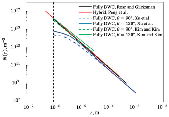
Figure 1.
Drop size distribution from the literature on different conditions. Rose and Glicksman [12], Kim and Kim [16], Xu et al. [19], and Peng et al. [21].
The drop size distribution of small drops, which is bounded between the minimum and effective radius, is derived by applying the population balance model. Two boundary conditions are applied between the drop size distribution of small drops and large drops at
The final expression of drop size distribution for drops growing by direct condensation is [14,16]
where , , , and are group parameters. The profile can be determined by applying the boundary conditions Equations (7) and (8). The heat transfer through a single drop for a given radius size and contact angle is related to the drop growth rate, as follows [16]:
where the drop growth rate is defined as [14,44]
The heat transfer through a drop is obtained by considering all thermal resistances in the path of heat transfer. The final form is given as [16]
The above expression combines all thermal resistances from steam-saturated temperature to solid surface temperatures due to liquid–vapor interfacial resistance, drop curvature, the coating layer [16], and conduction through a drop [5].
2.2. Proposed Drop Size Distribution
The proposed drop size distribution model describes a drop population on a hybrid surface where one DWC region is bounded between FWC regions. It is a product of simulation work for drop growth by direct condensation, considering the coalescence of drops, drops sweeping area beneath them, and drops merging with neighboring FWC regions. The model takes into consideration the variation of effective radius which is dependent on the total temperature drop, , or nucleation sites, , as given in Equations (1)–(3), and it defines the intensity of coalescence. Another important factor is the maximum drop radius, , provided by Equation (4), which indicates a drop departing radius. The variation in includes the effect of surface inclination and surfacer hydrophobicity which is measured by the contact angle. Therefore, simulation work is conducted for vertical smooth plate with different hydrophobicity levels and total temperature drop values.
Another factor to consider is the DWC region width, . In a special case, when the drop maximum diameter is equal to , drops merging with neighboring FWC regions become the only surface renewal mode. On the other hand, when is infinite, it implies full DWC, and sweeping drops become the only surface renewal mode.
2.2.1. Simulation Procedure
Our simulation work is divided into multiple modules that are capable of illustrating the process of drop growth, generating newly formed drops, and surface renewal by sweeping and merging. All measured distances are based on a three-dimensional domain; however, simulation work is performed in two dimensions or from a top view.
In the initial condition module, the effective radius and maximum radius are prescribed. All droplets are randomly distributed without overlapping on a quadrilateral domain defined by coordinates and , where and are domain width and length, respectively. Drops size at the initial state varies from 0.2 to 0.2 . Three distances are measured for each drop: x-axis coordinate , y-axis coordinate , and the radius , where subscript indicates drop number, as shown in Figure 2a. These distances are updated throughout the simulation process because drop location and size are subject to change.
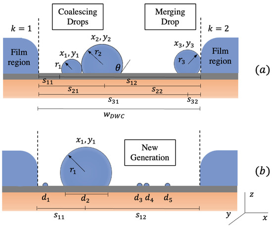
Figure 2.
Demonstration of DWC process: (a) coalescence and merging of drops and (b) drop generation on renewed region.
In addition, distances from each drop center to all boundaries are measured and updated, where is a boundary number. Only drops completely or partially within the domain are accounted for in estimating the area fraction, . Therefore, when the difference between distance with upper or lower boundaries and drop radius is negative, it indicates that the drop is partially outside the boundary.
The second module is used to represent drop growth by direct condensation. Substituting Equation (10) into (12) and solving for gives
is specified in an initial state, since it determines the rate of drop growth. By applying the Euler integration method, a small increment in radius is applied to each drop for every time step .
To maintain coalescence as the dominant mode for drop growth, new drops are continuously generated with a radius size equal to half of the effective radius. Therefore, the rate of generation of new drops in this module is dependent on the area available to them at every time step. New generations of drops are created without overlapping with older drops and domain boundaries.
In the next module, drops are checked for coalescence by measuring two distances: the distance between each drop center to another and the sum of their radius. Drops overlapping is checked based on the three-dimensional domain when the following condition is met [19]:
where . Figure 2 simply illustrates the coalescence between two drops. Overlapped drops are deleted, and a new larger drop is formed at the center of the mass of overlapped droplets and a volume equal to the sum of their volumes. The new drop location and size are updated to check for further overlapping until no coalescence is detected.
Dropwise and filmwise surfaces are integrated, and surface renewal is dependent on drops merging with neighboring films, as shown in Figure 2. It is assumed that the film region height is larger than the assigned maximum radius. Merging is detected when Equation (13) is met with either side of dropwise boundaries.
When a drop size reaches the maximum radius, it departs from its origin and sweeps all drops beneath it. This is simulated by deleting any drop that reaches or exceeds the maximum radius as well as deleting all drops completely and partially located within the swept area. In some cases, a departing droplet experiences excessive coalescence and as a result, it will exceed the maximum diameter before departing. Checking for swept drops occurs when all the following conditions are satisfied:
, and denote coordinates and the radius of a departing drop. The right-hand side of the second and third conditions Equations (17) and (18) are the right and left boundaries of swept area. When sweeping occurs, the area of the departing drop and the swept area are recorded.
After the modules are completed, a new set of , , and are measured for all drops, and the area fraction is calculated by summing all of the drops’ base area. A drop’s base area is assumed to be circular, and its diameter for a given contact angle is
The simulation process is summarized in Figure 3. It includes all equations that are used during one run. The area fraction occupied by all drops is recorded for every time step for data regression and post-processing. The figure shows where all drop locations and sizes are updated throughout one-time intervals to ensure accuracy.
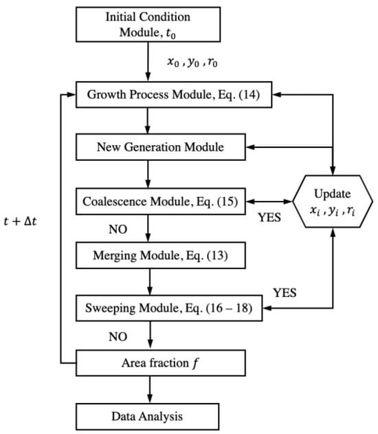
Figure 3.
Simulation procedure (modules) for one time step with an update of drops’ locations and sizes.
The simulation is also applicable for full-DWC regions when considering imaginary boundaries instead. Only a portion of drops occupied within the domain are accounted for in estimating , and Equation (15) is applied for all boundaries.
2.2.2. Data Analysis
The population density on the condensing surface can be obtained by knowing the average area occupied by drops and the average spacing between drops that is available to the next generation of drops. From the simulation work, is recorded at every time step during the growth process for given conditions. When the value tends to fluctuate within a certain range, a steady state condition is reached, and the results are to be confirmed. The average is determined by applying the mean value theorem to the fluctuation.
The average spacing between drops can be approximated by assuming all drops of the older generation are equal in size and uniformly distributed, as shown in Figure 4. The distances between their centers form an equilateral triangle [12], and the corresponding expression in terms of is given by
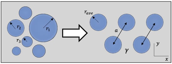
Figure 4.
Random drops on the left side are re-arranged to estimate the average spacing between two generations of drops as shown on the right side.
The drop size distribution is given as follows [10]:
where is the area fraction covered by the drop with a radius greater than . Alternatively, Equation (22) can be rewritten in the following form:
Thus, the drop size distribution is obtained by dividing (23) by the droplet base area, and it is given with respect to the contact angle and :
Outcomes from simulation work include sets of and values for various conditions. These values are curve-fitted in the form of Equation (24) to produce new values for exponent . The drop size distribution for small drops is obtained from the population model with respect to the contact angles and when applying the boundary conditions, as in Equations (7) and (8):
A drop size distribution profile is defined by a value of n for a given maximum radius and effective radius. The same process is followed for full DWC, except that merging is ignored. The drop size distribution for DWC within the hybrid surface is to be compared with that of full-DWC.
3. Results and Discussion
Intensive simulation runs were performed to understand the effect of many parameters on drop size distribution. For hybrid surfaces, the effect of DWC region width is analyzed, since it plays an important role in surface renewal. To demonstrate its effect, the ratio of maximum drop diameter to is introduced (), where its value ranges from 0 to 1, and 0 implies a full-DWC surface. Drop growth and surface renewal processes are based on dimensionless parameters, and is not necessarily definite. When the comparison is made with full DWC, is set at 0.5 mm. Work is also performed for total temperature drop, , of , and , and values of the effective radius are obtained from Equation (2) for variable nucleation sites . The contact angle is constant throughout the analysis and equals 120.
The water-saturated temperature is 373 K, and enthalpy of vaporization is 2257 kJ/kg. All properties such as thermal conductivity, density, and surface tension are evaluated at average temperatures. A run period is set at 40 s with a time interval of 20 ms.
3.1. Simulation Work
All drops are allowed to grow by direct condensation at a slow rate depending on their size and . At the same time, new drops are generated with a size of 0.2 at every time step to ensure the dominance of coalescence. Condensing surfaces for DWC within the hybrid surface are illustrated in Figure 5 for values of 0.125, 0.25, 0.5, 0.75, and 1 in addition to a full-DWC surface with a mm domain. In all surfaces, larger drops are developed due to successive coalescence that subsequently causes surface renewal. Figure 5 shows areas where surface renewal is caused by sweeping, e.g., within the bold rectangle, and others caused by merging, e.g., within the bold circles.
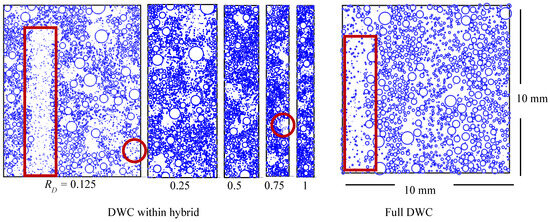
Figure 5.
Condensing surfaces of DWC within a hybrid surface with different maximum diameter to DWC region width ratios, RD, in comparison with the full-DWC domain. Swept areas are indicated by bold rectangles, and merged areas are indicated by bold circles.
The simulation work is a reproductive process of drop growth and surface renewal. A demonstration for DWC within a hybrid surface with equaling (a) 0.5 and (b) 1 is shown in Figure 6. In initial condition phase A, all drops are randomly distributed without overlapping. When the simulation starts, the surface becomes more populated due to the generation of new drops and direct condensation, as indicated in phase B. Larger drops started to appear due to coalescence, and drop merging became obvious in phase C until the surface occupied by drops was minimal, as shown in phase D. Surface renewal was achieved in both cases, but we observed that it was faster at a higher value. Comparing cases (a) and (b) in Figure 6, the drops’ population density is close in each phase. However, the time cycle taken to reach phase D is shorter in case (b). This is because drops merging sideways into filmwise regions are more evident.
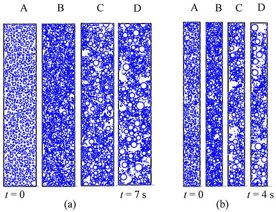
Figure 6.
Simulation work for DWC within a hybrid surface: (a) RD = 0.5 (b) RD = 1.
3.2. Model Validation
To verify the validity of the current work, simulation was first performed for a full-DWC surface when the drop contact angle was 90 without the generation and sweeping of drops. Only drop growth and coalescence were demonstrated, and a run was executed whenever a drop reached or exceeded . Runs were performed for different starting configurations such as drop size and location. Random and uniform distribution of drops were applied in the initial state. In some starting conditions, all drops had the same radius size, and in other conditions, drops had a random radius size. In addition, different packing was considered, where different initial numbers of drops are used. The average area fraction for full DWC and the corresponding exponent were 0.547 and 0.329, respectively. These results were close to 0.55 and [12], with an error of less than 0.6%. This serves as a benchmark for predicting the effect of surface renewal within the DWC surface on drop size distribution.
3.3. Area Fraction
Demonstrations of drop generation and surface renewal were then integrated into the simulation of DWC within a hybrid surface. Sample results are shown in Figure 7, where tends to fluctuate within a certain range. Small fluctuations indicate drop growth, formation of new drops, and drop coalescing processes. Sharp declines signal surface renewal due to the sweeping of departing drops, which is evident in Figure 7a for = 0.125 and Figure 7b for full DWC. The merging of small drops into film regions also contributes to fluctuation, whereas merging of larger drops is indicated by small declines.
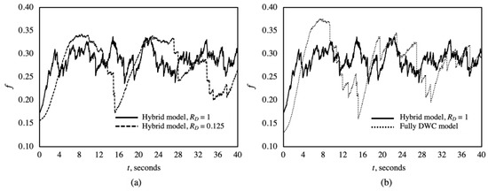
Figure 7.
Area fraction fluctuation for simulation runs: (a) a comparison between the hybrid model at RD = 0.125 and 1; (b) a comparison between the hybrid model at RD = 1 and full DWC.
Figure 7 shows that fluctuates between upper and lower limits. It was observed that the change in the upper limits was less sensitive, showing that condensation was at the same packing level. On the other hand, lower limit variation was more obvious and was dependent on the surface renewal mode. For small , in hybrid and full-DWC cases as shown in Figure 7, the lower limit of was small due to sweeping. As increased towards unity, the lower limits became higher and dependent only on merging.
The average area fraction with respect to is presented in Figure 8 for total temperature drops ( of , and . For = 0, the results are for a full-DWC surface with set at 0.5 mm. The average showed the lowest values when equaled 0.125, where surface renewal was achieved by both sweeping and merging. As approached 0.75, the average increased as surface renewal became more dominated by merging. For at 1, intensive merging occurred and, as a result, average values dropped. Figure 8 shows that has a minimal effect on the average , and it mainly affects the rate of growth process.
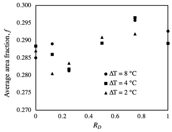
Figure 8.
Average area fraction with respect to RD variation for different total temperature drops.
From Figure 8, values of average area fraction are bounded between 0.28 and 0.296, which are lower than the reported values in the literature for full DWC. The average from simulation work [12,22] is about 0.55, and surface coverage reported by [45] tends toward a constant value of 0.5. It is evident that surface renewal by sweeping causes alteration in surface coverage for a full-DWC surface, which ranges from 0.2 to 0.8 [19]. The deviation in surface coverage presented in the current work is not only due to the sweeping effect but also due to drops migrating sideways to the film regions.
3.4. Surface Renewal
To evaluate the impact of drops merging into film regions on surface coverage, surface renewal, and drop size distribution, the following points are considered. Surface renewal by sweeping is dependent on the locations of departing drops. Departing at a higher elevation will result in a higher swept area and a lower value and vice versa. This is shown in Figure 7, where a larger decline signals sweeping at higher elevations. In addition, sometimes successive departing of nearly vertically aligned drops causes sweeping of common area. This will leave drops within the unswept region to grow undisrupted, forming a more populated region and maintaining higher values. Based on previous points, the elevation of all departing drops and corresponding swept areas is evaluated at half surface height, . This approach disregards the effect of successive sweeping of common regions and averages the location of departing drops.
For each simulation run, the number of departing drops, their corresponding swept areas, and the sum of merging drops’ base areas are all recorded. The total surface renewal rates of sweeping and merging drops per unit area, s−1 are presented in Figure 9. As increases, surface renewal rates for DWC within the hybrid surface decline then rise for all . In comparison with full DWC, surface renewal within the hybrid surface is improved for 0.5. The shape of one surface renewal profile or curvature is due to the effect of merging drops. The contribution of merging is indicated by the fraction number at each condition in Figure 9. The value 0 implies that merging has no effect and sweeping is the only mode of surface renewal. When reaches unity, surface renewal rates are improved by 85% at and 64% at .
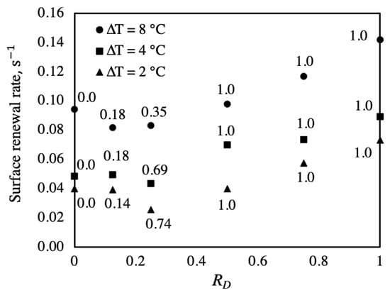
Figure 9.
Total surface renewal rate based on domain area showing the contribution of merging.
The FWC region width is another important parameter, and as a result, surface renewal rates per unit area are degraded. In the present work, FWC region width was ignored and left for future analysis in evaluating the thermal performance of hybrid surfaces.
3.5. Drop Size Distribution for Hybrid Surfaces
From the simulation work, values of lie between 0.280 and 0.296 for from 0.125 to 1, and an average of 0.288 is selected to reflect variation only. Data fitting and in the form of Equation (26) is performed to outline new sets of exponents for different and values.
The results of drop size distribution for DWC within the hybrid surface for of 0.5 and 2.0 mm are illustrated in Figure 10. Results are also compared with Equation (6) for equaling for full DWC when is set at 1 × 10⁻⁶ m. The main dissimilarity is that hybrid profiles show lower logarithmic slopes n of 0.167 and 0.134 at values of 0.5 and 2.0 mm, respectively. Steeper slopes in hybrid N(r) reveal not only the intensity of drops’ coalescence but also the disappearance of large drops due to surface renewal. More specifically, merging reduces the large drop population, allowing drops of smaller size to grow without disruption, which is indicated by hybrid profiles of effective radius , as shown in Figure 10. The change in is 73% and 41% for values of 0.5 and 2.0 mm, respectively, when compared with full DWC.
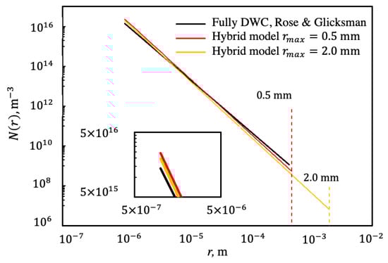
Figure 10.
Drop size distribution model for different values with comparison when n = 1/3 [12] at a given −6 m.
From Equation (2), the effective radius is dependent on the nucleation number that ranges from to sites/ and determines the population of small drops. Obtained values for n exponent are used in (9) to define the drop size distribution of small drops . The impact of variation on hybrid and is illustrated in Figure 11 for at 0.5 mm. The lower value reflects a steeper logarithmic slope and a lower value, which is presented in Figure 11 at . When coalescence starts at lower , it creates more area for more drops to nucleate and accelerates the process of coalescence. The percent change at is up to 85% between at and sites/. This is also because surface renewal due to sweeping and merging will result in more dry areas for more nucleation.
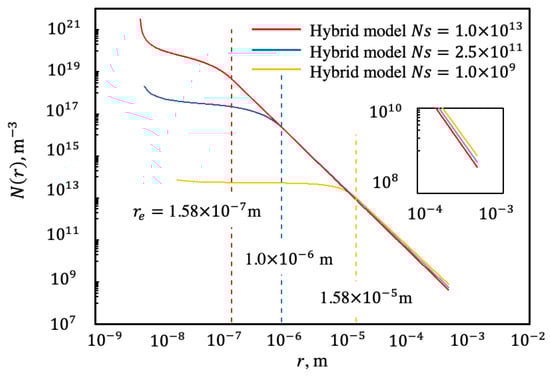
Figure 11.
Drop size distribution for different and corresponding for given of 0.5 mm.
Data regression is performed to produce values for exponent in terms of from 0.5 × 10⁻³ to 2.0 × 10⁻³ m and from 1.6 × 10⁻⁷ to 5.0 × 10⁻⁵ m, corresponding to from 1.0 × 10¹³ to 1.0 × 10⁸ sites/. The final expression for DWC within the hybrid surface is given in the following polynomial form:
The expression has a sum of the squared estimate of and a coefficient of determination of 0.9725. In addition to Equation (26), the model results for exponent are also given in Figure 12 for different and . It generally has lower values than 1/3 due to the consideration of surface renewal by sweeping and merging. It also reflects the coalescence intensity, which is based on drop nucleation. The simple expression can be utilized in Equations (23)–(25) to provide a better understanding of the drop population and estimate the thermal performance of DWC within hybrid surfaces.
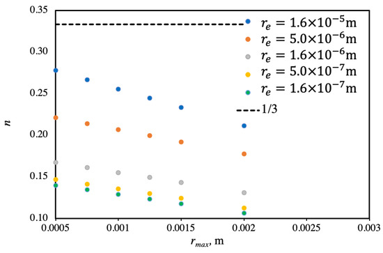
Figure 12.
Model results for exponent n with respect to and .
4. Conclusions
The present work considers the surface renewal and coalescence intensity of dropwise condensation within a hybrid surface. The developed model illustrates the process of drop growth, drop generation, departing, and merging into film regions. Drops’ population density and surface renewal for various ratios of maximum drop radius to DWC region width, , have been studied.
The drop size distribution for DWC within a hybrid surface was developed based on modifying the exponent of 1/3 in the empirical formula for large drops and the population model for small drops. The present work provides in a polynomial form that corresponds to various effective and maximum radii.
- (a)
- From simulation work, area fraction occupied by drops was estimated for values of 0.125, 0.25, 0.5, 0.75, and 1 and a total temperature drop of 2, 4, and 8 . The area fraction, , ranged from 0.28 and 0.296, and an average of 0.288 was selected to reflect the variation of .
- (b)
- The average of 0.288 for DWC within the hybrid surface was different from the reported value of 0.55 for full DWC due to the consideration of surface renewal by sweeping and merging.
- (c)
- Surface renewal was improved by the hybrid surface for values greater than 0.5 due to the contribution of merging. When reached unity, the surface renewal rate was enhanced by 85% at and 64% at .
- (d)
- Drop size distribution for DWC in a hybrid surface generally shows a steeper slope on the logarithmic scale, where the population of larger drops is less than that of full DWC due to the combined effect of surface renewal and intensive coalescence.
- (e)
- Increasing drops’ nucleation or lowering the effective radius accelerates the surface renewal and coalescence process for a given maximum radius.
- (f)
- An exponent of 1/3 in the drop size distribution of large and small drops was modified for DWC on a hybrid surface with the consideration of surface renewal by sweeping and merging and intensive coalescence. The modification is in a simple polynomial form of effective and maximum radii.
In future work, the modified drop size distribution will be utilized to develop and evaluate the thermal performance of hybrid dropwise condensation.
Author Contributions
Conceptualization, A.A.; Formal analysis, A.A., M.A. and H.A.-Z.; Methodology, A.A.; Resources, A.A.; Software, A.A. and M.A.; Validation, A.A. and M.A.; Writing—original draft, A.A., M.A. and H.A.-Z.; Writing—review & editing, A.A., M.A. and H.A.-Z. All authors have read and agreed to the published version of the manuscript.
Funding
This research received no external funding.
Institutional Review Board Statement
Not applicable.
Informed Consent Statement
Not applicable.
Data Availability Statement
Data are contained within the article.
Conflicts of Interest
The authors declare no conflicts of interest.
Nomenclature
| distance between neighboring drops’ centers [m] | |
| group parameters | |
| group parameters | |
| area fraction | |
| gravitational force [m/s2] | |
| G | growth rate |
| interfacial heat transfer coefficient [W/m2.K] | |
| latent heat of vaporization [J/kg] | |
| coating layer thermal conductivity [W/m.K] | |
| condensate thermal conductivity [W/m.K] | |
| exponent in drop size distribution | |
| small drop size distribution [m−3] | |
| large drop size distribution [m−3] | |
| nucleation sites [m−2] | |
| heat transfer through a single drop [W] | |
| drop radius [m] | |
| effective radius [m] | |
| maximum radius [m] | |
| minimum radius [m] | |
| s | distance between two drops’ centers |
| ratio of maximum drop diameter to DWC width | |
| saturation temperature [K] | |
| dropwise condensation region width [m] | |
| Greek Symbols | |
| total temperature drop [°C] | |
| contact angle [°] | |
| advanced contact angle [°] | |
| receding contact angle [°] | |
| viscosity [Pa.s] | |
| surface tension [N/m] | |
| steam density [kg/m3] | |
| ratio of maximum radius | |
| coating layer thickness [m] | |
| Abbreviations | |
| DWC | dropwise condensation |
| FWC | filmwise condensation |
References
- Dai, B.; Wang, Q.; Liu, S.; Zhang, J.; Wang, Y.; Kong, Z.; Chen, Y.; Wang, D. Multi-objective optimization analysis of combined heating and cooling transcritical CO2 system integrated with mechanical subcooling utilizing hydrocarbon mixture based on machine learning. Energy Convers. Manag. 2024, 301, 118057. [Google Scholar] [CrossRef]
- Dai, B.; Wu, T.; Liu, S.; Qi, H.; Zhang, P.; Wang, D.; Wang, X. Flow boiling heat transfer characteristics of zeotropic mixture CO2/R152a with large temperature glide in a 2 mm horizontal tube. Int. J. Heat Mass Transf. 2024, 218, 124779. [Google Scholar] [CrossRef]
- Jakob, M. Heat Transfer in Evaporation and Condensation. Mech. Eng. 1936, 58, 729–739. [Google Scholar]
- LeFevre, E.; Rose, J. An Experimental Study of Heat Transfer by Dropwise Condensation. Int. J. Heat Mass Transf. 1965, 8, 43–90. [Google Scholar] [CrossRef]
- LeFevre, E.J.; Rose, J.W. A theory of heat transfer by dropwise condensation. In Proceedings of the International Heat Transfer Conference 3, Chicago, IL, USA, 7–12 August 1966. [Google Scholar]
- Neumann, A.W.; Abdelmessih, A.H.; Hameed, A. The Role of Contact Angles and Contact Angle Hysteresis in Dropwise Condensation Heat Transfer. Int. J. Heat Mass Transf. 1978, 21, 947–953. [Google Scholar] [CrossRef]
- Fatica, N.; Katz, D.L. Dropwise Condesation. Chem. Eng. Prog. 1949, 45, 661–674. [Google Scholar]
- Rose, J.W. Dropwise Condensation Theory. Int. J. Heat Mass Transf. 1981, 24, 191–194. [Google Scholar] [CrossRef]
- Tanaka, H. A Theoretical Study of Dropwise Condensation. Trans. ASME 1975, 97, 72–78. [Google Scholar] [CrossRef]
- Rose, J.W. Some Aspects of Condensation Heat Transfer Theory. Int. Commun. Heat Mass Transf. 1988, 15, 449–473. [Google Scholar] [CrossRef]
- Rose, J.W. Condensation heat transfer fundamentals. Chem. Eng. Res. Des. 1998, 76, 143–152. [Google Scholar] [CrossRef]
- Rose, J.W.; Glicksman, L.R. Dropwise Condensation—The Distribution of Drop Sizes. Int. J. Heat Mass Transf. 1973, 16, 411–425. [Google Scholar] [CrossRef]
- Maa, J.R. Drop Size Distribution and Heat Flux of Dropwise Condensation. Chem. Eng. J. 1977, 16, 171–176. [Google Scholar] [CrossRef]
- Abu-Orabi, M. Modeling of heat transfer in dropwise condensation. Int. J. Heat Mass Transf. 1998, 41, 81–87. [Google Scholar] [CrossRef]
- Lan, Z.; Ma, X.; Zhou, X.; Wang, M. Dropwise condensation heat transfer: Effect of the liquid-solid surface free energy difference. J. Enhanc. Heat 2009, 16, 61–71. [Google Scholar] [CrossRef]
- Kim, S.; Kim, K.J. Dropwise Condensation Modeling Suitable for Superhydrophobic Surfaces. J. Heat Transf. 2011, 133, 081502. [Google Scholar] [CrossRef]
- Hu, H.; Tang, G. Theoretical investigation of stable dropwise condensation heat transfer on horizontal tube. Appl. Therm. Eng. 2014, 62, 671–679. [Google Scholar] [CrossRef]
- Bahrami, H.R.T.; Saffari, H. Mathematical Modeling and Numerical Simulation of Dropwise Condensation on an Inclined Circular Tube. J. Aerosp. Technol. Manag. 2017, 9, 476–499. [Google Scholar] [CrossRef]
- Xu, W.; Lan, Z.; Liu, Q.; Du, B.; Ma, X. Droplet size distribution in dropwise condensation heat transfer: Considering of droplet overlapping and multiple re-nucleation. Int. J. Heat Mass Transf. 2018, 127, 44–54. [Google Scholar] [CrossRef]
- Wang, J.; Ma, Z.; Li, G.; Sundén, B.; Yan, J. Improved modeling of heat transfer in dropwise condensation. Int. J. Heat Mass Transf. 2020, 155, 119719. [Google Scholar] [CrossRef]
- Peng, B.; Ma, X.; Lan, Z.; Xu, W.; Wen, R. Analysis of condensation heat transfer enhancement with dropwise-filmwise hybrid surface: Droplet sizes effect. Int. J. Heat Mass Transf. 2014, 77, 785–794. [Google Scholar] [CrossRef]
- Alhashem, A.; Khan, J. Heat Transfer Analysis for Dropwise-Filmwise Hybrid Surface of Steam on Vertical Plate. J. Therm. Sci. 2021, 30, 962–972. [Google Scholar] [CrossRef]
- Denoga, G.J.C.; Balbarona, J.A.; Salapare, H.S., III. Development of Drop Size Distribution Model for Dropwise Condensation on a Superhydrophobic Surface. Colloids Interfaces 2023, 7, 53. [Google Scholar] [CrossRef]
- Liu, W.; Gui, M.; Zha, Y.; Li, Z. Numerical Investigation of the Effect of Surface Wettability and Rotation on Condensation Heat Transfer in a Sludge Dryer Vertical Paddle. Energies 2023, 16, 901. [Google Scholar] [CrossRef]
- Askan, S.; Rose, J. Dropwise Condensation–The effect of thermal properties of the condeser material. Int. J. Heat Mass Transf. 1973, 16, 461–467. [Google Scholar]
- Orejon, D.; Shardt, O.; Gunda NS, K.; Ikuta, T.; Takahashi, K.; Takata, Y.; Mitra, S.K. Simultaneous dropwise and filmwise condensation on hydrophilic microstructured surfaces. Int. J. Heat Mass Transf. 2017, 114, 187–197. [Google Scholar] [CrossRef]
- Ren, S.; Gao, S.; Xu, Z.; Wu, S.; Deng, Z. Experimental Study on the Condensation Heat Transfer on a Wettability-Interval Grooved Surface. Appl. Sci. 2023, 13, 10518. [Google Scholar] [CrossRef]
- Kumagai, S.; Tanaka, S.; Katsuda, K.; Shimada, R. On the enhancement of filmwise condensation heat transfer by means of the coexisting with dropwise condensation sections. Exp. Heat Transf. 1991, 4, 71–82. [Google Scholar] [CrossRef]
- Ma, X.; Zhou, X.; Lan, Z. Experimental Investigation of Enhancment of Dropwise Condensation Heat Transfer of Steam-Air Mixture: Falling Droplet Effect. J. Enhanc. Heat Transf. 2007, 14, 295–305. [Google Scholar] [CrossRef]
- Alwazzan, M.; Egab, K.; Peng, B.; Khan, J.; Li, C. Condensation on hybrid-patterned copper tubes (II): Visualization study of droplet dynamics. Int. J. Heat Mass Transf. 2017, 112, 950–958. [Google Scholar] [CrossRef]
- Alwazzan, M.; Egab, K.; Peng, B.; Khan, J.; Li, C. Condensation on hybrid-patterned copper tubes (I): Characterization of condensation Heat Transfer. Int. J. Heat Mass Transf. 2017, 112, 991–1004. [Google Scholar] [CrossRef]
- Peng, B.; Ma, X.; Lan, Z.; Xu, W.; Wen, R. Experimental investigation on steam condensation heat transfer enhancement with vertically patterned hydrophobic—hydrophilic hybrid surfaces. Int. J. Heat Mass Transf. 2015, 83, 27–38. [Google Scholar] [CrossRef]
- Wu, Y.T.; Yang, C.X.; Yuan, X.G. Drop Distribution and numerical simulation of dropwise condensation Heat Transfer. Int. J. Heat Mass Transf. 2001, 44, 4455–4464. [Google Scholar] [CrossRef]
- Mei, M.; Yu, B.; Cai, J.; Luo, L. A fractal analysis of dropwise condensation Heat Transfer. Int. J. Heat Mass Transf. 2009, 52, 4823–4828. [Google Scholar] [CrossRef]
- Qi, B.; Wei, J.; Zhang, L.; Xu, H. A fractal dropwise condensation heat transfer model including the effects of contact angle and drop size distribution. Int. J. Heat Mass Transf. 2015, 83, 259–272. [Google Scholar] [CrossRef]
- Bonner, R.W., III. Correlation for dropwise condensation heat transfer: Water, organic fluids, and inclination. Int. J. Heat Mass Transf. 2013, 61, 245–253. [Google Scholar] [CrossRef]
- Rose, J.W. Further aspects of dropwise condensation theory. Int. J. Heat Mass Transf. 1976, 19, 1363–1370. [Google Scholar] [CrossRef]
- Singh, M.; Pawar, N.D.; Kondaraju, S.; Bahga, S.S. Modeling and Simulation of Dropwise Condensation: A Review. Indian Inst. Sci. 2019, 99, 157–171. [Google Scholar] [CrossRef]
- Alhashem, A.E. A Model for Condensation Heat Transfer in Hydrophobic-Hydrophilic Surfaces. Doctoral Dissertation, University of South Carolina, Columbia, SC, USA, 2019. [Google Scholar]
- Croce, G.; Suzzi, N. Numerical Simulation of Dropwise Condensation of Steam over Hybrid Surfaces via New Non-Dimensional Heat Transfer Model. Fluids 2023, 8, 300. [Google Scholar] [CrossRef]
- Graham, C.; Griffith, P. Drop Size Distributions and Heat Transfer in Dropwise Condensation. Int. J. Heat Mass Transf. 1972, 16, 337–346. [Google Scholar] [CrossRef]
- Wu, H.W.; Maa, J.R. On the heat transfer in dropwise condensation. Chem. Eng. J. 1976, 12, 225–231. [Google Scholar] [CrossRef]
- Extrand, C.E.; Kumagai, Y. Liquid drops on an inclined plane: The Relation Between Contact Angle, Drop Shape and Retentive Force. J. Colloid Interface Sci. 1995, 170, 515–521. [Google Scholar] [CrossRef]
- Randolph, A.D. Theory of Particulate Processes, 2nd ed.; Academic: New York, NY, USA, 1988. [Google Scholar]
- Mei, M.; Yu, B.; Zou, M.; Luo, L. A numerical study of growth mechanism of dropwise condensation. Int. J. Heat Mass Transf. 2011, 54, 2004–2013. [Google Scholar] [CrossRef]
Disclaimer/Publisher’s Note: The statements, opinions and data contained in all publications are solely those of the individual author(s) and contributor(s) and not of MDPI and/or the editor(s). MDPI and/or the editor(s) disclaim responsibility for any injury to people or property resulting from any ideas, methods, instructions or products referred to in the content. |
© 2024 by the authors. Licensee MDPI, Basel, Switzerland. This article is an open access article distributed under the terms and conditions of the Creative Commons Attribution (CC BY) license (https://creativecommons.org/licenses/by/4.0/).