Article

Experimental Study of Different Radial Jet Drilling Parameters and Operation Regimes for Effective Well Stimulation

by
Sergey Krivoshchekov
*,
Alexander Kochnev
,
Evgeny Ozhgibesov
and
Alexey Yuzhakov
Petroleum Geology Department, Perm National Research Polytechnic University, Komsomolsky Prospect 29, 614990 Perm, Russia
*
Author to whom correspondence should be addressed.
Appl. Sci. 2024, 14(3), 1149; https://doi.org/10.3390/app14031149
Submission received: 12 December 2023 / Revised: 23 January 2024 / Accepted: 25 January 2024 / Published: 30 January 2024
(This article belongs to the Section Earth Sciences)

Abstract

:
Radial waterjet drilling technology presents a modern solution to enhance oil recovery. This technology has already established itself at a number of oilfields, but selecting the best operational and technical parameters for radial waterjet drilling channels remains an open and poorly studied question. The purpose of this work is to study the process of radial channel drilling in detail by means of bench tests in laboratory conditions. The study models static and dynamic waterjet stimulation and determines the optimum values of operating parameters affecting waterjet nozzle speed in the channel that is being drilled. As a result of the conducted experiments, it was found that the dynamic mode of stimulation is more effective than the static mode. Therefore, development and introduction of additional modules to the equipment arrangement to ensure constant forced linear reciprocating motion of the waterjet nozzle will significantly improve the efficiency and speed of waterjet drilling. Further design and practical application of the aforementioned novel technical solution will significantly improve the performance of radial drilling technology in enhanced oil recovery.

1. Introduction

Radial drilling of high-permeability waterjet channels is an unconventional technology for drilling multiple small-diameter radial channels in oil-producing wells by using high-pressure jets of working agent [1]. This technology is characterized as cost efficient [2] but has a number of disadvantages: lack of the possibility to determine and control the trajectory of waterjet channel drilling, lack of knowledge of the best operational and technical parameters to be considered in selecting and operating special equipment. Nevertheless, the technology of radial drilling of waterjet channels can be highly effective in the oil production industry, as it offers a number of undeniable advantages cited in [3]. Consolidation of the results of modern research and technical achievements will soon make it possible to draw an unambiguous conclusion about the high efficiency of practical application of radial drilling technology.
Figure 1 shows a schematic diagram of the working principle of the jet drilling. The drilling fluid is fed into the nozzle, which in turn forms the front and rear jets. The main function of the front jets is to destroy the rock and form a hole with a diameter of several feet. The function of the back jets is to increase the pulling force of the nozzle, and they can also enlarge the hole by cleaning the wall of the hole while removing sludge. The process of nozzle movement and rock destruction depends on the balance of the acting forces, or rather on the distribution of volumes and velocity of the front and rear jets. In more detail, the fundamental principles of radial jet drilling and the mechanisms of self-promotion of nozzles through the created channel are discussed in the article [4].
In [5], the authors describe the experience of modeling the process of drilling radial channels in a fractured type of reservoir, which is evaluated as successful further in the study; in particular, the waterjet channel in the fractured type of reservoir connects the existing fractures, thereby improving filtration in the reservoir zone under effect.
In addition to the proven efficiency in laboratory conditions, the technology of radial drilling of waterjet channels also shows good results in industrial conditions. For example, [6] presents the results of oil production increase in five target wells by 135% on average. In [3], the technology under consideration was applied at the Tarim gas condensate field (China), where a 200% increase in oil production was obtained. Similar positive effects resulting from the application of radial drilling technology were obtained at such oil fields as Donelson West (USA) [7], Belayim (Egypt) [8], Vakhitovskoye (Russia) [9], etc. Study [10] presents the results of experimental application of waterjet radial drilling technology at three oil producing wells and one gas well in India. As a result of pilot application of the technology, a significant increase in the yield of oil-producing wells was obtained, but there was no effect on the gas well. Study [9] analyzes Russian experience in the application of waterjet radial drilling technology at Vakhitovskoye oil field, where oil yield increased between 1.5–5.0 times in different producing wells. Study [11] aimed at investigating the effect of using an acid compound as a disintegrating agent for carbonate rock. The authors conducted a comparative study using fresh water and an acid compound containing 15% HCl. Based on the obtained photos of the test results, the waterjet channel drilled with fresh water has clearly defined “rays” (rock excavations in the form of rays), while when using an acid compound, the space between the rays is partially exposed to destruction which further expands the channel. Studies [12,13,14] show that the application of waterjet radial drilling technology is most effective in environments with increased oil viscosity, which typically have stagnant zones in low-permeability areas of the reservoir. In studies [15,16], methods of statistical analysis were used to demonstrate that the waterjet radial channel technology is more effective in comparison with the technology of hydrochloric-acid treatment of bottomhole formation zone and the technology of “reperforation/quick-gain perforation”.
Today, multiple equipment configurations are used for waterjet stimulation both in the oil and gas industry and in the construction and public utility sector, including waterjet nozzles of various designs. For example, study [17] investigates energy converting efficiency and proposes the most optimal design of the waterjet nozzle determined by numerical modeling.
As a rule, waterjet nozzles have separate holes for front and rear jets. The waterjet nozzle is self-propelled, i.e., its movement inside the rock along the radial channel it creates is propelled by the reactive forces of jets from the rear holes of the nozzle. Literature [4] also describes important aspects of influence of distance between the waterjet nozzle and the rock under stimulation on the efficiency of radial drilling, but these phenomena are not fully studied. The main tool for radial drilling was borrowed from the municipal economy. Hydraulic monitoring nozzles are widely used for cleaning the inner surface of various types of pipelines. Pipe blockages are removed using through-type nozzles, rotary type nozzles or punch type. Figure 2 schematically shows the specified types of nozzles. Most often, through-type nozzles are used to intensify oil or gas production. The bodies of such nozzles are monolithic and have separate holes for front and rear jets. This specific nozzle type is reliable from a constructive point of view, however, the area of impact of the frontal jets will depend on the number of front separate holes. The rotary nozzle type has a housing consisting of two different parts, one of which rotates due to the pumped flow through the nozzles. In the literature [18,19], there are nozzle designs with both a front rotating part and a rear one. The use of this type of nozzle makes it possible to cover the treated area more evenly. In the case of oil and gas production, this nozzle type will enable the creation of highly permeable radial channels of the correct geometry with a circular cross section. However, this type of nozzle is prone to a large number of breakdowns. The third type of nozzle does not have front separate holes and is not used in oil and gas production. This nozzle type is used only in the communal sector. Further in this article, only through-type nozzles are considered as the most common in the oil and gas industry at the moment.
The process of radial drilling of highly permeable channels comprises several key stages: cutting off the side channel (cutting off the metal casing), hydraulic jet destruction of the rock, and washing out the resulting sludge to the surface. Each of the listed stages must be considered separately in detail. For example, the issue of raising cuttings by liquid flows during the radial drilling process is discussed in detail in [20]. However, this article is devoted to a detailed study of only the stage of rock destruction in order to create a highly permeable channel.
In [20], the authors made a significant contribution to the study of waterjet nozzle movement and the forces propelling it. The study presents the results of mathematical modeling of the thrust force of the waterjet nozzle motion and shows an example of determining the optimal design parameters of the waterjet nozzle. The authors made very important conclusions that underlie the most effective approach to practical application of radial drilling technology for the purpose of enhanced oil recovery, specifically:
  • Self-propulsion capability of the waterjet nozzle decreases significantly as the number of front holes increases.
  • The angle of the front holes has a negligible effect on the self-propulsion capability of a waterjet nozzle.
  • An increase in the number of rear holes increases the self-propulsion force and contributes to the radial bore expansion.
  • The angle of the rear holes significantly affects the self-propulsion capability of the waterjet nozzle and the diameter of the radial channel that is being drilled. However, exact determination of the optimum rear hole angle remains an open question.
As a result of the analysis of the scientific literature, it was concluded that jet drilling technology is modern and highly technological, but the issues of selecting effective technological drilling modes have not been fully resolved. Also, the literature does not reflect aspects of the comparative study of the influence of static and dynamic exposure modes, as well as the influence of the distance between the nozzle and the frontal part of the created hydrodynamic channel. The main purpose of this research is to study the process of creating a radial channel in aerated concrete blocks in laboratory conditions under static and dynamic waterjet stimulation modes. The research also aimed at determining the optimal values of operating parameters for the movement speed of the waterjet nozzle along the channel being drilled.

2. Materials and Methods

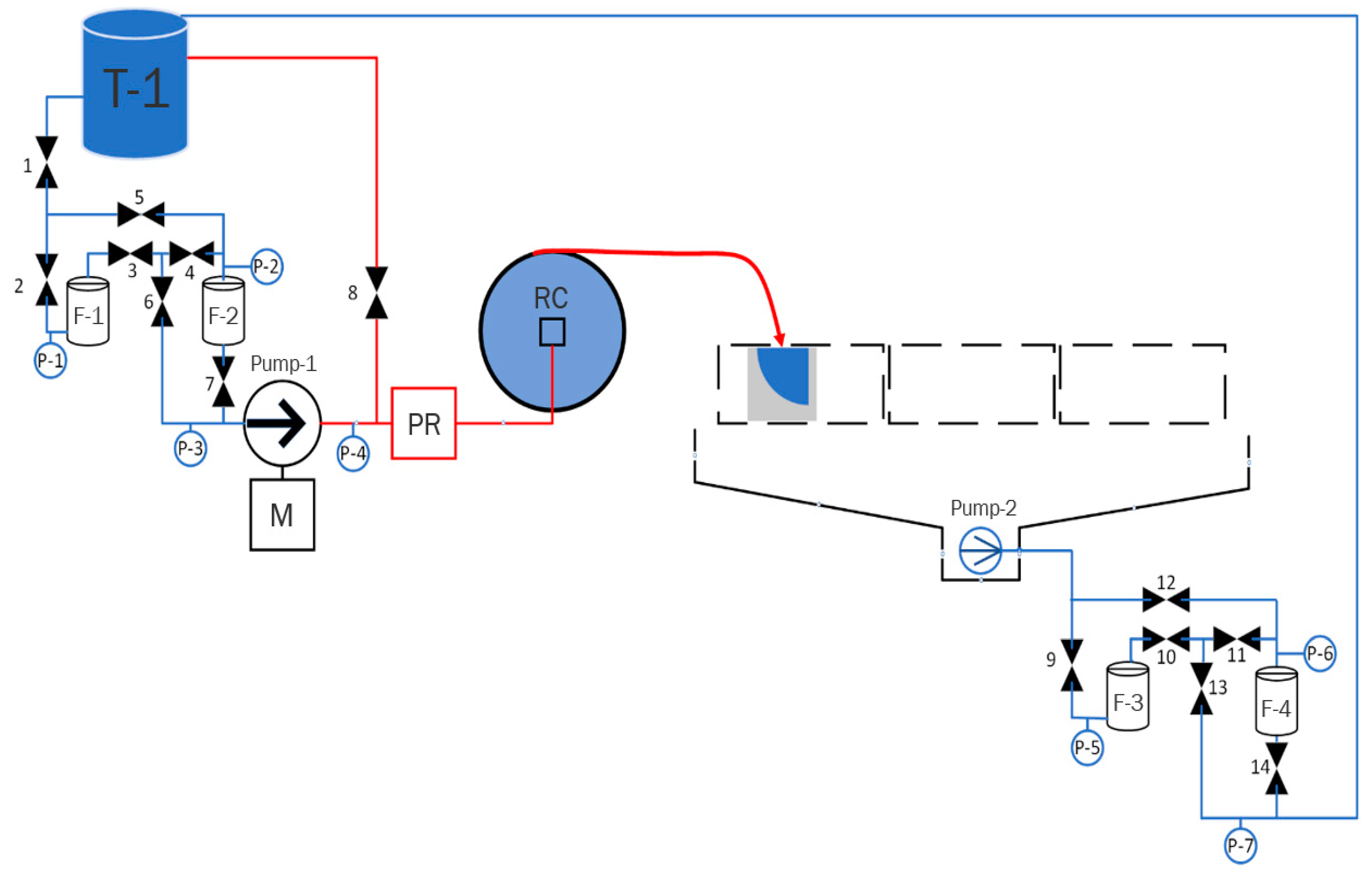
In order to solve this problem, full-scale modeling of the processes of drilling waterjet channels was carried out using a specially designed laboratory bench. The process flow diagram of the developed test bench is shown in Figure 3.
The flow diagram of the developed test bench (Figure 3) shows low-pressure pipelines and hoses in blue, and high-pressure sections in red. The high-pressure hydraulic laboratory bench operates as follows: the working disintegration agent is fed from the storage tank T-1 through ball valves 1 and 2 to the primary filtration unit consisting of two filters F-1 and F-2 installed in series. The letter designations “P” indicate pressure gauges. The rock disintegrating agent from the primary filtration unit is fed to the intake of Pump-1 high pressure pump. Pump-1 high-pressure pump is powered by a 35 hp M gasoline engine. Downstream of Pump-1 high-pressure pump, the working agent, passing through the pressure reducer PR and the rotary coupling RC, enters the high-pressure hose (shown in the flow diagram with a thick red line). The high-pressure hose delivers the working agent to the waterjet nozzle (shown in the figure with a red arrow). This way, the flow of the working agent stimulates the rock samples at a high velocity of jets, thus creating holes using the method of waterjet drilling. The spent working agent is collected in the bottom sump; Pump-2 (drain pump) pumps it through the spent working agent purification unit consisting of two mechanical purification filters F-3 and F-4 connected in series. Structurally, the spent working agent purification unit is similar to the primary filtration unit. Downstream of the spent working agent purification unit, the working agent is fed back to the storage tank T-1.
Table 1 shows technical characteristics of the main equipment and special tools used to create a laboratory high-pressure bench.
The experiments studied the technological process of waterjet drilling with 6 different through-type waterjet nozzles with an overall size of 18.3 × 31.3 mm, with different numbers and diameters of front and rear diffusers (holes). Table 2 shows the technical characteristics of the waterjet nozzles under consideration.
Modeling of radial channel drilling was carried out in aerated concrete blocks with density of 500 kg/m3 and strength between 25–32 kg/cm2.

3. Results

3.1. Results of Experiments for Drilling Radial Channels Using Waterjet Method in Laboratory Conditions under Static and Dynamic Stimulation Modes

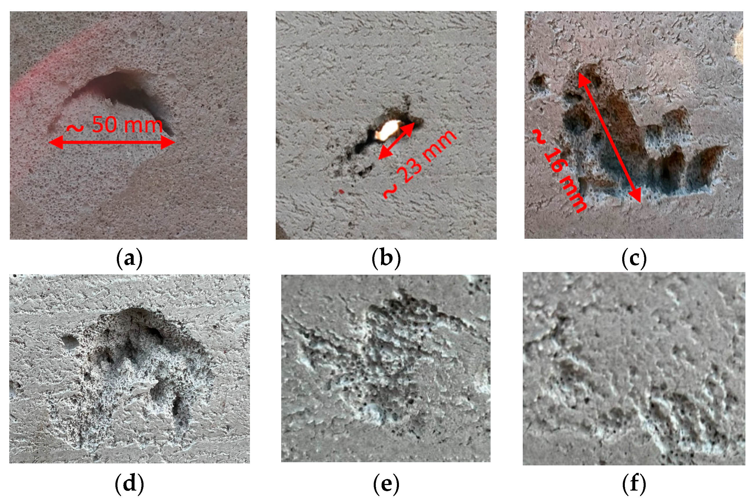
The first series of experiments was aimed at studying the process of specimen disintegration using different manufactured waterjet nozzles, whose characteristics are summarized in Table 2. The study mode was characterized as static, i.e., no control of the waterjet drilling process was performed by the operator. In this case, the waterjet nozzle is in direct contact with the disintegrating object in front of it. The first starting section of the pipeline was attached to the crushed object, simulating the previously created hydrodynamic channel in the rock. This approach, using an imitation of an already created channel, is also used in all subsequent experiments. All experiments of the first series were conducted for 10 min at a constant flow rate of the working agent (in this case, water) equal to 21 L/min. Figure 4 shows visual results of modeling the process of radial channel drilling using waterjet method under static mode.
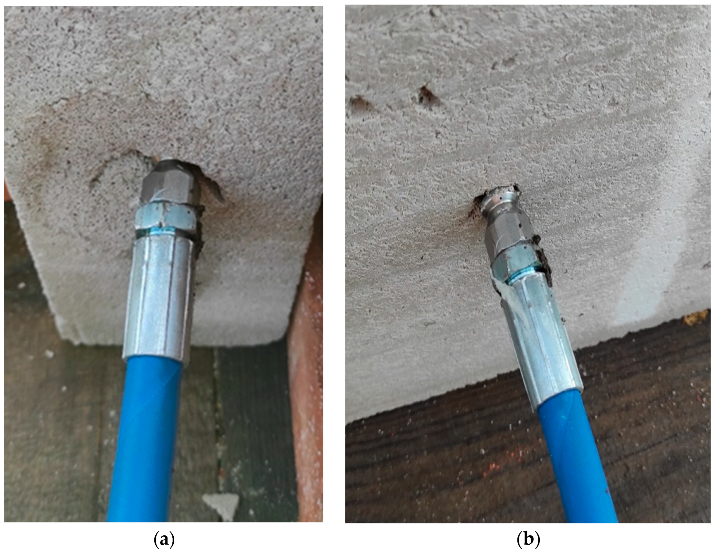
The second series of experiments was devoted to the study of dynamic stimulation of the disintegrating specimen, i.e., during the study, the waterjet nozzle performed forced linear reciprocating motion (with a constant periodicity, the waterjet nozzle was pulled 20 cm back and released to rush forward toward the disintegrating object). Thus, three experiments were carried out with a duration of 2 min, 5 min and 10 min, respectively. The studies were conducted with the use of waterjet nozzle No.1 at a constant flow rate of the working agent equal to 21 L/min. Figure 5 shows visual results of modeling the process of radial channel drilling by waterjet stimulation under dynamic mode.

3.2. Results of Determining the Optimal Values of Operating Parameters of Waterjet Nozzle Movement Speed along the Waterjet Channel Being Drilled

In [17], the authors conducted laboratory studies to determine the magnitude of the generated thrust force of the waterjet nozzle. In general, the question of thrust force is the most well-studied aspect of radial drilling technology, but the results of field tests studying the influence of radial channel size on the speed of the waterjet equipment assembly are still not published. The present study describes an experiment using a specially designed laboratory bench and additionally fabricated pipelines 11 m long with inner diameters of 106 mm, 62 mm, 48 mm and 38 mm, respectively. The first one-meter section of the pipelines under consideration was a starting section and was not taken into account when processing the results. In the course of the study, the passage velocity of the waterjet nozzle No.1 with the ratio of the area of the front diffuser to the total area of the rear diffusers equal to 0.33 (or 1 to 3) was measured for each of the considered pipeline sizes. Figure 6 shows the results of this experiment. It is worth noting that this experiment does not fully reflect and does not take into account the geometric features of the created channels, since in Section 3.1 triangular channels were obtained as a result of jet drilling. Nevertheless, when comparing the relative movement of the nozzle through channels of different diameters, there is a clear tendency to change the traction force. Based on the conducted experiment, numerical similarity can be used in the case of further use of the rotary nozzle type. In our case, we use a qualitative level of similarity and understanding of the results obtained from a mechanical point of view.
From the obtained results presented in Figure 4, the present authors can conclude that as the inner diameter of the channel through which the equipment assembly is propelled increases, the passage time increases, and, accordingly, the speed of movement of the waterjet nozzle decreases. In studying the process of movement of the waterjet nozzle through the pipeline with an internal diameter of 106 mm and at a flow rate of the working agent of 10.5 L/min, the movement of the equipment assembly was extremely slow.

4. Discussion of the Obtained Results

4.1. Peculiarities of Dynamic and Static Waterjet Stimulation

Based on the obtained results of the first series of experiments, it is concluded that the design of waterjet nozzles No.1 and No.2 allows for effective disintegration of the aerated concrete block sample—deep point channels were created, which facilitated making a through channel. However, the diameter of the created channel is not enough to fully accommodate the equipment assembly. This conclusion is explained by Figure 7.
In addition, based on Figure 4 the authors can conclude that increasing the number of diffusers on the front part of the waterjet nozzle helps increase the diameter of the created channel (coverage by waterjet drilling). However, this reduces the efficiency of the drilling process itself, as nozzles No.3 and No.4 do not create a through channel. Therefore, the authors assume that it is necessary to estimate the ratio of specific flow rate of the working agent to the unit of total area of both front and rear diffusers. Table 3 shows the calculation of the aforementioned specific flow rate of the working agent for the considered types of through-type waterjet nozzles.
Exact determination of the value of optimal specific flow rate of the working agent for different types of rock remains open and requires additional bench tests; however, given the current results, we can already make an unambiguous conclusion that it is necessary to consider this parameter in the design of waterjet nozzles, as well as to use at least three diffusers on the front surface of the nozzle to ensure effective waterjet coverage. Thus, for effective disintegration of aerated concrete blocks, the ratio of specific flow rate of working agent to the unit of total area of front and rear diffusers should tend to 26.75 L/(min-mm2).
Based on the results of the second series of experiments (Figure 3), the following conclusions are drawn:
  • The dynamic mode of stimulation appears to be much more effective and high-performing in comparison with the static mode, because over the same period of time, the dynamic mode of operation resulted in a waterjet channel through which the waterjet nozzle can be advanced further. When the back-and-forth motion is created, the rock is cut and abraded. Also, the presence of a constantly changing distance between the nozzle and the frontal wall of the created channel makes a significant effect in the destruction of the rock in front of itself. In the case of static impact, the hydromonitor nozzle is tightly pressed with the frontal part into the rock, which does not allow the front jets to cover a large cross-sectional area of the created channel. Thus, the required channel expansion does not occur so that the hydrodynamic nozzle can move forward and connect the rear jets to the channel expansion process.
  • Expansion of the waterjet channel is accomplished due to the effect of the rear jets of the nozzle. Similar results were also obtained and published in [7].

4.2. Results of Determining the Optimal Values of Operating Parameters Affecting the Speed of Movement of the Waterjet Nozzle along the Created Waterjet Channel

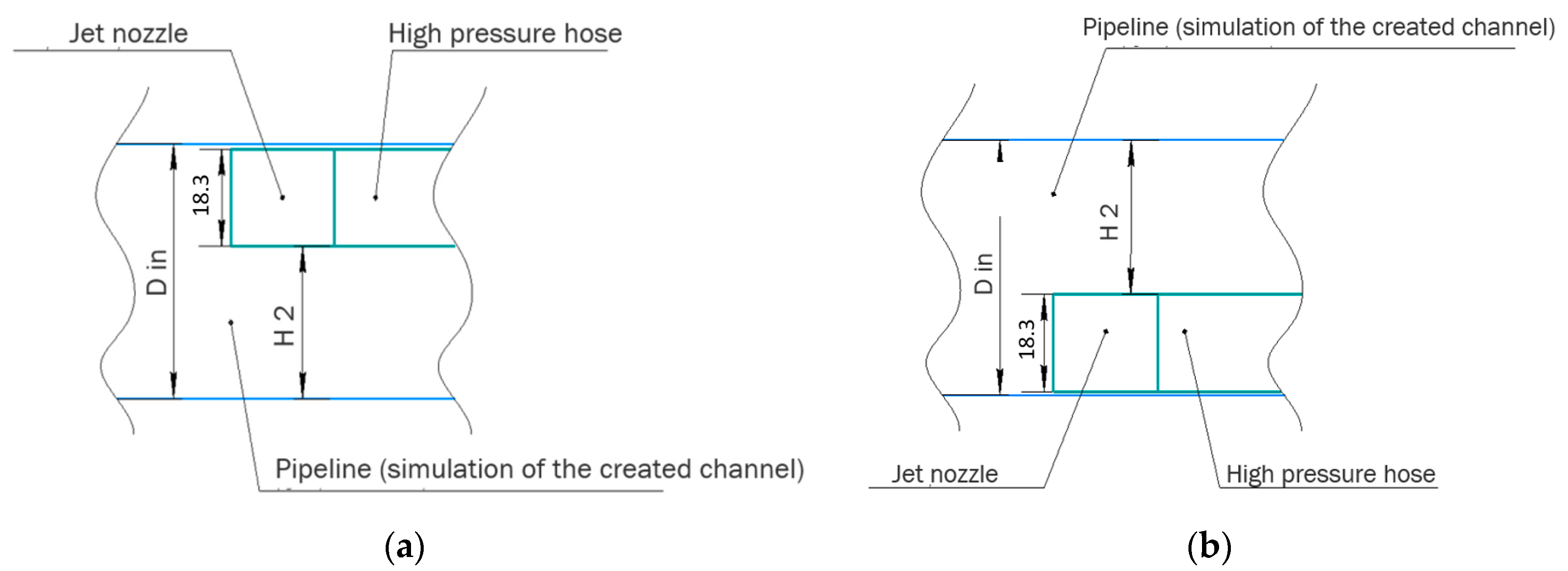
During this study, visual representation was made for spatial positioning of the waterjet nozzle during its movement through pipelines of different diameters; specifically, the waterjet nozzle was either pressed against the upper part of the pipeline (Figure 8a for the following modes of stimulation: Din = 38 mm and Q = 21 L/min; Din = 38 mm and Q = 10.5 L/min; Din = 48 mm and Q = 21 L/min; Din = 48 mm and Q = 10.5 L/min; Din = 62 mm and Q = 21 L/min) or against the bottom part (Figure 8b for the following modes of stimulation: Din = 62 mm and Q = 10.5 L/min; Din = 106 mm and Q = 10.5 L/min; Din = 106 mm and Q = 21 L/min). A schematic representation of this fact is shown in Figure 8.
Taking into account the spatial position of a waterjet nozzle in pipelines with different diameters, two technological coefficients were obtained according to the results of the conducted research: coefficient of the nominal position of the waterjet nozzle, which characterizes the position of the waterjet nozzle in the center of the created channel, and the coefficient of the actual position (Equations (1) and (2)), which provide a numerical estimation of the waterjet nozzle motion:
K n o m = 2 · D n o z z l e D i n D n o z z l e ,
K a c t u a l = 18.3 H 2 ,
where Knom—coefficient of the nominal position of the waterjet nozzle, which characterizes the position of the nozzle in the center of the created channel; Kactual—coefficient of the actual position of the waterjet nozzle during drilling; Dnozzle—nozzle outer diameter, mm; Din—inner diameter of the created radial channel; H2—actual value of deviation from the wall of the created radial channel, mm.
The proposed coefficients were calculated for the considered modes of study, the results of calculations are shown in Table 4.
The conducted study has shown that at mode No.3, the shortest time of passing the modeled section of the waterjet channel was recorded, and accordingly, the thrust force of the waterjet nozzle at this mode of stimulation was the greatest in the specified experimental conditions. The question of determining the optimal values of the proposed coefficients to ensure the most efficient process of waterjet drilling in different types of rock requires an additional in-depth study. However, even now can an unambiguous conclusion be drawn that under the experimental conditions it has been established that the highest efficiency is achieved with the following values of the proposed coefficients: Knom ≥ 1.86, Kactual ≥ 0.93.

5. Conclusions

The waterjet method of creating radial channels presents a promising technology for enhanced oil recovery. The existing equipment arrangements for radial drilling are characterized by low metal requirement, while the technological operations are time- and relatively cost-saving.
As a result of the conducted experiments, it was found that the dynamic mode of stimulation is more effective in comparison with the static mode. Thus, the development and introduction of additional modules to the equipment arrangement to provide constant forced linear-reciprocating motion of the waterjet nozzle will significantly increase the efficiency and speed of waterjet drilling.
As a result of the conducted bench tests, the optimal operating parameters were determined to achieve an effective process of waterjet channel creation under experimental conditions:
  • The optimum ratio of the number of front-to-rear diffusers (assuming they have the same diameter) is 1/3.
  • The permissible number of front diffusers is at least three.
  • The value of the specific flow rate of the working agent per unit of total area of the front and rear diffusers shall tend to 26.75 L/(min-mm2).
  • The proposed calculation coefficients should be within: Knom ≥ 1.86, Kactual ≥ 0.93.
In addition, on the basis of the obtained results, an assumption is made about the method of increasing the useful area of the created radial channel by using rotary-type waterjet nozzles (with rear diffusers rotating around the central axis). The questions of selecting the most effective modes of dynamic stimulation of rocks with different mechanical properties and studying the effectiveness of using rotary-type waterjet nozzles require additional research and bench tests, but the obtained results will allow to develop a methodology for selection of equipment arrangement and technological parameters of radial drilling for rocks with different mechanical properties.
As a result of the conducted research, the group of authors set the following task: to design and manufacture an underground equipment arrangement to ensure dynamic stimulation (constant forced linear reciprocating motion of the waterjet nozzle) taking into account the specified values of operating parameters.

Author Contributions

Conceptualization, S.K. and A.K.; methodology, A.K.; software, A.Y.; validation, A.K. and E.O.; formal analysis, S.K.; investigation, A.Y.; resources, A.K.; data curation, E.O.; writing—original draft preparation, S.K.; writing—review and editing, E.O.; visualization, A.Y.; supervision, A.K.; project administration, S.K.; funding acquisition, S.K. All authors have read and agreed to the published version of the manuscript.

Funding

The research was funded by the Ministry of Science and Higher Education of the Russian Federation (Project No. FSNM-2023-0005).

Institutional Review Board Statement

Not applicable.

Informed Consent Statement

Not applicable.

Data Availability Statement

The original contributions presented in the study are included in the article, further inquiries can be directed to the corresponding author.

Conflicts of Interest

The authors declare no conflict of interest.

References

  1. Chi, H.; Li, G.; Huang, Z.; Tian, S.; Song, X. Maximum drillable length of the radial horizontal micro-hole drilled with multiple high-pressure water jets. J. Nat. Gas Sci. Eng. 2015, 26, 1042–1049. [Google Scholar] [CrossRef]
  2. Huang, Z.; Huang, Z.; Su, Y.; Li, W.; Jiang, T. Where the laterals go? A feasible way for the trajectory measurement of radial jet drilling wells. In Proceedings of the SPE Asia Pacific Oil and Gas Conference and Exhibition, Brisbane, Australia, 23–25 October 2018. [Google Scholar] [CrossRef]
  3. Ibeh, S.; Obah, B.; Chibueze, S. Investigating the application of radial drilling technique for improved recovery in mature Niger delta oil fields. In Proceedings of the SPE Nigeria Annual International Conference and Exhibition, Lagos, Nigeria, 31 July 2017. [Google Scholar] [CrossRef]
  4. Ziaja, J.; Movchan, V. Pulling force simulation of jet bits in radial drilling technology. AGH Drill. Oil Gas 2016, 33, 417–424. [Google Scholar] [CrossRef]
  5. Salimzadeh, S.; Grandahl, M.; Medetbekova, M.; Nick, H.M. A novel radial jet drilling stimulation technique for enhancing heat recovery from fractured geothermal reservoirs. Renew. Energy 2019, 139, 395–409. [Google Scholar] [CrossRef]
  6. Bakin, D.A.; Popova, A.A. Jet drilling technology and its using in oil & gas industry. In Proceedings of the New Technologies for Oil and Gas Regions Conference, Tyumen, Russia, 26 May 2014. [Google Scholar]
  7. Cinelli, S.D.; Kamel, A.H. Novel technique to drill horizontal laterals revitalizes aging field. In Proceedings of the SPE/IADC Drilling Conference and Exhibition, Amsterdam, The Netherlands, 5–7 March 2013. [Google Scholar] [CrossRef]
  8. Ragab, A.M.S. Improving well productivity in an Egyptian oil field using radial drilling technique. J. Pet. Gas Eng. 2013, 4, 103–117. [Google Scholar] [CrossRef]
  9. Paveleva, O.N.; Popova, Z.S. Analysis of the effectiveness of the use of advanced technology for drilling deep radial channels at the Vakhitovskoye field. In Proceedings of the Geology and Oil and Gas Potential of the West Siberian Megabasin (Experience, Innovations), Tyumen, Russia, 24 November 2016. [Google Scholar]
  10. Jain, D.; Maut, P.P.; Saharia, P.; Dutta, R.; Yomdo, S.; Hatchell, I.; Mukherjee, A. Radial jet drilling in mature fields of Oil India Limited-an experimental approach. In Proceedings of the SPE Oil and Gas India Conference and Exhibition, Mumbai, India, 4–6 April 2017. [Google Scholar] [CrossRef]
  11. Medetbekova, M.; Christensen, H.F.; Amour, F.; Salimzadeh, S.; Nick, H.M. High pressure jet drilling effect in chalk and alteration of local geomechanics properties surrounding the radial hole. Int. J. Mech. Sci. 2021, 191, 105954. [Google Scholar] [CrossRef]
  12. Toczek, P.; Wisniowski, R.; Zlotkowski, A.; Teper, W. Hydraulic Radial Drilling Using a Rotary Hydraulic Nozzle Aimed at Increasing the Exploitation of Deposits. Energies 2023, 16, 7867. [Google Scholar]
  13. Medetbekova, M.K.; Christensen, H.F.; Salimzadeh, S.; Bakker, R.R.; Nick, H.M. Experimental investigation of drilling lateral boreholes in chalk rocks with high-pressure jets. Int. J. Geomech. 2020, 20, 04020049. [Google Scholar] [CrossRef]
  14. Novokreschennykh, D.V.; Raspopov, A.V. Prospects for the development of technologies for radial opening of the reservoir in the fields of the Perm Region. Oil Ind. 2014, 3, 54–57. [Google Scholar]
  15. Raspopov, A.V.; Kondratiev, S.A.; Novokreschennykh, D.V. Influence of geological and physical conditions on the efficiency of drilling radial channels into the near-well zone of the formation. Oil Ind. 2012, 3, 78–79. [Google Scholar]
  16. Huang, F.; Zhu, Z.; Wang, J.; Zhang, P.; Ren, Z.; Lu, J.; Su, H.; Zhang, H.; Li, J. Study on Energy Conversion Efficiency and Structure Optimization of the Multorifices Nozzle for Radial Jet Drilling. Geofluids 2023, 2023, 5517260. [Google Scholar] [CrossRef]
  17. Fu, B.; Zhang, S.; Liu, S.; Zhu, Z. Drilling performance analysis of a new type of direct-rotating mixed-jet nozzle. J. Pet. Sci. Eng. 2021, 200, 108302. [Google Scholar] [CrossRef]
  18. Li, J.; Dai, J.; Huang, Z.; Zhang, G.; Liu, X.; Li, H. Rock breaking characteristics of the self-rotating multi-orifice nozzle for sandstone radial jet drilling. Rock Mech. Rock Eng. 2021, 54, 5603–5615. [Google Scholar] [CrossRef]
  19. Meng, Q.; Liu, Y.; Qin, X.; Dou, Z.; Zhang, J.; Zhang, J.; Yang, G. Investigation on the Critical Flow Rate of Cuttings Transport in Coiled Tubing Sidetracking by Using a CFD-DEM Coupled Model. Arab. J. Sci. Eng. 2022, 48, 9311–9327. [Google Scholar] [CrossRef]
  20. Li, J.; Li, G.; Huang, Z.; Song, X.; Yang, R.; Peng, K. The self-propelled force model of a multi-orifice nozzle for radial jet drilling. J. Nat. Gas Sci. Eng. 2015, 24, 441–448. [Google Scholar] [CrossRef]
Figure 1. Schematic diagram displaying the working principle of the jet drilling.
Applsci 14 01149 g001
Figure 2. Specified types of nozzles: (a) through-type; (b) rotary type; (c) punch type.
Applsci 14 01149 g002
Figure 3. Process flow diagram of the developed test bench for modeling the processes of drilling waterjet channels: F-1—filter №1; F-2—filter №2; F-3—filter №3; F-4—filter №4; T-1—Tank; PR—pressure reducer; RC—rotary coupling; P-1–7—manometer.
Applsci 14 01149 g003
Figure 4. First series of experiments. Results of modeling the process of radial channel drilling under static waterjet stimulation using different through-type waterjet nozzles. (a) Nozzle No.1. (b) Nozzle No.2. (c) Nozzle No.3. (d) Nozzle No.4. (e) Nozzle No.5. (f) Nozzle No.6.
Applsci 14 01149 g004
Figure 5. Second series of experiments. Results of modeling the process of radial channel drilling under dynamic waterjet stimulation using different through-type waterjet nozzles: (a) dynamic stimulation for 2 min; (b) dynamic stimulation for 5 min; (c) dynamic stimulation for 10 min.
Applsci 14 01149 g005
Figure 6. Results of studying the effect of the size of the created radial channel on the speed of movement of the equipment assembly.
Applsci 14 01149 g006
Figure 7. Characteristics of created radial channels in static mode of waterjet stimulation: (a) when using waterjet nozzle No.1; (b) when using waterjet nozzle No.2.
Applsci 14 01149 g007
Figure 8. Schematic location of the waterjet nozzle captured during the experiment: Din—inner diameter; H2—actual value of deviation from the wall of the created radial channel.
Applsci 14 01149 g008
Table 1. Technical characteristics of the main equipment and special tools for a laboratory bench to model the processes of drilling waterjet channels.
Item on the Process Flow DiagramTechnical Characteristics
H-1Maximum throughput 1260 L/h (21 L/min)
Working pressure 480–500 bar
Gasoline engineMotor power 35 hp (25.74 kW)
Fuel consumption 3.8 L/h
Red line (high-pressure flexible hose)Hose length 100 m
Inner diameter DN, 8 mm
Outer diameter, 14.5 mm
Working pressure WP 600 bar
Burst pressure BP 2400 bar
Table 2. Technical characteristics of the waterjet nozzles under test.
Nozzle NumberImage of the Manufactured NozzleNozzle TypeNumber of Diffusers on the Front Part/Diameter of One Diffuser, mmNumber of Diffusers on the Rear Part/Diameter of One Diffuser, mmRatio of the Area of the Front Diffusers to the Rear Diffusers
No.1Applsci 14 01149 i001Through-type1/0.53/0.50.33 (3)
No.2Applsci 14 01149 i002Through-type1/0.53/1.00.083 (3)
No.3Applsci 14 01149 i003Through-type4/0.54/1.00.33 (3)
No.4Applsci 14 01149 i004Through-type4/0.56/1.00.16 (6)
No.5Applsci 14 01149 i005Through-type5/0.76/1.00.408 (3)
No.6Applsci 14 01149 i006Through-type5/0.76/1.20.283
Table 3. Values of the calculated specific flow rate of the working agent per unit of the total area of the front and rear diffusers for the tested waterjet nozzles.
Waterjet Nozzle Arrangement No.Number of Diffusers on the Front Part/Diameter of One Diffuser, mmNumber of Diffusers on the Rear Part/Diameter of One Diffuser, mmSpecific Flow Rate of the Working Agent Per Unit of Cumulative Area of Front and Rear Diffusers, L/(min × mm2)
11/0.53/0.526.75
21/0.53/1.08.23
34/0.54/1.05.35
44/0.56/1.03.82
55/0.76/1.03.17
65/0.76/1.22.41
Table 4. Results of calculations of the proposed coefficients and their correlation with the obtained results of waterjet nozzle velocity studies.
Mode No.Din, mmWorking Agent Flow Rate, L/minAverage Time of 10-m Section Passage, s K n o m K a c t u a l
148217.521.230.62
24810.59.551.230.62
338216.591.860.93
43810.58.361.860.93
5622110.840.840.42
66210.524.340.840.42
71062170.110.420.21
Disclaimer/Publisher’s Note: The statements, opinions and data contained in all publications are solely those of the individual author(s) and contributor(s) and not of MDPI and/or the editor(s). MDPI and/or the editor(s) disclaim responsibility for any injury to people or property resulting from any ideas, methods, instructions or products referred to in the content.