Article

Study of the Mechanical Performance of Grid-Reinforced Concrete Beams with Basalt Fiber-Reinforced Polymers

Centre for Innovative Structures, College of Civil Engineering, Nanjing Tech University, Nanjing 211816, China
*
Author to whom correspondence should be addressed.
Appl. Sci. 2024, 14(3), 1099; https://doi.org/10.3390/app14031099
Submission received: 23 November 2023 / Revised: 22 January 2024 / Accepted: 24 January 2024 / Published: 28 January 2024

Abstract

:
Basalt fiber-reinforced polymers (BFRPs) can reduce construction costs and mitigate corrosion-related issues associated with steel-reinforced concrete structures. There is limited research on completely substituting steel cages with composite material grid structures. Combining BFRP grids with concrete is an effective solution to address the issue of poor corrosion resistance; BFRP grids also have a good bond with steel-reinforced concrete. Therefore, this paper introduces a novel BFRP grid-reinforced concrete beam. Flexural tests indicate that grid frameworks with 3 mm and 5 mm thickness combined with concrete exhibit higher flexural load-bearing capacity. Shear tests show that the shear load-bearing capability is influenced by the shear span ratio. Shear load-bearing capacity decreases when the shear span ratio rises, but only up to a certain point. Theoretical calculations for grid-reinforced concrete beams are made to demonstrate good conformity with test values. Based on the research findings, design recommendations and precise measurements for the internal grid frameworks for composite material grid-reinforced concrete beams are provided.

1. Introduction

Fiber-reinforced polymer (FRP) composites are highly durable and possess exceptional tensile mechanical capabilities, even under extreme environmental circumstances. Fiber-reinforced plastic rods and sheets have been used more frequently since the 1990s to strengthen concrete structures in place of steel reinforcement. Compared to steel, FRP materials exhibit advantages such as excellent corrosion resistance [1,2,3], low weight, and high strength [4,5,6], but the stiffness, strength, and bond properties degrade at moderately elevated temperatures [7,8,9]. Both maritime engineering and bridge construction can make full use of them. Additionally, numerous studies have indicated that various types of fiber-reinforced polymers in dense concrete, such as FRP tubes and FRP wraps, can significantly enhance the mechanical properties mentioned above [10,11]. Manufacturers and researchers have been interested in basalt fiber-reinforced polymer (BFRP) as a new and dependable reinforcement material in recent years. Basalt fibers are produced from basalt rock, offering advantages including corrosion resistance [12,13,14] and high tensile strength [15,16,17]. Some basalt fiber products have already exceeded the tensile strength of glass fibers, with a superior elastic modulus compared to glass fibers [18,19]. Basalt fibers are derived from mineral ores, and their chemical composition is highly compatible with concrete, ensuring a good bond with the concrete material [20,21,22].
A matter of significant apprehension is the deterioration of buildings resulting from the corrosion of steel reinforcing. In order to tackle this issue, FRP rebars are frequently employed as an alternative to conventional steel and prestressed steel rebars. Feng et al. [23] reviewed and assessed established long-term durability prediction models for FRP rebars. Zhang et al. [24] examined the deterioration of the extended-term functionality of FRP rebars in maritime settings, assessed the longevity of FRP-reinforced steel-slag concrete buildings, and contrasted the effectiveness of various FRP rebars. FRP rebars provide superior tensile strength, enhanced corrosion resistance, reduced density, and a thermal expansion coefficient comparable to concrete, as opposed to traditional steel and prestressed steel. Studies and research on the durability of FRP rebars have been conducted. Lu et al. [25,26,27] conducted laboratory accelerated corrosion tests by wrapping BFRP rebars in a simulated seawater environment. Li et al. [28] examined the static and dynamic tensile characteristics of BFRP rebars and discovered that the tensile performance of BFRP rebars is extremely sensitive to strain rates. Dong et al. [29] developed hybrid beams with improved overall flexural performance by combining BFRP with ultra-high-performance concrete (UHPC). Hua et al. [30] used steel, BFRP, and glass fiber-reinforced polymer (GFRP) rebars to analyze performance, particularly crack development, during the service life of beams. Abed et al. [31] explored how adding several fiber types to concrete affects the flexural strength of beams made of BFRP reinforcement. Elgabbas et al. [32] conducted physical, mechanical, and durability tests on BFRP rebars. BFRP rebars possess poor alkali resistance as a result of problems with the resin–fiber interface, which significantly lowers their mechanical performance. BFRP rebars have inadequate alkali resistance due to issues with the resin–fiber interface, leading to a considerable reduction in their mechanical performance.
FRP reinforcement has a Young’s modulus that is lower than that of steel reinforcement. Consequently, concrete structures reinforced with FRP rebars often display a greater number of cracks and a higher degree of deformation compared to those reinforced with steel rebars. The combination of FRP rebars with concrete has posed persistent challenges in addressing the difficulties of rapid brittle failure and sliding of FRP rebars. Composite material grids are tension-dominant structures, characterized by being lightweight, high-strength, and possessing excellent load bearing, damage resistance, and impact resistance capabilities. When applied in ultra-high-performance concrete composite panels, they can significantly enhance the performance of the panels. Jia et al. [33,34] placed three layers of basalt fiber grids at different locations within concrete composite materials and studied their compression, splitting, tension, and beam bending performance. Ye et al. [35] designed and reported a novel FRP grid-reinforced UHPC composite panel, which is expected to exhibit superior durability and mechanical performance in harsh environments when optimized. Replacing steel structures with composite material grids and combining them with concrete is an effective solution to address the issue of poor corrosion resistance in steel-reinforced concrete.
Currently, the application of composite material grids focuses primarily on soil reinforcement and external repair and strengthening of steel-reinforced concrete beams. Research on fully replacing steel cages or FRP rebars with composite material grid structures is still relatively rare. In light of this, this paper introduces a novel structure known as the basalt fiber grid concrete composite beam, abbreviated as the grid concrete beam. The construction of this structure involves the utilization of basalt fiber grid sheets as the primary material. These sheets are cut and joined together to produce a framework with a grid-like pattern. This design mitigates issues related to corrosion that arise after concrete cracking and problems such as delamination and slippage in the reinforcement and repair of FRP plates, fiber fabrics, and laminates due to adhesive aging. Four-point bending tests were performed to investigate the impact of the thickness of the internal grid framework sheets on the flexural capacity of concrete beams with different types of grating. A shear performance test was performed to analyze how the thickness of the lower grid sheet and the side grid sheets affect the shear-bearing capacity of this type of beam. The design technique and methodology for the composite grating concrete beam are provided in this paper. The grid concrete beam exhibits a lightweight design, remarkable strength, and exceptional durability, making it a highly promising material for use in engineering applications.

2. Experimental Section

This study tested the flexural and shear capacities of the beams, as indicated by the diagrams below, in order to assess the mechanical performance of the suggested grid concrete beam.

2.1. Specimen Design

The flexural test was primarily controlled by three separate grid thicknesses: 1 mm, 3 mm, and 5 mm. As a result, two grid concrete beams were produced for each thickness, for a total of six simply supported rectangular beams. These beams were subjected to four-point flexural performance testing.
The research focus of this project was composite material grid concrete beams. The methodologies for designing reinforced concrete beams were followed in the design of the beam dimensions. For supported beams, the height-to-span ratio is generally within the range of 1/18 to 1/8, whereas the aspect ratio for rectangular section beams is typically between 2.0 and 3.5. During the design phase, attempts were made to maintain as many intact grid structures as feasible when cutting the composite material grid. This approach aimed to ensure more effective mechanical interlocking with the concrete particles and overall load-bearing capacity. Based on these considerations, the dimensions of the grid concrete beams were as follows: a length of 2050 mm and a cross-sectional size of 200 mm × 300 mm. Parameters of the test beams are shown in Table 1.
To investigate the shear performance of concrete beams with a composite grid, it is essential to ensure that the test beams do not experience bending failure due to insufficient resistance to bending before shear failure occurs. Therefore, in the design of the beams, considering the dimensions of the composite grid framework, the length of the beams for shear testing is smaller than that for bending tests. The final dimensions of the beams are 180 mm × 320 mm × 1250 mm. To separately investigate the contribution of the side grid strips to shear action, four sets of composite grid concrete beams are designed. The bottom grid strips in all four sets have a uniform thickness of 9 mm, whilst the side grid strips have thicknesses of 3 mm and 5 mm, respectively. In the remaining two sets of composite grid concrete beams, the bottom part employs two HRB400-grade steel bars with a diameter of 18 mm, while the side grid strips have thicknesses of 3 mm and 5 mm. The parameters of the test beams are shown in Table 2.
In collaboration with the Composite Materials Laboratory at Nanjing Tech University, specific experimental equipment and data acquisition tools were utilized. The loading apparatus employed for the tests was a 500-ton hydraulic testing machine. The cutting of basalt fiber grid plates was the first step in the preparation of composite material grid-reinforced concrete beams. Subsequently, the grid plates were organized, fixed, and secured using high-quality nylon straps, and then placed within molds for concrete casting.

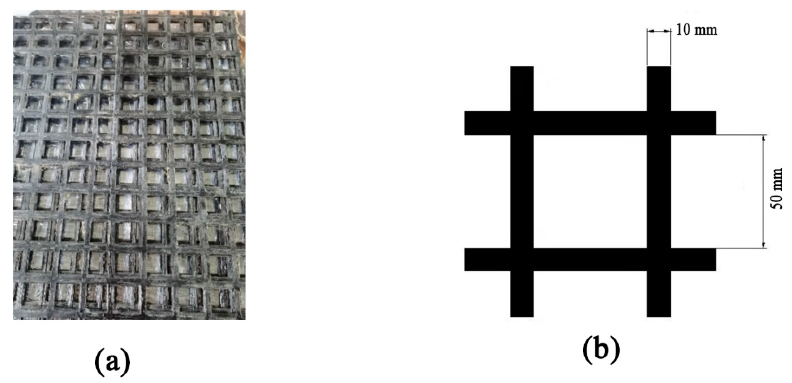
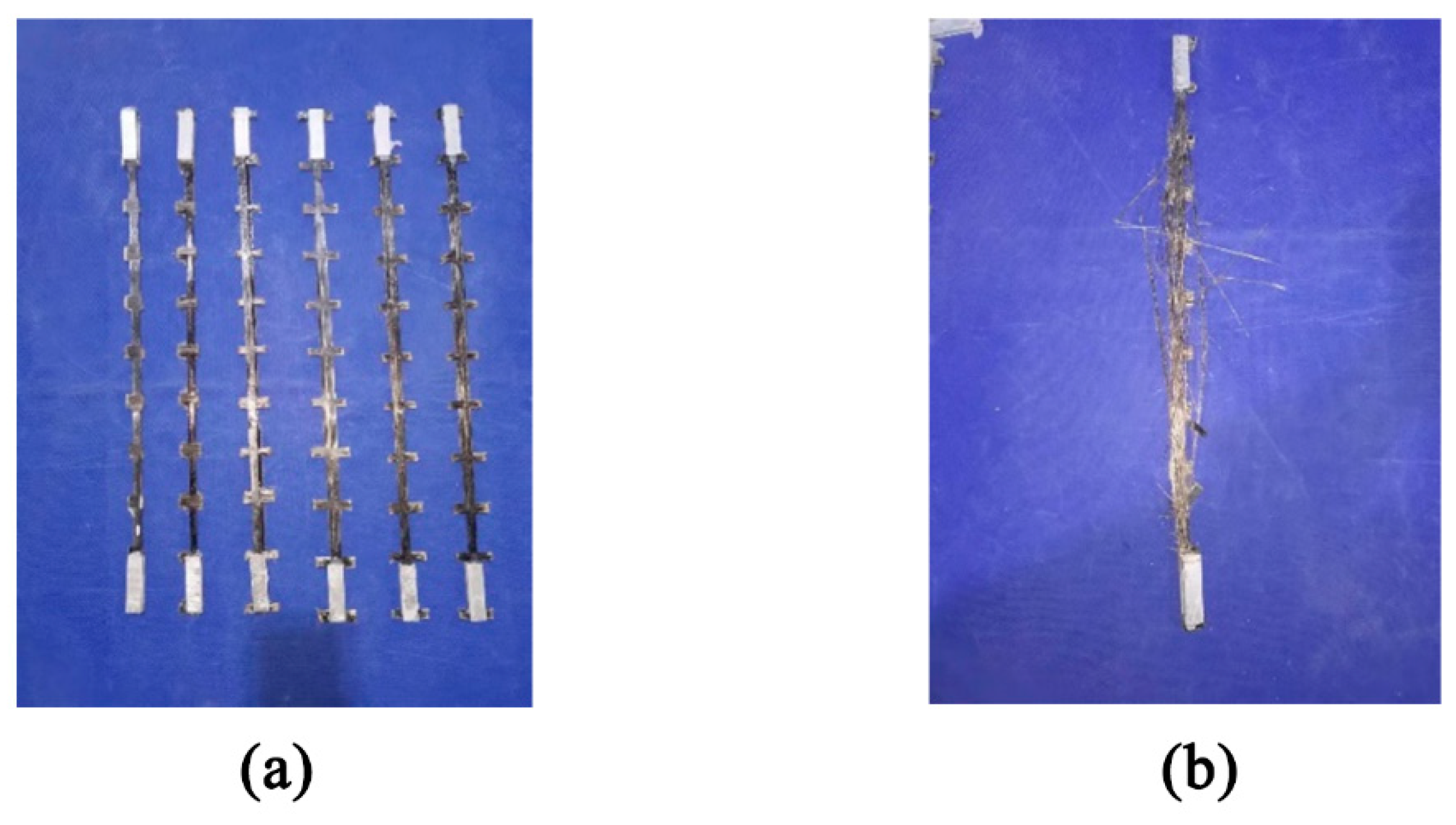
2.2. Material Properties

Concrete: The concrete used in this study was designed to have a compressive strength of C25. During the casting of the specimens, six standard cubic test blocks with dimensions of 150 mm × 150 mm were prepared according to the GB50152-2012 [36]. These reserved cubic specimens underwent standard material property tests, as illustrated in Figure 1. A hydraulic press was used to assess the compressive strength of the cubic test blocks. The material parameters of the concrete are shown in Table 3 below.
In accordance with the experimental measurements, the material properties of the composite grid bars are presented in Table 4.
The dimensions of the raw material for the grid are 720 mm × 2400 mm. The width of each strip in the grid is 5 mm, and the size of each grid in the pattern is 50 mm × 50 mm. The grid that was purchased was the final product manufactured from basalt fiber utilizing a German Karl Mayer warp knitting machine. This product is a semi-rigid material composed of basalt fiber. It is manufactured using the modern warp knitting technique, which creates a mesh structure as the basis material. Additionally, the product is coated on its surface. A physical image of the composite grid and local size annotations can be seen in Figure 2. Figure 3 displays a tensile test specimen of the composite grid.
The experimental use of HRB400-grade deformed steel reinforcement materials is based on data provided by the manufacturer, with a yield strength value of 401.5 MPa, ultimate tensile strength value of 542.1 MPa, and a modulus of elasticity of 202.4 GPa.

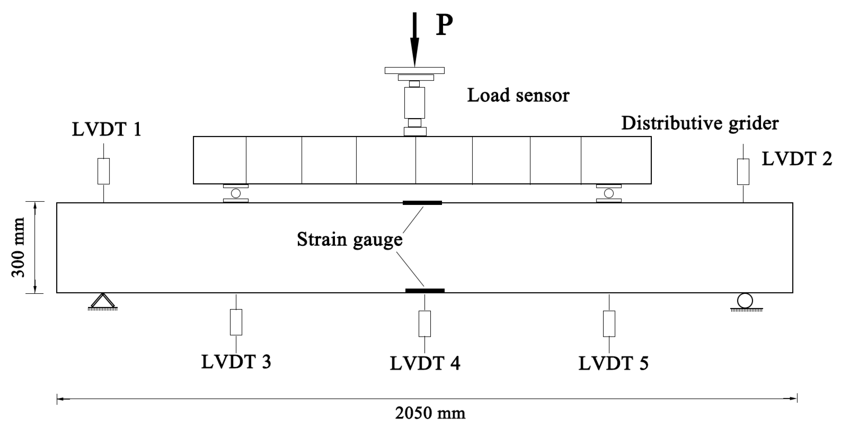
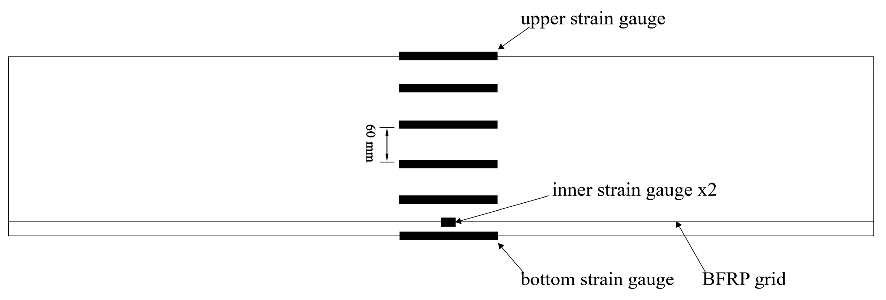
2.3. Test Setup and Instrumentation

The test beams are loaded in four-point bending tests, as seen in Figure 4. The two loading points are both located at a distance of 250 mm from the center of the span, and the calculated span is 1600 mm. All the tests on the beams were conducted in the Composite Material Structures Laboratory of Nanjing Tech University using a 500 t electro-hydraulic servo dynamic-static universal testing machine from Shenzhen Wance. Initially, the loading equipment is made to have full contact with the test beam and is ready for loading. A preload is applied to the test beams, which is set at 3 kN. Once the test beams meet the loading conditions, displacement-controlled loading is performed until the beams crack. The width and location of the cracks are recorded, and then the loading continues, with the loading rate increased to 0.4 mm/min. The loading is performed in stages, and the development trend of crack width and location is recorded for each stage until the test beams experience either tension or compression failure.
This experiment involves measuring the strain changes in the concrete beams by attaching resistance strain gauges to the surface. Vertical displacement gauges are also set up to monitor the deformation of the concrete beams. Inside each composite grid framework, to measure the strain of the lower tensioned grid bars, two short strain gauges (3 cm) are attached to the lower two grid ribs. Lightweight plastic tubes are used to shield the strain lines. On the surface of the concrete beams, four long strain gauges (10 cm) are attached with intervals of 50 mm to verify whether the beams conform to the assumption of a plane section. To detect the strain on the upper and lower surfaces of the beam at the midspan, strain gauges are also positioned on both the upper and lower sides of the concrete beams, as depicted in Figure 5.

3. Test Results

A structure that is different from the FRP concrete beam is designed after the bending-resistance test of six beams with a total thickness of three beams, and the test of cutting resistance. The theoretical calculation is carried out for this paper’s composite materials. In comparison with the test results, it is found that the extreme bearings of the composite beams can be predicted more accurately. Combining the above two parts of the experiment and the theoretical study of the bending-resistant bearing force, the design method for the composite material of the concrete beam is given for the interior of the beam.

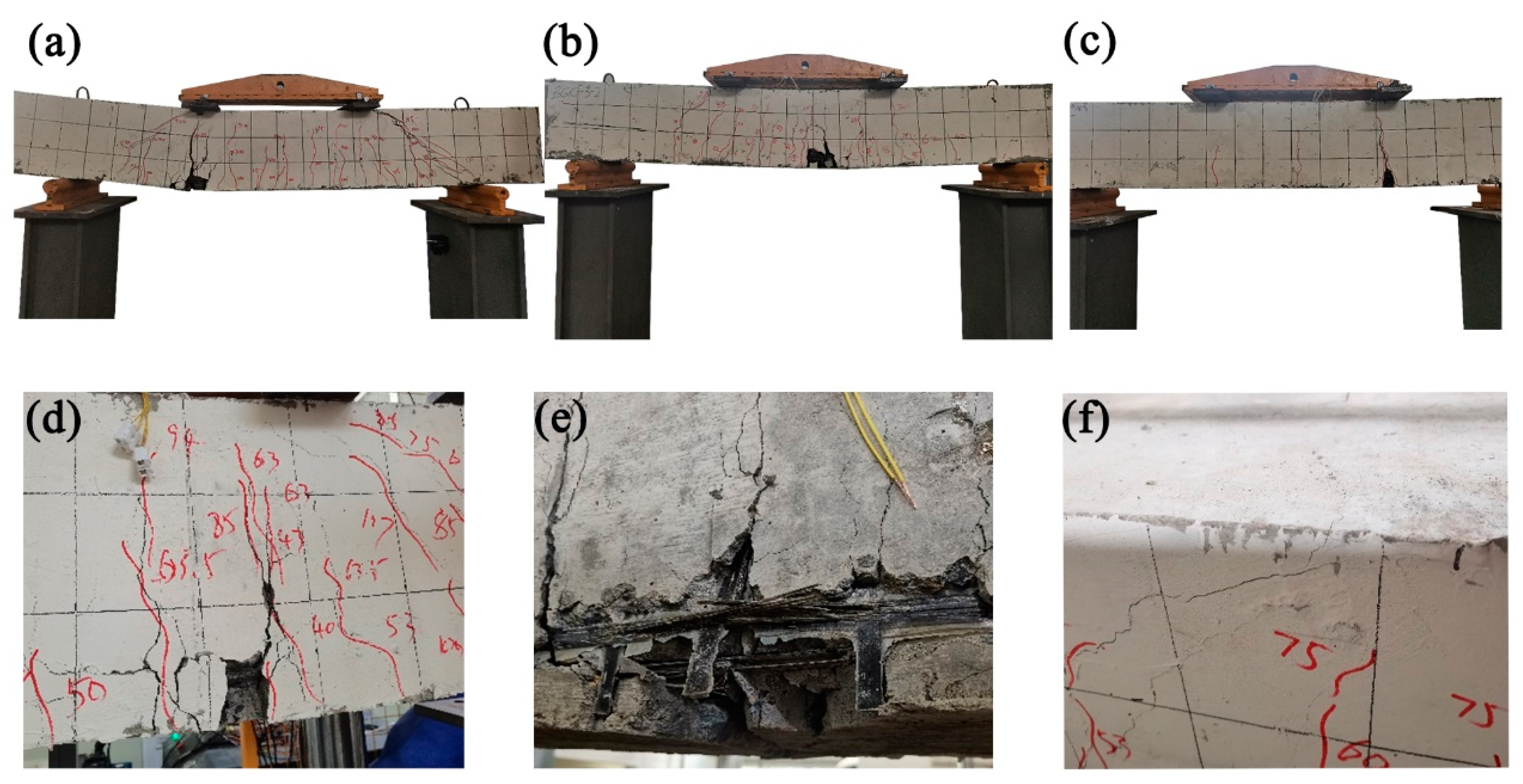
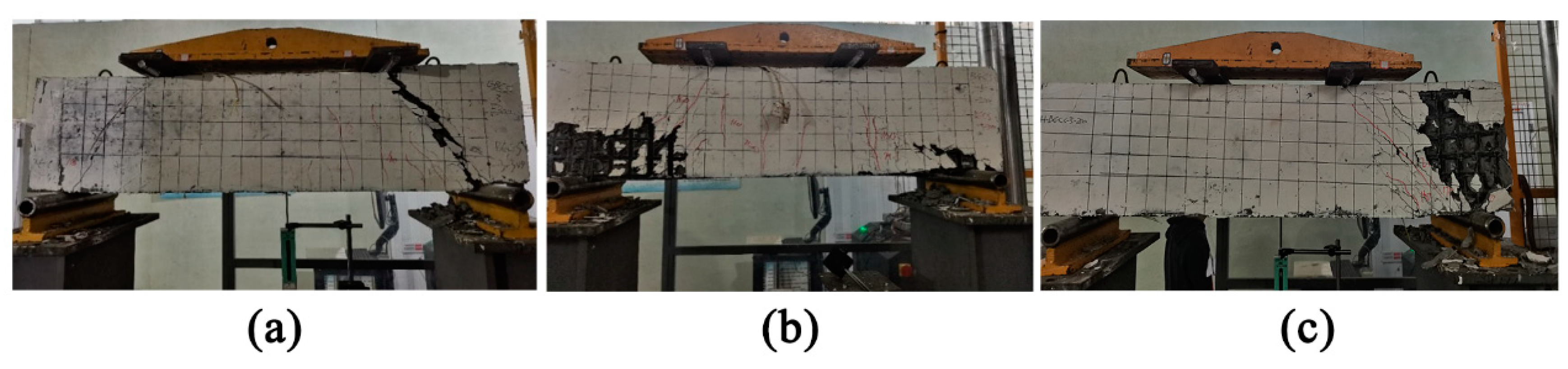
3.1. Visual Observation and Failure Modes

3.1.1. Bending Performance Test

Figure 6 depicts the experimental setting for the bending performance. Using specimen BGC-5-a as an example, the test beam’s cracks developed upward along the previous cracks when the load reached 35 kN. The specimen was damaged when the bearing capacity rapidly decreased, the test was ended, and the concrete at the bottom side of the loading end peeled off and broke when the force reached 141 kN, which is the maximum bending capacity.
Taking specimen BGC-3-a as an example, during the early stages of test loading, three cracks also appeared at the mid-span when the load reached 25 kN. When loading to 91 kN, about 100 mm on the right side of the mid-span (from the drawing grid plane as the datum plane), the BFRP grid broke, the specimen was damaged, and the loading ended.
There is a great difference between the test phenomenon of specimen BGC-1-a/b and the test beams of BGC-5-a/b and BGC-3-a/b. After the micro-cracks appeared, the test beam made a loud tearing sound of the BFRP grating. At this time, the displacement value on the hydraulic press display increased rapidly, and the load was between 35 kN and 40 kN. The left and right sides were even, and the machine was braked urgently for safety reasons. The test was stopped.

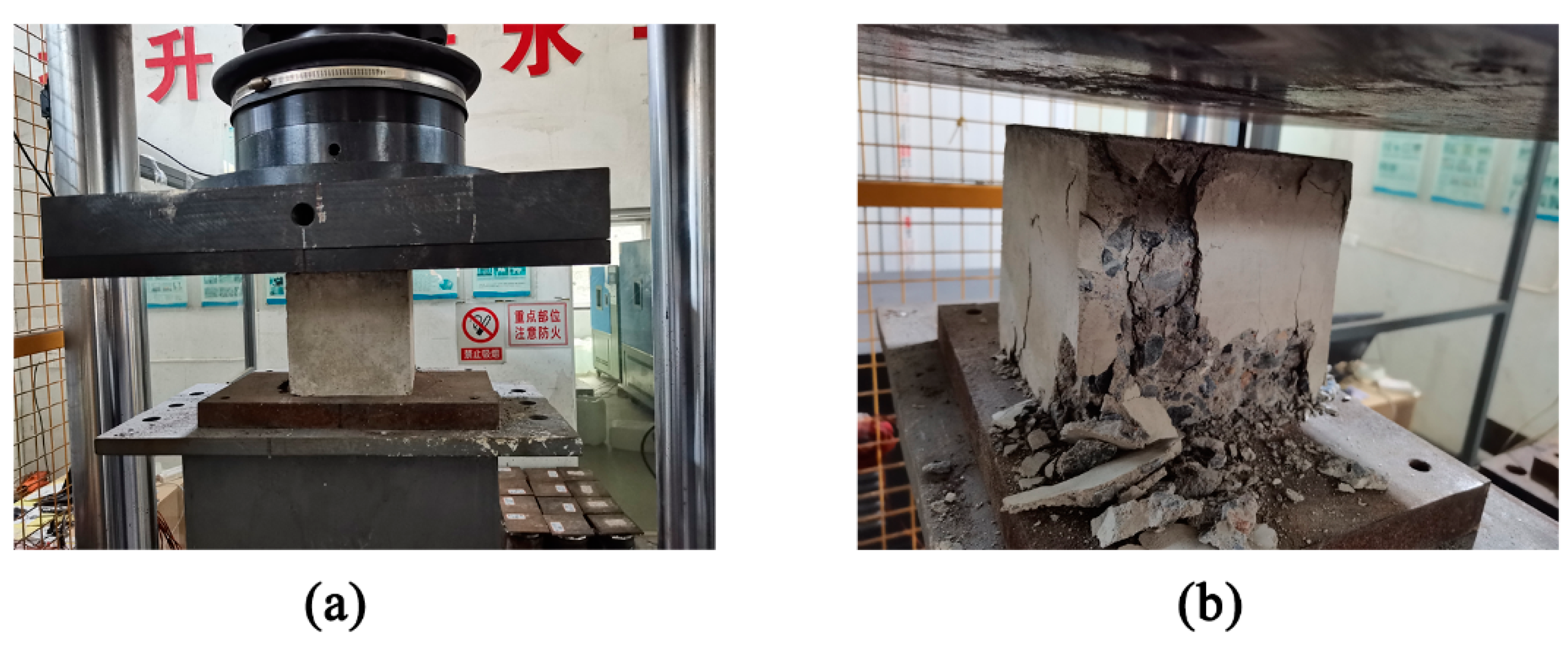
3.1.2. Shear Performance Testing

The shear test parameters encompass the shear span ratio, the thickness of the composite material grid, and a comparison between using a composite material grid or steel at the bottom.
For this test, four sets of composite material grid concrete beams were used. The bottom grid strips were 9 mm thick, and the side grid strips were 3 mm and 5 mm thick. The side grid strips’ role in shear resistance was thoroughly investigated. Two HRB400 steel bars with an 18 mm diameter were utilized at the bottom of the remaining two sets of composite material grid concrete beams.
During the preparation of the composite material grid framework, the dimensions of the framework were 150 mm × 320 mm × 1250 mm, and the binding process was the same as the one used in the bending test for the beam. In the case of the HBGCS-3 and HBGCS-5 beams, two HRB400 steel bars were used at the bottom to replace the composite material grid strips.
Strain gauges were affixed at two distinct positions to monitor the tensile strain of the bottom composite material grid strips/steel bars and the strain of the side grid strips during the shear test.
As shown in Figure 7, for BGCS-3-a and BGCS-3-b, the test beam shear span ratios were 0.8 and 1.16, respectively, and the side grid thickness was 3 mm. A vertical crack with a height of 35.2 mm developed at the base of the test beam’s pure bending section when the test load reached 83 kN. When the load reached 193.3 kN, the concrete on the test beam’s upper and lower surfaces was crushed, producing a loud breaking sound of the BFRP grating strips, and the test beam experienced shear compression failure. At the same time, the test beam produced a tearing sound of BFRP and concrete spalling appeared on the surface.
The test beams for BGCS-5-a and BGCS-5-b had shear span ratios of 0.8 and 1.16, respectively, and the side grid sheet thickness was 5 mm. The test beam’s pure bending section experienced its first vertical crack, measuring 36 mm in height, when the test force hit 79.1 kN. The BFRP grating began to rip at a higher volume when the force reached 270 kN, and the test beam sheared.
The side grid sheet thicknesses for HBGCS-3 and HBGCS-5 were 3 mm and 5 mm, respectively, and the shear span ratio was 1.16. The composite grid was replaced at the bottom with two HRB400 steel bars. Since steel bars were used at the bottom end of the test beam instead of a composite grid, the test beam clearly yielded during the loading phase. The load value on the hydraulic testing equipment started to drop when the 220 kN peak load was attained. The two test beams failed by barometric failure when the load reached 110 kN and the concrete at the support fell.

3.2. Load-Displacement Curves

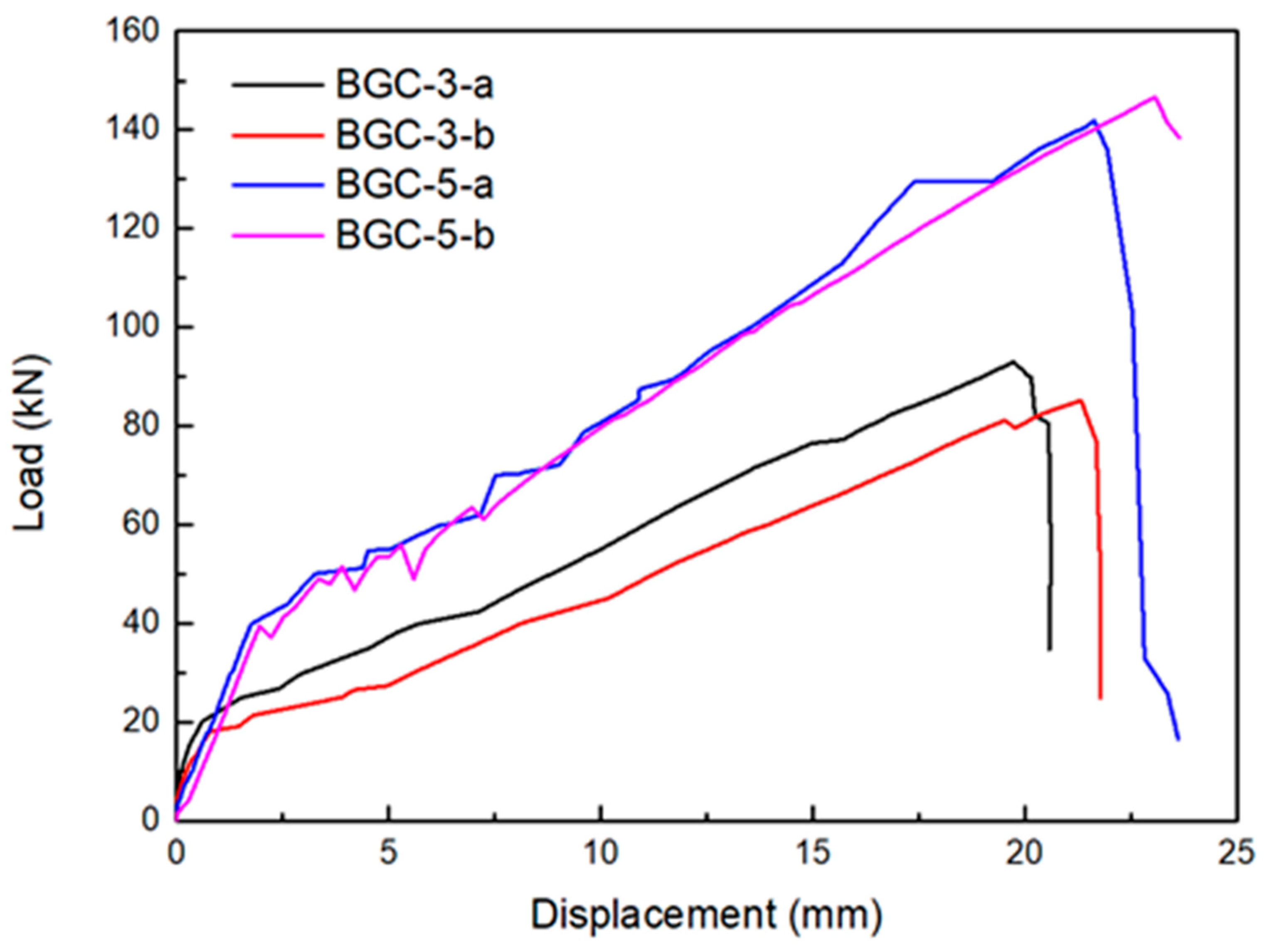
3.2.1. Bending Performance Curves

The primary test results are displayed in Table 5, where Ny represents the cracking load of the grid beam, Nu represents the ultimate flexural load of the grid beam, and ΣNu/2 is the average of the test results for the identical beams.
Below are the load-displacement curves for the four test beams, two of which are BGC-5 and two BGC-3. To examine the effects of various grid thicknesses on the cracking load and ultimate flexural load of the beams, the BGC-1-a/b group employed grid bars of minimal thickness and exceptionally poor tensile bearing capacity, resulting in the test beams of this group exhibiting behavior that was practically identical to that of plain concrete beams. Consequently, the data was stored, but the load-displacement curves were not graphed.
The load–displacement relationship of the grid concrete beams exhibits linearity before the occurrence of cracking in the tensile zone of the concrete, as seen in Figure 8. The slopes of the curves for beams made of 3 mm-thick and 5 mm-thick grids are identical. Both sets of test beams exhibit a noticeable decrease in stiffness in their load-displacement curves after the concrete in the tensile zone cracks and leaves the load-bearing area, indicating a considerable fall in the slope of the load-displacement curve during this period.
It is evident that the BGC-5 group of test beams has noticeably higher slope and peak load values than the BGC-3 group at this point, when the concrete in the tensile zone stops carrying a load and the bottom tensile composite grid takes over. This suggests that the ultimate flexural strength, stiffness, and cracking load of the grid concrete beams are all significantly impacted by an increase in grid thickness. Calculations show that adding 2 mm to the grid thickness increases the composite grid concrete beams’ ultimate flexural strength by an average of 61% and their average cracking load by an average of 110%.
The average maximum deflection of the BGC-5 group is 17.1% higher than that of the BGC-3 group, according to the maximum deflection statistical comparison. The reason for this variation is due to the manufacturing process of the composite grid itself, which leads to unavoidable thickness differences in the 3 mm thick grid bars among different grid thicknesses. The load-displacement curves for the 3 mm thick and 5 mm thick grid beams were differing at the concrete cracking stage in the tensile zone. This occurred mostly because the preload changed during testing, which caused the load-displacement curves to be different before cracking.

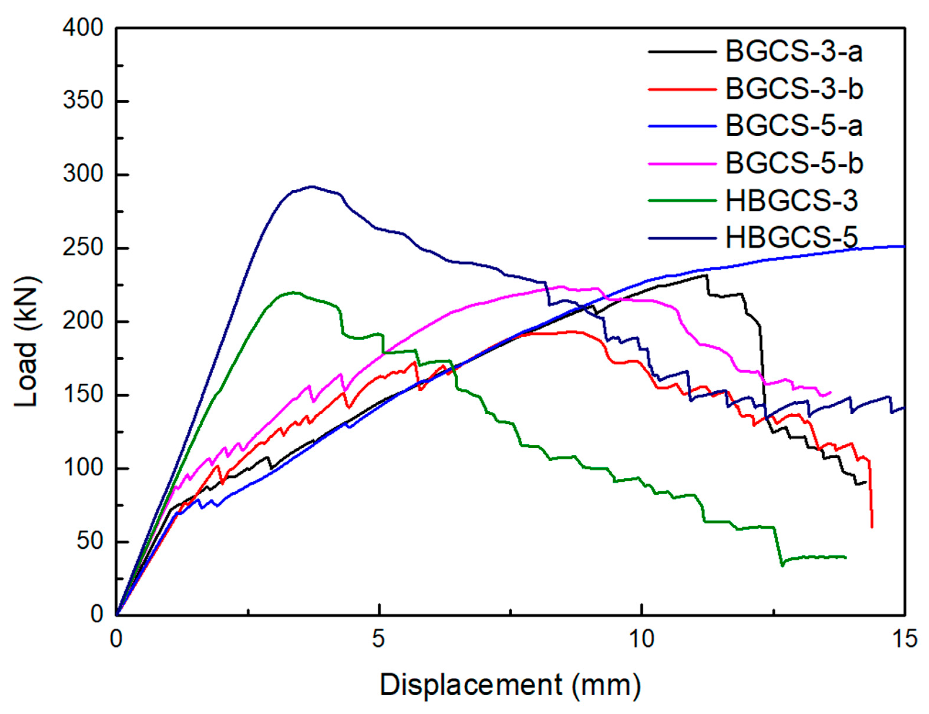
3.2.2. Shear Performance Curves

This section provides the load-displacement curves of the shear capacity tests for the composite material grid-reinforced concrete beams. The curves are then compared among various test beams. Figure 9 presents the load-displacement curves for every test beam. The crack distribution of BFRP-grid beams is shown in Table 6.
In the shear capacity tests of composite material grid-reinforced concrete beams, neither the side grid bars nor the bottom grid bars exhibit significant strains during the initial loading phase prior to the concrete cracking, based on the strain data of the internal grid bars in each group of beams. When loaded to the point of cracking, the bottom composite material grid bars exhibit a noticeable increase in strain. However, the side grid bars only exhibit a notable increase in strain when inclined fractures emerge under greater weights. Simultaneously, when comparing the concrete beam reinforced with steel bars in the lower section to the beam solely composed of composite material grid sheets, it is evident that under identical load conditions, the strain experienced by the steel bars is lower than that of the composite material grid strips at the bottom. This discrepancy arises due to the properties of the composite material grid. This phenomenon arises due to the fact that the elastic modulus of the sheet is comparatively lower than that of the steel bars employed in this experiment.

3.2.3. Discussion of Bending Performance

Following the comparison, three similarities between the load-displacement curves of basalt fiber-reinforced sea-sand concrete beams and BFRP grid-reinforced beams are found:
(1) Both kinds of beams’ load-displacement curves have two segments, each of which represents a different behavioral stage. At first, the relationship between load and displacement is linear. The grid-reinforced concrete beam cracks at the point of inflection on the load-displacement curve, which causes a large drop in stiffness. Following cracking, the lower concrete component begins to break, and the curve’s slope becomes much steeper than it was in the earlier stage.
(2) The load-displacement curves display a two-stage linear relationship. Before the tensile zone concrete starts to fail, the concrete is in an elastic stage. After the tensile zone concrete reaches its cracking strain, the tensile zone concrete fails, and the tensile forces are transferred to the composite material grid. Composite materials react linearly under stress because of their innate linear elastic characteristics.
(3) Brittle failure: After reaching their peak, the load-bearing capacity curves of BFRP grid-reinforced concrete beams show an abrupt decline. Grid-reinforced beams with 3 mm and 1 mm thickness exhibit bottom grid bar rupture. In the case of the 5 mm thick grid-reinforced beam, local crushing of the upper concrete occurs, and the bottom grid bars rupture.

3.2.4. Discussion of Bending Performance

In summary, the analysis of the shear behavior of composite material grid-reinforced concrete beams may be derived from the experimental results and load-displacement curves obtained from the preceding two sections.
(1) Crack Development:
Based on the test findings of different beams, it was found that the pure bending portion of the beams for the BGCS-3-a and BGCS-3-b groups had vertical cracks. Both beams experienced diagonal cracks along the loading points to the support end, occurring at 186 kN and 170 kN, respectively. The first diagonal crack was surrounded by parallel diagonal cracks as the load rose, and the vertical cracks in the pure bending portion stayed at a constant height until collapse. In contrast, BGCS-5-a/b and HBGCS-3/5 exhibited a different crack development pattern. Initially, no obvious cracks appeared, and there were no significant vertical cracks in the pure bending section. The initial rigidity of these beams was higher, and the strain on the hydraulic machine grew quickly. Later, diagonal cracks that ran from the loading point to the support end started to show. Dense parallel diagonal cracks around the original diagonal crack appeared with further loading.
(2) Influence of Side Grid Thickness on Shear Capacity:
Comparing the results, BGCS-5-a had a 28% higher ultimate shear capacity compared to BGCS-3-a, BGCS-5-b had a 35% higher ultimate shear capacity compared to BGCS-3-b, and HBGCS-5 had a 32% higher ultimate shear capacity compared to HBGCS-3.
(3) Influence of Shear Span Ratio on Ultimate Shear Capacity:
To compare the impact of shear span ratio, under the same side grid thickness conditions, when comparing BGCS-3-a and BGCS-5-b, the former had a 19.9% greater ultimate shear capacity, and the latter had a 12.4% higher ultimate shear capacity. The findings showed that the composite grid-reinforced concrete beams’ ultimate shear capacity decreases as the shear span ratio increases.
(4) Comparison of Bottom Tensile Part with Steel Reinforcement:
The bottom part of HBGCS was made of HRB400 steel bars, and the grid material for BGCS was basalt fiber composite. The tests showed that when the side grid thickness and shear span ratio were kept the same, BGCS-3-a and HBGCS-3 had ultimate shear capacities of 231.71 kN and 219.89 kN, respectively. BGCS-5-a and HBGCS-5 had ultimate shear capacities of 251.93 kN and 291.90 kN, respectively. The side grid thickness had a more pronounced effect on ultimate shear capacity compared to the material used in the bottom tensile part.
As a result, these observations and comparisons provide valuable insights into the behavior and performance of composite material grid-reinforced concrete beams under shear loading. The shear performance of these beams is influenced by the presence of vertical and diagonal cracks, the thickness of the side grid, the shear span ratio, and the role of the bottom tensile component (composite grid or steel reinforcement).

3.3. Design Methods of Load-Bearing Capacity

3.3.1. Design Methods of Flexural Bearing Capacity

The American Concrete Institute (ACI) 440 series of standards are currently among the main reference design codes used in research and construction work related to building structures using fiber-reinforced composite materials. ACI 440.1R is one of the standards that provide instructions for designing and building non-prestressed FRP reinforced concrete structures. This paper will primarily discuss and reference ACI 440.1R-06 [37].
FRP reinforcement does not have a yield strength. The formula for calculating the balanced reinforcement ratio for design tensile strength is as follows:
ρ f b = f c f f u E f ε c u E f ε c u + f f u
When ρ f ρ f b ,
M n = A f f f ( d a 2 )
f f = E f ε c u β 1 d a a
a = A f f f 0.85 f c b
When ρ f ρ f b ,
M n = A f f f u ( d β 1 c b 2 )
c b = ( ε c u ε c u + ε f u ) d
A f , min = 4.9 f c f f u b w d 330 f f u b w d
where ρ f b is the FRP balanced reinforcement ratio, f c is the specified compressive strength of concrete, MPa; f f u is the design tensile strength of FRP, considering reductions for service environment, MPa; E f is the design or guaranteed modulus of elasticity of FRP defined as mean modulus of sample of test specimens, MPa; ε c u is the ultimate strain in concrete strain conditions; ρ f is the FRP reinforcement ratio; M n is the nominal moment capacity; f f is the stress in FRP reinforcement in tension, MPa; A f is the area of FRP reinforcement, mm 2 ; d is the distance from extreme compression fiber to centroid of tension reinforcement, mm; a is the depth of equivalent rectangular stress block, mm; f c is the specified compressive strength of concrete, Mpa; β 1 is the factor taken as 0.85 for concrete strength up to and including 28 Mpa; c b is the distance from extreme compression fiber to neutral axis at balanced strain condition, mm; f c is the square root of specified compressive strength of concrete, Mpa; and b w is the width of the web, mm.
When calculating the reinforcement ratio for FRP-reinforced concrete beams, the cross-sectional area of the upper compression and lower tensile FRP reinforcement materials is the primary factor taken into account. The primary structural elements that play a role in the beam are the grid bars. As a result, while calculating the reinforcement ratio, the cross-sectional area of the BFRP grid bars must be considered. According to the method for calculating the reinforcement ratio for FRP-reinforced concrete beams, the reinforcement ratio for composite concrete beams with three different grid thicknesses is ρ f = A f b h 0 f , as shown in Table 7.
Based on the experimental observations, the test beams in both the BGC-5 and BGC-3 groups exhibited failure characterized by the rupture of the bottom composite material grid strips. Additionally, calculations have shown that the reinforcement ratios for both sets of test beams are below the specified limit reinforcement ratio. Therefore, calculations will be conducted as M n = A f f f u ( h 0 f β 1 c b 2 ) .
After performing the calculations, Table 8 provides a comparison between the ultimate flexural load capacity values computed using the American ACI standards and the experimental results.
Both the BGC-5 group and BGC-3 group ultimately experienced the tearing of the lower composite material grid bars. The flexural load capacity in this paper was primarily determined by the grid bars. The experiments conducted in this article consistently showed that the failure mode of all the test beams was the rupture of the bottom grid bars, with no instances of the bottom grid bars remaining intact while the upper concrete was crushed. Therefore, the following formula is given:
M A f f f u ( h 0 f β 1 c b 2 ) + λ f f c A f k n k n h k n
k = l k h 0 x b
where k is the proportion of the side grid’s contribution to bending resistance according to the assumption of a flat section, h 0 is the distance between the bottom grid resultant point and the edge of the upper pressure zone, A f k is the area of the grid, λ is the loss coefficient caused by the grid manufacturing process, and x b is the boundary pressure zone height.

3.3.2. Design Methods for Shear-Bearing Capacity

Currently, the generally accepted method for calculating the shear capacity of FRP-reinforced concrete beams is mainly composed of two parts: one part is the shear capacity contributed by concrete V c , and the other part is the shear capacity contributed by stirrups V f .
V = V c + V f
The calculation method of the shear-bearing capacity contributed by stirrups in the ACI 440.1R-06 can be calculated according to the following calculation formula:
V f = A f σ f h 0 f s
σ f = E f ε f
where V c is the nominal shear strength provided by concrete, V f is the shear resistance provided by FRP stirrups, h 0 is the effective height of FRP reinforced concrete beam, s is the stirrup spacing or pitch of continuous spirals, σ f is the allowable tensile stress in FRP reinforcement, E f is the stirrup elastic modulus, and ε f is the strain in FRP reinforcement.
In the ACI 440.1R-06, the calculation method for the shear force borne by the concrete part is as follows:
V c = 2 5 f c b w k d
k = 2 n f ρ f + ( n f ρ f ) 2 n f ρ f
n = E f E c
ρ f = A f l / b w h 0
where b w is the width of the web, d is the distance from extreme compression fiber to centroid of tension reinforcement, E c is the modulus of elasticity of concrete, n f is the ratio of modulus of elasticity of FRP bars to the modulus of elasticity of concrete, ρ f is the FRP reinforcement ratio, and A f l is the area of FRP reinforcement. Table 9 provides a comparison between the shear cracking load capacity values computed using the American ACI standards and the experimental results.

3.3.3. Design Method for BFRP Grid-Reinforced Concrete Beams

Taking a general rectangular cross-section beam as an example, it is assumed that the size of the beam is given, the length of the beam is l , the width and height of the normal section of the beam are a and h , the height of the bottom protective layer of the beam is b h , and the thickness of the side protective layer is b c .
The size of the grid in composite material grid panels is a critical dimensional parameter. In order to ensure the maximum particle size of the coarse aggregates used in the concrete, the grid size of grid panels made of composite materials cannot be smaller.
l w = b h
The length of the longitudinal grid bars along the longitudinal length of the beam, whether it is a horizontal or vertical grid panel, should match the length of the beam overall.
l z = l
The width of the horizontal grid panel should match the width of the beam less the thickness of the side protective layer, and the length of the longitudinal grid bars should equal the height of the beam, as a 2 b c .
To guarantee the stability of the grid framework and prevent damage during pouring, the optimal spacing for the rectangular grid-shaping material is between 200 mm and 350 mm.
Using a typical concrete beam as an example, its dimensions are 200 mm × 300 mm in cross-section, and it has a 2500 mm overall length. The concrete grade utilized for the beam is C30. The beam employs a composite material grid framework using basalt fiber composite grid panels. The grid framework consists of four parts, which are two side composite material grid panels, the bottom composite material grid panel, and the grid panels used for shaping and fixing. The composite material grid panels are made of the same materials as are utilized in this paper. The precise parameters are in Table 10:
The 50 mm × 50 mm grid size of the composite material grid panel is developed for ease of pouring and cutting, based on the beam dimensions and particle grading in actual engineering applications. Taking a side protection layer width of 25 mm, it can be calculated that there should be four longitudinal grid bars at the bottom. The arrangement of the grid framework involves binding the lowest longitudinal distributed grid bars on the side grid panel and the bottom grid panel at the same horizontal height. Therefore, when calculating the equivalent reinforcement ratio, the lowest longitudinal distributed grid bars at the same horizontal height need to be considered. In this example, there is a total of six grid bars. The width of the grid bars, according to the chosen range mentioned above, is set to be 10 mm wide.
Based on the above conditions, the optimal thickness for the composite material grid panel is calculated to be 10 mm. The dimensions of the grid framework have been calculated after determining the grid panel thickness and providing the grid size and bar width. The total sizes of each part of the grid panel can be found by measuring the width of the protection layer, the length of the concrete beam, and the size of the concrete section.
Assuming the lower protection layer height to be 30 mm and the side protection layer width to be 25 mm, the overall dimensions of the side grid panel are 300 mm × 2500 mm, with six grid bars distributed along the height of the beam. The dimensions of the bottom grid panel are 160 mm × 2500 mm, with four grid bars distributed along the width of the beam. To ensure the stability of the grid framework, as described earlier for the fixed grid panel, the dimensions of the fixed grid panel are 160 mm × 270 mm, with an interval of 400 mm along the length of the beam. Subsequently, composite material fiber cloth or industrial-grade nylon zip ties can be used to securely fasten the overlapped areas of the side grid panel and bottom grid panel. Afterward, the fixed grid panel is inserted and the overlap areas are secured.

4. Conclusions

In addition to discussing the state of civil engineering research, this article presents a novel structural design that deviates from conventional FRP-reinforced concrete beams. The following are the study’s primary conclusions:
(1) Through tests on the flexural capacity of six beams with three different grid thicknesses, it is found that all three types of grid-reinforced concrete beams exhibit brittle failure. The flexural tests show different types of failure modes, with the composite material grid concrete beam exhibiting a “double-line” failure pattern. There is a significant change in the stiffness of the test beams before and after concrete beam cracking. As the grid thickness increases, the primary mode of failure shifts from pure flexural failure to failure due to the combined action of moment and shear. The cracking load, ultimate flexural capacity, and maximum deflection of the grid concrete beam increase with growing grid thickness, indicating that increased grid thickness significantly enhances the beam’s flexural bearing capacity.
(2) This study also tested the shear capacity of six beams to get further insights into the mechanical characteristics of the composite material grid concrete beam. Shear span ratio, side grid panel thickness, and a comparison of replacing the bottom grid with steel reinforcement are the primary study factors. The test findings show that the main factor influencing the composite material grid concrete beam’s ultimate shear capacity is the thickness of the side grid panel. The shear capacity is also somewhat influenced by the shear span ratio. Two bottom grid panels with HRB400 steel reinforcement and four bottom grid panels made of composite material were employed in the shear test. The results indicate that the steel-reinforced concrete beams maintain their stiffness until they reach their maximum shear capacity, but the concrete beams with grid panels at the bottom see a decrease in stiffness when the concrete cracks.
(3) This paper presents theoretical calculations conducted to determine the flexural capacity of the composite material grid concrete beam. A formula for determining the ultimate flexural capacity of composite material grid concrete beams is proposed by combining the structural characteristics of the beams studied in this article with the flexural capacity calculation method recommended by the American Concrete Institute (ACI) for FRP-reinforced concrete beams. The formula may estimate with accuracy the final flexural capacity of composite material grid concrete beams, as demonstrated by a comparison with experimental findings.
(4) This paper introduces a novel structure known as the basalt fiber grid concrete composite beam. The design technique of the composite material grid concrete beam is determined by analyzing the results of the bending resistance test, shear resistance test, and the calculated bending load-bearing capacity and shear load-bearing capacity. The design methodology for the composite grating is provided with suggestions for specific measurements of skeletal details. This establishes a specific groundwork for the practical use of this beam type in engineering.
(5) The composite grid concrete beam’s skeleton component may be designed with greater flexibility and improved structural form due to the inherent material features of the composite material. Hence, a comprehensive investigation through experimental study is necessary to evaluate the shear performance of composite grid concrete beams. Further experimentation is required to examine the synergistic impact of the composite grid frame and high-performance concrete on high-strength concrete beams to fully exploit the mechanical characteristics of high-performance concrete.

Author Contributions

Y.L.: Methodology, Validation, Formal analysis; H.L.: Investigation, Writing—original draft; S.B. and Z.S.: Writing—review & editing; Y.Q.: Project administration, Funding acquisition. All authors have read and agreed to the published version of the manuscript.

Funding

This work was supported by the National Natural Science Foundation of China (grant numbers 51978330, 51808286); Qing Lan Project of Jiangsu Province; Outstanding Youth Foundation of Natural Science Foundation of Jiangsu Province; and Natural Science Foundation of Jiangsu Province (grant number BK20180710).

Data Availability Statement

Data are contained within the article.

Conflicts of Interest

The authors declare no conflict of interest.

References

  1. Ahmed, A.; Guo, S.; Zhang, Z.; Shi, C.; Zhu, D. A review on durability of fiber reinforced polymer (FRP) bars reinforced seawater sea sand concrete. Constr. Build. Mater. 2020, 256, 119484. [Google Scholar] [CrossRef]
  2. Liu, X.; Zheng, Y.; Fang, Q.; Zhou, C.; Yang, Y.; Xiang, H.; Yan, H. Anti-collision performance of RC columns strengthened with a composite of FRP grid and UHPC. Structures 2022, 43, 1682–1691. [Google Scholar] [CrossRef]
  3. Nepomuceno, E.; Sena-Cruz, J.; Correia, L.; D’Antino, T. Review on the bond behavior and durability of FRP bars to concrete. Constr. Build. Mater. 2021, 287, 123042. [Google Scholar] [CrossRef]
  4. Hollaway, L.C. A review of the present and future utilisation of FRP composites in the civil infrastructure with reference to their important in-service properties. Constr. Build. Mater. 2010, 24, 2419–2445. [Google Scholar] [CrossRef]
  5. Zhao, X.; Zhang, L. State-of-the-art review on FRP strengthened steel structures. Eng. Struct. 2007, 29, 1808–1823. [Google Scholar] [CrossRef]
  6. Mugahed Amran, Y.H.; Alyousef, R.; Rashid, R.S.M.; Alabduljabbar, H.; Hung, C. Properties and applications of FRP in strengthening RC structures: A review. Structures 2018, 16, 208–238. [Google Scholar] [CrossRef]
  7. Rosa, I.C.; Firmo, J.P.; Correia, J.R.; Mazzuca, P. Influence of elevated temperatures on the bond behaviour of GFRP bars to concrete–pull-out tests. In Proceedings of the IABSE Symposium: Towards a Resilient Built Environment Risk and Asset Management, Guimarães, Portugal, 27–29 March 2019. [Google Scholar]
  8. Rosa, I.C.; Firmo, J.P.; Correia, J.R.; Barros, J.A.O. Bond behaviour of sand coated GFRP bars to concrete at elevated temperature–Definition of bond vs. slip relations. Composites Part B Eng. 2019, 160, 329–340. [Google Scholar] [CrossRef]
  9. Mazzuca, P.; Firmo, J.P.; Correia, J.R.; Castilho, E. Influence of elevated temperatures on the mechanical properties of glass fibre reinforced polymer laminates produced by vacuum infusion. Constr. Build. Mater. 2022, 345, 128340. [Google Scholar] [CrossRef]
  10. Zeng, J.; Zeng, W.; Ye, Y.; Liao, J.; Zhuge, Y.; Fan, T. Flexural behavior of FRP grid reinforced ultra-high-performance concrete composite plates with different types of fibers. Eng. Struct. 2022, 272, 115020. [Google Scholar] [CrossRef]
  11. Pan, B.; Liu, F.; Zhuge, Y.; Zeng, J.; Liao, J. ECCs/UHPFRCCs with and without FRP reinforcement for structural strengthening/repairing: A state-of-the-art review. Constr. Build. Mater. 2022, 316, 125824. [Google Scholar] [CrossRef]
  12. Lu, Z.; Su, L.; Xian, G.; Lu, B.; Xie, J. Durability study of concrete-covered basalt fiber-reinforced polymer (BFRP) bars in marine environment. Compos. Struct. 2020, 234, 111650. [Google Scholar] [CrossRef]
  13. Lu, Z.; Li, W.; Zeng, X.; Pan, Y. Durability of BFRP bars and BFRP reinforced seawater sea-sand concrete beams immersed in water and simulated seawater. Constr. Build. Mater. 2023, 363, 129845. [Google Scholar] [CrossRef]
  14. Zhang, B.; Zhu, H.; Chen, J. Bond durability between BFRP bars and seawater coral aggregate concrete under seawater corrosion environments. Constr. Build. Mater. 2023, 379, 131274. [Google Scholar] [CrossRef]
  15. Li, S.; Zhu, D.; Guo, S.; Xi, H.; Rahman, M.Z.; Yi, Y.; Fu, B.; Shi, C. Static and dynamic tensile behaviors of BFRP bars embedded in seawater sea sand concrete under marine environment. Composites Part B Eng. 2022, 242, 110051. [Google Scholar] [CrossRef]
  16. Xu, X.; Rawat, P.; Shi, Y.; Zhu, D. Tensile mechanical properties of basalt fiber reinforced polymer tendons at low to intermediate strain rates. Composites Part B Eng. 2019, 177, 107442. [Google Scholar] [CrossRef]
  17. Chen, W.; Hao, H.; Jong, M.; Cui, J.; Shi, Y.; Chen, L.; Pham, T.M. Quasi-static and dynamic tensile properties of basalt fibre reinforced polymer. Composites Part B Eng. 2017, 125, 123–133. [Google Scholar] [CrossRef]
  18. Lopresto, V.; Leone, C.; De Iorio, I. Mechanical characterisation of basalt fibre reinforced plastic. Composites Part B Eng. 2011, 42, 717–723. [Google Scholar] [CrossRef]
  19. Ma, G.; Huang, Y.; Aslani, F.; Kim, T. Tensile and bonding behaviours of hybridized BFRP–steel bars as concrete reinforcement. Constr. Build. Mater. 2019, 201, 62–71. [Google Scholar] [CrossRef]
  20. Shan, Z.; Liang, K.; Chen, L. Bond behavior of helically wound FRP bars with different surface characteristics in fiber-reinforced concrete. J. Build. Eng. 2023, 65, 105504. [Google Scholar] [CrossRef]
  21. Liang, K.; Chen, L.; Shan, Z.; Su, R.K.L. Experimental and theoretical study on bond behavior of helically wound FRP bars with different rib geometry embedded in ultra-high-performance concrete. Eng. Struct. 2023, 281, 115769. [Google Scholar] [CrossRef]
  22. Chen, L.; Liang, K.; Shan, Z. Experimental and theoretical studies on bond behavior between concrete and FRP bars with different surface conditions. Compos. Struct. 2023, 309, 116721. [Google Scholar] [CrossRef]
  23. Feng, G.; Zhu, D.; Guo, S.; Rahman, M.Z.; Jin, Z.; Shi, C. A review on mechanical properties and deterioration mechanisms of FRP bars under severe environmental and loading conditions. Cem. Concr. Compos. 2022, 134, 104758. [Google Scholar] [CrossRef]
  24. Zhang, K.; Zhang, Q.; Xiao, J. Durability of FRP bars and FRP bar reinforced seawater sea sand concrete structures in marine environments. Constr. Build. Mater. 2022, 350, 128898. [Google Scholar] [CrossRef]
  25. Lu, Z.; Xian, G.; Li, H. Effects of exposure to elevated temperatures and subsequent immersion in water or alkaline solution on the mechanical properties of pultruded BFRP plates. Composites Part B Eng. 2015, 77, 421–430. [Google Scholar] [CrossRef]
  26. Lu, Z.; Tan, S.; Huang, P.; Lei, Z.; Liu, F.; Xie, J. Durability of cement mortar-covered BFRP bars in simulated seawater environment. Constr. Build. Mater. 2020, 234, 117803. [Google Scholar] [CrossRef]
  27. Lu, Z.; Li, Y.; Xie, J. Durability of BFRP bars wrapped in seawater sea sand concrete. Compos. Struct. 2021, 255, 112935. [Google Scholar] [CrossRef]
  28. Li, S.; Guo, S.; Yao, Y.; Jin, Z.; Shi, C.; Zhu, D. The effects of aging in seawater and SWSSC and strain rate on the tensile performance of GFRP/BFRP composites: A critical review. Constr. Build. Mater. 2021, 282, 122534. [Google Scholar] [CrossRef]
  29. Dong, Z.; Wu, G.; Zhu, H.; Zhao, X.; Wei, Y.; Qian, H. Flexural behavior of seawater sea-sand coral concrete–UHPC composite beams reinforced with BFRP bars. Constr. Build. Mater. 2020, 265, 120279. [Google Scholar] [CrossRef]
  30. Hua, Y.; Yin, S.; Peng, Z. Crack development and calculation method for the flexural cracks in BFRP reinforced seawater sea-sand concrete (SWSSC) beams. Constr. Build. Mater. 2020, 255, 119328. [Google Scholar] [CrossRef]
  31. Abed, F.; Alhafiz, A.R. Effect of basalt fibers on the flexural behavior of concrete beams reinforced with BFRP bars. Compos. Struct. 2019, 215, 23–34. [Google Scholar] [CrossRef]
  32. Elgabbas, F.; Ahmed, E.A.; Benmokrane, B. Physical and mechanical characteristics of new basalt-FRP bars for reinforcing concrete structures. Constr. Build. Mater. 2015, 95, 623–635. [Google Scholar] [CrossRef]
  33. Jia, M.; Xiao, X.; Lu, X.; Feng, G.; Qian, K. Influence of stacking sequence of basalt-fiber grilles on mechanical properties for textile-reinforced concrete and theoretical prediction. Text. Res. J. 2020, 90, 1931–1947. [Google Scholar] [CrossRef]
  34. Jia, M.; Xie, W.; Yu, K.; Qian, K. A Comparative Study of the Mechanical Properties of Basalt Fiber and Basalt Grille Reinforced Concrete Composites and Theoretical Prediction. J. Nat. Fibers 2022, 19, 5862–5879. [Google Scholar] [CrossRef]
  35. Ye, Y.; Smith, S.T.; Zeng, J.; Zhuge, Y.; Quach, W. Novel ultra-high-performance concrete composite plates reinforced with FRP grid: Development and mechanical behaviour. Compos. Struct. 2021, 269, 114033. [Google Scholar] [CrossRef]
  36. GB/T 50152-2012; Standard for Test Method of Concrete Structures. National Standards of the People’s Republic of China: Beijing, China, 2012.
  37. ACI440.1R-06; Committee, A.C.I.A. Guide for the Design and Construction of Concrete Reinforced with FRP Bars. American Concrete Institute: Indianapolis, IN, USA, 2006.
Figure 1. Test of concrete. (a) concrete specimens strength test; (b) destruction pattern.
Applsci 14 01099 g001
Figure 2. Schematic diagram of BFRP grid raw materials: (a) grid sheets; (b) local schematic.
Applsci 14 01099 g002
Figure 3. Material property test of BFRP grid: (a) tensile specimen; (b) tensile test.
Applsci 14 01099 g003
Figure 4. Loading diagram.
Applsci 14 01099 g004
Figure 5. Arrangement of strain gauges.
Applsci 14 01099 g005
Figure 6. Experimental phenomenon: (a) BGC-5-a; (b) BGC-3-a; (c) BGC-1-a; (d) grid break; (e) grid damage; (f) concrete damage.
Applsci 14 01099 g006
Figure 7. Experimental phenomenon: (a) BGCS-3-a; (b) BGC-5-a; (c) HBGCS-3.
Applsci 14 01099 g007
Figure 8. Load-displacement curves of specimens.
Applsci 14 01099 g008
Figure 9. Load-displacement curves of specimens.
Applsci 14 01099 g009
Table 1. Parameter table of test beam.
Specimen NumberDimensions (mm)Grid Thickness (mm)Number
BGC-5-a/b200 × 300 × 205052
BGC-3-a/b200 × 300 × 205032
BGC-1-a/b200 × 300 × 205012
Note: B represents BFRP, G indicates grid, and C represents concrete. The numbers following these notations represent the thickness of the grid framework. The notation a/b is used to denote two beams with the same parameters and equal thickness, serving the purpose of eliminating experimental errors.
Table 2. The parameters of BFRP-grid concrete beams.
Specimen NumberShear Span RatioSide Grid ThicknessBottom Grid/Bar
BGCS-3-a0.83 mm9 mm grid
BGCS-5-a0.85 mm9 mm grid
BGCS-3-b1.163 mm9 mm grid
BGCS-5-b1.165 mm9 mm grid
HGBCS-31.163 mm18 mm HRB400
HGBCS-51.165 mm18 mm HRB400
Table 3. Mechanical properties of concrete.
Specimen NumberConcrete Strength GradeCube Compressive Strength fcu (Mpa)Elastic Modulus Ec (GPa)
A1C2527.5730.81
A2C2528.4230.22
A3C2526.3229.65
Table 4. Mechanical properties of BFRP grid.
Types of SpecimensTensile Elastic Modulus (Gpa)Tensile Strength (Mpa)Elongation at
Break (%)
1 mm513570.27
3 mm533860.26
5 mm574160.22
Table 5. Summary of test results of WFST.
Specimen NumberNy (kN)Nu (kN)ΣNu/2 (kN)
BGC-5-a40.11141.91
BGC-5-b41.26146.63144.27
BGC-3-a27.1693.01
BGC-3-b25.2185.2289.12
BGC-1-a20.11/
BGC-1-b21.83//
Table 6. The crack distribution of BFRP-grid beams.
Specimen NumberCracking Load (kN)Ultimate Load
(kN)
Deflection (mm)Shear Span Ratio
BGCS-3-a83.3230.1314.250.8
BGCS-3-b60.2193.2514.401.16
BGCS-5-a79.1251.9315.590.8
BGCS-5-b80.2224.0714.481.16
HBGCS-3210220.2413.900.8
HBGCS-5285291.7815.520.8
Table 7. Calculation of reinforcement ratio of composite grid concrete beam.
Specimen NumberSection Size
(mm)
Grid Thickness (mm)Reinforcement Ratio
BGC-5-a/b200 × 30050.5771%
BGC-3-a/b200 × 30030.3461%
BGC-1-a/b200 × 30010.1153%
Table 8. Comparison of test values and calculated values of bearing capacity.
Specimen NumberTest Value/kNCalculated Value/kNTest Value/
Calculated Value
BGC-5-a141.91123.740.87
BGC-5-b146.63123.740.84
BGC-3-a93.0174.240.80
BGC-3-b85.2274.240.87
Table 9. Comparison of test values and calculated values of shear cracking load.
Specimen NumberTest Value
(kN)
ACI
(kN)
Test Value/
Calculated Value
BGCS-3-a230.13181.580.79
BGCS-3-b193.25181.580.94
BGCS-5-a296.72283.640.96
BGCS-5-b277.55283.641.02
HBGCS-3220.25214.110.97
HBGCS-5291.79316.191.08
Table 10. Mechanical properties of BFRP grid.
Types of SpecimensTensile Elastic Modulus (Gpa)Tensile Strength (Mpa)Elongation at Break (%)
BFRP grid513570.27
Disclaimer/Publisher’s Note: The statements, opinions and data contained in all publications are solely those of the individual author(s) and contributor(s) and not of MDPI and/or the editor(s). MDPI and/or the editor(s) disclaim responsibility for any injury to people or property resulting from any ideas, methods, instructions or products referred to in the content.

